

Page 1

WBMR-G54
Wireless ADSL Router
User Guide
Page 2

Table Of Contents
BEFORE YOU START...................................................................................................... IV
Installation Overview.......................................................................................................................................iv
Setup Wizard....................................................................................................................................................iv
Packing List.......................................................................................................................................................v
Installation Notes.............................................................................................................................................vi
INTRODUCTION .................................................................................................................1
Router Description and Operation..................................................................................................................1
Router Features................................................................................................................................................2
Standards Compatibility and Compliance ......................................................................................................................3
Front Panel Display..........................................................................................................................................4
Rear Panel Connections ..................................................................................................................................5
Setting Up a Wireless Network........................................................................................................................5
Location and Wireless Operation ...................................................................................................................6
HARDWARE INSTALLATION ............................................................................................8
Power on Router...............................................................................................................................................8
Factory Reset Button .......................................................................................................................................8
Network Connections.....................................................................................................................................................9
BASIC ROUTER CONFIGURATION ................................................................................11
Configuring IP Settings on Your Computer................................................................................................ 11
Access the Configuration Manager............................................................................................................. 12
Login to Home Page.....................................................................................................................................................12
Configure the Router..................................................................................................................................... 13
Wizard............................................................................................................................................................. 14
Wireless.......................................................................................................................................................... 23
Wireless Security..........................................................................................................................................................24
WAN ................................................................................................................................................................ 26
PPPoE/PPPoA ..............................................................................................................................................................26
Bridge Mode.................................................................................................................................................................31
Dynamic IPAddress......................................................................................................................................................33
Static IP Address ..........................................................................................................................................................36
LAN.................................................................................................................................................................. 43
DHCP............................................................................................................................................................... 44
DNS ................................................................................................................................................................. 49
Dynamic DNS................................................................................................................................................. 50
Save Settings and Reboot............................................................................................................................ 52
Multiple Virtual Connections........................................................................................................................ 53
ADVANCED ROUTER MANAGEMENT ...........................................................................55
UPnP ............................................................................................................................................................... 57
Page 3

Virtual Server ................................................................................................................................................. 58
LAN Clients .................................................................................................................................................... 61
SNMP............................................................................................................................................................... 62
Filters.............................................................................................................................................................. 64
Bridge Filters.................................................................................................................................................. 66
Routing ........................................................................................................................................................... 67
DMZ................................................................................................................................................................. 68
Firewall ........................................................................................................................................................... 69
RIP................................................................................................................................................................... 71
ADSL............................................................................................................................................................... 72
ATM VCC ........................................................................................................................................................ 74
QoS.................................................................................................................................................................. 75
Wireless Management................................................................................................................................... 82
Wireless Performance................................................................................................................................... 84
TOOLS ..............................................................................................................................85
Admin.............................................................................................................................................................. 85
Change System Password.............................................................................................................................................86
Remote Web Management and Remote Telnet Access................................................................................................86
Time................................................................................................................................................................. 87
Remote Log.................................................................................................................................................... 88
System............................................................................................................................................................ 89
Save or Load Configuration File ..................................................................................................................................89
Restore Factory Default Settings.................................................................................................................................. 90
Firmware......................................................................................................................................................... 91
Miscellaneous................................................................................................................................................ 92
Ping Test.......................................................................................................................................................................92
Test.................................................................................................................................................................. 93
STATUS ............................................................................................................................94
Device Info...................................................................................................................................................... 94
DHCP Clients.................................................................................................................................................. 95
Log .................................................................................................................................................................. 96
Statistics......................................................................................................................................................... 97
ADSL............................................................................................................................................................... 98
HELP.................................................................................................................................99
TECHNICAL SPECIFICATIONS.....................................................................................100
CONFIGURING IP SETTINGS ON YOUR COMPUTER.................................................103
LOW PASS FILTERS FOR DSL.....................................................................................109
Page 4

WBMR-G54 Wireless ADSL Router User Guide
About This User Guide
This user’s guide provides instructions on how to install the WBMR-G54 Wireless ADSL Router and use it to conn ect a
computer or Ethernet LAN to the Internet.
Note
You must have an ADSL account setup in order to use this device for Internet access.
Contact your preferred broadband Internet service provider to set up an account.
If you are using a computer with a functioning Ethernet port, the quickest and easiest way to set up the WBMR-G54 is
to insert the Installation CD into the CD-ROM drive of your computer and follow the instructions provided in the
Quick Installation Guide.
Before You Start
Please read and make sure you understand all the prerequisites for proper installation of your new Router. Have all the
necessary information and equipment on hand before beginning the installation.
Installation Overview
The procedure to install the Router can be described in general terms in the following steps:
1. You must have an established ADSL Internet account before this device will be able to connect your
computer or private network to the Internet.
2. Gather information and equipment needed to install the device. Before you begin the actual installation
make sure you have all the necessary information and equipment.
3. Install the hardware, that is, connect the cables (Ethernet and telephone) to the device and connect the
power adapter to power on the Router.
4. There are two options available to configure the Router: use your computer to open the Configuration
Utility found on the CD-ROM and follow the step-by-step instructions; or, use a web browser to access
the web pages used for setting up and managing the Router. In order to access the Router’s web-based
manager, you will need to change the IP settings on your computer to “Obtain an IP address
automatically.” Instructions are provided below on how to properly configure IP settings for Windows XP.
This User Manual contains instruction on how to change IP settings on other Windows operating systems.
If you purchased this Router to share your high-speed Internet connection with other computers, you must
have an established Internet account from an Internet Service Provider (ISP).
5. Use the web-based management software to configure the device to suit the requirements of your ADSL
account.
Setup Wizard
Many users will be able to configure all the settings necessary to use the WBMR-G54 with the Setup Wizard. For
ADSL connections that use PPPoE or PPPoA connections, the simplest way to set up the WBMR-G54 is to use the
Setup Wizard to configure the Internet connection. Once you access the web interface used to configure the device, just
launch the Setup Wizard to configure your Internet connectio n.
iv
Page 5

WBMR-G54 Wireless ADSL Router User Guide
Packing List
Open the shipping carton and carefully remove all items. Make sure that you have the items listed here.
• One WBMR-G54 Wireless ADSL Ethernet Router
• One CD-ROM containing the User’s Guide and Quick Installation Guide
• One twisted-pair telephone cable used for ADSL connection
• One straight-through Ethernet cable
• One AC power adapter suitable for your electric service
• One Quick Installation Guide
v
Page 6

WBMR-G54 Wireless ADSL Router User Guide
Installation Notes
In order to establish a connection to the Internet it will be necessary to provide information to the Router that will be
stored in its memory. For some users, only their account information (Username and Password) is required. For others,
various parameters that control and define the Internet connection will be required. You can print out the two pages
below and use the tables to list this information. This way you have a hard copy of all the information needed to setup
the Router. If it is necessary to reconfigure the device, all the necessary information can be easily accessed. Be sure to
keep this information safe and private.
Low Pass Filters
Since ADSL and telephone services share the same copper wiring to carry their respective signals, a filtering
mechanism may be necessary to avoid mutual interference. A low pass filter device can be installed for each telephone
that shares the line with the ADSL line. These filters are easy to install passive devices that connect to the ADSL device
and/or telephone using standard telephone cable. Ask your service provider for more information about the use of low
pass filters with your installation.
Operating Systems
The WBMR-G54 uses an HTML-based web interface for setup and management. The web configuration manager may
be accessed using any operating system capable of running web browser software, including Windows 98 SE, Windows
ME, Windows 2000, and Windows XP.
Web Browser
Any common web browser can be used to configure the Router using the web configuration management software. The
program is designed to work best with more recently released browsers such as Opera, Microsoft Internet Explorer®
version 6.0, Netscape Navigator® version 6.2.3, or later versions. The web browser must have JavaScript enabled.
JavaScript is enabled by default on many browsers. Make sure JavaScript has not been disabled by other software (such
as virus protection or web user security packages) that may be running on your computer.
Ethernet Port (NIC Adapter)
Any computer that uses the Router must be able to connect to it through the Ethernet port on the Router. This
connection is an Ethernet connection and therefore requires that your computer be equipped with an Ethernet port as
well. Most notebook computers are now sold with an Ethernet port already installed. Likewise, most fully assembled
desktop computers come with an Ethernet NIC adapter as standard equipment. If your computer does not have an
Ethernet port, you must install an Ethernet NIC adapter before you can use the Router. If you must install an adapter,
follow the installation instructions that come with the Ethernet NIC adapter.
802.11b Wireless LAN Configuration
All the 802.11b wireless LAN settings may be configured on a single page using the web-based manag er. For basic
wireless communication you need to decide what channel to use and what SSID to assign. These two settings must be
the same for any wireless workstations or other wireless access point that communicate with the WBMR-G54 through
the wireless interface.
Security for wireless communication can be accomplished in a number of ways. The WBMR-G54 supports WEP
encryption, 802.1X authentication, and WPA (Wi-Fi Protected Access). Wireless access can also be controlled by
selecting MAC addresses that are allowed to associate with the device. Please read the section on Wireless
Configuration.
Additional Software
It may be necessary to install software on your computer that enables the computer to access the Internet. Additional
software must be installed if you are using the device a simple bridge. For a bridged connection, the information needed
to make and maintain the Internet connection is stored on another computer or gateway device, not in the Router itself.
If your ADSL service is delivered through a PPPoE or PPPoA connection, the information needed to establish and
maintain the Internet connection can be stored in the Router. In this case, it is not necessary to install software on your
vi
Page 7

WBMR-G54 Wireless ADSL Router User Guide
computer. It may however be necessary to change some settings in the device, including account information used to
identify and verify the connection.
All connections to the Internet require a unique global IP address. For bridged connections, the global IP settings must
reside in a TCP/IP enabled device on the LAN side of the bridge, such as a PC, a server, a gateway device such as a
router or similar firewall hardware. The IP address can be assigned in a number of ways. Your network service provider
will give you instructions about any additional connection software or NIC configuration that may be required.
Information you will need from your ADSL service provider:
Username
This is the Username used to log on to your ADSL service
provider’s network. It is commonly in the form −
user@isp.co.uk Your ADSL service provider uses this to
identify your account.
Record info here
Password
This is the Password used, in conjunction with the Username
above, to log on to your ADSL service provider’s network.
This is used to verify the identity of your account.
WAN Setting /
Connection Type
These settings describe the method your ADSL service
provider uses to transport data between the Internet and
your computer. Most users will use the default settings. You
may need to specify one of the following WAN Setting and
Connection Type configurations (Connection Type settings
listed in parenthesis):
PPPoE/PPoA (PPPoE LLC, PPPoA LLC or PPPoA VC-Mux)
Bridge Mode (1483 Bridged IP LLC or
1483 Bridged IP VC-Mux)
Static IP Address (Bridged IP LLC, 1483 Bridged IP VC-Mux,
1483 Routed IP LLC, 1483 Routed IP VC-Mux or IPoA)
Dynamic IP Address (1483 Bridged IP LLC or 1483 Bridged IP
VC-Mux)
Default = PPPoE/PPPoA (PPPoE LLC)
Modulation Type
ADSL uses various standardized modulation techniques to
transmit data over the allotted signal frequencies. Some
users may need to change the type of modulation used for
their service. The default DSL modulation (ADSL2+ MultiMode) used for the Router automatically detects all types of
ADSL, ADSL2, and ADSL2+ modulation. However, if you are
instructed to specify the modulation type used for the
Router, you may choose among the numerous options
available on the Modulation Type drop-down menu on the
ADSL Configuration window (Advanced > ADSL)
Security Protocol
This is the method your ADSL service provider will use to
verify your Username and Password when you log on to their
network. Your Router supports the PAP and CHAP protocols.
VPI
Most users will not be required to change this setting. The
Virtual Path Identifier (VPI) is used in conjunction with the
Virtual Channel Identifier (VCI) to identify the data path
vii
Page 8

WBMR-G54 Wireless ADSL Router User Guide
between your ADSL service provider’s network and your
computer. If you are setting up the Router for multiple virtual
connections, you will need to configure the VPI and VCI as
instructed by your ADSL service provider for the additional
connections. This setting can be changed in the WAN
Settings window of the web management interface. Default
value = 8
VCI
Most users will not be required to change this setting. The
Virtual Channel Identifier (VCI) used in conjunction with the
VPI to identify the data path between your ADSL service
provider’s network and your computer. If you are setting up
the Router for multiple virtual connections, you will need to
configure the VPI and VCI as instructed by your ADSL service
provider for the additional connections. This setting can be
changed in the WAN Settings window of the web
management interface. Default value = 35
IP Address
(RADIUS server)
For 802.1X and WPA security.
Port
For 802.1X and WPA security.
Secret
For 802.1X and WPA security.
Note
The Setup Wizard can be used to configure the Internet connection for most users.
viii
Page 9

WBMR-G54 Wireless ADSL Router User Guide
Information you will need about your WBMR-G54 Wireless ADSL Router:
Username
This is the Username needed access the Router’s
management interface. When you attempt to connect
to the device through a web browser you will be
prompted to enter this Username. The default
Username for the Router is “admin.” The user cannot
change this.
Record info here
Password
This is the Password you will be prompted to enter
when you access the Router’s management interface.
The default Password is “admin.” The user may change
this.
LAN IP addresses for
the WBMR-G54
This is the IP address you will enter into the Address
field of your web browser to access the Router’s
configuration graphical user interface (GUI) using a
web browser. The default IP address is 192.168.11.1.
This may be changed to suit any IP address scheme
the user desires. This address will be the base IP
address used for DHCP service on the LAN when DHCP
is enabled.
LAN Subnet Mask for
the WBMR-G54
This is the subnet mask used by the WBMR-G54, and
will be used throughout your LAN. The default subnet
mask is 255.255.255.0. This can be changed later.
Information you will need about your LAN or computer:
Ethernet NIC
If your computer has an Ethernet NIC, you can
connect the WBMR-G54 to this Ethernet port using an
Ethernet cable. You can also use the Ethernet ports
on the WBMR-G54 to connect to other computer or
Ethernet devices.
Record info here
DHCP Client status
Your WBMR-G54 ADSL Router is configured, by
default, to be a DHCP server. This means that it can
assign an IP address, subnet mask, and a default
gateway address to computers on your LAN. The
default range of IP addresses the WBMR-G54 will
assign are from 192.168.11.2 to 192.168.11.254.
Your computer (or computers) needs to be configured
to Obtain an IP address automatically (that is,
they need to be configured as DHCP clients.)
It is recommended that your collect and record this information here, or in some other secure place, in case you have to
re-configure your ADSL connection in the future.
Once you have the above information, you are ready to setup and configure your WBMR-G54 Wireless ADSL Router.
ix
Page 10

Page 11

WBMR-G54 Wireless ADSL Router User Guide
1
Introduction
This section provides a brief description of the Router, its associated technologies, and a list of Router features.
Router Description and Operation
The WBMR-G54 Wireless ADSL Router is designed to provide connectivity for your private Ethernet LAN, and
802.11g/802.11b wireless LAN to the Internet via an ADSL connection.
The Router is easy to install and use. Standard Ethernet ports are used to connect to computer or other Ethernet devices.
The 802.11g wireless interface provides connectivity to 802.11g or 802.11b wireless devices.
802.11g Wireless
The embedded 802.11g wireless access point provides Internet access and connectivity to the Ethernet for 802.11g and
802.11b wireless workstations. IEEE 802.11g is fully compatible with IEEE 802.11b wireless devices. The 802.11g
standard supports data transfer rates of up to 54 Mbps. The wireless Router supports 64-bit and 128-bit WEP
encryption.
ADSL
Asymmetric Digital Subscriber Line (ADSL) is a broadband network technology that utilizes standard twisted-pair
copper wire telephone lines to enable broadband high-speed digital data transmission and bandwidth hungry
applications for business and residential customers.
ADSL routers and modems provide faster downloads and more reliable connectivity to the user without loss of quality
or disruption of voice/fax telephone capabilities.
ADSL service operates at speeds of up to 8 Mbps downstream and up to 640 Kbps upstream. A secure dedicated pointto-point connection is established between the user and the central office of the service provider.
1
Page 12

WBMR-G54 Wireless ADSL Router User Guide
Router Features
The WBMR-G54 ADSL Router utilizes the latest ADSL enhancements to provide a reliable Internet portal suitable for
most small to medium sized offices. WBMR-G54 advantages include:
• PPP (Point-to-Point Protocol) Security – The WBMR-G54 ADSL Router supports PAP (Password
Authentication Protocol) and CHAP (Challenge Handshake Authentication Protocol) for PPP connections.
• DHCP Support – Dynamic Host Configuration Protocol automatically and dynamically assigns all LAN IP
settings to each host on your network. This eliminates the need to reconfigure every host whenever changes in
network topology occur.
• Network Address Translation (NAT) – For small office environments, the WBMR-G54 allows multiple users on
the LAN to access the Internet concurrently through a single Internet account. This provides Internet access to
everyone in the office for the price of a single user.
NAT improves network security in effect by hiding the private network behind one global and visible IP address.
NAT address mapping can also be used to link two IP domains via a LAN-to-LAN connection.
• TCP/IP (Transfer Control Protocol/Internet Protocol) – The WBMR-G54 supports TCP/IP protocol, the
language used for the Internet. It is compatible with access servers manufactured by major vendors.
• RIP-1/RIP-2 – The WBMR-G54 supp ort s b ot h RIP-1 and RIP-2 exchanges with other routers. Using both versions
lets the Router to communicate with all RIP enabled devices.
• Static Routing – This allows you to select a data path to a particular network destination that will remain in the
routing table and never “age out”. If you wish to define a specific route that will always be used for data traffic
from your LAN to a specific destination within your LAN (for example to another router or a server) or outside
your network (to an ISP defined default gateway for instance).
• Default Routing – This allows you to choose a default path for incoming data packets for which the destination
address is unknown. This is particularly useful when/if the Router functions as the sole connection to th e Internet.
• ATM (Asynchronous Transfer Mode) – The WBMR-G54 supports Bridged Ethernet over ATM (RFC1483), IP
over ATM (RFC1577) and PPP over ATM (RFC 2364).
• Precise ATM Traffic Shaping – Traffic shaping is a method of controlling the flow rate of ATM data cells. This
function helps to establish the Quality of Service for ATM data transfer.
• High Performance – Very high rates of data transfer are possible with the Router. Up to 8 Mbps downstream bit
rate using the G.dmt standard.
• Full Network Management – The WBMR-G54 incorporates SNMP (Simple Network Management Protocol)
support for web-based management and text-based network management via an RS-232 or Telnet connection.
• Telnet Connection – The Telnet enables a network manager to access the Router’s management software
remotely.
• Easy Installation – The WBMR-G54 uses a web-based graphical user interface program for convenient
management access and easy set up. Any common web browser software can be used to manage the Router.
2
Page 13

WBMR-G54 Wireless ADSL Router User Guide
Standards Compatibility and Compliance
The WBMR-G54 complies with or is compatible with the following standards as recognized by their respective
agencies.
• ITU G.992.1 (G.DMT) compliant
• ITU G.992.2 (G.lite “Splitterless ADSL”) compliant
• ITU-T Rec. I.361 compliant
• RFC 791 Internet Protocol compliant
• RFC 792 UDP compliant
• RFC 826 Address Resolution Protocol compliant (ARP) compliant
• RFC 1058 Routing Information Protocol (RIP) compliant
• RFC 1334 PPP Authentication Protocol compliant
• RFC 1389 Routing Information Protocol 2 (RIP2) compliant
• RFC 1483 IP over AAL5/ Bridged Ethernet over AAL5 compliant
• RFC 1661 Point to Point Protocol (PPP) compliant
• RFC 1877 Automatic IP assignment compliant
• RFC 1994 Challenge Handshake Authentication Protocol compliant
• Supports DHCP functions including: automatic assignment of IP address, use of subnet mask and default
gateway and provision of DNS server address for all hosts
• RFC 2364 PPP over ATM compliant (PPPoA) compliant
• RFC 2516 PPP over Ethernet compliant (PPPoE) compliant
• RFC 2684 Bridged/Routed Ethernet over ATM compliant
• IEEE 802.3 compliant
• IEEE 802.3u compliant
• IEEE 802.1d compliant
• IEEE 802.3x compliant
• Embedded web server support
• Supports Dynamic Learning
• Supports Static Routing
• Supports NAPT for up to 4096 connections
• Supports DHCP for up to 253 hot connections
• Supports IGMP
• Supports DVMRP
• Supports ATM Forum UNI 3.1/4.0
• Supports ATM VCC (Virtual Channel Circuit) for up to eight sessions
• Supports Telnet and TFTP
•
Supports back pressure for half-duplex
3
Page 14
WBMR-G54 Wireless ADSL Router User Guide
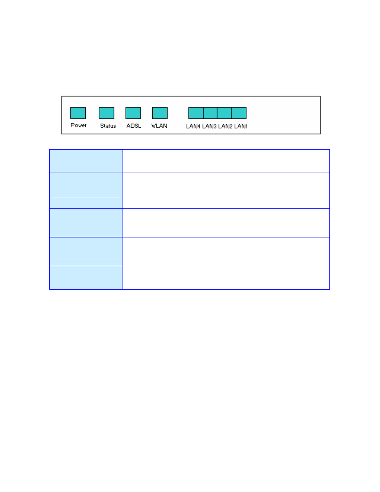
Front Panel Display
Place the Router in a location that permits an easy view of the LED indicators on the front panel.
The LED indicators on the front panel include Power, Status, ADSL, WLAN, and LAN. The ADSL, WLAN, and
LAN indicators monitor link status and activity (Link/Act).
Power
Steady green light indicates the unit is powered on. When the device is
powered off this remains dark.
Status
Lights steady green during power on self-test (POST). Once the connection
status has been settled, the light will blink green. If the indicator lights
steady green after the POST, the system has failed and the device should be
rebooted.
ADSL (Link/Act)
Steady green light indicates a valid ADSL connection. This will light after the
ADSL negotiation process has been settled. A blinking green light indicates
activity on the WAN (ADSL) interface.
WLAN (Link/Act)
Steady green light indicates a wireless connection. A blinking green light
indicates activity on the WLAN interface
LAN (Link/Act)
A solid green light indicates a valid link on startup. These lights blink when
there is activity currently passing through the Ethernet port.
4
Page 15
WBMR-G54 Wireless ADSL Router User Guide
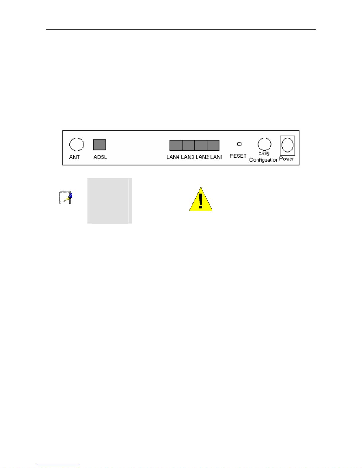
Rear Panel Connections
All cable connections to the Router are made at the rear panel. Connect the power adapter here to power on the Router.
Use the Reset button to restore the settings to the factory default values in the next chapter for instructions on using the
reset button).
Connect network cables:
1. Insert the ADSL (telephone) cable included with the Router into the ADSL port and then connect the cable to
your telephone line.
2. Insert one end of the Ethernet cable into one of the LAN ports on the back panel of the Router and the other
end of the cable to an Ethernet Adapter or available Ethernet port on your computer.
Note
To manually
reboot the
Router,
disconnect and
then reconnect
the power.
WARNING!
Using a power supply with a
different voltage rating will
damage the device and void
the warranty of this product.
Setting Up a Wireless Network
In order to get the best performance from the wireless component of the Router, you should have some basic
understanding of how wireless networks operate. Wireless networking is a relatively new technology and there are more
factors to consider when setting up or designing a wireless network than designing a wired network. If you are setting
up a wireless network, especially if you are using multiple access points and/or covering a large area, good planning
from the outset can ensure the best possible reliability, performance, coverage and effective security.
Radio
Wireless local network (as called WI-FI) devices such as notebook computers and wireless access points use
electromagnetic waves within a broad, unlicensed range of the radio spectrum (between 2.4GHz and 2.5GHz) to
transmit and receive radio signals. A wireless access point (AP) becomes a base station for the wireless nodes (notebook
computer for example) in its broadcast range. Often a wireless access point such as the AP embedded in the WBMRG54, will also provide a connection to a wired network - usually Ethernet - and ultimately an Internet co nnection. The
IEEE 802.11 standard precisely defines the encoding techniques used to digitally used for data transmission. The
WBMR-G54 can be used by IEEE 802.11g and 802.11b devices. These two standards are compatible but use different
algorithms for data transmission.
802.11g uses a method called Orthogonal Frequency Division Multiplexing (OFDM) for transmitting data at higher data
rates. OFDM is a more efficient encoding method than Direct Sequence Spread Spectrum (DSSS) transmission, the
method used by 802.11b devices. However, in order to support different data transmission rates while also be
compatible with 802.11b, 802.11g uses a combination of OFDM and DSSS when 802.11b devices are present.
Range
An access point will send and receive signals within a limited range. Also, be aware that the radio signals are emitted in
all directions giving the access point a spherical operating range. The physical environment in which the AP is
5
Page 16

WBMR-G54 Wireless ADSL Router User Guide
operating can have a huge impact on its effectiveness. If you experience low signal strength or slow throughput,
consider positioning the Router in a different location. See the discussion below concerning the wireless environment
and location of the AP (WBMR-G54).
SSID and Channel
Wireless networks use an SSID (Service Set Identifier) as means of identifying a group of wireless devices, similar to a
domain or subnet. This allows wireless devices to roam from one AP to another and remain connected. Wireless devices
that wish to communicate with each other must use the same SSID. Several access points can be set up using the same
SSID so that wireless stations can move from one location to another without losing connection to the wireless network.
The embedded wireless access point of the Router operates in Infrastructure mode. It controls network access on the
wireless interface in its broadcast area. It will allow access to the wireless network to devices using the correct SSID
after a negotiation process takes place. By default, the WBMR-G54 broadcasts its SSID so that any wireless station in
range can learn the SSID and ask permission to associate with it. Many wireless adapters are able to survey or scan the
wireless environment for access points. An access point in Infrastructure mode allows wireless devices to survey that
network and select an access point with which to associate. You may disable SSID broadcasting in the web manager’s
wireless menu.
In addition, the AP can use different channels (frequency bands) to avoid unwanted overlap or interfere between contro l
zones of separate APs. Wireless nodes must use the same SSID and the same channel as the AP with which it wishes to
associate. However, because of the nature of the CSMA/CA (carrier sense multiple access with collision avoidance)
protocol, using the same channel on two different APs can contribute significantly to wireless congestion. If you are
using multiple APs on your network and are experiencing low throughput or sign ificant transmission delay, carefully
consider how channels are assigned to the different APs.
Wireless Security
Various security options are available on the WBMR-G54 including open or WEP and WPA (including WPA-PSK).
Authentication may use an open system or a shared key. Read below for more information on configuring security for
the wireless interface.
Location and Wireless Operation
Many physical environmental factors can impact wireless networks. Radio waves are used to carry the encoded data
between devices. These radio transmissions can become degraded due to signal attenuation, multi-path disto rtion and
interference or noise. Attenuation simply means that the strength of the signal weakens with the distance it travels, even
if the transmission path is unobstructed. Multi-path distortion occurs when radio signals bounce off objects like walls,
ceilings, metal appliances, etc. This may cause a signal to be duplicated, with each separate yet identical signal arriving
at a receiver at different times. Interference and noise from electrical devices such as microwave ovens, fluorescent
lights, automobile engines and other radio emitting devices can cause signal degradation. With all this in mind, choose a
location for all your access points including the WBMR-G54.
The access point can be placed on a shelf or desktop, ideally you should be able to see the LED indicators on the front if
you need to view them for troubleshooting.
Wireless networking lets you access your network from nearly anywhere you want. However, the number of walls,
ceilings, or other objects that the wireless signals must pass through can limit signal range. Typical ranges vary
depending on the types of materials and background RF noise in your home or business. To range and signal strength,
use these basic guidelines:
1. Keep the number of walls and ceilings to a minimum: The signal emitted from Wireless LAN devices can
penetrate through ceilings and walls. However, each wall or ceiling can reduce the range of Wireless LAN
devices from 1 to 30M. Position your wireless devices so that the number of walls or ceilings obstructing the
signal path is minimized.
2. Consider the direct line between access points and workstations: A wall that is 0.5 meters thick, at a 45-
degree angle appears to be almost 1 meter thick. At a 2-degree angle, it is over 14 meters thick. Be careful to
position access points and client adapters so the signal can travel straight through (90º angle) a wall or ceiling
for better reception.
6
Page 17

WBMR-G54 Wireless ADSL Router User Guide
3. Building Materials make a difference: Buildings constructed using metal framing or doors can reduce
effective range of the device. If possible, position wireless devices so that their signal can pass through drywall
or open doorways, avoid positioning them so that their signal must pass through metallic materials. Poured
concrete walls are reinforced with steel while cinderblock walls generally have little or no structural steel.
4. Position the antennas for best reception: Play around with the antenna position to see if signal strength
improves. Some adapters or access points allow the user to judge the strength of the signal.
5. Keep your product away (at leas t 1- 2 met ers) from electrical devices: Position wireless devices away from
electrical devices that generate RF noise such as microwave ovens, monitors, electric motors, etc.
7
Page 18

WBMR-G54 Wireless ADSL Router User Guide
2
Hardware Installation
The WBMR-G54 Wireless ADSL Router maintains three separate interfaces, an Ethernet LAN, a wireless LAN and an
ADSL Internet (WAN) connection. Carefully consider the Router’ s location suitable for connectivity for your Ethernet
and wireless devices. You must have a functioning broadband connection via a bridge device such as a Cable or ADSL
modem in order to use the Router’s WAN function.
Place the Router in a location where it can be connected to the various devices as well as to a power source. The Router
should not be located where it will be exposed to moisture, direct sunlight or excessive heat. Make sure the cables and
power cord are placed safely out of the way so they do not create a tripping hazard. As with any electrical appliance,
observe common sense safety procedures.
The Router can be placed on a shelf, desktop, or other stable platform. If possible, you should be able to see the LED
indicators on the front if you need to view them for troubleshooting.
Power on Router
CAUTION: The Router must be used with the power adapter included with the device.
To power on the Router:
1. Insert the AC Power Adapter cord into the power receptacle located on the rear panel of the Router and plug
the adapter into a suitable nearby power source.
2. You should see the Power LED indicator light up and remain lit. The Status LED should light solid green and
begin to blink after a few seconds.
3. If the Ethernet port is connected to a working device, check the Ethernet Link/Act LED indicators to make sure
the connection is valid. The Router will attempt to establish the ADSL connection, if the ADSL line is
connected and the Router is properly configured this should light up after several seconds. If this is the first
time installing the device, some settings may need to be changed before the Router can establish a connection.
Factory Reset Button
The Router may be reset to the original factory default settings by depressing the reset button for a few seconds while
the device is powered on. Use a ballpoint or paperclip to gently push down the reset button. Remember that this will
wipe out any settings stored in flash memory including user account information and LAN IP settings. The device
settings will be restored to the factory default IP address 192.168.11.1 and the subnet mask is 255.255.255.0, the default
management Username is “admin” and the default Password is “admin.”
8
Page 19
WBMR-G54 Wireless ADSL Router User Guide
Network Connections
Wired network connections are provided through the ADSL port and the four Ethernet ports on the back of the Router.
See the Rear Panel diagram above and the illustrations below for examples.
Connect ADSL Line
Use the ADSL cable included with the Router to connect it to a telephone wall socket or receptacle. Plug one end of the
cable into the ADSL port (RJ-11 receptacle) on the rear panel of the Router and insert the other end into the RJ-11 wall
socket. If you are using a low pass filter device, follow the instructions included with the device or given to you by your
service provider. The ADSL connection represents the WAN interface, the connection to the Internet. It is the physical
link to the service provider’s network backbone and ultimately to the Internet.
Connect Router to Ethernet
The Router may be connected to a single computer or Ethernet device through the 10BASE-TX Ethernet port on the
rear panel. Any connection to an Ethernet concentrating device such as a switch or hub must operate at a speed of
10/100 Mbps only. When connecting the Router to any Ethernet device that is capable of operating at speeds higher
than 10Mbps, be sure that the device has auto-nego tiation (NWay) enabled for the connecting port.
Use standard twisted-pair cable with RJ-45 connectors. The RJ-45 port on the Router is a crossed port (MDI-X). Follow
standard Ethernet guidelines when deciding what type of cable to use to make this connection. When connecting the
Router directly to a PC or server use a normal straight-through cable. You should use a crossed cable when connecting
the Router to a normal (MDI-X) port on a switch or hub. Use a normal straight -through cable when connecting it to an
uplink (MDI-II) port on a hub or switch.
The rules governing Ethernet cable lengths apply to the LAN to Router connection. Be sure that the cable con necting
the LAN to the Router does not exceed 100 meters.
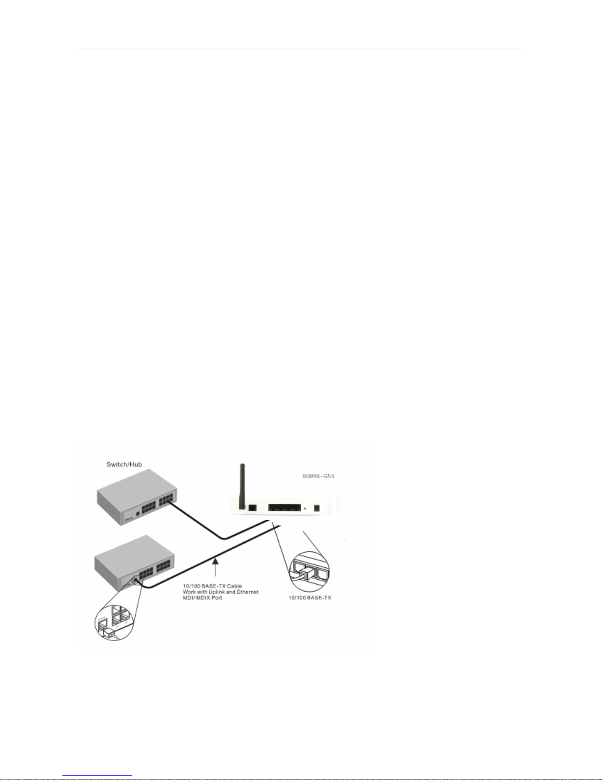
Hub or Switch to Router Connection
Connect the Router to an uplink port (MDI-II) on an Ethernet hub or switch with a straight-through cable as shown in
the diagram below:
If you wish to reserve the uplink
port on the switch or hub for
another device, connect to any on
the other MDI-X ports (1x, 2x, etc.)
with a crossed cable.
9
Page 20

WBMR-G54 Wireless ADSL Router User Guide
Computer to Router Connection
You can connect the Router
directly to a 10/100BASE-TX
Ethernet adapter card (NIC)
installed on a PC using the Ethernet
cable provided as shown in this
diagram.
10
Page 21

WBMR-G54 Wireless ADSL Router User Guide
3
Basic Router Configuration
The first time you set up the Router it is recommended that you configure the WAN conn ection using a single co mputer
making sure that both the computer and the Router are not connected to the LAN. Once the WAN connection is
functioning properly, you may continue to make changes to Router configuration including IP settings and DHCP setup.
This chapter is concerned with using your computer to configure the WAN connection. The following chapter describes
the various windows used to configure and monitor the Router including how to change IP settings and DHCP server
setup.
Configuration Summary
1. Connect to the Router To configure the WAN connection used by the Router it is first necessary to
communicate with the Router through its management interface, which is HTML-based and can be accessed
using a web browser. To access the management software your computer must be able to “see” the Router.
Your computer can see the Router if it is in the same “neighborhood” or subnet as the Router. This is
accomplished by making sure your computer has IP settings that place it in the same subnet as the Router. The
easiest way to make sure your computer has the correct IP settings is to configure it to use the DHCP server in
the Router. The next section describes how to change the IP configuration for a computer running a Windows
operating system to be a DHCP client.
2. Configure the WAN Connection Once your are able to access the configuration software you can proceed to
change the settings required to establish the ADSL connection and connect to the service provider’s network.
There are different methods used to establish the connection to the service provider’s network and ultimately to
the Internet. You should know what Encapsulation and connection type you are required to use for your ADSL
service. It is also possible that you must change the PVC settings used for the ADSL connection. Your service
provider should provide all the information you need to configure the WAN connection.
Configuring IP Settings on Your Computer
In order to configure your system to receive IP settings from the Router your computer must first have the TCP/IP
protocol installed. If you have an Ethernet port on your computer, it probably already has TCP/IP protocol installed. If
you are using Windows XP the TCP/IP is enabled by default for standard installatio n s. Instructio ns fo r configu ring your
computer to receive IP settings from the Router are provided in Appendix B on page 103.
For computers running non-Windows operating systems, follow the instructions for your OS that configure the system
to receive an IP address from the Router, that is, configure the system to be a DHCP client.
Note
If you are not sure how to configure your Windows computer to be a DHCP client, see
Configuring IP Settings on Your Computer beginning on page 103.
11
Page 22
WBMR-G54 Wireless ADSL Router User Guide
Access the Configuration Manager
In order to make sure your computer’s IP settings allow it to communicate with the Router, it is advisable to configure
your system be a DHCP client – that is, it will get IP settings from the Router. Appendix B describes how to configure
different Windows operating systems to “Obtain IP settings automatically”.
Note
Be sure that the web browser on your computer is not configured to use a proxy server in the
Internet settings. In Windows Internet Explorer, you can check if a proxy server is enabled using the
following procedure:
1. In Windows, click on the Start button and choose Control Panel.
2. In the Control Panel window, click on the Network and Internet Options icon.
3. In the Network and Internet Connections window, click the Internet Options icon.
4. In the Internet Properties window, click on the Connections tab and click on the LAN Settings
button
5. Verify that the “Use a proxy server for your LAN (These settings will not apply to dial-up or VPN
connections).” option is NOT checked. If it is checked, click in the checked box to deselect the
option and click OK.
Alternatively, you can access this Internet Options menu using the Tools pull-down menu in
Internet Explorer.
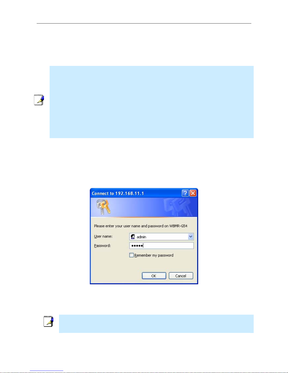
Login to Home Page
To use the web-based management software, launch a suitable web browser and direct it to the IP address of the Router.
Type in http:// followed by the default IP address, 192.168.11.1 in the ad dress bar of the browser. The U RL in the
address bar should read: http://192.168.1.1.
A dialog box prompts for the User Name and Password. Type in the default User Name “admin,” and the default
Password “admin” then click the OK button to access the web-based manager.
Enter Password
You should change the web-based manager access user name and password once you have verified that a connection
can be established. The user name and password allows any PC within the same subnet as the Router to access the webbased manger.
Note
The user name and password used to access the web-based manager is NOT the same as the
ADSL account user name and password needed for PPPoE/PPPoA connections to access the
Internet.
12
Page 23
WBMR-G54 Wireless ADSL Router User Guide
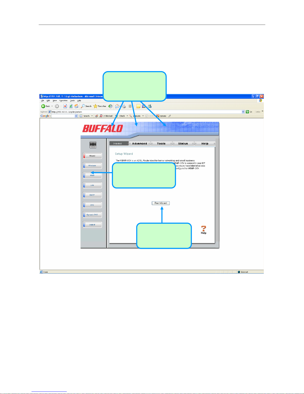
Configure the Router
When you successfully connect to the web manager, the Home directory tab will display the Setup Wizard window.
You can launch the Setup Wizard from this page or use the buttons located in the left panel of the web page to view
other windows used for basic configuration.
Click the Run Wizard
button to launch the
Setup Wizard
Click on a directory tab to
the windows availa
in that directory
view ble
C lick on a button to use or
view the window
Web Manager – First Time Log On
All configuration and management of the Router is done using the web-based management interface pictured in the
above example. The configuration windows are accessed by clicking on the directory tabs: Home, Advanced, Tools,
Status, and Help. Each tab has associated window buttons in the left hand panel of the web interface. Basic setup of the
Router can be completed in the windows accessed from the Home directory including: (Setup) Wizard, Wireless,
WAN (Internet), LAN (to configure the IP address of the Router) DHCP, DNS and Dynamic DNS.
13
Page 24
WBMR-G54 Wireless ADSL Router User Guide
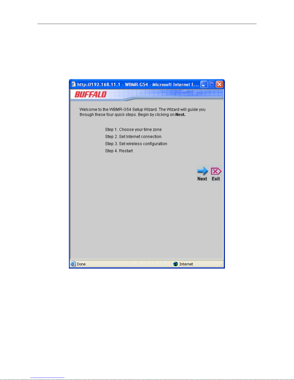
Wizard
To use the Setup Wizard, click the Run Wizard button in the first browser window and follow the instructions in the
pop-up window that appears.
The initial window summarizes the setup process. Click the Next button to proceed. You may stop using the Setup
Wizard at any time by clicking the Exit button. If you exit the wizard you will return to the Setup Wizard window
without saving any of the settings changed during the process.
The first pop-up window of the Setup Wizard lists the basic steps in the process. These steps are as follows:
1. Set the system time.
2. Configure the connection to the Internet.
3. Set the wireless configuration.
4. Save the new configuration settings and reboot the system.
14
Page 25
WBMR-G54 Wireless ADSL Router User Guide
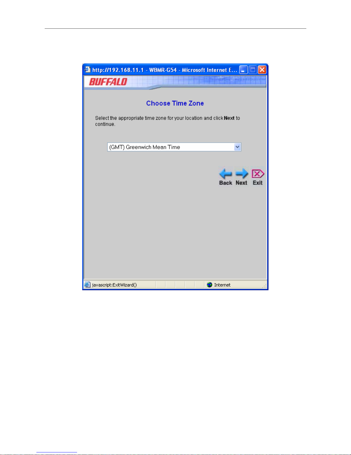
Using the Setup Wizard - Choose Time Zone
Choose the time zone you are in from the pull-down menu and click Next. This sets the system time used for the
Router. If you wish to return to the previous window during the setup process, click the Back button.
15
Page 26
WBMR-G54 Wireless ADSL Router User Guide
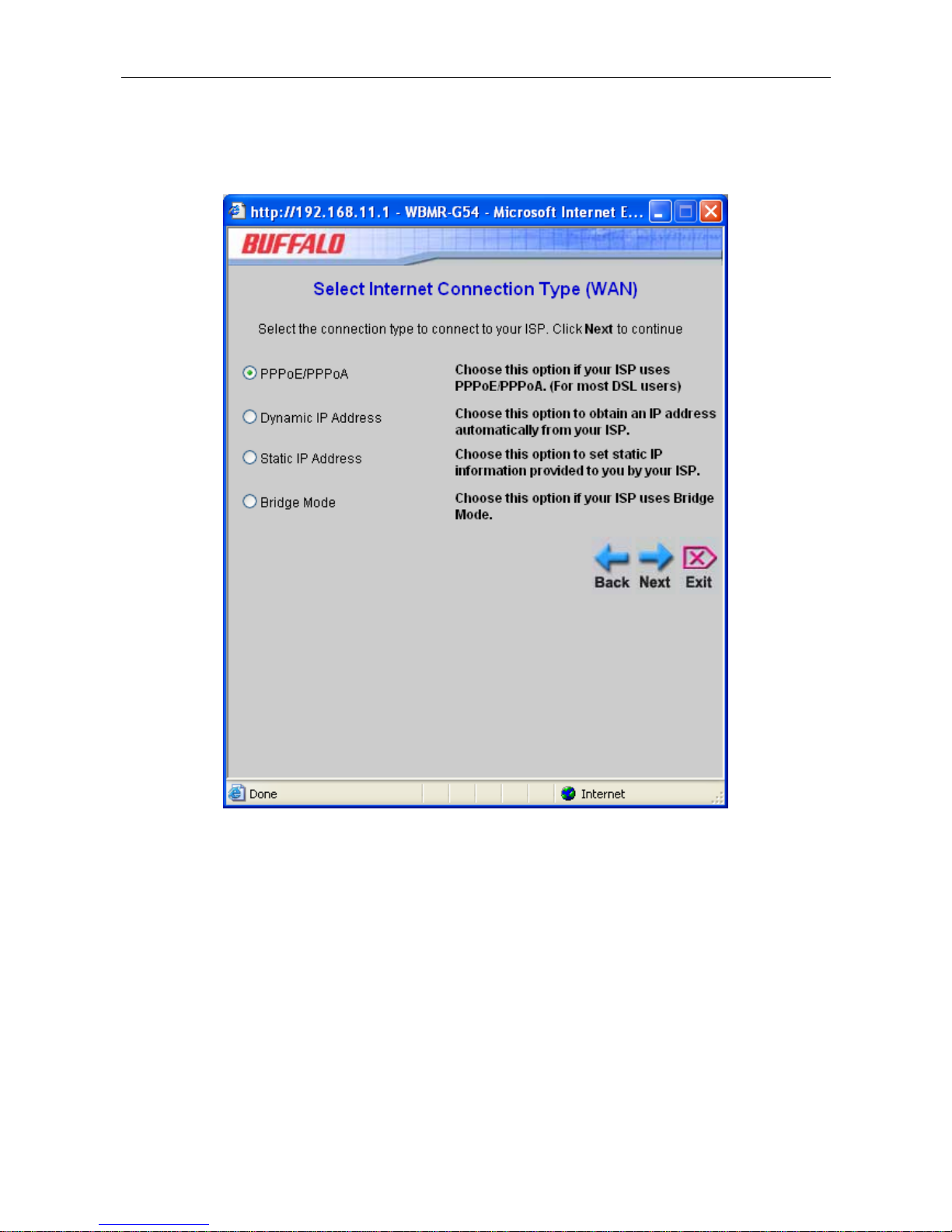
Using the Setup Wizard - Choose Connection Type
Now select the Connection Type used for the Internet connection. Your ISP has given this information to you. The
connection types available for “Multi-User” Mode are PPPoE/PPPoA, Dynamic IP Address, Static IP Address, and
Bridge Mode. Each connection type has different settings that are configured in the next Setup Wizard window.
Select the Connection Type specific to your service and click Next to go to the next Setup Wizard window. Follow
the instructions below for the type of connection you have selected.
16
Page 27
WBMR-G54 Wireless ADSL Router User Guide
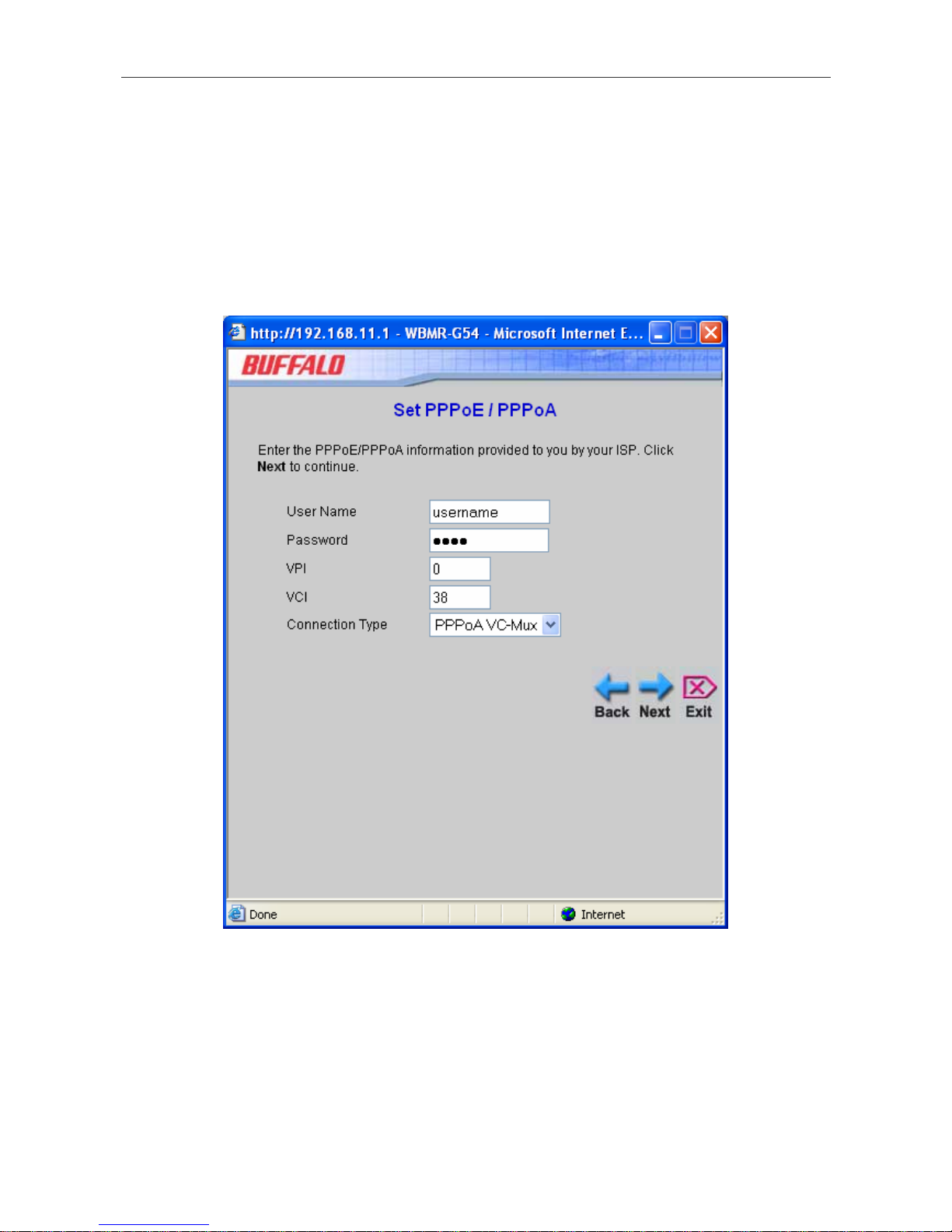
Using the Setup Wizard - For PPPoE/PPPoA connections:
1. Type in the Username and Password used to identify and verify your account to the ISP.
2. Select the specific Connection Type from the drop-down menu. The available PPP connection and
encapsulation types are PPPoE LLC, PPPoA LLC and PPPoA VC-Mux.
3. If you are instructed to change the VPI or VCI number, type in the correct setting in the available entry fields.
Most users will not need to change these settings. The Internet connection cannot function if these values are
incorrect.
4. Click Next to go to the Set Wireless LAN Connection pop-up window.
17
Page 28
WBMR-G54 Wireless ADSL Router User Guide
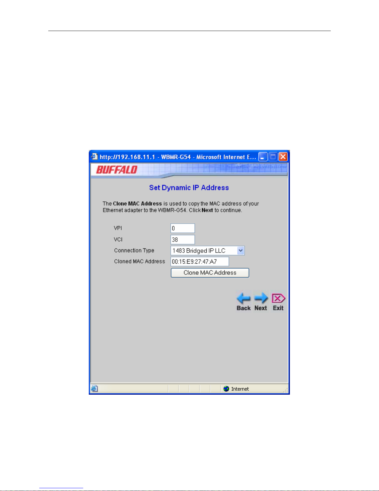
Using the Setup Wizard - For Dynamic IP Address connections:
1. Select the specific Connection Type from the drop-down menu. The available Dynamic IP Address
connection and encapsulation types are 1483 Bridged IP LLC and 1483 Bridged IP VC-Mux.
2. If you are instructed to change the VPI or VCI number, type in the correct setting in the available entry fields.
Most users will not need to change these settings. The Internet connection cannot function if these values are
incorrect.
3. You may want to copy the MAC address of your Ethern et adapter to the Router. Some ISPs record the unique
MAC address of your computer’s Ethernet adapter when you first access their network. This can prevent the
Router (which has a different MAC address) from being allowed access to the ISPs network (and the Internet).
To clone the MAC address of your computer’s Ethernet adapter, type in the MAC address in the Cloned MAC
Address field and click the Clone MAC Address button. This will cop y the information to a file used by the
Router to present to the ISP’s server used for DHCP.
4. Click Next to go to the Set Wireless LAN Connection pop-up window.
18
Page 29
WBMR-G54 Wireless ADSL Router User Guide
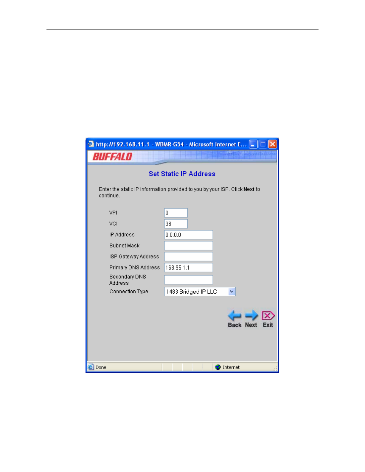
Using the Setup Wizard - For Static IP Address connections:
1. Select the specific Connection Type from the drop-down menu. The available Static IP Address connection
and encapsulation types are 1483 Bridged IP LLC, 1483 Bridged IP VC-Mux, 1483 Routed IP LLC, 1483
Routed IP VC-Mux and IPoA.
2. Change the IP Address, Subnet Mask, ISP Gateway Address, Primary DNS Address, and Secondary DNS
Server IP Address as instructed by your ISP. For IPoA connections it may also be necessary to change the
ARP Server Address. IPoA connection users who have not been given this information should leave the field
blank.
3. If you are instructed to change the VPI or VCI number, type in the correct setting in the available entry fields.
Most users will not need to change these settings. The Internet connection cannot function if these values are
incorrect.
4. Click Next to go to the Set Wireless LAN Connection pop-up window.
19
Page 30
WBMR-G54 Wireless ADSL Router User Guide
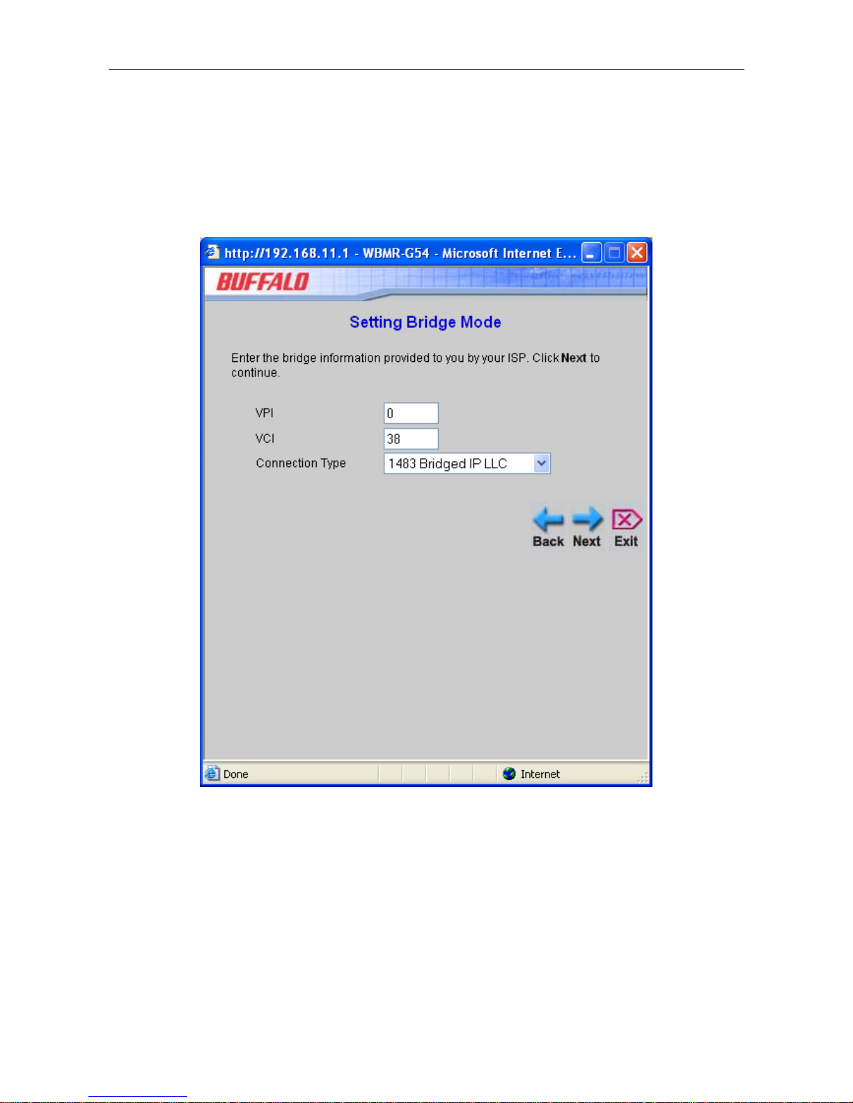
Using the Setup Wizard - For Bridge Mode connections:
1. Select the specific Connection Type from the drop-down menu. The available Bridge Mode connection and
encapsulation types are 1483 Bridged IP LLC and 1483 Bridged IP VC-Mux.
2. If you are instructed to change the VPI or VCI number, type in the correct setting in the available entry fields.
Most users will not need to change these settings. The Internet connection cannot function if these values are
incorrect.
3. Click Next to go to the Set Wireless LAN Connection window.
20
Page 31

WBMR-G54 Wireless ADSL Router User Guide
Using the Setup Wizard - For Wireless LAN connections:
1. Click the Enable AP box to allow the router to operate in the wireless environment.
2. The SSID identifies members of the Service Set. Accept the default name or change it to something else. If
the default SSID is changed, all other devices on the wireless network must use the same SSID.
3. The wireless Channel number is available from your Internet Service Provider (ISP). What channels are
available for use by the access point depends on the local regulatory environment. Remember that all devices
communicating with the device must use the same channel (and use the same SSID). Use the drop-down
menu to select the channel used for your 802.11g wireless LAN.
4. The default Security setting is AirStation OneTouch Secure System (AOSS). AOSS automatically detects
and configures other AOSS enabled wireless devices and clients and seamlessly negotiates the most secure
connection possible between your wireless devices. The other two Security options are WEP and WPA.
5. Click Next to go to the next window and complete the Setup Wizard.
21
Page 32

WBMR-G54 Wireless ADSL Router User Guide
Using the Setup Wizard - Finish and Restart
Finally you can confirm that the setup process is completed. If you are satisfied that you have entered all the necessary
information correctly, click the Restart button to save the new configuration settings and restart the Router. If you need
to change settings from a previous window, click the Back button.
Do not turn the Router off while it is restarting. After the Router is finished restarting, you are now ready to continue
to configure the Router as desired. You may want to test the WAN connection by accessing the Internet with your
browser.
22
Page 33

WBMR-G54 Wireless ADSL Router User Guide
Wireless
To configure the Router’s basic configuration settings without running th e Setup Wizard, you can access the windows
used to configure Wireless, WAN, LAN, DHCP, DNS, and Dynamic DNS settings directly from the Home directory.
To access the Wireless Settings window, click on the Wireless link button on the left side of the first window that
appears when you successfully access the web manager.
Wireless Settings window
Click the Enable AP box to allow the router to operate in the wireless environment.
The SSID identifies members of the Service Set. Accept the default name or change it to something else. If the default
SSID is changed, all other devices on the wireless network must use the same SSID.
What channels are available for use by the access point depends on the local regulatory environment. Remember that all
devices communicating with the device must use the same channel (and use the same SSID). Use the drop-down menu
to select the Channel used for your 802.11g wireless LAN. The wireless channel number is available from your
Internet Service Provider (ISP).
The default for Security is AOSS. AirStation OneTouch Secure System automatically detects and configures other
AOSS enabled wireless devices and clients and then negotiates the most secure connection possible between your
wireless devices. The other two Security options are WEP and WPA.
Click Apply when you are finished making your changes on this window.
23
Page 34

WBMR-G54 Wireless ADSL Router User Guide
Wireless Security
The WBMR-G54 offers two main types of network security: WEP and WPA.
WEP
WEP (Wireless Encryption Protocol) encryption can be enabled for security and privacy. WEP encrypts the data
portion of each frame transmitted from the wireless adapter using one of the predefined keys. The router offers 64-,
128-, or 256-bit encryption with four keys available.
To bring up the Wireless Settings window for WEP, click the WEP radio button.
Wireless Settings window – WEP
1. Make sure the Enable AP checkbox at the top of the window has been ticked.
2. From the drop-down menu, select an Authentication Type: Open, Shared, or Both.
24
Page 35

WBMR-G54 Wireless ADSL Router User Guide
3. Select a key by clicking a radio button on the left, select an encryption level from the drop-down menu on the
right, and then enter the proper-length key. (Key length is outlined at the bottom of the window.)
4. Click Apply.
WPA (Wi-Fi Protected Access)
Wi-Fi Protected Access was designed to provide improved data encryption, perceived as weak in WEP, and to provide
user authentication, largely nonexistent in WEP.
For most small networks, such as in a small business or home-based enterprise, WPA is the easiest way to obtain
effective network security.
Wireless Settings window – WPA
Enter the appropriate parameters for the type of key selected from this window:
• Group Key Interval: The time (in seconds) after which the Group Key is changed automatically (1-99999).
• PSK String String: This Pre-Shared Key is an alphanumeric value of 1-63 characters in length
When you are finished, click Apply.
Notice If encryption of any kind, at any level is applied to the Router, all de vices on the
network must comply with all security measures.
25
Page 36

WBMR-G54 Wireless ADSL Router User Guide
WAN
To access the WAN Settings window, click on the WAN link button on the left side of the first window that appears
when you successfully access the web manager.
PPPoE/PPPoA
Follow the instructions below to configure the Router to use a PPPoE or PPPoA for the Internet connection. Make sure
you have all the necessary information before you configure the WAN connection.
26
Page 37

WBMR-G54 Wireless ADSL Router User Guide
WAN Settings window – PPPoE/PPPoA
27
Page 38

WBMR-G54 Wireless ADSL Router User Guide
To set up a PPPoE or PPPoA connection:
1. If not already selected, choose the PPPoE/PPPoA option from the WAN Settings pull-down menu.
PPPoE/PPPoA is selected by default if you are configuring the Router for the first time.
2. Under the ATM VC Settings at the top of the window should not be changed unless you have been instructed to
change them. However, if you are instructed to change the VPI or VCI values, type in the values assigned for your
account. Leave the PVC and Virtual Circuit setting at the default (Pcv0 and Enabled) values for now. This can be
used later if you are configuring multiple virtual circuits for your ADSL service. For more information on ATM
VC Settings, see the table on page 41 below.
3. Under the PPPoE/PPPoA heading, type the User Name and Password used for your ADSL account. A typical
User Name will be in the form
user1234@isp.co.uk. The Password may be assigned to you by your ISP or you
may have selected it when you set up the account with your ISP.
4. Choose the Connection Type from the pull-down menu located under the User Name and Password entry fields.
This defines both the connection protocol and en capsulation method used for your ADSL service. The available
options are PPPoE LLC, PPPoA LLC, and PPPoA VC-Mux, and. If have not been provided specific information
for the Connection Type setting, leave the default setting.
5. Leave the MTU value at the default setting (default = 1400) unless you have specific reasons to change this (see
table below).
6. Leave the MRU value at the default setting (default = 1492) unless you have specific reasons to change this (see
table below).
7. Leave the Default Route enabled if you want to use the Router as the default route to the Internet for your LAN .
Whenever a computer on the LAN attempts to access the Internet, the Router becomes the Internet gateway to the
computer. If you have an alternative route for Internet traffic you may disable this without effecting the Router’s
connection.
8. NAT should remain Enabled. If you disable NAT, you will not be able to use more than one computer for Internet
connections. NAT is enabled and disabled system-wide, therefore if you ar e using multiple virtual connections,
NAT will disabled on all connections.
9. The Firewall should remain enabled for most users. If you choose to disable this you will not be able to use the
features configured in the Firewall Configura tion and Filters windows located in the Advanced directory. See
the next chapter for more details on these windows.
10. Typically the globally IP settings (i.e. IP address for the WAN interface) for a PPPoA or PPPoA connection will
use Dynamic IP assignment from the ISP. Some accounts may be assigned a specific global IP address. If you
have been give an IP address for you PPPoE/PPPoA connection, select the Static IP option from the IP Control
pull-down menu. This menu can be used to configure the WAN port as an Unnumbered IP interface. (See table
below for Unnumbered IP).
11. Choose the desired Connection Setting. Select from: Always ON, Connection On Demand, or Manual. Most
users will want to choose the default connection setting, Always ON.
12. Most users will not need to change ATM settings. If this is the first time you are setting up the ADSL connection
it is recommended that you leave the Service Category settings at the default values until yo u have established the
connection. See the table on page 40 for a description of the parameters available for ATM traffic shaping.
13.
When you are satisfied that all the WAN settings are configured correctly, click on the Apply button.
14. The new settings must be saved and the Router must be restarted for the settings to go into effect. To save and
reboot the Router, click on the Tools directory tab and then click the System button. In the System Settings
window, click the Save and Reboot button under Save Settings and Reboot the System.
15. Click OK when the following “Save and restart?” dialog box opens.
28
Page 39

WBMR-G54 Wireless ADSL Router User Guide
16. The Router will save the new settings and restart. Upon restarting the Router will automatically establish the WAN
connection.
Setting details for PPPoE/PPPoA connections:
PPPoE/PPPoA Parameters Description
User Name For PPP connections, a User Name and Password are used to identify
and verify your account to the ISP. Enter the User Name for your ADSL
service account. User names and passwords are case-sensitive, so enter
this information exactly as given to you by your ISP.
Password Together with the User Name, this is used to verify your account to the
ISP. Enter the Password exactly as given to you by your ISP.
Connection Type This specifies the protocol (PPPoE or PPPoA) and the encapsulation
method (LLC or VC-Mux) used for your connection. The options available
are
PPPoE LLC, PPPoA LLC
or
PPPoA VC-Mux
.
MTU The Maximum Transmission Unit size may be changed if you want to
optimize efficiency for uploading data through the WAN interface. The
default setting (
1400
bytes) should be suitable for most users. Some
user may want to adjust the setting to optimize performance for wireless
traffic or when low latency is desired (such as with Internet gaming). It
is highly recommended that the user research how adjusting the MTU
may effect network traffic for better or worse.
MRU Similar to the MTU, except this applies to Maximum Received Unit size
for downloading data. Most users will be happy with the default setting
(
1492
bytes). However this may also be optimized for fast downloads of
general bulk Internet traffic, for low latency or for downloading to
computers on the Wireless LAN. As with the MTU setting, the user
should carefully consider how changing the MRU may affect Internet
downloads for all systems on your LAN.
Default Route When this is enabled, the Router will be considered to be the primary
gateway to the Internet and WAN for systems on your network. If you
are using the Router on a network with one or more alternative gateway
routers, you may prefer to disable this if you will use another router as
the primary gateway.
NAT Network Address Translation may be enabled or disabled with the pull-
down menu. Keep in mind that disabling NAT allows only a single
computer to be used for Internet access through the Router. NAT is
enabled and disabled for the Router on all connections (i.e. Pvc0 – Pvc7)
if your Router is set up for multiple virtual connections.
Firewall Use this to universally enable or disable the Firewall and Filter features
available in the Router. If you disable this you will not be able to
configure settings in the Firewall Configuration window or Filters
window in the Advanced directory.
IP Control This is used to determine how global IP settings are handled for the
WAN interface. Typically PPPoE or PPPoA connections will use the
29
Page 40

WBMR-G54 Wireless ADSL Router User Guide
default setting for
Dynamic IP
. Some users will be given a specific IP
address for the WAN interface. In this case you need to change this
setting to
Static IP
. When Static IP is selected in the IP Control menu,
you need to type in the global IP address provided to you by your ISP.
The
IP Unnumbered
option is used if you want to set up a non-TCP/IP
port protocol link through the WAN interface. An IP Unnumbered
interface does not have an IP address and therefore cannot be managed
via Telnet or any other TCP/IP application.
Static IP If you have selected the
Static IP
option in the IP Control menu, type in
the global IP address used for your WAN interface. Your ISP should
provide this IP address to you.
Connection Setting Select the desired option: Always ON, Connection On Demand, or
Manual. Most users will want to choose the default connection setting,
Always ON.
30
Page 41

WBMR-G54 Wireless ADSL Router User Guide
Bridge Mode
WAN Settings window – Bridge Mode
Select the connection type used for your account. The window will display settings that are appropriate for the
connection type you select. Follow the instruction below according to the type of connectio n you select in the WAN
Settings window.
For Bridged connections it will be necessary for most users to install additional software on any computer that will the
Router for Internet access. The additional software is used for the purpose of identifying and verifying your account,
and then granting Internet access to the computer requesting the connection. The connection software requires the user
to enter the User Name and Password for the ISP account. This information is stored on the computer, not in the Router.
Follow the instructions below to configure a Bridged connection for the WAN interface.
1. Choose the Bridge Mode option from the WAN Settings pull-down menu.
31
Page 42

WBMR-G54 Wireless ADSL Router User Guide
2. Under the ATM VC Settings at the top of the window should not be changed unless you have been instructed
to change them. However, if you are instructed to change the VPI or VCI values, type in the values assigned
for your account. Leave the PVC and Virtual Circuit setting at the default (Pcv0 and Enabled) values for
now. This can be used later if you are configuring multiple virtual circuits for your ADSL service. For more
information on ATM VC Settings, see the table on page 41 below.
3. Under the Bridge Mode heading, choose the Connection Type from the pull-down menu. This defines both
the connection type and encapsulation method used for your ADSL service. The available options are 1483
Bridged IP LLC and 1483 Bridged IP VC-Mux. If have not been provided specific information for the
Connection Type setting, leave the default setting.
4. Most users will not need to change ATM settings. If this is the first time you are setting up the ADSL
connection it is recommended that you leave the Servic e Category settings at the default values until you hav e
established the connection. See the table on page 40 for a description of the parameters available for ATM
traffic shaping.
5. When you are satisfied that all the WAN settings are configured correctly, click on the Apply button.
6. The new settings must be saved and the Router must be restarted for the settings to go into effect. To save and
reboot the Router, click on the Tools directory tab and then click the System button. In the System Settings
window, click the Save and Reboot button under Save Settings and Reboot the System.
7. Click OK when the following “Save and restart?” dialog box opens.
8. The Router will save the new settings and restart. Upon restarting the Router will automatically establish the
WAN connection.
32
Page 43

WBMR-G54 Wireless ADSL Router User Guide
Dynamic IPAddress
A Dynamic IP Address connection configures the Router to automatically obtain its global IP address from a DHCP
server on the ISP’s network. The service provider assigns a global IP address from a pool of addresses available to the
service provider. Typically the IP address assigned has a long lease time, so it will likely be the same address each time
the Router requests an IP address.
To configure a Dynamic IP Address connection, perform the steps listed below. Some of the settings do not need to be
changed the first time the device is set up, but can be changed later if you choose.
WAN Settings window – Dynamic IP Address
33
Page 44

WBMR-G54 Wireless ADSL Router User Guide
To configure a Dynamic IP Address connection for the WAN, follow these steps:
1. Choose the Dynamic IP Address option from the WAN Settings pull-down menu.
2. Under the ATM VC Settings at the top of the window should not be changed unless you have been instructed to
change them. However, if you are instructed to change the VPI or VCI values, type in the values assigned for
your account. Leave the PVC and Virtual Circuit setting at the default (Pcv0 and Enabled) values for now. This
can be used later if you are configuring multiple virtual circuits for your ADSL service. For more informatio n on
ATM VC Settings, see the table on page 41 below.
3. Under the Dynamic IP heading, choose the Connection Type from the pull-down menu. This defines both the
connection type and encapsulation method used for your ADSL service. The available options are 1483 Bridged
IP LLC and 1483 Bridged IP VC-Mux. If have not been provided specific information for the Connection Type
setting, leave the default setting.
4. Some ISPs record the unique MAC address of your computer’s Ethernet adapter when you first access their
network. This can prevent the Router (which has a different MAC address) from being allowed access to the
ISPs network (and the Internet). To clone the MAC address of your computer’s Ethernet adapter, type in the
MAC address in the Cloned MAC Address field and click the Clone MAC Address button.
5. Leave the MTU value at the default setting (default = 1400) unless you have specific reasons to change this (see
table below).
6. NAT should remain Enabled. If you disable NAT, you will not be able to use more than one computer for
Internet connections. NAT is enabled and disabled system-wide, therefore if you are using multiple virtual
connections, NAT will disabled on all connections.
7. The Firewall should remain enabled for most users. If you choose to disable this you will not be able to use the
features configured in the Firewall Configuration an d Filters windows located in the Advanced directory. See
the next chapter for more details on these windows.
8. Most users will not need to change ATM settings. If this is the first time you are setting up the ADSL connection
it is recommended that you leave the Service Category settings at the default values until you have established
the connection. See the table on page 40 for a description of the parameters available for ATM traffic shaping.
9. When you are satisfied that all the WAN settings are configured correctly, click on the
Apply button.
10. The new settings must be saved and the Router must be restarted for the settin gs to go into effect. To save and
reboot the Router, click on the Tools directory tab and then click the System button. In the System Settings
window, click the Save and Reboot button under Save Settings and Reboot the System.
11. Click OK when the follow i ng “Save and restart?” dialog box opens.
12. The Router will save the new settings and restart. Upon restarting the Router will automatically estab lish the
WAN connection.
Setting details for Dynamic IP Address connections:
Dynamic IP Parameters Description
Connection Type
This specifies the connection type and encapsulation method used for your
Dynamic IP Address connection. The options available are
Bridged IP LLC
or
Bridged IP VC-Mux
.
34
Page 45

WBMR-G54 Wireless ADSL Router User Guide
Cloned MAC Address
This is not always necessary, but may be required for some ISPs. Type in
the MAC address of your computer’s Ethernet adapter in the Cloned MAC
Address field and click the Clone MAC Address button. This will copy the
information to a file used by the Router to present to the ISP’s server used
for DHCP. Some ISPs record the unique MAC address of your computer’s
Ethernet adapter when you first access their network. If you want to later
replace the cloned MAC address with the factory default setting, type in all
zeros - 0:0:0:0:0:0 - and click the Clone MAC Address button.
Cloned MAC Address
To clone the MAC address of your computer’s Ethernet adapter, type in the
MAC address in the Cloned MAC Address field and then click this Clone
MAC Address button.
MTU
The Maximum Transmission Unit size may be changed if you want to
optimize efficiency for uploading data through the WAN interface. The
default setting (1400 bytes) should be suitable for most users. Some user
may want to adjust the setting to optimize performance for wireless traffic
or when low latency is desired (such as with Internet gaming). It is highly
recommended that the user research how adjusting the MTU may affect
network traffic for better or worse.
NAT
Network Address Translation may be enabled or disabled with the pulldown menu. Keep in mind that disabling NAT allows only a single computer
to be used for Internet access through the Router. NAT is enabled and
disabled for the Router on all connections (i.e. Pvc0 – Pvc7) if your Router
is set up for multiple virtual connections.
Firewall
Use this to universally enable or disable the Firewall and Filter features
available in the Router. If you disable this you will not be able to configure
settings in the Firewall Configuration window or Filters windows in the
Advanced directory.
35
Page 46

WBMR-G54 Wireless ADSL Router User Guide
Static IP Address
When the Router is configured to use Static IP Address assignment for the WAN connection, you must manually assign
a global IP Address, Subnet Mask and Gateway IP Address used for the WAN connection. Most users will also need to
configure DNS server IP settings in the DNS Configuration window (see below). Follow the instruction below to
configure the Router to use Static IP Address assignment for the WAN connection.
To configure a Static IP Address connection, perform the steps listed below. Some of the settings do not need to be
changed the first time the device is set up, but can be changed later if you choose. See the table below for a description
of all the settings available in this window.
36
Page 47

WBMR-G54 Wireless ADSL Router User Guide
WAN Settings window - Static IP
To configure a Static IP type connection for the WAN, follow these steps:
1. Choose the Static IP Address option fr om the WAN Settings pull-down menu.
2. Under the ATM VC Settings at the top of the window should not be changed unless you have been instructed to
change them. However, if you are instructed to change the VPI or VCI values, type in the values assigned for
37
Page 48

WBMR-G54 Wireless ADSL Router User Guide
your account. Leave the PVC and Virtual Circuit setting at the default (Pcv0 and Enabled) values for now. This
can be used later if you are configuring multiple virtual circuits for your ADSL service. For more informatio n on
ATM VC Settings, see the table on page 41 below.
3. Under the Static IP heading, choose the Connection Type from the pull-down menu. This defines both the
connection type and encapsulation method used for your ADSL service. The available options are Bridged IP
LLC, Bridged IP VC-Mux, Routed IP LLC, Routed IP VC-Mux or IPoA. If have not been provided specific
information for the Connection Type setting, leave the default setting.
4. Change the IP Address, Subnet Mask, Gateway Address and (if available) Secondary DNS Server IP address
as instructed by your ISP. These are the global IP settings for the WAN interface. This is the “visible” IP address
of your account. Your ISP should have provided these IP settings to you.
5. Leave the MTU value at the default setting (default = 1400) unless you have specific reasons to change this (see
table below).
6. NAT should remain Enabled. If you disable NAT, you will not be able to use more than one computer for
Internet connections. NAT is enabled and disabled system-wide, therefore if you are using multiple virtual
connections, NAT will be disabled on all connections.
7. The Firewall should remain enabled for most users. If you choose to disable this you will not be able to use the
features configu red in the Firewall Configuration and Filters window located in the Advanced directory. See
the next chapter for more details on these windows.
8. Most users will not need to change ATM settings. If this is the first time you are setting up the ADSL connection
it is recommended that you leave the Service Category settings at the default values until you have established
the connection. See the table on page 40 for a description of the parameters available for ATM traffic shaping.
9. When you are satisfied that all the WAN settings are configured correctly, click on the Apply button.
10. The new settings must be saved and the Router must be restarted for the settin gs to go into effect. To save and
reboot the Router, click on the Tools directory tab and then click the System button. In the System Settings
window, click the Save and Reboot button under Save Settings and Reboot the System.
11. Click OK when the follow i ng “Save and restart?” dialog box opens.
12. The Router will save the new settings and restart. Upon restarting the Router will automatically estab lish the
WAN connection.
Setting details for Static IP Address connections:
38
Page 49

WBMR-G54 Wireless ADSL Router User Guide
Static IP Parameters Description
Connection Type This specifies the connection type and the encapsulation method used for
your Static IP Address connection. The options available are
Bridged IP LLC
,
Bridged IP VC-Mux, Routed IP LLC, Routed IP VC-Mux
or
IPoA
.
IP Address This is the permanent global IP address for your account. This is the
address that is visible outside your private network. Get this from your ISP.
Subnet Mask This is the Subnet mask for the WAN interface. Get this from your ISP.
Gateway Address This is the IP address of your ISP’s Gateway router. It provides the
connection to the Router for IP routed traffic that is outside your ISP’s
network. That is, this will be the primary connection from the Router to
most of the Internet. Get this IP address from your ISP.
Primary DNS Address This is the IP address of the first choice for Domain Name Service (DNS)
used to match the named URL web address used by most browsers with
the actual global IP address used for a web server. Usually this will be a
server owned by the ISP. Get this IP address from your ISP.
Secondary DNS Address This is the second choice for a DNS server. Get this IP address from your
ISP.
MTU The Maximum Transmission Unit size may be changed if you want to
optimize efficiency for uploading data through the WAN interface. The
default setting (
1400
bytes) should be suitable for most users. Some user
may want to adjust the setting to optimize performance for wireless traffic
or when low latency is desired (such as with Internet gaming). It is highly
recommended that the user research how adjusting the MTU may affect
network traffic for better or worse.
NAT Network Address Translation may be enabled or disabled with the pull-
down menu. Keep in mind that disabling NAT allows on a single computer
to be used for Internet access through the Router. NAT is enabled and
disabled for the Router on all connections (i.e. Pvc0 – Pvc7) if your Router
is set up for multiple virtual connections.
Firewall Use this to universally enable or disable the Firewall and Filter features
available in the Router. If you disable this you will not be able to configure
settings in the Firewall Configuration window or the Filters window in
the Advanced directory.
39
Page 50

WBMR-G54 Wireless ADSL Router User Guide
ATM Traffic Shaping
The ATM settings in the WAN Settings windows for the different connection types can be used to adjust QoS
parameters for ADSL clients. This may not be available to all ADSL accounts.
ATM Settings for WAN connection
Additional ATM settings for PPPoE or PPPoA connections:
ATM Parameters Description
Service Category
The ATM settings allow the user to adjust ATM Quality of Service (QoS) or
traffic parameters to suit specific traffic requirements. For applications or
circumstances where packet loss or packet delay is a concern, ATM QoS can
be adjusted to minimize problems. For most accounts, it will not be
necessary to change these settings. Altering QoS settings can adversely
affect performance of some commonly used Internet applications.
If you plan to change QoS or traffic parameters, contact your ISP or
network services provider for information on what types of adjustment are
available or possible for your account. Your ISP may not support the class
of service you want to use.
To adjust ATM QoS parameters, select one of the Service Categories listed
here and type in the PCR value in the entry field below. For the VBR service
category, an additional parameter (SCR) must also be defined.
UBR
– Unspecified Bit Rate, this is the default category used for generalpurpose Internet traffic where normal levels of packet loss and delay are
acceptable. For some applications or for multiple connection accounts, it
may be desirable to specify the PCR.
CBR
– Constant Bit Rate, usually used in circumstances where very low
packet loss and very low Cell Delay Variable (CDV) are desirable.
VBR
– Variable Bit Rate, usually used when network traffic is characterized
by bursts of packets at variable intervals, and some moderate packet loss
and delay is acceptable. This category is typically used for audio and video
applications such as teleconferencing. The network must support QoS Class
2 to use VBR.
PCR
Peak Cell Rate – The PCR is inversely related to the time interval between
ATM cells. It is specified for all three service categories (UBR, CBR and
VBR) in Kbps.
40
Page 51

WBMR-G54 Wireless ADSL Router User Guide
SCR
Sustainable Cell Rate – The SCR is defined for the VBR service category.
This is the rate that can be sustained for “bursty”, on-off traffic sources. It
is a function of Maximum Burst Size (MBS) and the time interval (between
cells).
CDVT
Cell Delay Variation Tolerance – CDVT is a measure of the cell clumping
phenomenon by which cells are delayed in the network and are
clumped together and arrive at a system at a faster rate than negotiated.
Increasing the CDVT creates greater bucket depth.
MBS
Maximum Burst Size – The MBS is the maximum number of bytes that can
be sent continuously from the source to the destination dropping any
packets. Some ATM providers set the MBS and CDVT very low and adjust
up if problems occur.
41
Page 52

WBMR-G54 Wireless ADSL Router User Guide
ATM VC Settings
ATM VC settings can be configured for all connection types in the WAN configuration window of the Home directory.
ATM VC Settings in WAN Settings window
The table below describes the ATM VC settings used to configure a PPPoE or PPPoA connection for an ADSL account.
ATM VC Parameters Description
PVC
The Router supports using up to eight multiple virtual connections. This
window allows the user to configure WAN settings for all the available
connections (see instructions below on how to set up Multiple Virtual
Connections). Use the PVC drop-down menu to select the connection (Pvc0
to Pvc7) you want to configure. Since most users will use only a single
connection, the default setting
Pvc0
can be used for any changes made to
the WAN settings.
VPI
The Virtual Path Identifier is used with the VCI to define a dedicated circuit
on the ATM network portion of the connection to the Internet and WAN.
Most users will not need to change this setting.
VCI
The Virtual Channel Identifier is used with the VPI to define a dedicated
circuit on the ATM network portion of the connection to the Internet and
WAN. Most users will not need to change this setting.
Virtual Circuit
As with the PVC setting, this is mainly for use by clients who are configuring
the Router for multiple virtual connections. Use this to enable or disable the
PVC you are currently configuring. By default, the Pvc0 is
Enabled
and the
remaining PVCs are disabled.
42
Page 53

WBMR-G54 Wireless ADSL Router User Guide
LAN
You can configure the LAN IP address to suit your preference. Many users will find it convenient to use the default
settings together with DHCP service to manage the IP settings for their private network. The IP address of the Router is
the base address used for DHCP. In order to use the Router for DHCP on your LAN, the IP address pool used for DHCP
must be compatible with the IP address of the Router. The IP addresses available in the DHCP IP address pool will
change automatically if you change the IP address of the Router. See the next section for information on DHCP setup.
To access the Management IP window, click the LAN button in the Home directory.
Management IP window
To change the LAN IP Address or Subnet Mask, type in the desired values and click the Apply button. Your web
browser should automatically be redirected to the new IP address. You will asked to login again to the Router’s web
manager.
43
Page 54

WBMR-G54 Wireless ADSL Router User Guide
DHCP
The DHCP server is enabled by default for the Router’s Ethernet LAN interface. DHCP service will supply IP settings
to workstations configured to automatically obtain IP settings that are connected to the Router though the Ethernet port.
When the Router is used for DHCP it becomes the default gateway for DHCP client connected to it. Keep in mind that
if you change the IP address of the Router the range of IP addresses in the pool used for DHCP on the LAN will also be
changed. The IP address pool can be up to 253 IP addresses.
44
Page 55

WBMR-G54 Wireless ADSL Router User Guide
DHCP Settings window
45
Page 56

WBMR-G54 Wireless ADSL Router User Guide
To display the DHCP Settings window, click the DHCP button in the Home directory. Any active DHCP Clients
appear at the bottom of the window in the DHCP Clients List. The IP address and MAC address for active DHCP
clients are displayed in the list.
The two options for DHCP service are as follows:
You may use the Router as a DHCP server for your LAN.
You can disable DHCP service and manually configure IP settings for workstations.
You may also configure DNS settings for the LAN when using the Router in DHCP mode. In Auto DNS Mode, the
Router will automatically relay DNS settings to properly configured DHCP clients. To manually enter DNS IP
addresses, select the Manual DNS Mode option and type in a Primary and Secondary DNS IP Address in the field
provided. The manually configured DNS settings will be supplied to clien ts that are configured to request th em from the
Router.
Follow the instructions below according to which of the above DHCP options you want to use. When you have
configured the DHCP Settings as you want them, click the Apply button to commit the new settings.
Use the Router for DHCP
To use the built-in DHCP server, click to select the DHCP Server option if it is not already selected. The IP Address
Pool settings can be adjusted. The Starting IP Address is the lowest available IP address (default = 192.168.11.2). If
you change the IP address of the Router this will change automatically to be 1 more that the IP address of the Router.
The Ending IP Address is the highest IP address number in the pool. Type in the Lease Time in the entry field
provided. This is the amount of time in seconds that a workstation is allowed to reserve an IP address in the pool if the
workstation is disconnected from the network or powered off.
Disable the DHCP Server
To disable DHCP, click to select the No DHCP option and click on the Apply button. Choosing this option requires
that workstations on the local network must be configured manually or use another DHCP server to obtain IP settings.
If you configure IP settings manually, make sure to use IP addresses in the subnet of the Router. You will need to use
the Router’s IP address as the Default Gateway for the workstation in order to provide Internet access.
DHCP Settings window with DHCP disabled
46
Page 57

WBMR-G54 Wireless ADSL Router User Guide
Note
To manually configure IP settings on
Windows workstations, open the
TCP/IP Properties menu and select
the “Use the following IP address”
option. You will need to supply the
IP addres, Subnet mask and Default
gateway (use IP address of WBMRG54) for each workstation. The
example here also uses manually
configured DNS settings.
47
Page 58

WBMR-G54 Wireless ADSL Router User Guide
Static IP on LAN
If the Router has the DHCP server enabled it is possible to permanently assign IP addresses to workstations specified by
their MAC address. Up to five IP addresses may be assigned to five different devices. This will take the chosen IP
address used out of the available addresses in the dynamic IP address pool and give a permanent lease time for the IP
address to the selected device.
To assign an IP address that will not age out, type in the MAC Address of the device and its static IP Address in the
spaces provided. Use the format: 00-00-00-00-00-00 for the MAC address and the standard format: 192.168.0.xxx for
the IP address. A Static DHCP Client List will appear below the DHCP Client list with any clients that have been
configured for static IP address assignment.
48
Page 59

WBMR-G54 Wireless ADSL Router User Guide
DNS
The Router can be configured to relay DNS settings from your ISP or another available service to workstations on your
LAN. When using DNS relay, the Router will accept DNS requests from hosts on the LAN and forward them to the
ISP’s, or alternative DNS servers. DNS relay can use auto discovery or the DNS IP address can be manually entered by
the user. Alternatively, you may also disable the DNS relay and configure hosts on your LAN to use DNS servers
directly. Most users who are using the Router for DHCP service on the LAN and are using DNS servers on the ISP’s
network, will leave DNS relay enabled (either auto discovery or user configured).
DNS Configuration window
In the DNS Relay Selection pull-down menu, choose to Use Auto Discovered DNS Server Only, Use User Discovered
DNS ServerOnly or Disable DNS Relay.
If you have not been given specific DNS server IP addresses or if the Router is not pre-configured with DNS server
information, select the Use Auto Discovered DNS ServerOnly option. Auto discovery DNS instructs the Router to
automatically obtain the DNS IP address from the ISP through DHCP. If your WAN connection uses a Static IP
address, auto discovery for DNS cannot be used.
If you have DNS IP addresses provided by your ISP, enter these IP addresses in the available entry fields for the
Preferred DNS Server and the Alternative DNS Server.
49
Page 60

WBMR-G54 Wireless ADSL Router User Guide
If you choose to Disable DNS Relay, it will be necessary to configure DNS settings for hosts on the LAN since they will
not be depending on the Router to forward the DNS requests.
When you have configured the DNS settings as desired, click the Apply button.
Note
To use DNS Relay for computers on your local network, DNS Service Filtering must be
disabled. See the Firewall section in the next chapter.
Dynamic DNS
The Router supports DDNS (Dynamic Domain Name Service). The Dynamic DNS service allows a dynamic public IP
address to be associated with a static host name in any of the many domains, allowing access to a specified host from
various locations on the Internet. This is enabled to allow remote access to a host by clicking a hyperlinked URL in the
form hostname.dyndns.org, Many ISPs assign public IP addresses using DHCP, this can make it difficult to locate a
specific host on the LAN using standard DNS. If for example you are running a public web server or VPN server on
your LAN, this ensures that the host can be located from the Internet if the public IP address changes. DDNS requires
that an account be setup with one of the supported DDNS providers.
DDNS Configuration window
50
Page 61

WBMR-G54 Wireless ADSL Router User Guide
Note: Dynamic DNS requires that an account be setup with one of the supported DDNS servers prior to engaging it on
the router. This function will not work without an accepted account with a DDNS server.
Enter the required DDNS information and click Apply to set this information in the Router.
ATM VC Parameters Description
DDNS Server Select one of the DDNS registration organization s form those listed in the
pull-down menu. Available servers include DynDns.org and No-IP.com.
Username (or Key) Enter the username given to you by your DDNS server.
Password (or Key) Enter the password or key given to you by your DDNS server
Host Name Enter the host name of the DDNS server.
51
Page 62

WBMR-G54 Wireless ADSL Router User Guide
Save Settings and Reboot
When you have configured the WBMR-G54 with the settings you desire, make sure you save those settings. To save the
system configuration settings, click the Tools tab. You will be presented first with the Administrator Settings window.
This window is described in the next chapter. To save the current configuration, click the System button to view the
System Settings window pictured here.
System Settings window
To save the settings you have configured, click the Save and Reboot button under Save Settings and Reboot the
System.
52
Page 63

WBMR-G54 Wireless ADSL Router User Guide
Multiple Virtual Connections
The Router supports multiple virtual connections. Up to eight PVCs to eight separate destinations can be created and
operated simultaneously utilizing the same bandwidth. Additional PVC connections can be added for various purposes.
For example, you may want to establish a private connection to remote office in order to create an extended LAN, or
setup a server on a separate connection. Provisioning for additional PVC profiles must be done through your
telecommunications services provider. Extended LAN operations employing multiple virtual con nections req uire ADSL
routers or modems at the remote site for a successful connection. Contact your ISP or telecommunications service
provider if you are interested in setting up multiple virtual connections.
After the necessary arrangements have been made to use the Router with multiple virtual connections, follow the
instructions below to setup the Router using the VPI/VCI settings given to you by your server provider.
Configure Multiple PVCs
Additional PVCs can be configured by first accessing the WAN configuration window in the Home directory.
Select new PVC to configure in the WAN Settings window
53
Page 64

WBMR-G54 Wireless ADSL Router User Guide
The PVC pull-down menu offers eight virtual connections available for configuration. The default PVC used by the
Router is labeled Pvc0. Any additional connections that are configured must have a VPI/VCI co mbinatio n that is uniqu e
to the Router. These numbers will have been already been established by your service provider on their network.
To add a new virtual connection:
1. Select the new PVC to configure from the pull-down menu.
2. Enter the values for the VPI and VCI given to you by your service provider.
3. To activate the VC, select Enabled from the Virtual Circuit pull-down menu.
4. Configure the WAN Settings and Connection Type as desired.
5. To save the new settings, click the Save and Reboot button (Tools > System). The new connection will
activate upon restarting.
In the example below, a new PVC (Pvc1) has been added using the WAN Settings window. The connection is setup as a
bridged connection.
Configure new PVC
The new PVC that appears can be configured separately in other windows availailable in the Advanced directory.
54
Page 65

WBMR-G54 Wireless ADSL Router User Guide
4
Advanced Router Management
Directory Configuration and Read-only Windows
Home
Click the Home tab to access the Setup Wizard, Wireless Settings, WAN
Settings, LAN Management IP Configuration, DHCP Settings for LAN Setup,
DNS Configuration, and Dynamic DNS Configuration windows. See the
previous chapter for a description of the Home directory windows.
Advanced
Click the Advanced tab to access the UPnP, Virtual Server, LAN Clients,
SNMP Management, Filters, Bridge Filters, (Static) Routing Table, DMZ,
Firewall Configuration, RIP Systemwide Configuration, PPP, ADSL
Configuration, ATM VC Setting, QoS Configuration, Wireless Management,
This chapter introduces and describes
the management features that have
not been presented in the previous
chapter. These include the more
advanced features used for network
management and security as well as
administrative tools to manage the
Router, view statistics and other
information used to examine
performance and for troubleshooting.
Use your mouse to click the directory
tabs and window buttons in order to
display the various configuration and
read-only windows discussed below.
The table below summarizes again the
directories and menus available in the
management web interface. In this
chapter you will find descriptions for
the windows located in the Advanced,
Tools and Status directories.
55
Page 66

WBMR-G54 Wireless ADSL Router User Guide
and Wireless Performance windows.
Tools
Click the Tools tab to access the Administrator Settings (used to set the
system user name and password, backup and load settings), Time, Remote
Log Settings, System Settings, Firmware Upgrade, Miscellaneous
Configuration, and Diagnostic Test windows.
Status
Click the Status tab to view the Device Information, DHCP Clients, View
Log, Traffic Statistics, and ADSL Status windows.
Help
The Help window presents links to pages that explain various functions and
services provided by the Router.
56
Page 67

WBMR-G54 Wireless ADSL Router User Guide
UPnP
UPnP supports zero-configuration networking and automatic discovery for many types of networked devices. When
enabled, it allows other devices that support UPnP to dynamically join a network, obtain an IP address, convey its
capabilities, and learn about the presence and capabilities of other devices. DHCP and DNS serv ice can also be used if
available on the network. UPnP also allows supported devices to leave a network automatically without adverse effects
to the device or other devices on the network.
UPnP is a protocol supported by diverse networking media including Ethernet, Firewire, phone line, and power line
networking.
UPnP window
To enable UPnP for any av ailable connection, click to check the Enable UPnP selection box , select the connection or
connections on which you will enable UPnP listed under Available Connections and click the Apply button.
57
Page 68

WBMR-G54 Wireless ADSL Router User Guide
Virtual Server
Use the Virtual Server window to set up single-port, trigger port or static-port range forwarding rules applied to
inbound (WAN-to-LAN) traffic. The Virtual Server function allows remote users to access services on your LAN such
as FTP for file transfers or SMTP and POP3 for e-mail. The WBMR-G54 will accept remote requests for these services
at your Global IP Address, using the specified TCP or UDP protocol and port number, and then redirect these requests
to the server on your LAN with the LAN IP address you specify. Remember that the specified Private IP Address must
be within the useable range of the subnet occupied by the Router.
UDP/TCP port redirection is used to direct inbound traffic to the specified servers or workstations on your private
network. Port redirection can also be used to direct potentially hazardous packets to a proxy server outside your
firewall. For example, you can configure the Router to direct HTTP packets to a designated HTTP server in the DMZ.
You can define a set of instructions for a specific incoming port or for a range of incoming ports. Each set of
instructions or rule is indexed and can be modified or deleted later as needed.
The Virtual Server options include a list of preconfigured rules (listed below) for commonly used protocols in the
Virtual Server List. To enable a preconfigured rule, click the selection box for the rule you want to enable and click the
Apply button.
Note
Use the LAN Clients window to select eligible IP addresses before configuring forwarding
rules.
Virtual Server window
58
Page 69

WBMR-G54 Wireless ADSL Router User Guide
There are many differ ent pre-conf igured rules a vailable for specific functions such as Internet gaming, VPN, streaming
and interactive multi-media, standard TCP/IP protocols, reserved ports, p2p, network management applications, and so
on.
You may also create customized rules to manage TCP/UDP ports. The pre-configured rules include those listed in the
table here:
Category Available Rules
Games: Alien vs. Predator, Asheron’s Call, Dark Rein 2, Delta Force, Doom, Dune
2000, DirectX (7.8) Games, EliteForce, EverQuest, Fighter Ace II, Half Life,
Heretic II, Hexen II, Kali, Motorhead, MSN Gaming Zone, Myth: The Fallen
Lords, Need for Speed Porsche, Need for Speed 3, Outlaws, Rainbow 6,
Rogue Spear, Starcraft, Tiberian Sun, Ultima, Unreal Tournament, Qu ake 3
Server, Quake 2 Server, and Unreal Server.
VPN IPSec (L2TP) and PPTP
Audio/Video Net2Phone, Netmeeting, and QuickTime 4 Server
Applications VNC, Win2k Terminal, PC Anywhere, Netbios, RemoteAnything, Radmin,
LapLink, CarbonCopy, and Gnutella.
Servers Web, FTP, Telnet, DNS, LDAP, NNTP, SMTP, POP 2, POP 3, IMAP, IRC,
Lotus, and Remotely Possible.
User Use this to set up custom TCP/ UDP port rules.
To configure a new port-forwarding rule for any of the pre-configured rules, follow these steps:
1. Select the WAN connection you want to use for the new rule from the Connection pull-down menu.
2. Select a LAN IP from the available client IP addresses listed in the pull-down menu; or, create a New IP by
clicking the button. This brings up the LAN Clients window (see next section).
3. Select the Category of the rule you are creating. The Available Rules for the category appear in a list.
4. Highlight to select the Available Rule you want to apply.
5. Click on the Add> button to place the rule in the Applied Rules list of port forwarding that are actively
applied to the client
The Available Rules can be applied to a single client IP address. That is, it is not possible to use an applied rule for
multiple IP addresses on the LAN.
Custom Forwarding Rules
The User category for port forwarding is used to set up customized port forwarding rules.
To set up custom TCP or UDP port forwarding rules, follow these steps:
1. Select the User category and click the Add button located below the Available Rules list. This will change the
window to look like the window below.
59
Page 70

WBMR-G54 Wireless ADSL Router User Guide
Rule Management window
2. Type a Rule Name in the space provided.
3. Select the port Protocol from the pull-down menu - you may select TCP, UDP or both (TCP/UDP).
4. Configure a range of ports for forwarding. Type the lowest numbered port in the range in the Port Start space.
Type the highest numbered port in the Port End space. For a single port, just enter the same number in both
spaces.
5. Type a number for the Port Map in the space provided.
Click the Apply button to create the new rule. The new rule will appear listed in the table of custom port forwarding
rules.
60
Page 71

WBMR-G54 Wireless ADSL Router User Guide
LAN Clients
The LAN Clients window is used when establishi ng port forwarding rules in the Virtual Server and Filters wind ows.
This window can be accessed directly by clicking on the LAN Clients button in the Advanced tab. In order to use these
advanced features it is necessary to have IP addresses available for configuration. If there are no IP addresses listed in
the LAN Clients window, you will not be able to access the Virtual Server window.
Use the LAN Clients window to add or delete static IP addresses for the advanced functions mentioned above, or to
Reserve a Dynamically assigned IP address for an advanced function. Dynamically assigned IP addresses will only be
listed if DHCP is enabled on the Router.
LAN Clients window
To add a static IP addr ess to the list of availa ble IP addr esses, type an IP address that falls within the range a available
IP addresses and click on the Add button. In the example above, available addresses range from 1.0.0.1 to
223.255.255.254. Any addresses added will appear in the list of Static Addresses available for advanced configuration.
To delete an IP address from the list of Static Addresses, click the Delete box for the address or addresses you want to
eliminate and click on the Apply button.
61
Page 72

WBMR-G54 Wireless ADSL Router User Guide
Dynamically assigned IP addresses may be reserved so that the lease does not expire for the LAN IP address. Click the
Reserve box for the address or addresses you want to r eserve and click the Apply button. Th ese addresses will become
Static IP addresses and will no longer be available for DHCP assignment.
SNMP
Simple Network Management Protocol is a standard for internetwork and intranetwork management.
SNMP Management window
Configure these parameters for SNMP on the Router:
SNMP Category Parameters
SNMP Management
This is used to enable or disable SNMP Agent and SNMP Traps or edit client
SNMP Name, Location and Contact.
• Enable SNMP Agent: Click to select enable or disable SNMP Agent.
62
Page 73

WBMR-G54 Wireless ADSL Router User Guide
• Enable SNMP Traps: Click to select enable or disable SNMP Traps.
Community
Use this edit client community for server SNMP access.
• Name: Edit community Name.
• Access Right: Access Right may choose ReadOnly or ReadWrite.
Traps
The management agent can send an event notification to the management
system to identify the occurrence of conditions such as threshold that
exceeds a predetermined value.
• Destination IP: Insert destination IP address to launch trap
message.
• Trap Community: Insert Trap Community name.
• Trap Version: Drop-down menu allows you to select SNMP v1 or
SNMP v2c.
63
Page 74

WBMR-G54 Wireless ADSL Router User Guide
Filters
Filter rules in the Router are put in place to allow or block specified traffic. The Filter Rules however can be used in a
single direction to examine and then Allow or Deny traffic for Inbound (WAN to LAN) or Outbound (LAN to WAN)
routed data. The rules are based on IP address and TCP/UDP port.
Configure the filter rules as desired and click the Apply button to create the rule. The newly created rule appears listed
in the Outbound Filter List at the bottom of the window. The table below describes the various parameters that are
configured for the filter rules.
Filters window
To modify any previously created filter rule, click on the note pad icon in the right hand column of the Filter List for the
set you want to configure. Adjust the settings as desired and click the Apply button to put the new settings into effect.
First determine the direction of the traffic you want the rule to filter. To filter WAN to LAN traffic, select the Inbound
Filter option. Any new Inbound Filter rules created will appear in the list. Likewise, should you to filter LAN to WAN
traffic, create an Outbound Filter rule.
Note
The Service Filtering feature of the Firewall may interfere with ules configured in the
Filters window. For example, FTP packets are not allowed through from the external
network by default. See the Firewall section below for details.
64
Page 75

WBMR-G54 Wireless ADSL Router User Guide
The parameters described in the table below are used to set up filter rules.
Click the Apply button to put the new rule into effect. Any filter rule configured in the menu will appear in the Filters
List with the new settings. The Router must save the new settings and reboot before the new rules are applied.
Filters Parameter Description
Source IP
For an Outbound Filter, this is the IP address or IP addresses on your LAN
for which you are creating the filter rule. For an Inbound Filter, this is the
IP address or IP addresses for which you are creating the filter rule. You
can opt to indicate a
Single IP
, an
IP Range
or
Any IP
from the pull-down
menu. Choosing Any IP will apply the rule to all WAN or all LAN IP
addresses depending on which type of rule (Inbound or Outbound) is being
configured.
Destination IP
Where the Destination IP address resides also depends on if you are
configuring an Inbound or Outbound filter rule. You can opt to indicate a
Single IP
, an
IP Range
or
Any IP
from the pull-down menu.
Source Port
The Source Port is the TCP/UDP port on either the LAN or WAN depending
on if you are configuring an Outbound or Inbound Filter rule. Select one of
the following options from the pull-down menu to define
Any Port, Single
Port
,
Port Range
or
Safe Range
(ports above 1024).
Destination Port
The Destination Port is the TCP/UDP port on either the LAN or WAN
depending on if you are configuring an Outbound or Inbound Filter rule.
Select one of the following options from the pull-down menu to define a
Any Port, Single Port, Por Range
or
Safe Range
(ports above 1024).
t
Protocol
Select the transport protocol (
TCP, UDP or TCP/UDP
) that will be used for
the filter rule.
Action
Select to
Allow
or
Deny
transport of the data packets according to the
criteria defined in the rule. Packets that are allowed are routed to their
destination; packets that are denied are blocked.
65
Page 76

WBMR-G54 Wireless ADSL Router User Guide
Bridge Filters
Bridge filters are used to block or allow various types o f packets through the WAN interface. This may be done for
security or to improve network efficiency. The rules are configured for individual devices based on MAC address. Filter
rules can be set up for source, destination or both. You can set up filter rules and disable the entire set of rules without
loosing the rules that have been configured.
Bridge Filters window
To add a bridge filter rule, check Enable Bridge Filters, type in a Source MAC, a Destination MAC or both in the
entry fields, you may opt to limit filtering to only the Ethernet, and click the Apply button. To remove a bridge filter
from the table in the bottom half of the window, click the corresponding trashcan icon. Remember to save the
configuration changes.
The protocols that may be specifically allowed or denied to pass through the WAN interface are the following: IPv4,
IPv6, RARP, PPPoE Discovery and PPPoE Session.
66
Page 77

WBMR-G54 Wireless ADSL Router User Guide
Routing
Use Static Routing to specify a route used for data traffic within your Ethernet LAN or to route data on the WAN. This
is used to specify that all packets destined for a particular network or subnet use a predetermined gateway.
Routing Table window
To add a static route to a specific destination IP on the local network, enter a Destination IP address, Netmask, then
click the Gateway radio button and type in the Gateway’s IP address. Click Apply to enter the new static route in the
table below. The route becomes active immediately upon creation.
To add a static route to a specific destination IP on the WAN, click the Connection radio button and choose a
connection from the pull-down menu, then enter a Destination IP address and Netmask. Click Apply to enter the new
static route in the table below. The route becomes active immediately upon creation
To remove a static route from the table in the bottom half of the window, choose to Delete it from the table and click the
Apply button. Remember to save the configuration changes.
67
Page 78

WBMR-G54 Wireless ADSL Router User Guide
DMZ
Since some applications are not compatible with NAT, the Router supports use of a DMZ IP address for a single host on
the LAN. This IP address is not protected by NAT and will therefore be visible to agents on the Internet with the right
type of software. Keep in mind that any client PC in the DMZ will be exposed to various types of security risk s. If you
use the DMZ, take measures (such as client-based virus protection) to protect the r emaining client PCs on your LAN
from possible contamination through the DMZ.
DMZ window
To designate a DMZ IP address, select the Enabled radio button, type in the IP Address of the server or device on your
LAN, and click the Apply button. To remove DMZ status from the designated IP address, select the Disabled radio
button and click Apply. It will be necessary to save the settings and reboot the Router before the DMZ is activated.
68
Page 79

WBMR-G54 Wireless ADSL Router User Guide
Firewall
The Firewall Configuration window allo ws the
Router to enforce specific predefined policies
intended to protect against certain common types
of attacks. There are two general types of
protection (DoS, Port Scan) that can be enabled
on the Router, as well as filtering for specific
packet types sometimes used by hackers.
You can choose to enable or disable protection
against a customized basket of attack and scan
types. To use DoS Protection or Port Scan
Protection, select the State Enabled radio button
for the protection type and click in the selection
boxes for the various types of protection listed
under each.
Note
Service Filtering may
interfere with other
configurations such as
DHCP Relay or
Remote Management
via Telnet.
Firewall Configuration window
When DoS, Port Scan, or Service Filtering Protection is enabled, it will create a firewall policy to protect your network
against the following:
69
Page 80

WBMR-G54 Wireless ADSL Router User Guide
Dos Protection Port Scan Protection Service Filtering
• SYN Flood check
• ICMP Redirection check
• FIN/URG/PSH attack
• Xmas Tree Scan
• Null Scan attack
• SYN/RST attack
• SYN/FIN Scan
• Ping from WAN
• Telnet from WAN
• FTP from WAN
• DNS from WAN
• IKE from WAN
• RIP from WAN
• DHCP from WAN
• ICMP from LAN
A DoS "denial-of-service" attack is characterized by an explicit attempt by attackers to prevent legitimate users of a
service from using that service. Examples include: attempts to "flood" a network, thereby preventin g legitimate n etwo rk
traffic, attempts to disrupt connections between two machines, thereby preventing access to a service, attempts to
prevent a particular individual from accessing a service, or, attempts to disrupt service to a specific system or person.
Port scan protection is designed to block attempts to discover vulnerable ports or services that might be exploited in an
attack from the WAN.
The Service Filtering options allow you to block FTP, Telnet response, Pings, etc, from the external network. Check the
category you want to block to enable filtering of that type of packet.
When you have selected the desired Firewall policies, click the Apply button to enfo rce the policies. Re member to save
any configuration changes.
70
Page 81

WBMR-G54 Wireless ADSL Router User Guide
RIP
The Router supports RIP v1 and RIP v2 used to share routing tables with oth er Layer 3 routing devices on your local
network or remote LAN.
RIP System Wide Configuration window
To enable RIP, select Enabled from the RIP pull-down menu, select the Protocol (RIPv1 and RIPv1 Compatible) and
Direction (In, Out, or Both), and click Apply.
The RIPv1 Compatible option will transmit RIPv2 broadcast packets and receive both RIP v1 and RIP v2 packets.
The direction configuration refers to the RIP request. Select In to allow RIP requests from other devices. Select Out to
instruct the Router to make RIP requests for routing tables from other devices. Select Both to share routing tables in
both directions.
71
Page 82

WBMR-G54 Wireless ADSL Router User Guide
ADSL
The ADSL Configuration window allows the user to set the configuration for ADSL protocols. For most ADSL
accounts the default settings ADSL2+(Multi-mode) will work. This configuration works with all ADSL
implementations. If you have been given instructions to change the Modulation method used, select the desired option
from the Modulation Type drop-down menu and click the Apply button.
72
Page 83

WBMR-G54 Wireless ADSL Router User Guide
ADSL Configuration window
73
Page 84

WBMR-G54 Wireless ADSL Router User Guide
ATM VCC
The ATM VC Setting window is used to configure the WAN connectio n. If you are using multiple PVCs, you can
change the configuration of any PVC in this window. To create new or additional PVCs, read th e section on Multiple
PVCs on page 53.
This window can be used as an alternative to configure the same settings found on the WAN Settings window in the
Home directory.
ATM VC Setting window
To configure an existing PVC configuration set, click the corresponding notepad icon in the right-hand column of the
ATM VCs List. The PVCs current settings appear above in the entry fields of the ATM VC Setting window. Configure
the appropriate settings and click the Apply button to put the new settings into effect.
74
Page 85

WBMR-G54 Wireless ADSL Router User Guide
QoS
QoS or Quality of Service is used to allot priority from the Router. This is done by allotting a priority from a port to a
PVC. There are four priorities for each QoS configuration. “1” denotes the highest priority while “4” is the lowest.
The IGMP Proxy/Snooping is Disabled by default. This setting will not allow IGMP (Internet Group Management
Protocol) packets to be forwarded to the LAN. IGMP is used to manage multicasting on TCP/IP networks, most users
will not need to enable this. Some ISPs use IGMP to perform remote configuration for client devices, such as the
Router. If you are unsure, check with your ISP. To enable IGMP service to the LAN interface, select Enabled and click
the Apply button
QoS Configuration window
To set QoS for the router, first click the PortMapping QoS check box in the middle of the window. This will open the
following window. Then select the PVC to associate with the corresponding port and choose a priority for this
combination. The user may also enable IGMP Proxy/Snooping for each PVC at the top of the window by choosing the
PVC from the pull-down menu and clicking the Enabled radio button, set a maximum Bandwidth in kbps from Auto
to 1024 using the drop-down menu. Click Apply to set the configuration.
75
Page 86

WBMR-G54 Wireless ADSL Router User Guide
QoS Configuration window for Port Mapping QoS
The Router can also be configured to use the QoS infomation contained in the he ader of IP packets. This will open the
following window. To set IP QoS for the router, first click the IP QoS check box in the middle of the window. Then
select the PVC to associate with the corresponding action and choose a maximum bandwidth and classification for this
combination. Then select the classification type using the Classified by pull-down menu. The choices are Disable, ToS,
Application, and User Define. Each choice will open the corresponding windows, shown following. The user may also
enable IGMP Proxy/Snooping for each PVC at the top of the window by choosing the PVC from the pull-down menu
and clicking the Enabled radio button and set a maximum Bandwidth in kbps from Auto to 768 using the drop-down
menu. Click Apply to set the configuration.
76
Page 87

WBMR-G54 Wireless ADSL Router User Guide
QoS Configuration window IP QoS
If you select Disable in the Classified by drop-down menu, you can assign a maximum allowed bandwidth of between
64 kbps and Auto to each of the PVCs configured on the router.
Additional options become available when you select either ToS, Application, or User Define from the Classified by
drop-down menu. Selecting ToS will display the following window.
77
Page 88

WBMR-G54 Wireless ADSL Router User Guide
QoS Configuration window IP QoS for ToS
From this window you can input a Weight in percentage and a priority range that will determine the mechanism by
which the four priority levels are “mapped”. For example, if you assign 100% and a range of 0 to 7 to priority lev el 1,
then the remaining priority levels (2 to 4) will only forward packets when priority lev el 1 is empty (when there are no
packets to forward). Some experimentation may be necessary to achieve the optimum results with your particular ISP’s
connection.
If you select Application from the Classified by drop-down menu, the following window appears.
78
Page 89

WBMR-G54 Wireless ADSL Router User Guide
79
Page 90

WBMR-G54 Wireless ADSL Router User Guide
QoS Configuration window IP QoS for Application
On this window, you can select the mechanism by which the four priority queues are emptied by assigning a weight, in
percentage terms, to each priority queue, and then assigning a packet type that can be associated with an application
type. For example, if you assign a weight of 100% to Priority 1, with an application type of Voice, then the other 3
priority queues (2 to 4) will not be allowed to forward packets until all of th e Voice packets have been sent from the
priority 1 queue.
If you select User Define in the Classified by drop-down menu, the following window appears.
80
Page 91

WBMR-G54 Wireless ADSL Router User Guide
QoS Configuration window IP QoS for User Define
On this window, you can assign a weight, on a percentage basis, to each of the four priority queues. In addition, you can
specify the number of bytes from the beginning of a given packet’s IP header to set a pointer. From this pointer, you can
then specify a Value (in hexadecimal) and a Mask (in hexadecimal) for the router to match when examining packets
crossing the specified priority queue. It is recommended that you not enter a QoS scheme of this type unless you fully
understand Offsets, pointers, masks, and IP headers or you are instructed to do so by your ISP.
81
Page 92

WBMR-G54 Wireless ADSL Router User Guide
Wireless Management
The Wireless Management window located in the Advanced directory is used to control MAC address access to the
wireless access point and to view a list of MAC addresses that are currently associated with the access point. This
window is also be used to enable and configure use of multiple SSIDs. To use more than one SSID, WEP and WPA
security must first be disabled (see below).
To view a list of stations currently associated with the access point, click the Associated Stations radio butt o n.
Wireless Management window
Configure Wireless Access Control
To create a list of MAC addresses that are banned or allowed association with the wireless access point:
1. Click in the Enable Access List option box to select it.
2. Select the action to perform on the MAC address to be specified. Choose to Allow or Deny association.
3. Type in the MAC Address in the entry field provided.
4. Click the Add button to add the MAC address to the list. The MAC address will appear listed in the table
below.
82
Page 93

WBMR-G54 Wireless ADSL Router User Guide
5. After compiling the list of MAC addresses as desired, click the Apply button to enforce access control for the
MAC addresses in the list.
To remove any MAC address from the list, click the radio button in the left column of the list for the MAC address to
be removed and click the Apply but t o n.
Configure Multiple SSID
Multiple SSID cannot be used if the access point has either WEP or WPA enabled. This must first be disabled in the
Wireless Settings window located in the Home directory.
To configure multiple SSID:
1. Disable WEP or WPA in the Wireless Settings window of the Home directory.
2. Click in the Enable Multiple SSID option box to select it.
3. Enter the SSID you want to add.
4. Click the Add button to add the SSID to the list.
5. Click the Apply button to enable the listed SSIDs.
To remove an SSID from the list, click the radio button in the left column of the list for the SSID to be removed and
click the Apply button.
83
Page 94

WBMR-G54 Wireless ADSL Router User Guide
Wireless Performance
If you want to tweek wireless settings, click the Wireless Performance window button in the Advanced directory
Note
It is recommended for most users to use the default Wireless LAN Performan ce settings. Any
changes made to these settings may adversely affect your wireless network. Under certai n
circumstances, changes may be benefit performance. Carefully consider and evaluate any
changes to these wireless settings.
Wireless Performance window
84
Page 95

WBMR-G54 Wireless ADSL Router User Guide
Tools
Click the Tools tab to reveal the window buttons for various functions located in this directory. The Administrator
Settings window is the first item in the Tools directory. This window is used to change the system password used to
access the web manager, to save or load Router configuration settings and to restore default settings. The functions in
this and the other Tools windows are described below.
Admin
Administrator Settings window
85
Page 96

WBMR-G54 Wireless ADSL Router User Guide
Change System Password
Under the Administrator heading, type the New Password and Confirm Password to be certain you have typed it
correctly. Click the Apply button to activate the new password. The System User Name remains “admin”, this cannot
be changed using the web manager interface. Be sure to save the new setting.
top section of the Administrator Settings window
Remote Web Management and Remote Telnet Access
The Administrator Settings window is also used to enable remote Telnet management and remote web management
access to the Router. To enable remote management of the Router, select the State Enabled radio button for either
Remote Web Management or Remote Telnet Management and type the IP Address and Netmask of the remote network
or system used for management. Click the Apply button to activate remote management from the chosen IP address. Be
sure to save the new setting.
bottom section of the Administrator Settings window
86
Page 97

WBMR-G54 Wireless ADSL Router User Guide
Time
The Router provides a number of options to maintain current date and time including SNTP.
Time window
To configure system time on the Router, select the method used to maintain time. The options available include SNTP,
using your computer’s system clock (default) or set the time and date manually. If you opt to use SNTP, you must enter
the SNTP server URL or IP address. Click the Apply button to set the system time.
87
Page 98

WBMR-G54 Wireless ADSL Router User Guide
Remote Log
Us the Remote Log Settings window to set up logging to servers or computers that are located outside the LAN or
subnet of the Router.
Remote Log Settings window
Select the Log Level from the pull-down menu. The levels available are: Alert, Critical, Debug, Error, Info, Notice,
Panic and Warning . Type in the IP address of a receiver for the log message in the Add an IP Address field and click
on the Add button. Log message receivers that are added appear listed in the Select a logging destination pull-down
menu. These may be used at any time for other types of log messages. To remove a log message receiver from the list,
select it and click on the Remove button. Click the Apply button when you have configured the log message receivers.
Remember to save the settings to non-volatile memory.
88
Page 99

WBMR-G54 Wireless ADSL Router User Guide
System
Save or Load Configuration File
Once you have configured the Router to your satisfaction, it is a good idea to back up the configur ation file to your
computer. To save the current configuration settings to your computer, click the System button in the Tools directory to
display the System Settings window. Click the Save button to Save Settings to Local Hard Drive. You will be
prompted to select a location on your computer to put the file. The file type is .xml (HTML) and may be named
anything you wish.
To load a previously saved configuration file, click the Browse button and locate the file on your computer. Click the
Load button to Load Settings From Local Hard Drive. Confirm that you want to load the file when prompted and the
process is completed automatically. The Router will reboot and begin operating with the configuration settings that have
just been loa ded.
89
Page 100

WBMR-G54 Wireless ADSL Router User Guide
System Settings window
Restore Factory Default Settings
To reset the Router to its factory default settings, click the Restore button. You will be prompted to confirm your
decision to reset the Router. The Router will reboot with the factory default settings including IP settin gs (192.168.1.1)
and Administrator password (admin).
90
 Loading...