

Page 1
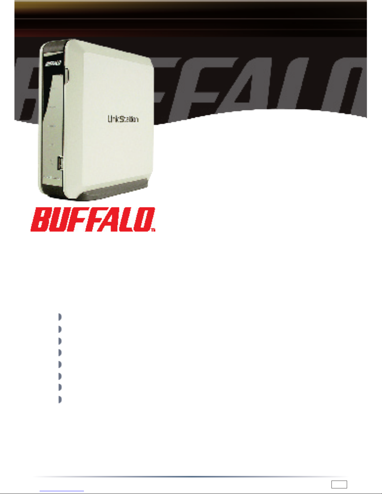
Unpacking and Setup
This section provides unpacking and setup information for LinkStation.
Open the shipping carton of LinkStation and carefully unpack its contents. The
carton should contain the following items:
Main unit (LinkStation) 1
LinkStation Base Plate 1
Base Rubber Feet 4
Ethernet Cable 1
Power Cord 1
LinkNavigator Installation CD 1
Quick Setup Guide (this user’s guide) 1
Warranty card 1
If any items are missing or damaged, please contact the reseller or retailer from
which the product was purchased.
The front face of the LinkStation has a protective plastic film covering for
protection from scratching during assembly and shipping. The film can be
removed by peeling it away from any corner of the front face.
Quick Setup Guide
LinkStation
HD-HGLAN Series
www.buffalo-technology.com
PY00-31003-DM20-01 1-01
Page 2
2
LinkStation Setup
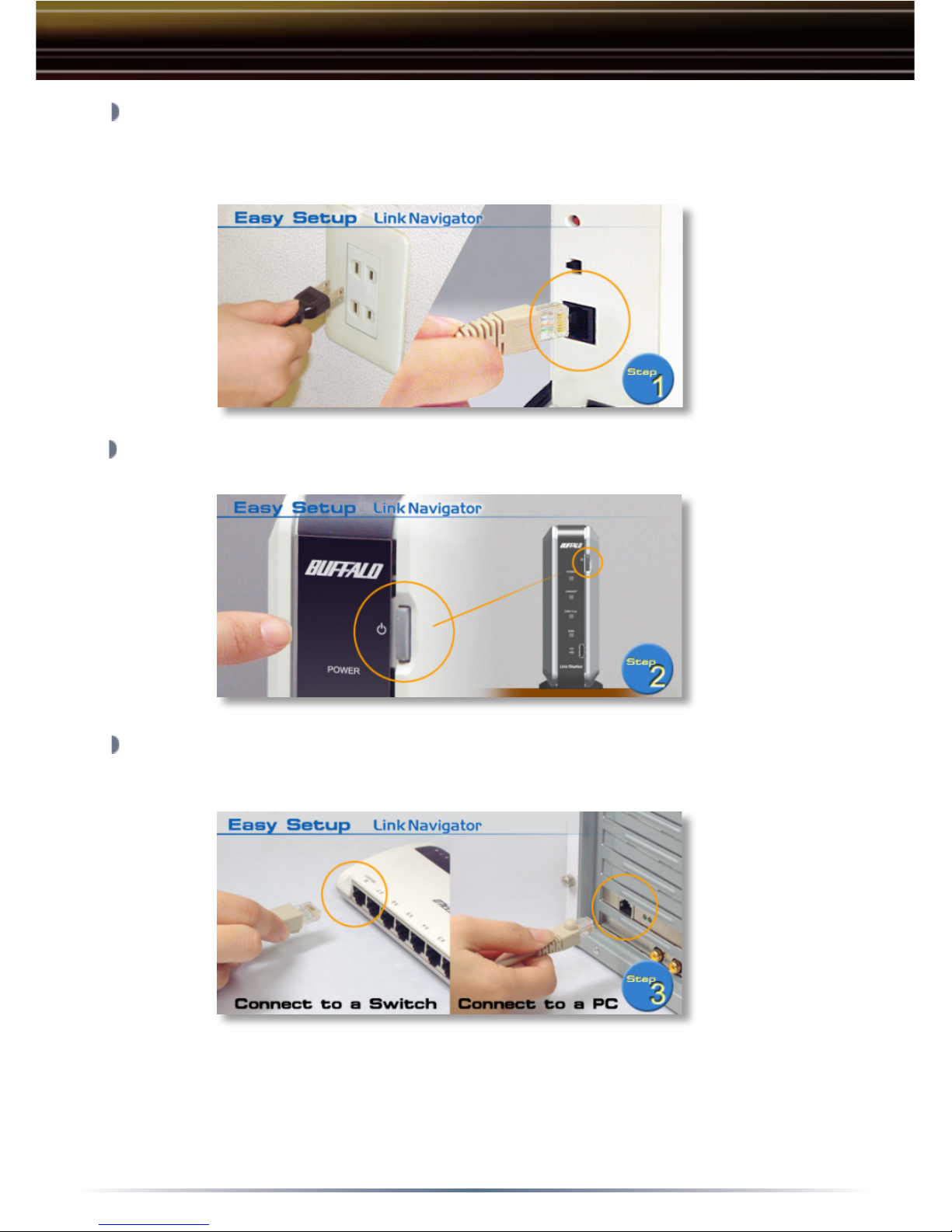
Plug LinkStation’s power cord into the back of LinkStation. Plug the other
end of the power code into a power outlet. Then, connect the included
Ethernet Cable into the Ethernet port on the back of LinkStation.
Press the power button on the front of LinkStation to turn LinkStation on.
Connect the other end of the included Ethernet Cable into a hub, switch,
or router on the network, or connect it directly to a nearby running PC.
NOTE:
It is recommended to connect LinkStation to a hub or switch
on the network. Connecting it directly to the back of a PC should only
be used if absolutely necessary. Many features including DHCP IP
Addressing require LinkStation to be connected to a switch or hub.
Page 3
3
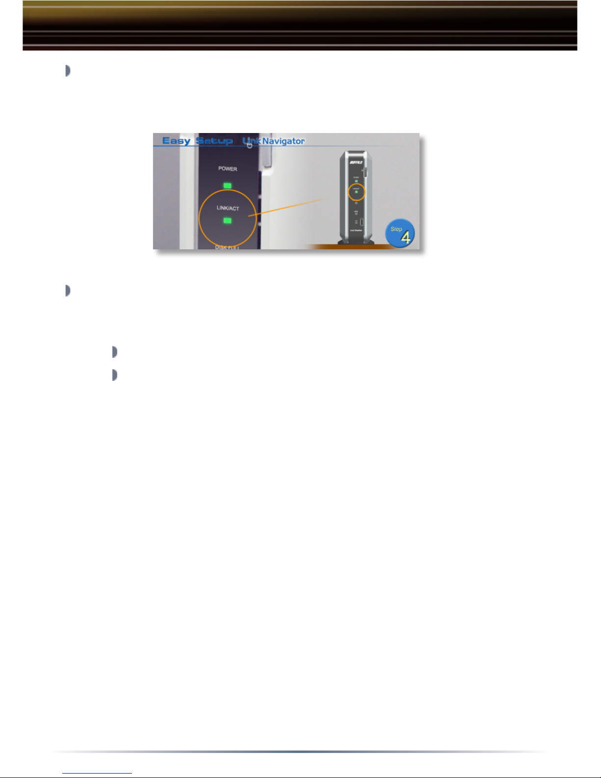
Check the LINK/ACT light on the front of the LinkStation. If it is lit, then
LinkStation is connected properly; please turn to Page 4 to continue
setup. If it is not lit, continue to the next step.
Verify that the LINK/ACT light on the front of LinkStation is lit (see
Step 4’s
picture). If it is lit, turn to Page 4 to contintue setting up LinkStation. If the
LINK/ACT light is still not lit, please verify the following:
Both LinkStation and the hub, switch, or PC are powered on.
The Ethernet Cable is securely fastened to both devices.
LinkStation Setup
Page 4

4
Insert the LinkNavigator CD
into the PC’s CD-ROM drive.
Depending on the PC’s
configuration, the EasySetup
program may launch. If
it does not automatically
launch, manually launch it
by pressing the ‘Start’ menu
and selecting the ‘Run...’
option. When the ‘Run’ dialog opens, type x:\easysetup.exe (where X
is the drive letter of the CD-ROM drive). Press ‘OK’ to continue.
Link Navigator is now running.
Please press the ‘Install IP Setup
Utility’ button, then press the
‘Start’ button.
The LinkStation IP Address
Configuration Utility will launch
and begin scanning for all
available LinkStation devices on
the network.
The IP Setup Utility allows you
to easily configure LinkStation’s
network settings. The
‘Search’
button will re-scan the network
for all available LinkStations. The
drop down menu lists all available
LinkStations. If there are multiple
LinkStations on the network, then
select the proper LinkStation from
the drop down menu. Once the
proper LinkStation has been selected from the drop down menu,
press the ‘Change IP Address’ button.
The setup of Link Navigator is performed using the following steps:
Link Navigator Setup
Page 5
5
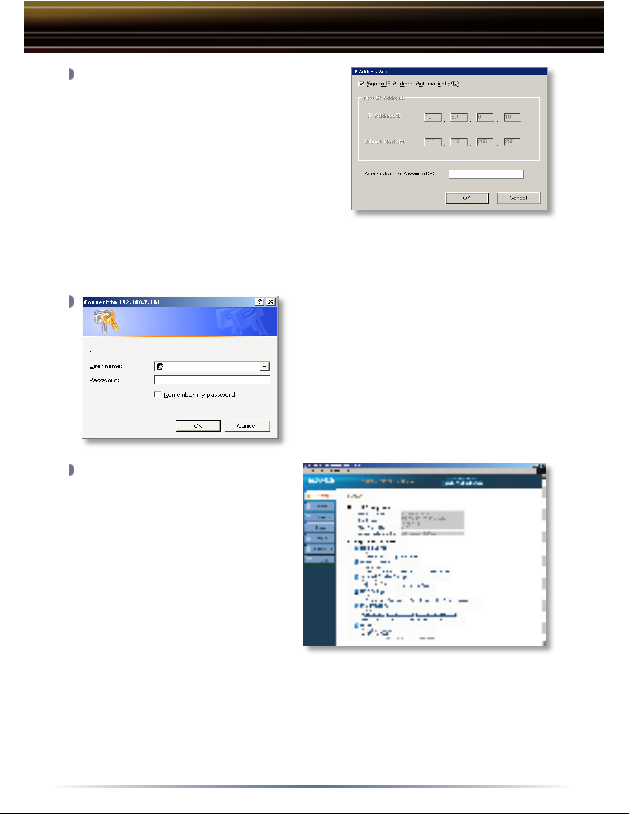
This part of the program changes
LinkStation’s IP Address. Check the
box that states ‘Acquire IP Address
Automatically’. This will give
LinkStation an IP Address from the
network’s router/DHCP server. A static
IP Address and gateway can also be
set if preferred. The
‘Administrator
Password’ field sets an administrator
password for the web-based configuration. If a password is desired,
then type a password in the field. When finished, press the
‘OK’
button. LinkStation will confirm and set the IP Address settings.
The login prompt will appear.
The user name is root.
There is NO password by default.
If a password was specified on the
previous step, then type that password
in the ‘Password’ field. Press the
‘OK’
button when finished.
These are LinkStation’s main
configuration menus. Please
bookmark this page so it
can be accessed for future
configuration changes.
Refer to the User Manual for
detailed explanations of each
menu and their settings. The
User Manual is located on the
LinkNavigaor CD-ROM.
Please not that Pcast media server option can only be used in
conjunction with a Buffalo LinkTheater.
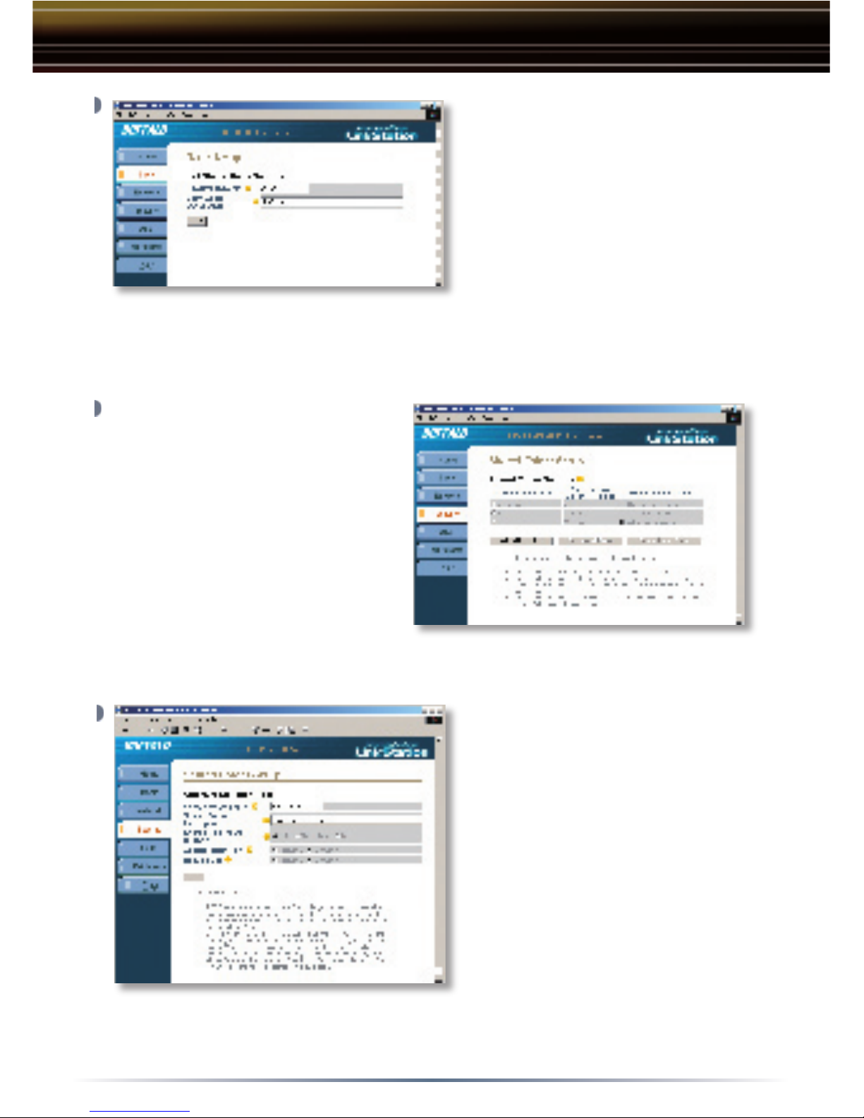
To continue setup, click on the
‘Basic’ settings button. This will allow
you to setup some important settings.
Then click on the ‘LinkStation Name Setup’ link.
Link Navigator Setup
Page 6
6
The LinkStation name
will be required to access
LinkStation. A friendly, easy
name is recommended.
Enter a suitable name in the
‘LinkStation Name’ field.
Feel free to use your first or
last name, a description of
the data to be installed on
LinkStation, or simply name it LinkStation. Enter a short description of
LinkStation in the ‘LinkStation Description’ field. Once completed,
press the ‘Apply’ button.
By default there are two shares
on LinkStation. If you would
like to create additional shares
for specific users or specific
types of data, then click on the
‘Security’ tab. Then click on
the ‘Shared Folder Setup’ link.
From this configuration page
you can add new shares or edit
existing shares.Press the ‘Add
a New Folder’ button to begin creating a new shared folder.
To begin setting up a new
share, enter an appropriate
share/folder name in the
‘Shared Folder Name’
field. Enter a description
of the share in the ‘Shared
Folder Description’ field. It
is recommended to leave the
remaining settings in their
default state. Please refer
to the User Manual on the
LinkNavigator CD-ROM before
changing any of these settings. Press the ‘Apply’ button when finished.
Please repeat this step to create additional shares.
LinkStation Configuration
Page 7
7
Accessing LinkStation data is performed using the following steps:
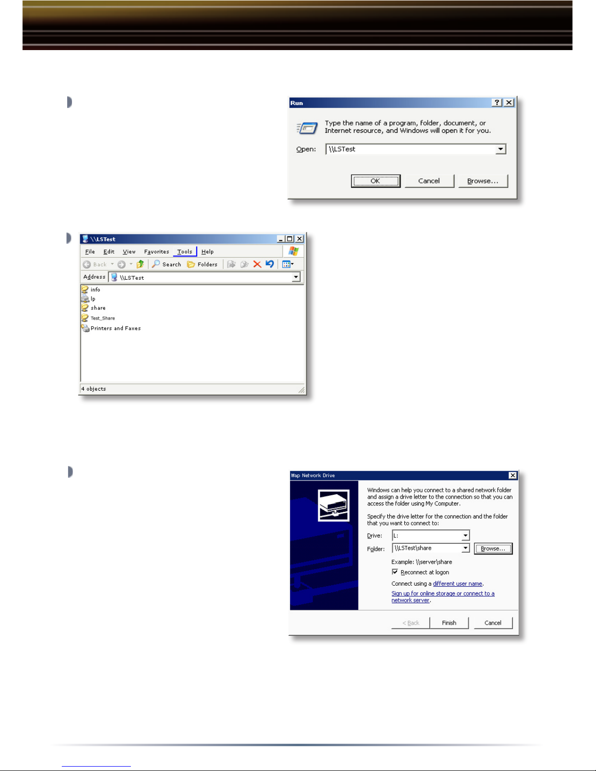
LinkStation’s ‘Root Directory’
will appear. You will see all
of the configured shares. All
users can read and write to all
folders. To setup security and
password protection, please
refer to the User Manual on the
LinkNavigator CD-ROM. Also,
please refer to the User Manual
to setup the print server. A
drive letter can also be mapped
for LinkStation, see the next step for more information. LinkStation can
be accessed by multiple computers simultaneously.
From the previous step’s ‘Root
Directory’ screen, use the pull
down menu and click ‘Tools’
and then select ‘Map Network
Drive’. The ‘Map Network
Drive’ program will run. Select
the drive letter you would like
LinkStation to assume from the
‘Drive:’ pull down menu. Enter
the \\LinkStation_Name\share_
name in the ‘Folder:’ field (where
LinkStation_Name is the ‘LinkStation Name’
and share_name is the
‘Shared Folder Name’
both set on Page 6). Once complete, check the
‘Reconnect at logon’ box and press the ‘Finish’ button.
Congratulations, LinkStation is setup. Please see the User Manual on
the LinkNavigator CD-ROM for more help and configuration options.
Press the ‘Start’ menu, select
the ‘Run...’ option. When the
‘Run’ dialog appears, please
type \\LinkStation_Name
(where LinkStation_Name is the
‘LinkStation Name’ set on
Page
6). Press ‘OK’ to continue.
Accessing LinkStation Data from a PC
Page 8

8
Technical Specifications
LAN Standards: IEEE 802.3u 100BASE-TX; IEEE 802.3
10BASE-T
Transmission Types: 1000Mbps/100Mbps/10Mbps;
(1000BASE-T) 8B1Q4+PAM5
(100BASE-T) 4B5B+MLT-3
(10BASE-T) Manchester Coding
Access Media: CSMA/CD
Media Interface: RJ-45
USB Standard: USB 2.0
Hi-Speed (HS)
Full-Speed (FS)
Low-Speed (LS)
USB Connector: USB A Connector (2)
Data Transmission Speed: Max: 480 Mbps (HS Mode)
Max: 12 Mbps (FS Mode)
Electric Current: 5.0V 1.5A, 12V 1.5A
Power Consumption: 17W Maximum
Dimensions: 2.4 x 6.94 x 7.4 in. (60 x 173.5 x 185 mm.)
Weight: 3.8 LB. (1.3 kg.)
Operating Temperature: 5-35 C; 20-80% non-condensing
Page 9

9
CE Mark Warning
This is a Class B product. In a domestic environment, this product may cause
radio interference, in which case the user may be required to take adequate
measures.
Technical Support
Buffalo Technology offers Technical Support between the hours of 9am-6pm
(GMT) Monday to Thursday and 9am-4:30pm (GMT) Friday for this product.
Customers in Europe can obtain Technical Support using the following
information:
◗ Online Help Available on the enclosed AirNavigator CD.
◗ Web www.buffalo-technology.com
◗ E-mail [email protected]
◗ Telephone UK only: 08712 50 12 60
Elsewhere: +353 61 708 050
The constantly evolving state of wireless products and operating systems requires
Buffalo Technology to occasionally release updated software to take advantage
of new technologies and to comply with industry standards. For the most recent
software, firmware, driver, and technical whitepaper releases available, please visit
the Buffalo Technology website: www.buffalo-technology.com
Page 10

10
MEMO
Page 11

11
MEMO
Page 12

12
BUFFALO WARRANTY STATEMENT
Buffalo products come with a 2-year limited warranty from the date of purchase.
Buffalo Technology warrants in good operating condition for the warranty period.
This warranty does not include non-Buffalo Technology installed components. If
the Buffalo product malfunctions during the warranty period, Buffalo Technology
will, at its discretion, repair or replace the product at no charge, provided the
product has not been subjected to misuse, abuse or non-Buffalo Technology
authorized alterations, modifications or repairs. When returning a product,
include your original proof of purchase. Return requests cannot be processed
without proof of purchase. Shipment of returned product to Buffalo Technology is
the responsibility of the purchaser. All expressed and implied warranties for the
Buffalo product line including, but not limited to, the warranties of merchantability
and fitness for a particular purpose, are limited in duration to the above period.
Under no circumstances shall Buffalo Technology be liable in any way to the
user for damages, including any lost profits, lost savings or other incidental or
consequential damages arising out of the use of, or inability to use, the Buffalo
products.
Buffalo Technology reserves the right to revise or update its products, software,
or documentation without obligation to notify any individual or entity.
Important Notice
Please have your proof of purchase receipt to get warranty support. All defective
products shall be returned with a copy of proof of purchase.
In no event shall Buffalo Technology’s liability exceed the price paid for the
product from direct, indirect, special, incidental, or consequential damages
resulting from the use of the product, its accompanying software, or its
documentation. Buffalo Technology does not offer refunds for any product.
BUFFALO TECHNOLOGY UK LTD
176, Buckingham Avenue,Slough, Berkshire, SL1 4RD United Kingdom
Tel: +44 (0) 1753 555000
Fax: +44 (0) 1753 535420
E-mail: [email protected]
Copyright © 2005 Buffalo Technology UK, Ltd. All Rights Reserved. - Buffalo Technology UK, Ltd. is
part of BUFFALO INC., the global manufacturers of IT peripherals, including memory, networking, and
multimedia products, inside many of the world’s computers. All trademarks are the property of their
respective owners.
Warranty Statement
 Loading...