

Buffalo FTD-G931AS, FTD-G931BK, FTD-G931AS/BK Service Manual

SERVICE MANUAL
FTD-G931AS
FTD-G931AS/BK
THESE DOCUMENTS ARE FOR REPAIR SERVICE INFORMATION ONLY.EVERY REASONABLE
EFFORT HAS BEEN MADE TO ENSURE THE ACCURACY OF THIS MANUAL; WE CANNOT GUARANTEE THE
ACCURACY OFTHIS INFORMATION AFTER THE DATE OF PUBLICATION AND DISCLAIMS RELIABILITY FOR
CHANGES, ERRORS OR OMISSIONS.

BUFFALO FTD-G931AS/BK
2
Table of Contents
Table of Contents ----------------------------------------------------------------------------------------------------------- 02
Revision List ------------------------------------------------------------------------------------------------------------------03
1. Monitor Specification ---------------------------------------------------------------------------------------------------04
2. LCD Monitor Description -----------------------------------------------------------------------------------------------05
3. Operation Instructions --------------------------------------------------------------------------------------------------06
3.1 General Instructions ------------------------------------------------------------------------------------------------06
3.2 Operation Instructions ----------------------------------------------------------------------------------------------06
3.3 Adjusting The Picture -----------------------------------------------------------------------------------------------07
4. Input/Output Specification ---------------------------------------------------------------------------------------------09
4.1 Input Signal Connector ---------------------------------------------------------------------------------------------09
4.2 Factory Preset Display Modes -----------------------------------------------------------------------------------09
4.3 Power Supply Requirements -------------------------------------------------------------------------------------10
4.4 Panel Specification-----------------------------------------------------------------------------------------------------11
5. Software Flow Chart -----------------------------------------------------------------------------------------------------14
6. Circuit Description ------------------------------------------------------------------------------------------------------15
7. Trouble Shooting ------------------------------------------------------------------------------------------------------- 16
7.1 Main Board ------------------------------------------------------------------------------------------------------------16
7.2 PWPC Board ----------------------------------------------------------------------------------------------------------19
8. Schematic ------------------------------------------------------------------------------------------------------------------21
8.1 Main Board ------------------------------------------------------------------------------------------------------------21
8.2 Inverter/Power Board ----------------------------------------------------------------------------------------------27
8.3 Key Pad Board ------------------------------------------------------------------------------------------------------29
8.4 Audio Board ------------------------------------------------------------------------------------------------------- --30
9. BOM List -------------------------------------------------------------------------------------------------------------31~48

BUFFALO FTD-G931AS/BK
3
Revision List
Revision Date Change Description
A00 Nov-01-04 T980KAXNJSB1A
A01 Mar.-14-06 T980KA4NJSB1A/T980KA4NJSB2A
BUFFALO FTD-G931AS/BK
4
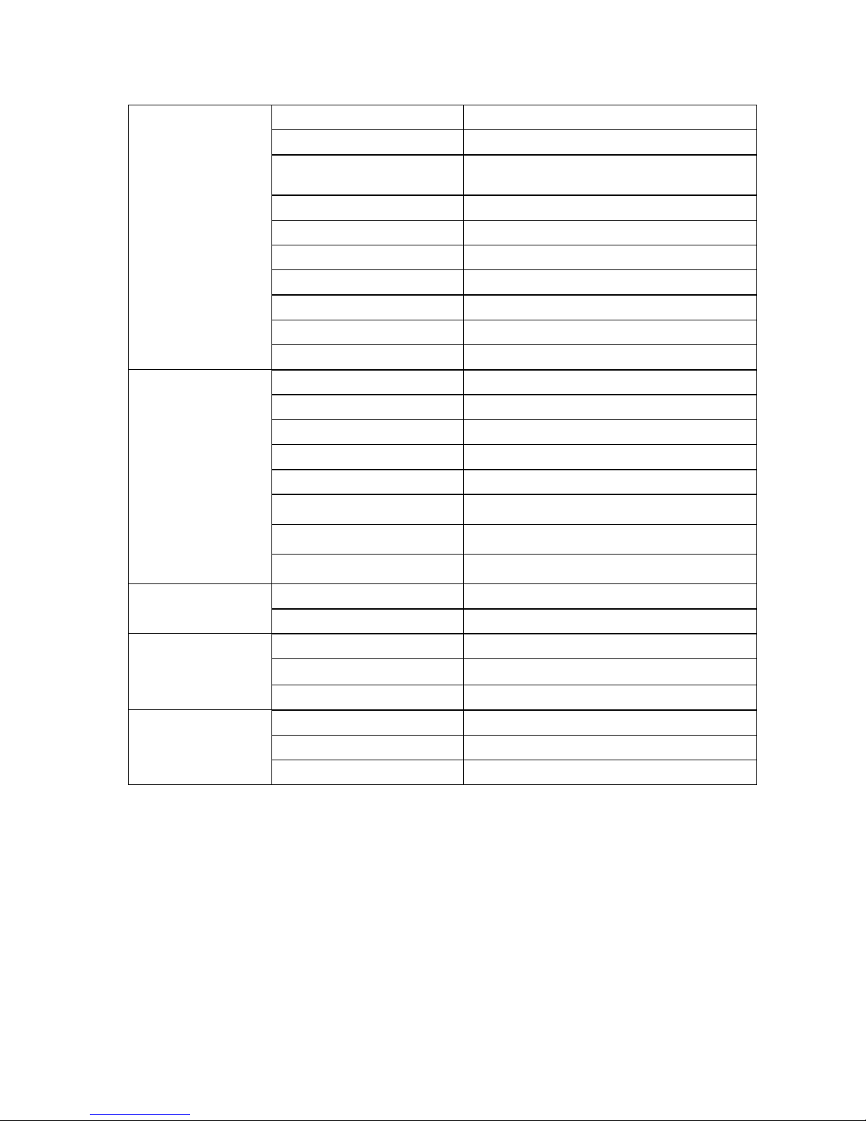
1.MONITOR SPECIFICATIONS
Driving system TFT LCD
Size 19.0"(48.18cm)
Active Area
Horizontal: 376.32mm
Vertical: 301.056mm
Panel AU M190EN03
Pixel pitch 0.294mm(H) x 0.294mm(V)
Viewing angle 170(H) 170(V) (CR>10)
Luminance
250 cd/m
2
(typ)
Contrast Ratio 800:1 (typ)
Response time 20ms (typ)
LCD Panel
Display colors 16.7M Colors
R G B 0.7Vp-p
H/V separate TTL level
DDC signals TTL level
Horizontal frequency 24kHz–80kHz
Vertical rate 55-75Hz
Resolutions 640 x 480 up to 1280 x 1024
Audio 3W x2
Input
AC voltage
100~240V (+/-10%) AC
Normal operation
≤27.5W
Power consumption
Power off
≤2W
Temperature 0-50°C
Humidity 15-90%
Operating condition
Altitude 12,000 feet
Temperature -20-60°C
Humidity 15-90%
Storage condition
Altitude 40,000 feet
BUFFALO FTD-G931AS/BK
5
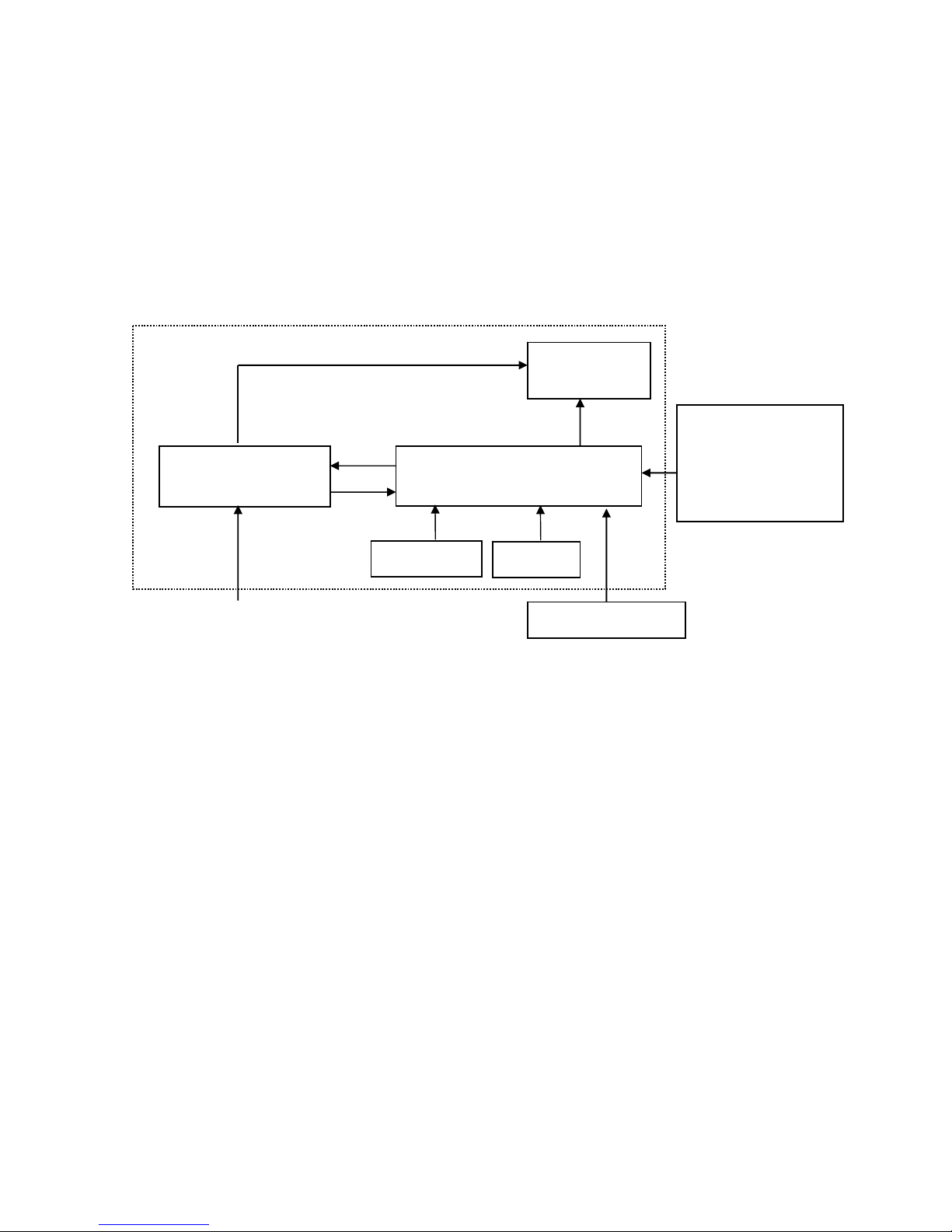
2.LCD MONITOR DESCRIPTION
The LCD MONITOR will contain an main board, an inverter/power board, an audio board, keypad board which house
the flat panel control logic, brightness control logic and DDC.
The power board will provide AC to DC Inverter voltage to drive the backlight of panel and the main board chips each
voltage.
Power board
(Include: inverter)
Flat Panel and
CCFL backlight
Main Board
Keyboard
RS232 Connector
For white balance
adjustment in factory
mode
HOST Computer
CCFL Drive.
AC-IN
100V-240V
Video signal, DDC
Monitor Block Diagram
Audio board
BUFFALO FTD-G931AS/BK
6
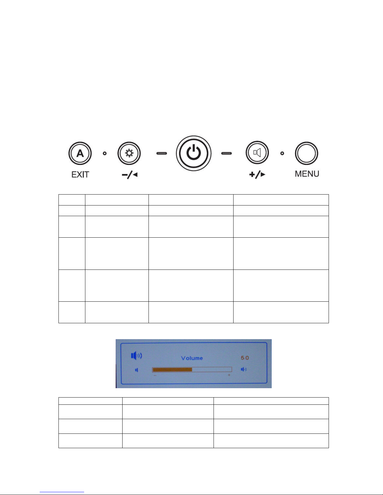
3. OPERATING INSTRUCTIONS
3.1 GENERAL INSTRUCTIONS
Press the power button to turn the monitor on or off. The other control buttons are located at front panel of
the monitor. By changing these settings, the picture can be adjusted to your personal preferences.
-
The power cord should be connected.
-
Connect the video cable from the monitor to the video card.
- Press the power button to turn on the monitor, the power indicator will light up.
3.2 OPERATING INSTRUCTIONS
NO. Within OSD Without OSD
1 Power Button Turn on/off Turn on/off
2 MENU Button
1.Enter the OSD sub menu
2.Select the OSD menu
Open OSD menu
3 Left Arrow/- Button
1.Move the cursor to left
2.Adjust down when menu
item selected
Open Bright menu
4 Right Arrow/+ Button
1.Move the cursor to left
2.Adjust down when menu
item selected
Open the Volume menu
5 Exit Button
1.Exit Sub menu
2. Exit the menu item
Run the Auto Adjust when this
button keep to push for 1 second
Hot keys
Button Function Remark
Left Arrow/- Button
To change the ECO mode and
MAX mode and User mode
The item adjust the power consumption to
change the luminance
Right Arrow/+ Button To Adjust the Volume
When Mute function is ON, if they change
the volume then mute function is off
Exit Button To run the Auto Adjust
When this button keep to push for 1
seconds
BUFFALO FTD-G931AS/BK
7
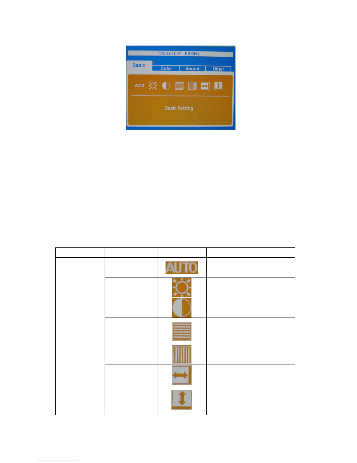
3.3 ADJUSTING THE PICTURE
Steps:
1.Press MENU button to display OSD main menu, Press Left button or Right button may select other main
Menu.
2. Press MENU button to adjust items of each main menu.
3. Press Left button or Right button may select item you wish to enter.
4. Press MENU button to enter, and press Left button or Right button to adjust item you select.
5. Press EXIT button may back previous menu.
6. Repeat steps 2-5 to adjust an additional item, or select the EXIT button to return to previous menu.
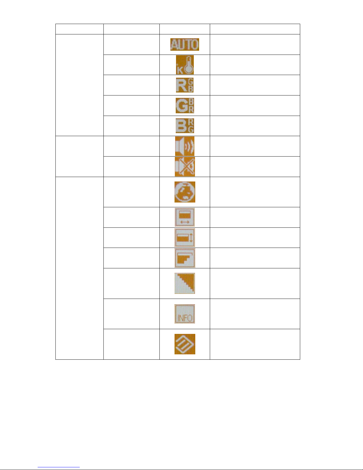
The description for control function:
Main Menu Item Sub Menu Item Sub Menu Icon Description
Auto
Auto Adjust the H/V Position,
Phase and Clock of picture
Brightness
Backlight Adjustment
Contrast
Contrast from Digital-register
Phase
Adjust Picture Phase to reduce
Horizontal-Line noise
Clock
Adjust picture Clock to reduce
Vertical-Line noise
H. Position
Adjust the horizontal position of
the picture
Basic
V. Position
Adjust the vertical position of the
picture
BUFFALO FTD-G931AS/BK
8
Main Menu Item Sub Menu Item Sub Menu Icon Description
Auto
Auto adjust color
Color Temp
Recall Color Temperature from
EEPROM
Red Setting
Red Gain from Digital-register
Green Setting
Green Gain from Digital-register
Color
Blue Setting
Blue Gain from Digital-register
Volume
Audio adjustment
Sound
Mute
Audio prohibition
OSD language
OSD language selection
(English or Japanese)
OSD H-Position
Adjust the horizontal position of
the OSD
OSD V-Position
Adjust the vertical position of the
OSD
OSD Transparency
OSD Transparency adjustment
Smoothing
Smoothing adjustment
Information
Show the resolution, H/V
frequency and input port of
current input timing
Other
Reset
Recall factory mode
BUFFALO FTD-G931AS/BK
9
4. INPUT/OUTPUT SPECFICATION
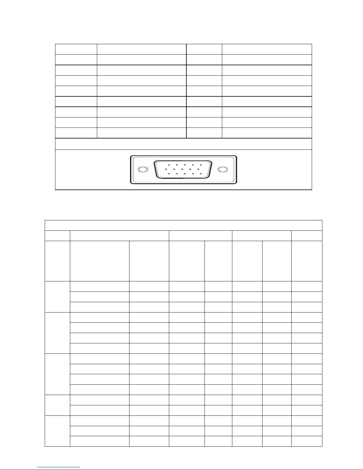
4.1 INPUT SIGNAL CONNECTOR
PIN NO. DESCRIPTION PI N NO. DESCRIPTION
1. Red 9. +5V
2. Green 10. Detect Cable
3. Blue 11. NC
4. Ground 12. DDC-Serial Data
5. Ground 13. H-Sync
6. R-Ground 14. V-Sync
7. G-Ground 15. DDC-Serial Clock
8. B-Ground
VGA Connector layout
15
6
10
11 15
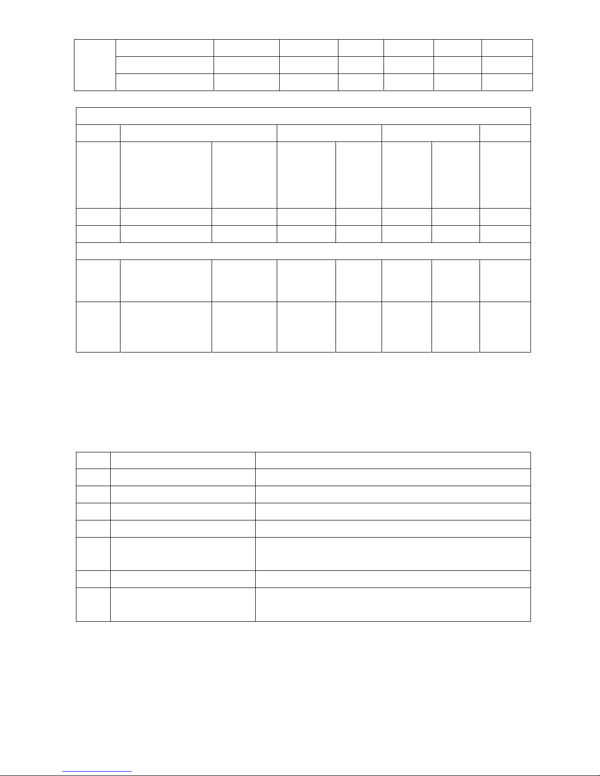
4.2 FACTORY PRESET DISPLAY MODES:
VESA MODES
Horizontal Vertical
Mode Resolution Total
Nominal
Frequency
+/- 0.5kHz
Sync
Polarity
Nominal
Freq.
+/- 1 Hz
Sync
Polarity
Nominal
Pixel
Clock
(MHz)
640x480@60Hz 800 x 525 31.469 N 59.940 N 25.175
640x480@72Hz 832 x 520 37.861 N 72.809 N 31.500
VGA
640x480@75Hz 840 x 500 37.500 N 75.00 N 31.500
800x600@56Hz 1024 x 625 35.156 N/P 56.250 N/P 36.000
800x600@60Hz 1056 x 628 37.879 P 60.317 P 40.000
800x600@72Hz 1040 x 666 48.077 P 72.188 P 50.000
SVGA
800x600@75Hz 1056x625 46.875 P 75.000 P 49.500
1024x768@60Hz 1344x806 48.363 N 60.004 N 65.000
1024x768@70Hz 1328x806 56.476 N 70.069 N 75.000
1024x768@75Hz 1312x800 60.023 P 75.029 P 78.750
XGA
1024x768@72Hz 1304x798 57.7 P 72 P 78.4
1024x768@75Hz 1326x804 60.2 P 75 P 80 Mac
1152x870@75Hz 1456x915 68.7 P 75 P 100
1152x864@75Hz 1600x900 67.5 P 75 P 108
1280x1024@60Hz 1688x1066 63.981 P 60.020 P 108.000
SXGA
1280x1024@75Hz 1688x1066 79.976 P 75.025 P 135.000
BUFFALO FTD-G931AS/BK
10
1280x960@60Hz 1800x1000 60 P 60 P 108
1280x1024@70Hz 1720x1064 74.4 P 70 P 124.9
1280x1024@72Hz 1724x1066 77.9 P 72 P 134.6
IBM MODES
Horizontal Vertical
Mode Resolution Total
Nominal
Frequency
+/- 0.5kHz
Sync
Polarity
Nominal
Freq.
+/- 1 Hz
Sync
Polarity
Nominal
Pixel
Clock
(MHz)
DOS* 720x400@70Hz 900 x 449 31.469 N 70.087 P 28.322
DOS 640x350@70Hz 800 x 449 31.469 P 70.087 N 25.175
MAC MODES
VGA 640x480@67Hz 864x525 35.000 N 66.667 N 30.240
SVGA 832x624@75Hz 1152x667 49.725 N 74.551 N 57.2832
Note: All modes will automatically optimize the screen size with “ AUTO-config “ function, except 4 dos- modes:
640x480@60hz, 720z400@70hz, 640x350@70hz, and 640x400@70hz
4.3 POWER SUPPLY REQUIREMENT
NO. PARAMETER Description
1 A/C Line voltage range 100 V ~ 240 V
2 A/C Line frequency range
50 ± 3Hz, 60 ± 3Hz
3 Input Voltage transients
280 volts AC for 10 sec @40℃
4 Current 1.5A max at 100V; 0.8A max at 240 V
5 Peak surge current
< 60A peak at 240 VAC and cold starting
< 30A peak at 120VAC and cold starting
6 Leakage current < 3.5mA
7 Power line surge
No advance effects (no loss of information or defect)
With a maximum of 1 half-wave missing per second
BUFFALO FTD-G931AS/BK
11
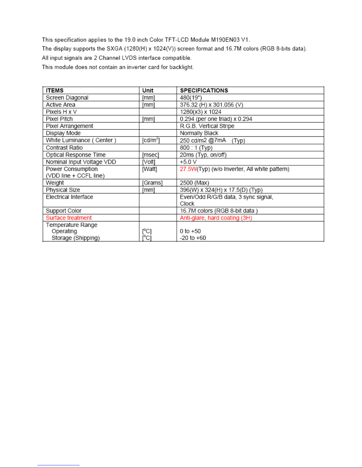
4.4 Panel Specification
4.4.1 General Feature
BUFFALO FTD-G931AS/BK
12
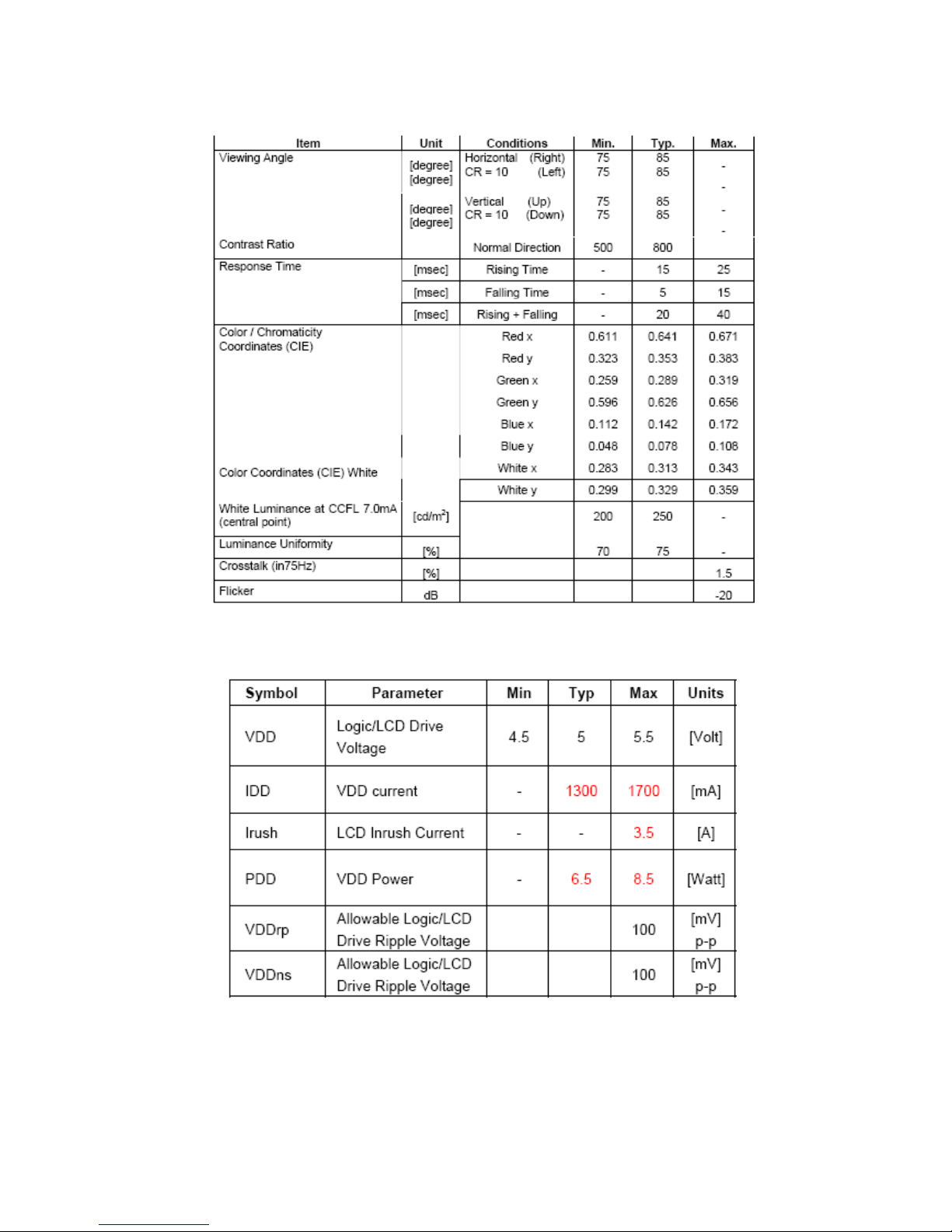
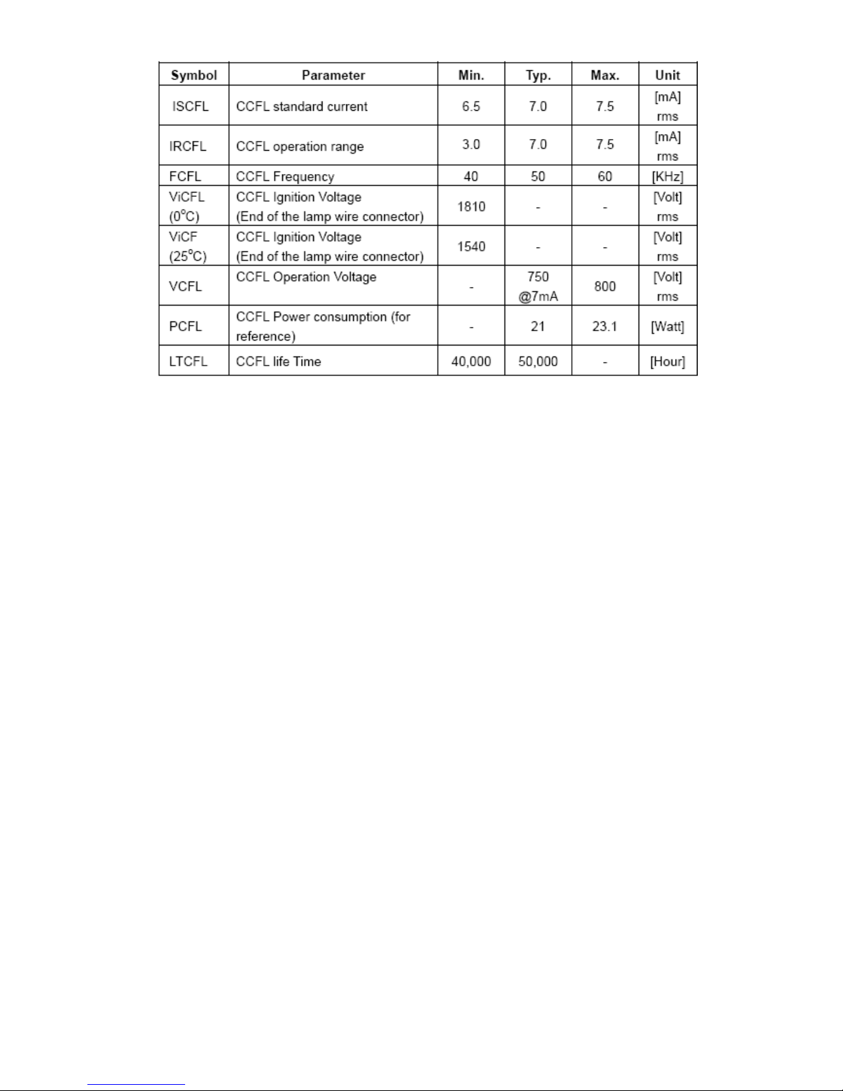
4.4.2 Optical Characteristics
4.4.3 Electrical Characteristics
BUFFALO FTD-G931AS/BK
13
BUFFALO FTD-G931AS/BK
14
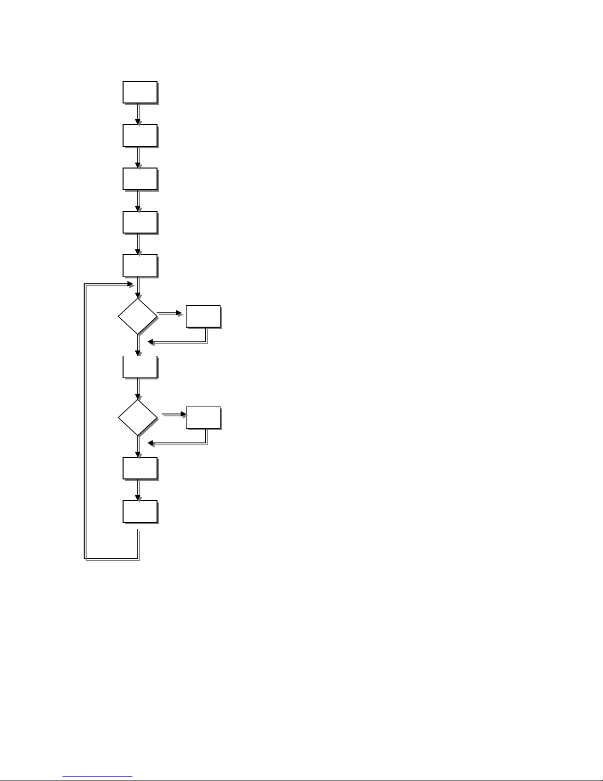
5. SOFTWARE FLOW CHART
(1)
(2)
(3)
(4)
(5)
(7)
(6)
(8)
(10)
(11)
(12)
(9)
Y
N
Y
N
1. Initialize MCU settings, including I/O, Timer, ISR and Serial
Port settings.
2. Read EEPROM content to recover monitor settings,
including brightness, contrast, color temperature and OSD
position etc.
3. Initialize system variable, including system flag, OSD
timeout counter, burin mode status… etc.
4. Initialize OSD menu variable for user operation
5. Initialize device on the board, now only MST scalar chip will
be initialized
6. Check if system is in power off status from first AC power
up. If yes, then go to 7, else go to 8.
7. If yes, system will be forced to enter power off status Mode
detection
8. Check if input timing has been changed, if yes then go to
10, else go to 11
9. Setup MST scalar for display according input timing
10. OSD handler for OSD operation.
Debug handler, only debug only
 Loading...