

Buffalo FTD-G731AS, FTD-G731BK, FTD-G731AS/BK Service Manual

SERVICE MANUAL
FTD-G731AS
FTD-G731AS/BK
THESE DOCUMENTS ARE FOR REPAIR SERVICE INFORMATION ONLY.EVERY REASONABLE
EFFORT HAS BEEN MADE TO ENSURE THE ACCURACY OF THIS MANUAL; WE CANNOT GUARANTEE THE
ACCURACY OFTHIS INFORMATION AFTER THE DATE OF PUBLICATION AND DISCLAIMS RELIABILITY FOR
CHANGES, ERRORS OR OMISSIONS.
MANUFACTURE DATA:Nov-01-2004

BUFFALO Service Manual
2
Table of Contents
Table of Contents ------------------------------------------------------------------------------ 02
Revision List -------------------------------------------------------------------------------------03
1. Monitor Specification ---------------------------------------------------------------------04
2. LCD Monitor Description ---------------------------------------------------------------05
3. Operation Instructions --------------------------------------------------------------------06
3.1 General Instructions ------------------------------------------------------------------06
3.2 Operation Instructions ------------------------------------------------------------------06
3.3 Adjusting The Picture ----------------------------------------------------------------07
4. Input/Output Specification ---------------------------------------------------------------09
4.1 Input Signal Connector --------------------------------------------------------------09
4.2 Factory Preset Display Modes -----------------------------------------------------09
4.3 Power Supply Requirements -------------------------------------------------------10
5. Software Flow Chart -----------------------------------------------------------------------------11
6. Circuit Description ------------------------------------------------------------------------------------------------------12
6.1 Block Diagram --------------------------------------------------------------------12
6.2 Introduction of main IC --------------------------------------------------------------13
7. Trouble Shooting -------------------------------------------------------------------------------------------------------16
7.1 Main Board ------------------------------------------------------------------------16
7.2 PWPC Board --------------------------------------------------------------19
8. Schematic ------------------------------------------------------------------------------------------------------------------21
8.1 Main Board ----------------------------------------------------------------------------------------------------------21
8.2 Inverter/Power Board --------------------------------------------------------------------------------------------26
8.3 Key Pad Board -----------------------------------------------------------------------------------------------------28
8.4 Audio Board ------------------------------------------------------------------------------------------------------- 28
9. BOM List -------------------------------------------------------------------------------------------------------------30~55

BUFFALO Service Manual
3
Revision List
Revision Date Change Description TPV model name
A00 Nov-01-04 Initial release
A01 Mar-13-06 Change the Main Board T780KA4NJSB1A/T780KA4NJSB2A
BUFFALO Service Manual
4
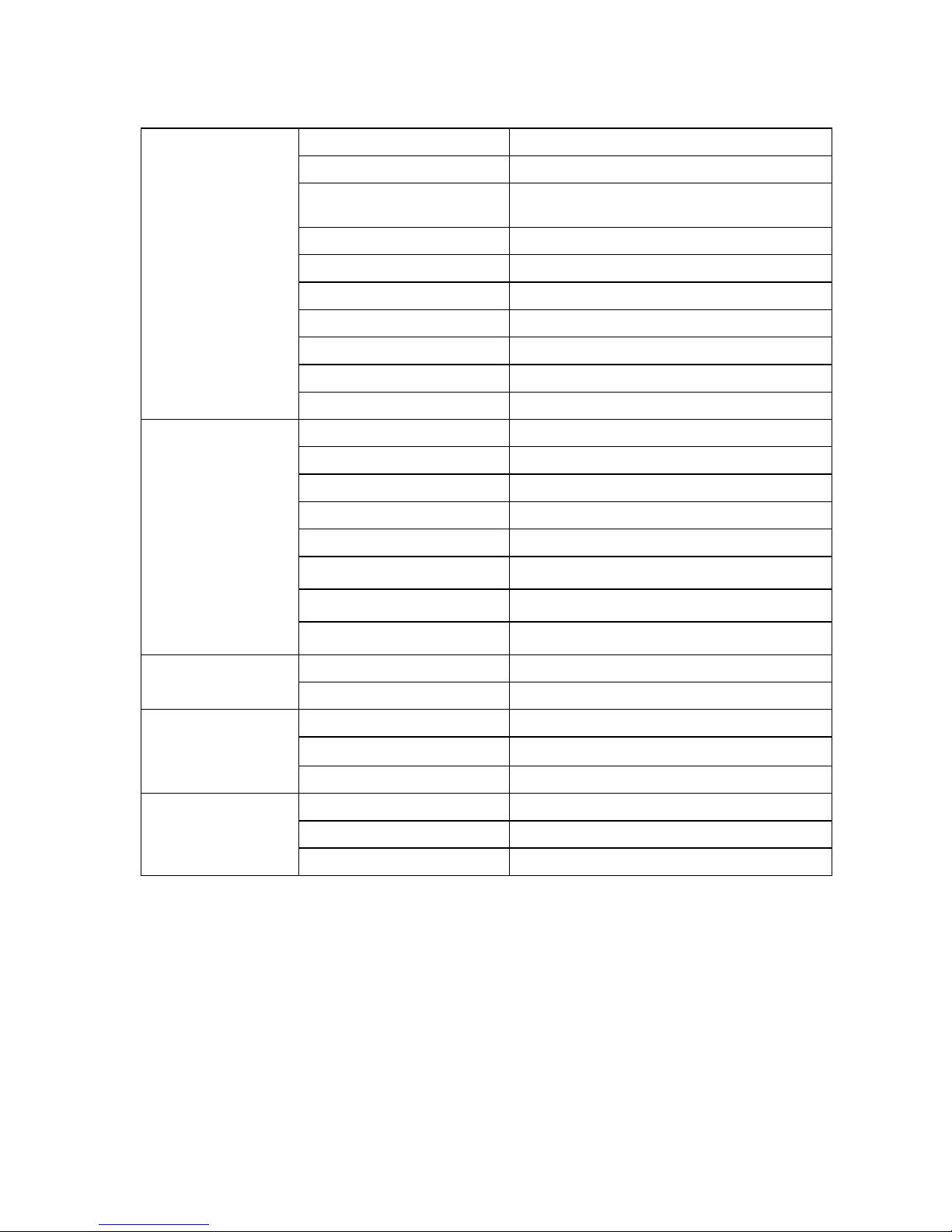
1.MONITOR SPECIFICATIONS
Driving system TFT LCD
Size 17.0"(43.2cm)
Active Area
Horizontal: 337.920mm
Vertical: 270.336mm
Panel AU M170EG01
Pixel pitch 0.264mm(H) x 0.264mm(V)
Viewing angle 140(H) 130(V) (CR>10)
Luminance
260 cd/m
2
(typ)
Contrast Ratio 450:1 (typ)
Response time 16ms (typ)
LCD Panel
Display colors 16.2 million Colors
R G B 0.7Vp-p
H/V separate TTL level
DDC signals TTL level
Horizontal frequency 24kHz–80kHz
Vertical rate 55-75Hz
Resolutions 640 x 480 up to 1280 x 1024
Audio 1.2W x2
Input
AC voltage
100~240V (+/-10%) AC
Normal operation
≤39W
Power consumption
Power off
≤2W
Temperature 0-35°C
Humidity 15-90%
Operating condition
Altitude 12,000 feet
Temperature -20-60°C
Humidity 15-90%
Storage condition
Altitude 40,000 feet
BUFFALO Service Manual
5
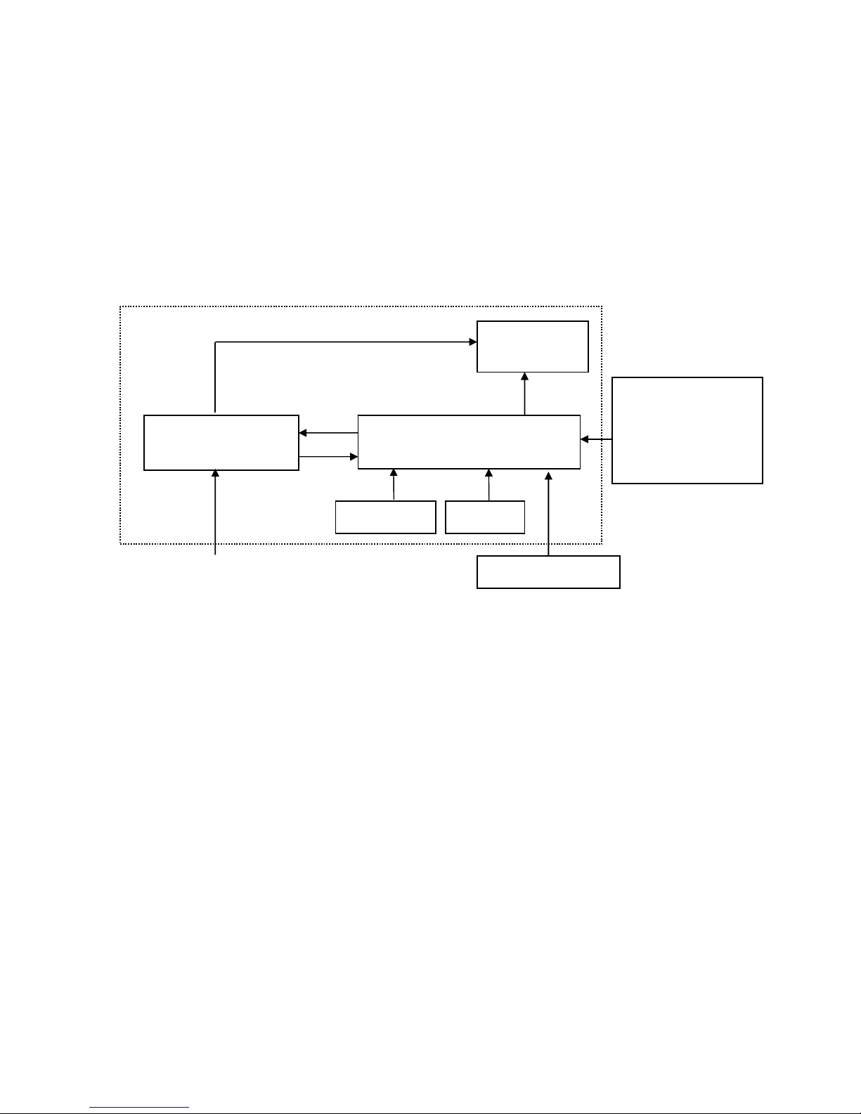
2.LCD MONITOR DESCRIPTION
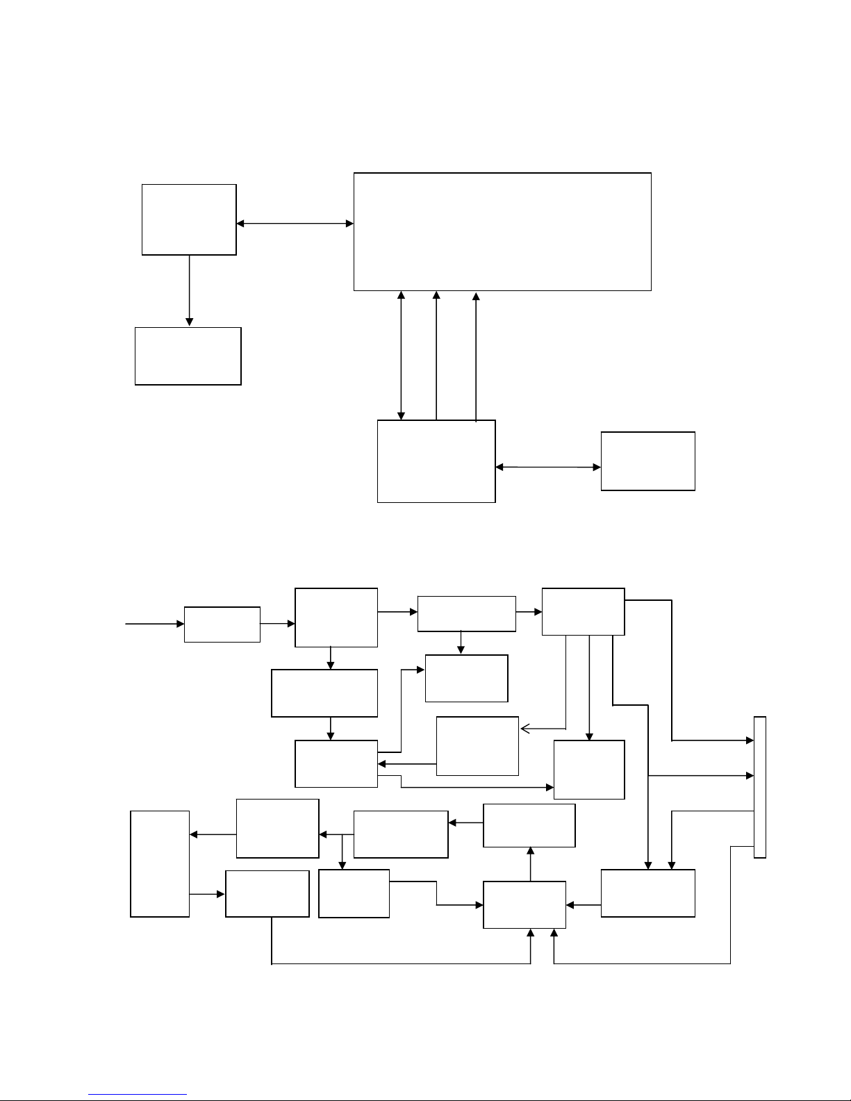
The LCD MONITOR will contain an main board, an inverter/power board, an audio board, keypad board which
house the flat panel control logic, brightness control logic and DDC.
The power board will provide AC to DC Inverter voltage to drive the backlight of panel and the main board chips
each voltage.
Power board
(Include: inverter)
Flat Panel and
CCFL backlight
Main Board
Keyboard
RS232 Connector
For white balance
adjustment in factory
mode
HOST Computer
CCFL Drive.
AC-IN
100V-240V
Video signal, DDC
Monitor Block Diagram
Audio board
BUFFALO Service Manual
6
3. OPERATING INSTRUCTIONS
3.1 GENERAL INSTRUCTIONS
Press the power button to turn the monitor on or off. The other control buttons are located at front panel of
the monitor. By changing these settings, the picture can be adjusted to your personal preferences.
-
The power cord should be connected.
-
Connect the video cable from the monitor to the video card.
- Press the power button to turn on the monitor, the power indicator will light up.
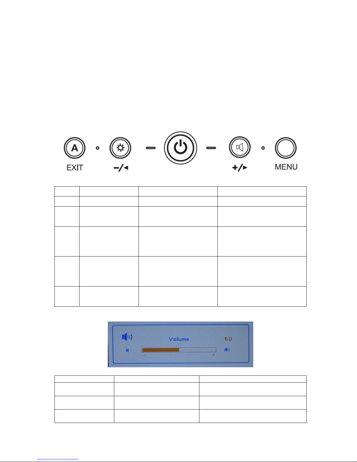
3.2 OPERATING INSTRUCTIONS
NO. Within OSD Without OSD
1 Power Button Turn on/off Turn on/off
2 MENU Button
1.Enter the OSD sub menu
2.Select the OSD menu
Open OSD menu
3 Left Arrow/- Button
1.Move the cursor to left
2.Adjust down when menu
item selected
Open Bright menu
4 Right Arrow/+ Button
1.Move the cursor to left
2.Adjust down when menu
item selected
Open the Volume menu
5 Exit Button
1.Exit Sub menu
2. Exit the menu item
Run the Auto Adjust when this
button keep to push for 1 second
Hot keys
Button Function Remark
Left Arrow/- Button
To change the ECO mode and
MAX mode and User mode
The item adjust the power consumption to
change the luminance
Right Arrow/+ Button To Adjust the Volume
When Mute function is ON, if they change
the volume then mute function is off
Exit Button To run the Auto Adjust
When this button keep to push for 1
seconds
BUFFALO Service Manual
7
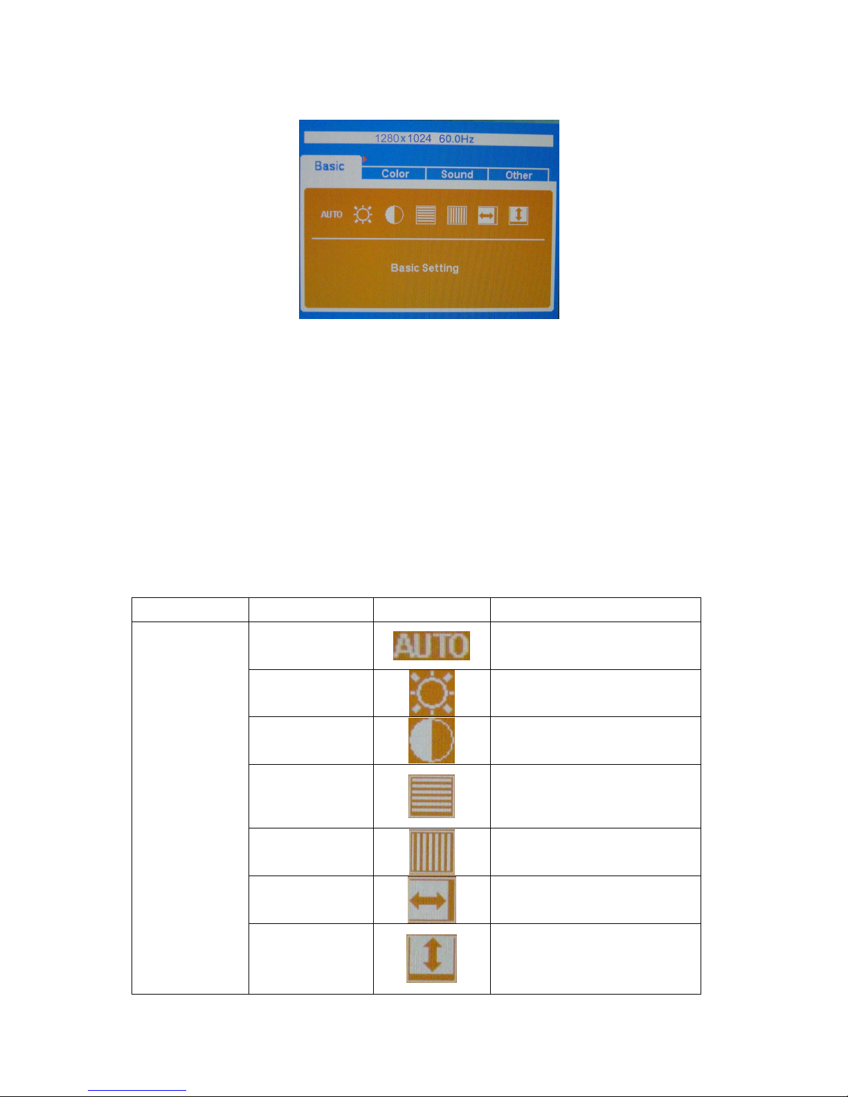
3.3 ADJUSTING THE PICTURE
Steps:
1.Press MENU button to display OSD main menu, Press Left button or Right button may select other main
Menu.
2. Press MENU button to adjust items of each main menu.
3. Press Left button or Right button may select item you wish to enter.
4. Press MENU button to enter, and press Left button or Right button to adjust item you select.
5. Press EXIT button may back previous menu.
6. Repeat steps 2-5 to adjust an additional item, or select the EXIT button to return to previous menu.
The description for control function:
Main Menu Item Sub Menu Item Sub Menu Icon Description
Auto
Auto Adjust the H/V Position,
Phase and Clock of picture
Brightness
Backlight Adjustment
Contrast
Contrast from Digital-register
Phase
Adjust Picture Phase to reduce
Horizontal-Line noise
Clock
Adjust picture Clock to reduce
Vertical-Line noise
H. Position
Adjust the horizontal position of
the picture
Basic
V. Position
Adjust the vertical position of the
picture
BUFFALO Service Manual
8
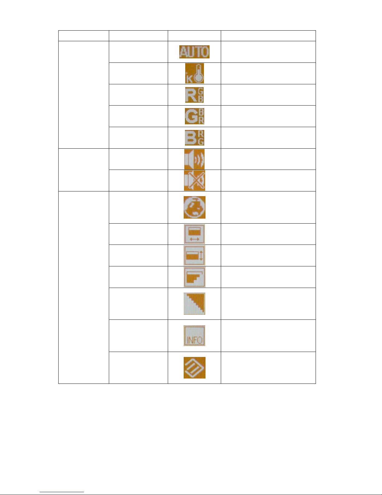
Main Menu Item Sub Menu Item Sub Menu Icon Description
Auto
Auto adjust color
Color Temp
Recall Color Temperature from
EEPROM
Red Setting
Red Gain from Digital-register
Green Setting
Green Gain from Digital-register
Color
Blue Setting
Blue Gain from Digital-register
Volume
Audio adjustment
Sound
Mute
Audio prohibition
OSD language
OSD language selection
(English or Japanese)
OSD H-Position
Adjust the horizontal position of
the OSD
OSD V-Position
Adjust the vertical position of the
OSD
OSD Transparency
OSD Transparency adjustment
Smoothing
Smoothing adjustment
Information
Show the resolution, H/V
frequency and input port of
current input timing
Other
Reset
Recall factory mode
BUFFALO Service Manual
9
4. INPUT/OUTPUT SPECFICATION
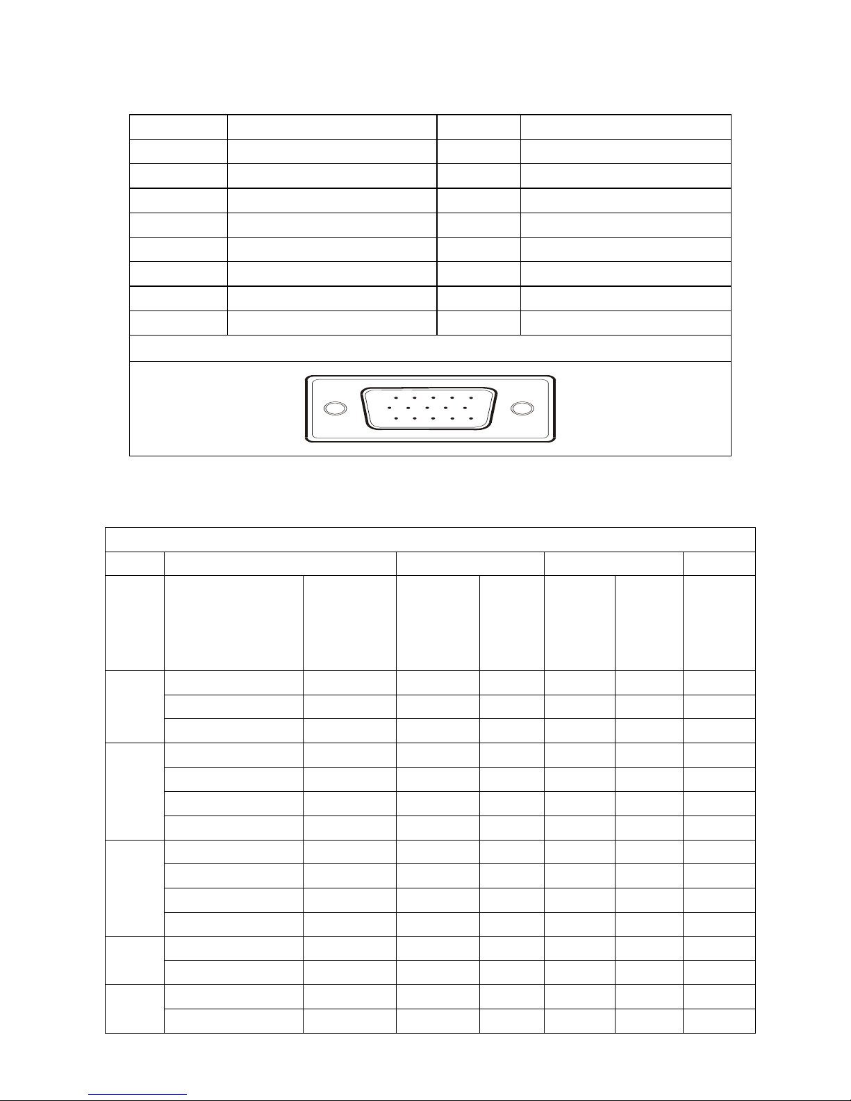
4.1 INPUT SIGNAL CONNECTOR
PIN NO. DESCRIPTION PIN NO. DESCRIPTION
1. Red 9. +5V
2. Green 10. Detect Cable
3. Blue 11. NC
4. Ground 12. DDC-Serial Data
5. Ground 13. H-Sync
6. R-Ground 14. V-Sync
7. G-Ground 15. DDC-Serial Clock
8. B-Ground
VGA Connector layout
15
6
10
11 15
4.2 FACTORY PRESET DISPLAY MODES:
VESA MODES
Horizontal Vertical
Mode Resolution Total
Nominal
Frequency
+/- 0.5kHz
Sync
Polarity
Nominal
Freq.
+/- 1 Hz
Sync
Polarity
Nominal
Pixel
Clock
(MHz)
640x480@60Hz 800 x 525 31.469 N 59.940 N 25.175
640x480@72Hz 832 x 520 37.861 N 72.809 N 31.500
VGA
640x480@75Hz 840 x 500 37.500 N 75.00 N 31.500
800x600@56Hz 1024 x 625 35.156 N/P 56.250 N/P 36.000
800x600@60Hz 1056 x 628 37.879 P 60.317 P 40.000
800x600@72Hz 1040 x 666 48.077 P 72.188 P 50.000
SVGA
800x600@75Hz 1056x625 46.875 P 75.000 P 49.500
1024x768@60Hz 1344x806 48.363 N 60.004 N 65.000
1024x768@70Hz 1328x806 56.476 N 70.069 N 75.000
1024x768@75Hz 1312x800 60.023 P 75.029 P 78.750
XGA
1024x768@72Hz 1304x798 57.7 P 72 P 78.4
1024x768@75Hz 1326x804 60.2 P 75 P 80 Mac
1152x870@75Hz 1456x915 68.7 P 75 P 100
1152x864@75Hz 1600x900 67.5 P 75 P 108 SXGA
1280x1024@60Hz 1688x1066 63.981 P 60.020 P 108.000
BUFFALO Service Manual
10
1280x1024@75Hz 1688x1066 79.976 P 75.025 P 135.000
1280x960@60Hz 1800x1000 60 P 60 P 108
1280x1024@70Hz 1720x1064 74.4 P 70 P 124.9
1280x1024@72Hz 1724x1066 77.9 P 72 P 134.6
IBM MODES
Horizontal Vertical
Mode Resolution Total
Nominal
Frequency
+/- 0.5kHz
Sync
Polarity
Nominal
Freq.
+/- 1 Hz
Sync
Polarity
Nominal
Pixel
Clock
(MHz)
DOS* 720x400@70Hz 900 x 449 31.469 N 70.087 P 28.322
DOS 640x350@70Hz 800 x 449 31.469 P 70.087 N 25.175
MAC MODES
VGA 640x480@67Hz 864x525 35.000 N 66.667 N 30.240
SVGA 832x624@75Hz 1152x667 49.725 N 74.551 N 57.2832
Note: All modes will automatically optimize the screen size with “ AUTO-config “ function, except 4 dos- modes:
640x480@60hz, 720z400@70hz, 640x350@70hz, and 640x400@70hz
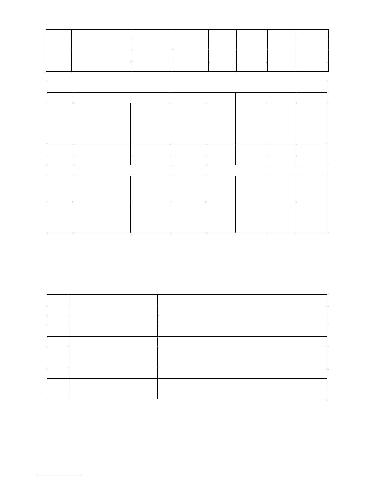
4.3 POWER SUPPLY REQUIREMENT
NO. PARAMETER Description
1 A/C Line voltage range 100 V ~ 240 V
2 A/C Line frequency range
50 ± 3Hz, 60 ± 3Hz
3 Input Voltage transients
280 volts AC for 10 sec @40℃
4 Current 1.5A max at 100V; 0.8A max at 240 V
5 Peak surge current
< 60A peak at 240 VAC and cold starting
< 30A peak at 120VAC and cold starting
6 Leakage current < 3.5mA
7 Power line surge
No advance effects (no loss of information or defect)
With a maximum of 1 half-wave missing per second
BUFFALO Service Manual
11
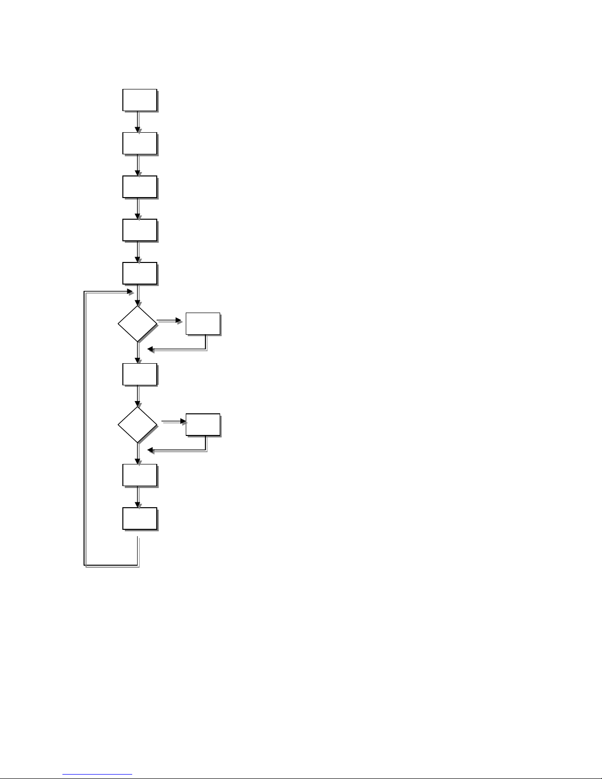
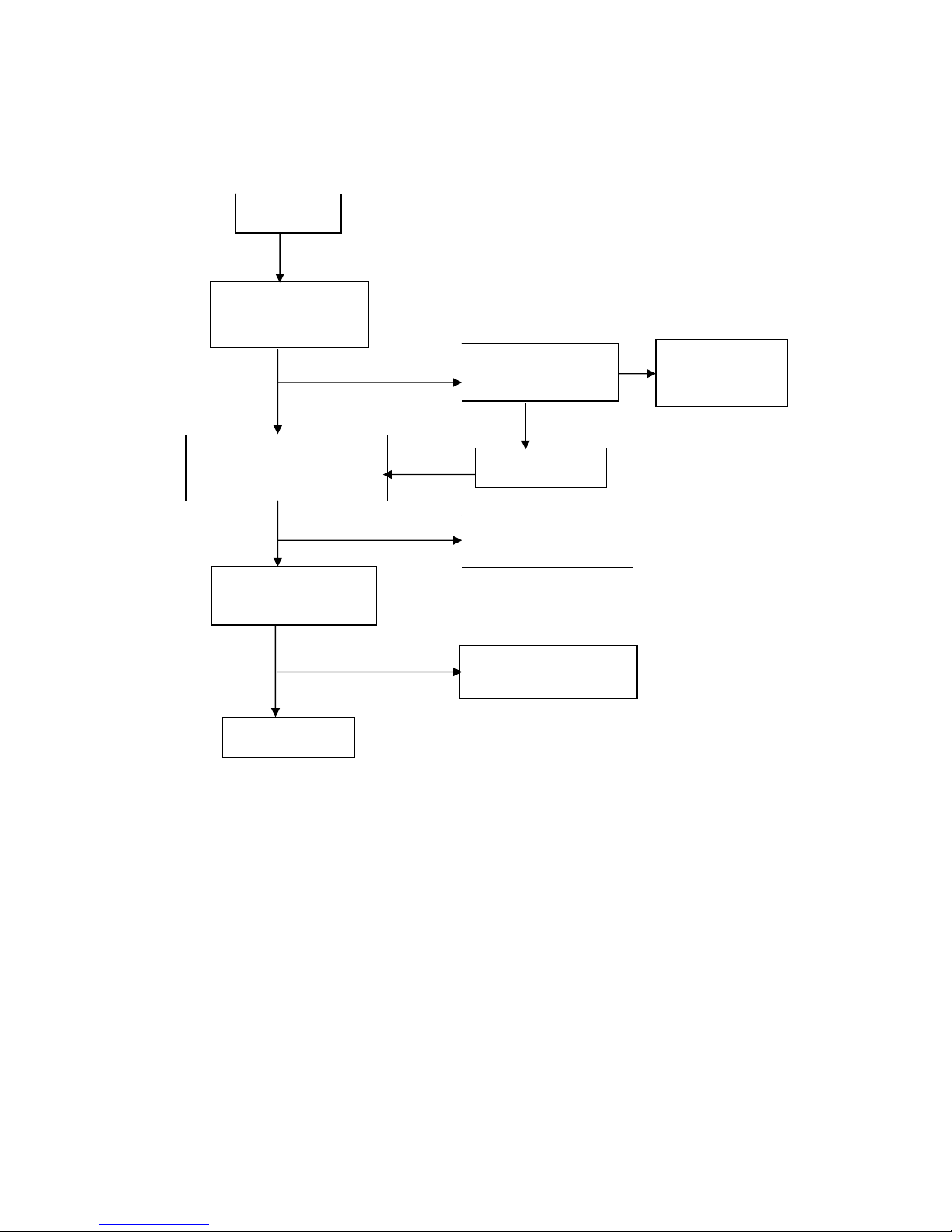
5. SOFTWARE FLOW CHART
(1)
(2)
(3)
(4)
(5)
(7)
(6)
(8)
(10)
(11)
(12)
(9)
Y
N
Y
N
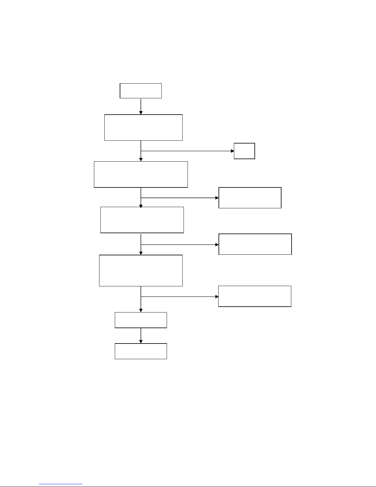
1. Initialize MCU settings, including I/O, Timer, ISR and Serial
Port settings.
2. Read EEPROM content to recover monitor settings,
including brightness, contrast, color temperature and OSD
position etc.
3. Initialize system variable, including system flag, OSD
timeout counter, burin mode status… etc.
4. Initialize OSD menu variable for user operation
5. Initialize device on the board, now only MST scalar chip will
be initialized
6. Check if system is in power off status from first AC power
up. If yes, then go to 7, else go to 8.
7. If yes, system will be forced to enter power off status Mode
detection
8. Check if input timing has been changed, if yes then go to
10, else go to 11
9. Setup MST scalar for display according input timing
10. OSD handler for OSD operation.
Debug handler, only debug only
BUFFALO Service Manual
12
6. Circuit Diagram
6.1 BLOCK DIAGRAM
MCU
Scalar TSU16AK-LFT
(Include ADC, OSD)
EEPROM
M24C16
D-Sub
Connector
EEPROM
M24C02
H sync
V sync
RGB
RXD
TXD
DB15_SDA
DB15_SCL
EPR_SDA
EPR_SCL
Main Board
EMI filter
Bridge
Rectifier
and Filter
Start Circuit
R906、R907
PWM
Control IC
Transformer
Over
Voltage
Protect
MOSFET
Q903
Rectifier
CMOS
Voltage
Feedback
Circuit
AC input
5V
12V
ON/OFF
Control
PWM
Control IC
Feedback
Circuit
OSC and
Output
Circuit
DC Convert
Circuit
MOSFET
Q203/Q204
Over
Voltage
Lamp
ON/OFF
BL ADJ
CN102
PWPC Board

BUFFALO Service Manual
13
6.2 Introduction of main IC
TSU16AK-LFT: the MST8111B is a high performance, and fully integrated graphics processing IC solution for
LCD monitors with resolutions up to XGA. It is configured with an integrated triple-ADC/PLL, a high quality scaling
engine, an on-screen display controller, a built-in output clock generator, and LVDS display interface. To further
reduce system costs, the MST8111B also integrates intelligent power management control capability for green-mode
requirements and spread-spectrum support for EMI management.
SG6841D:
PWM control, low start-up current (30uA) and low working current (3mA). The circuit unit has
functions such as low-voltage protection, over-current protection, over-voltage protection, Temperature protection
and etc. The function of each pin and the inside circuit diagram are as follows:
Pin NAME FUNCTION Pin NAME FUNCTION
1 GND Ground 5 RT Temperature protection
2 FB Feedback voltage input 6 SENSE Current test pin
3 VIN Start-up current input 7 VDD Power supply
4 RI Reference setting 8 GATE PWM drive output
BUFFALO Service Manual
14
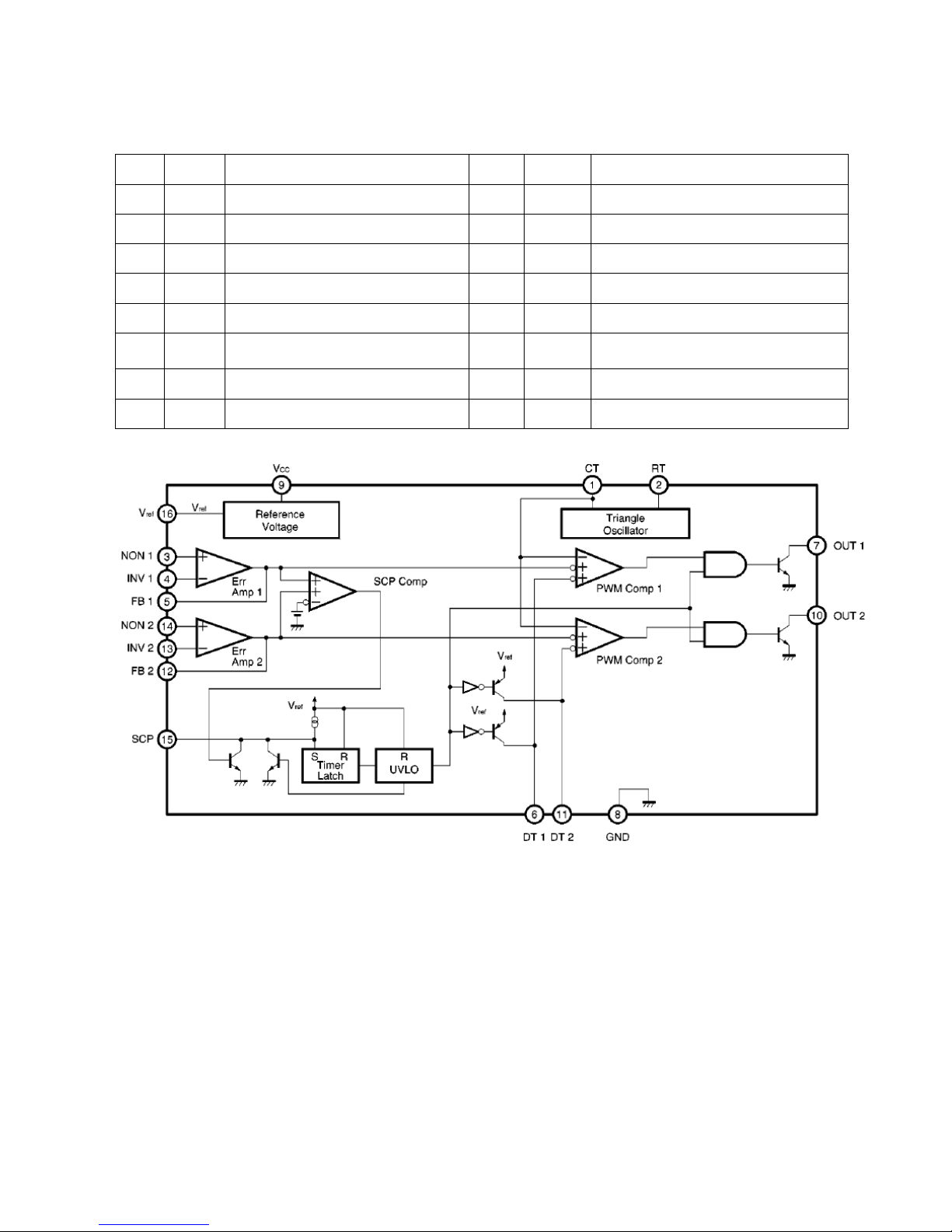
BA9741F: PWM control, voltage range for working: 3.6~35V, Has such functions as short-voltage
protection, Over-voltage protection, over-current protection and etc. The function of each pin and the circuit
diagram inside are as follows:
PIN NAME FUNCTION PIN NAME FUNCTION
1 CT External timing capacitor 9 VCC Power supply
2 RT External timing resistor 10 2OUT Output 2
3 1IN+ Positive input for error amplifier 1 11 2DTC Output 2 dead time/soft start setting
4 1IN- Positive input for error amplifier 2 12 2FBK Error amplifier 2 output
5 1FBK Error amplifier 1 output 13 2IN+ Positive input for error amplifier
6 1DTC
Output 1 dead time/soft start
setting
14 2IN- Positive input for error amplifier
7 1OUT Output 1 15 SCP Timing latch setting
8 GND Ground 16 REF Reference voltage output (2.5v)
BUFFALO Service Manual
15
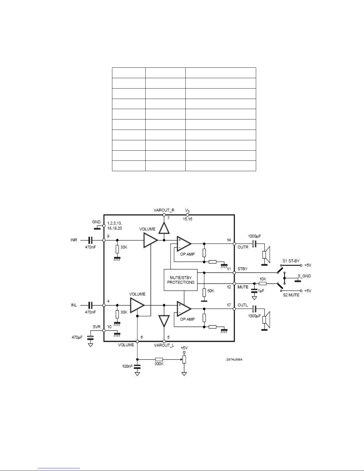
TDA7496: It is a stereo 2W+2W class AB power amplifier assembled, specially designed for high quality sound,
TV and Monitor applications. It include linear volume control, Stand-by and mute functions, the function of each pin
and the circuit diagram inside are as follows:
NO. Symbol Description
15/16 VS Supply Voltage
4 INL Sound Input (left)
9 INR Sound Input (right)
14 OUTR Sound Output (right)
17 OUTL Sound Output (left)
6 VOLUME Volume adjust
11 STBY Saving Control
12 MUTE Sound Mute Control
10 SVR Supply Voltage Rejection
BUFFALO Service Manual
16
7.Trouble Shooting
7.1 Main board
No power
No power
Press power key and look
if the picture is normal
OK
Please reinsert and make sure
the AC of 100-240 is normal
Measure U201 PIN2=2.5V
U202 PIN2=3.3V
Reinsert or check
the power section
X401 and X601 oscillate
waveforms are normal
Check Correspondent
component.
Replace U401
Replace U601
Check Correspondent
component.
OK
OK
OK
OK
NG
NG
NG
NG
NG
BUFFALO Service Manual
17
No picture (LED orange)
No picture
The button if under
control
X601 oscillate
waveform is normal
Replace U601
Check
Correspondent
component.
Measure U202 PIN2=3.3V
U201 PIN2=2.5V
Check Correspondent
component
Replace U401
X401 oscillate
waveform is normal
Check Correspondent
component
OK
OK
OK
OK
NG
NG
NG
NG
NG

BUFFALO Service Manual
18
White screen
White screen
Measure Q204
base is high level?
Measure U202 PIN2=3.3V
U201 PIN2=2.5V
X401 oscillate
waveform is normal
Check Q203 is broken
or CN503 solder?
Check Correspondent
component
Replace PANEL
Check Correspondent
component
Replace U401
OK
OK
OK
Check Correspondent
component
OK
NG
NG
NG
NG
 Loading...