

Buffalo BU1715 Service Manual
Buffalo BU1715
SERVICE MANUAL
17” LCD Monitor
BU1715
THESE DOCUMENTS ARE FOR REPAIR SERVICE INFORMATION ONLY.EVERY REASONABLE
EFFORT HAS BEEN MADE TO ENSURE THE ACCURACY OF THIS MANUAL; WE CANNOT GUARANTEE
THE ACCURACY OFTHIS INFORMATION AFTER THE DATE OF PUBLICATION AND DISCLAIMS
RELIABILITY FOR CHANGES, ERRORS OR OMISSIONS.

Buffalo BU1715
2
Table of Contents
Table of Contents ------------------------------------------------------------------------------------------------------------------ 02
Revision List ---------------------------------------------------------------------------------------------------------------------03
1. Monitor Specification -------------------------------------------------------------------------------------------------------------04
2. LCD Monitor Description -----------------------------------------------------------------------------------------------------05
3. Operation Instructions -----------------------------------------------------------------------------------------------------06
3.1 General Instructions --------------------------------------------------------------------------------------------------06
3.2 Control Button -----------------------------------------------------------------------------------------------------------06
3.3 Adjusting The Picture -------------------------------------------------------------------------------------------------------07
4. Input/Output Specification ----------------------------------------------------------------------------------------------------09
4.1 Input Signal Connector--------------------------------------------------------------------------------------------------------09
4.2 Factory Preset Display Modes ------------------------------------------------------------------------------------------10
4.3 Power Supply Requirements -----------------------------------------------------------------------------------------11
4.4 Panel Specification ----------------------------------------------------------------------------------------------------12
5. Block Diagram ---------------------------------------------------------------------------------------------------------------------- 15
5.1 Monitor Exploded View -------------------------------------------------------------------------------------------------------15
5.2 Software Flow Chart ----------------------------------------------------------------------------------------------------------16
5.3 Electrical Block Diagram ----------------------------------------------------------------------------------------------------18
6. Schematic Diagram --------------------------------------------------------------------------------------------------------------21
6.1 Main Board ----------------------------------------------------------------------------------------------------------------------21
6.2 Power Board ---------------------------------------------------------------------------------------------------------------27
6.3 Audio Board ---------------------------------------------------------------------------------------------------------------------29
6.4 Key Pad Board -----------------------------------------------------------------------------------------------------------------30
7. PCB Layout ------------------------------------------------------------------------------------------------------------------------ 31
7.1 Main Board --------------------------------------------------------------------------------------------------------------------31
7.2 Power Board ---------------------------------------------------------------------------------------------------------------33
7.3 Audio Board ---------------------------------------------------------------------------------------------------------------36
7.4 Key Board ------------------------------------------------------------------------------------------------------------------------36
8. Maintainability ---------------------------------------------------------------------------------------------------------------------37
8.1 Equipments and Tools Requirements ------------------------------------------------------------------------------------37
8.2 Troubleshooting -------------------------------------------------------------------------------------------------------------- 38
9. White-Balance, Luminance Adjustment ------------------------------------------------------------------------------------43
10.EDID Content -----------------------------------------------------------------------------------------------------------------------45
11.BOM List ------------------------------------------------------------------------------------------------------------------------------46
T780KA4NJSMCA -----------------------------------------------------------------------------------------------------------46-58

Buffalo BU1715
3
Revision List
Revision Date Change Description
A00 Jul-18-05 Initial release
Buffalo BU1715
4
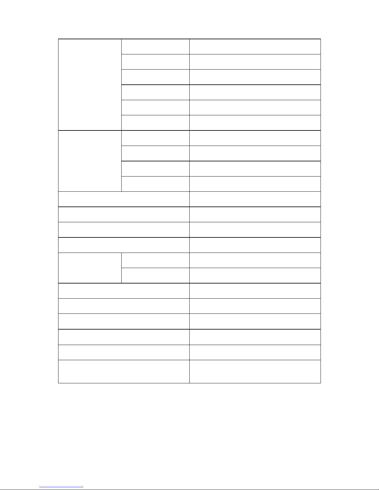
1. Monitor Specifications
Driving system TFT Color LCD
Panel M170EG01
Size 43.2 cm (17.0")
Pixel pitch 0.264mm(H) x 0.264mm(V)
Viewable angle 140° (H) 130° (V)
LCD Panel
Response time 16 ms (typ.)
Video R, G, B Analog Interface
Separate Sync. H/V TTL
H-Frequency 24kHz – 80kHz
Input
V-Frequency 55Hz-75Hz
Display Colors 16.2M Colors
Dot Clock 135MHz(max.)
Max. Resolution 1280 x 1024
Plug & Play VESA DDC2B
TM
ON Mode ≤39W
EPA ENERGY STAR®
OFF Mode ≤2W
Audio output Rated Power 1.2 W rms (Per channel)
Input Connector D-Sub 15pin
Input Video Signal
Analog:0. 7Vp-p(standard)
75 OHM, Positive
Maximum Screen Size
Horizontal : 337.920mm
Vertical: 270.336mm
Power Source 100~240VAC,50~60Hz
Environmental
Operating Temp: 0° to 35°C
Storage Temp.: -20° to 60°C
Operating Humidity: 15% to 90%
Buffalo BU1715
5
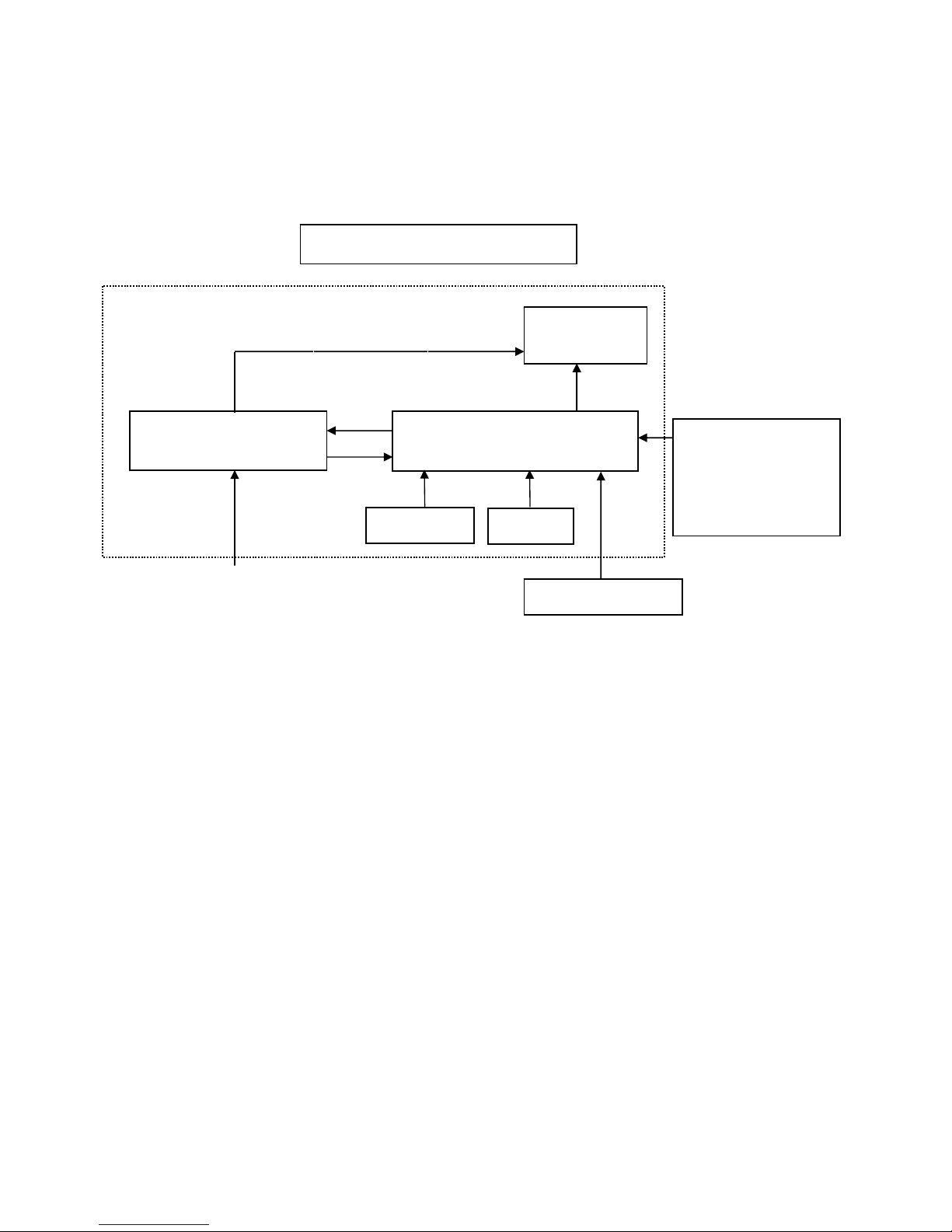
2. LCD Monitor Description
The LCD MONITOR will contain a main board, an inverter/power board, an audio board and a keypad board
which house the flat panel control logic, brightness control logic and DDC.
The power board will provide AC to DC Inverter voltage to drive the backlight of panel and the main board chips
each voltage.
Monitor Block Diagram
Video signal, DDC
Power board
(
Include: adapter, inverter)
Flat Panel and
CCFL backlight
Main Board
Keyboard
RS232 Connector
For white balance
adjustment in factory
mode
HOST Computer
CCFL Drive.
AC-IN
100V-240V
Audio Board
Buffalo BU1715
6
3. Operating Instructions
3.1 General Instructions
Press the power button to turn the monitor on or off. The other control buttons are located at front panel of the
monitor. By changing these settings, the picture can be adjusted to your personal preferences.
-
The power cord should be connected.
-
Connect the video cable from the monitor to the video card.
-Press the power button to turn on the monitor, the power indicator will light up.
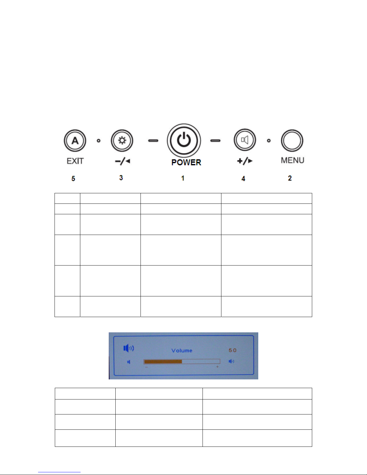
3.2 Operating Instructions
NO. Item Within OSD Without OSD
1 Power Button Turn on/off Turn on/off
2 MENU Button
1.Enter the OSD sub menu
2.Select the OSD menu
Open OSD menu
3 Left Arrow/- Button
1.Move the cursor to left
2.Adjust down when menu
item selected
Open Bright menu
4 Right Arrow/+ Button
1.Move the cursor to left
2.Adjust down when menu
item selected
Open the Volume menu
5 Exit Button
1.Exit Sub menu
2. Exit the menu item
Run the Auto Adjust when this
button keep to push for 1 second
Hot keys
Button Function Remark
Left Arrow/- Button
To change the ECO mode and
MAX mode and User mode
The item adjust the power consumption
to change the luminance
Right Arrow/+ Button To Adjust the Volume
When Mute function is ON, if they change
the volume then mute function is off
Exit Button To run the Auto Adjust
When this button keep to push for 1
seconds
Buffalo BU1715
7
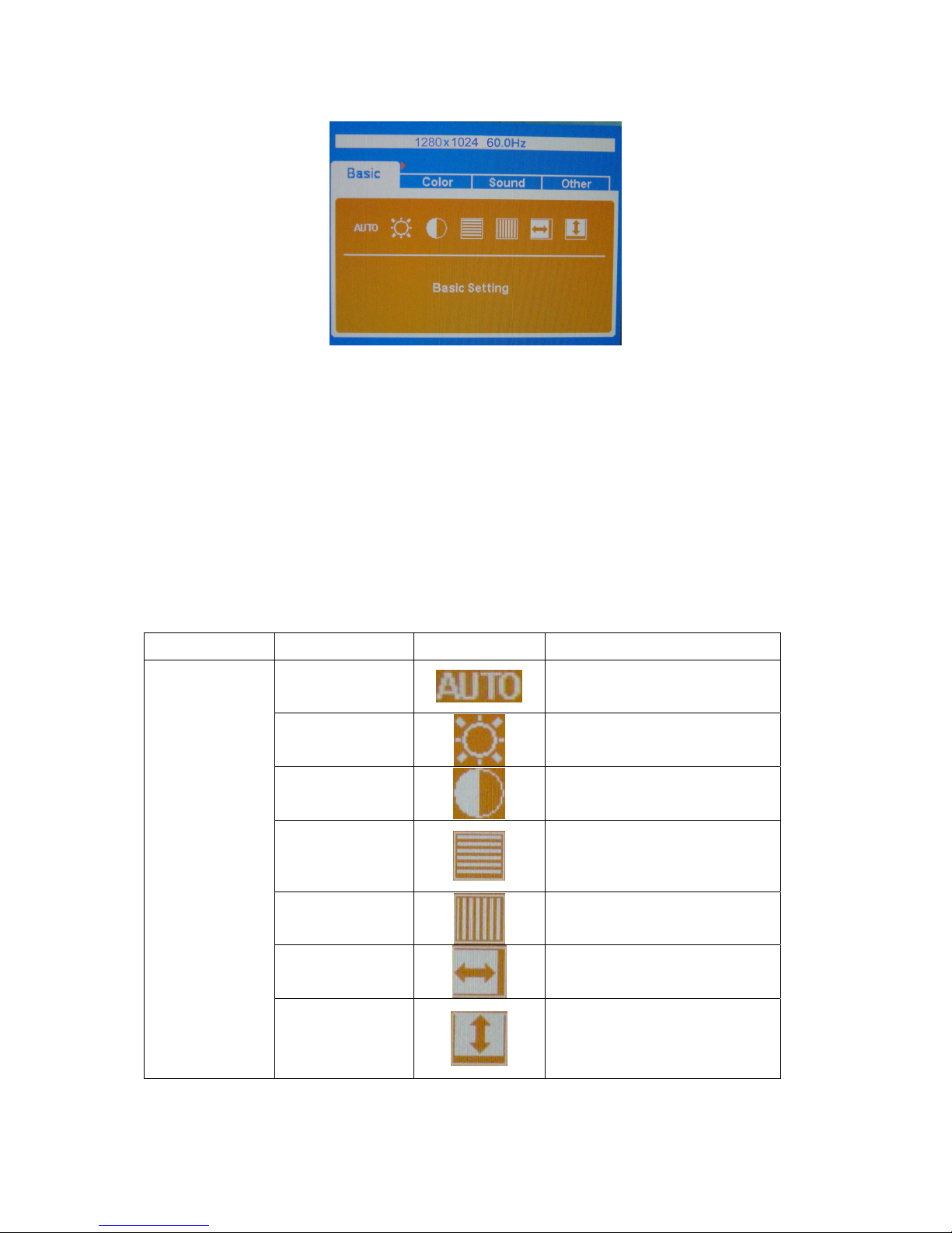
3.3 Adjusting the Picture
Steps:
1. Press MENU button to display OSD main menu, Press Left button or Right button may select other main Menu.
2. Press MENU button to adjust items of each main menu.
3. Press Left button or Right button may select item you wish to enter.
4. Press MENU button to enter, and press Left button or Right button to adjust item you select.
5. Press EXIT button may back previous menu.
6. Repeat steps 2-5 to adjust an additional item, or select the EXIT button to return to previous menu.
The description for control function:
Main Menu Item Sub Menu Item Sub Menu Icon Description
Auto
Auto Adjust the H/V Position,
Phase and Clock of picture
Brightness
Backlight Adjustment
Contrast
Contrast from Digital-register
Phase
Adjust Picture Phase to reduce
Horizontal-Line noise
Clock
Adjust picture Clock to reduce
Vertical-Line noise
H. Position
Adjust the horizontal position of
the picture
Basic
V. Position
Adjust the vertical position of the
picture
Buffalo BU1715
8
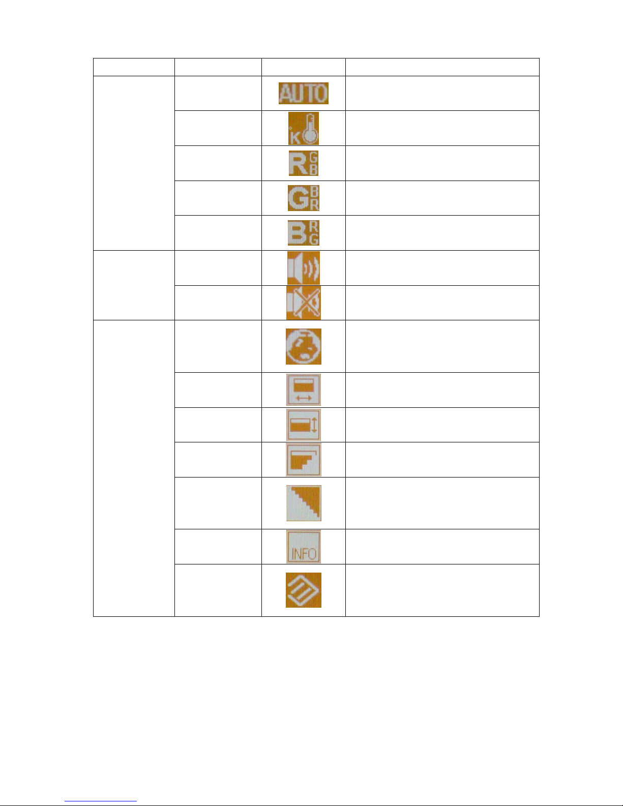
Main Menu Item Sub Menu Item Sub Menu Icon Description
Auto
Auto adjust color
Color Temp
Recall Color Temperature from EEPROM
Red Setting
Red Gain from Digital-register
Green Setting
Green Gain from Digital-register
Color
Blue Setting
Blue Gain from Digital-register
Volume
Audio adjustment
Sound
Mute
Audio prohibition
OSD language
OSD language selection
(English or Japanese)
OSD H-Position
Adjust the horizontal position of the OSD
OSD V-Position
Adjust the vertical position of the OSD
OSD
Transparency
OSD Transparency adjustment
Smoothing
Smoothing adjustment
Information
Show the resolution, H/V frequency and
input port of current input timing
Other
Reset
Recall factory mode
Buffalo BU1715
9
4. Input Specification
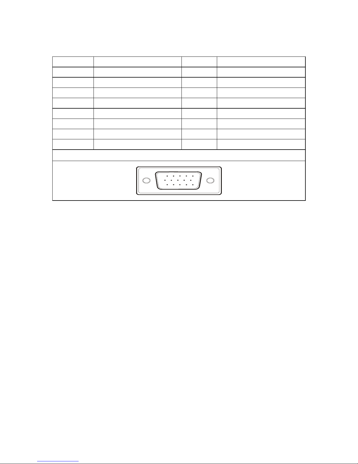
4.1 Input Signal Connector
PIN NO. Description PIN NO. Description
1. Red 9. +5V
2. Green 10. Detect Cable
3. Blue 11. NC
4. Ground 12. DDC-Serial Data
5. Ground 13. H-Sync
6. R-Ground 14. V-Sync
7. G-Ground 15. DDC-Serial Clock
8. B-Ground
VGA Connector Layout
15
6
10
11 15
Buffalo BU1715
10
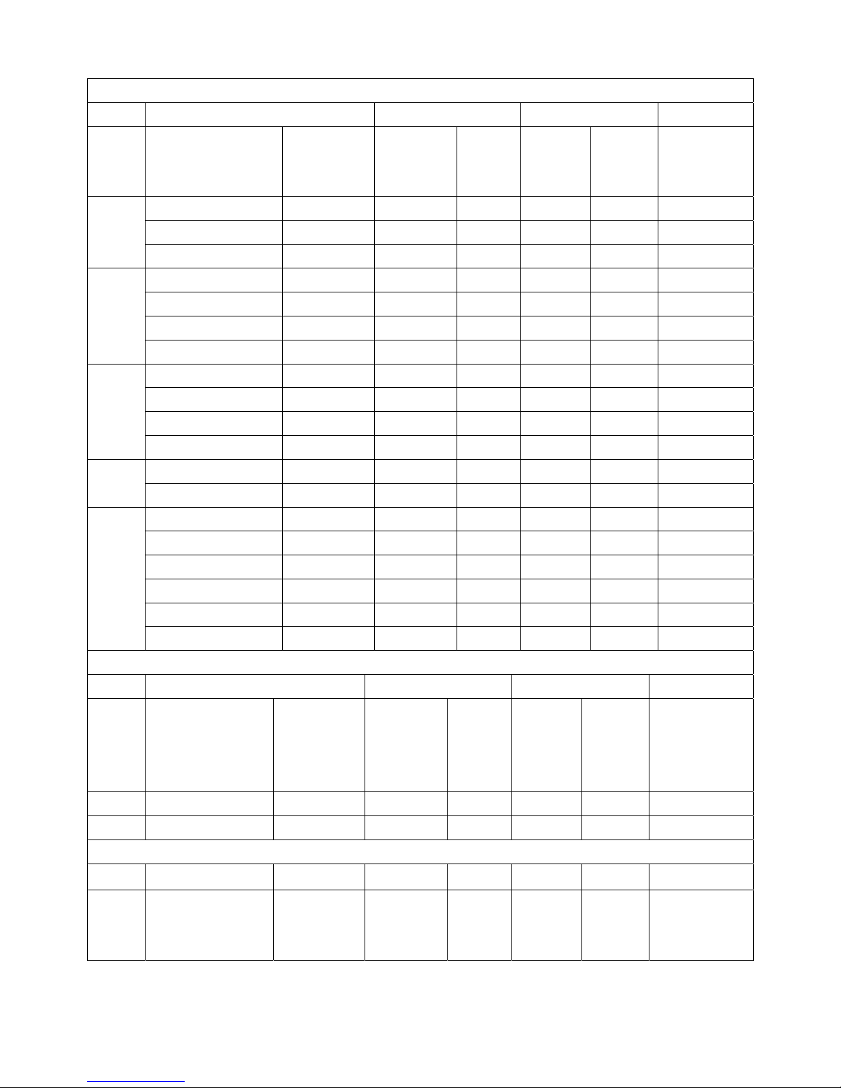
4.2 Factory Present Display Modes
VESA MODES
Horizontal Vertical
Mode Resolution Total
Nominal
Frequency
+/- 0.5kHz
Sync
Polarity
Nominal
Freq.
+/- 1 Hz
Sync
Polarity
Nominal
Pixel Clock
(MHz)
640x480@60Hz 800 x 525 31.469 N 59.940 N 25.175
640x480@72Hz 832 x 520 37.861 N 72.809 N 31.500
VGA
640x480@75Hz 840 x 500 37.500 N 75.00 N 31.500
800x600@56Hz 1024 x 625 35.156 N/P 56.250 N/P 36.000
800x600@60Hz 1056 x 628 37.879 P 60.317 P 40.000
800x600@72Hz 1040 x 666 48.077 P 72.188 P 50.000
SVGA
800x600@75Hz 1056x625 46.875 P 75.000 P 49.500
1024x768@60Hz 1344x806 48.363 N 60.004 N 65.000
1024x768@70Hz 1328x806 56.476 N 70.069 N 75.000
1024x768@75Hz 1312x800 60.023 P 75.029 P 78.750
XGA
1024x768@72Hz 1304x798 57.7 P 72 P 78.4
1024x768@75Hz 1326x804 60.2 P 75 P 80 MAC
1152x870@75Hz 1456x915 68.7 P 75 P 100
1152x864@75Hz 1600x900 67.5 P 75 P 108
1280x1024@60Hz 1688x1066 63.981 P 60.020 P 108.000
1280x1024@75Hz 1688x1066 79.976 P 75.025 P 135.000
1280x960@60Hz 1800x1000 60 P 60 P 108
1280x1024@70Hz 1720x1064 74.4 P 70 P 124.9
SXGA
1280x1024@72Hz 1724x1066 77.9 P 72 P 134.6
IBM MODES
Horizontal Vertical
Mode Resolution Total
Nominal
Frequency
+/- 0.5kHz
Sync
Polarity
Nominal
Freq.
+/- 1 Hz
Sync
Polarity
Nominal
Pixel
Clock
(MHz)
DOS* 720x400@70Hz 900 x 449 31.469 N 70.087 P 28.322
DOS 640x350@70Hz 800 x 449 31.469 P 70.087 N 25.175
MAC MODES
VGA 640x480@67Hz 864x525 35.000 N 66.667 N 30.240
SVGA 832x624@75Hz 1152x667 49.725 N 74.551 N 57.2832
Buffalo BU1715
11
4.3 Power Supply Requirement
NO. Parameter Description
1 A/C Line voltage range 100 V ~ 240 V
2 A/C Line frequency range
50 ± 3Hz, 60 ± 3Hz
3 Input Voltage transients
280 volts AC for 10 sec @40℃
4 Current 1.5A max at 100V; 0.8A max at 240 V
5 Peak surge current
< 60A peak at 240 VAC and cold starting
< 30A peak at 120VAC and cold starting
6 Leakage current < 3.5mA
7 Power line surge
No advance effects (no loss of information or defect)
With a maximum of 1 half-wave missing per second
Buffalo BU1715
12
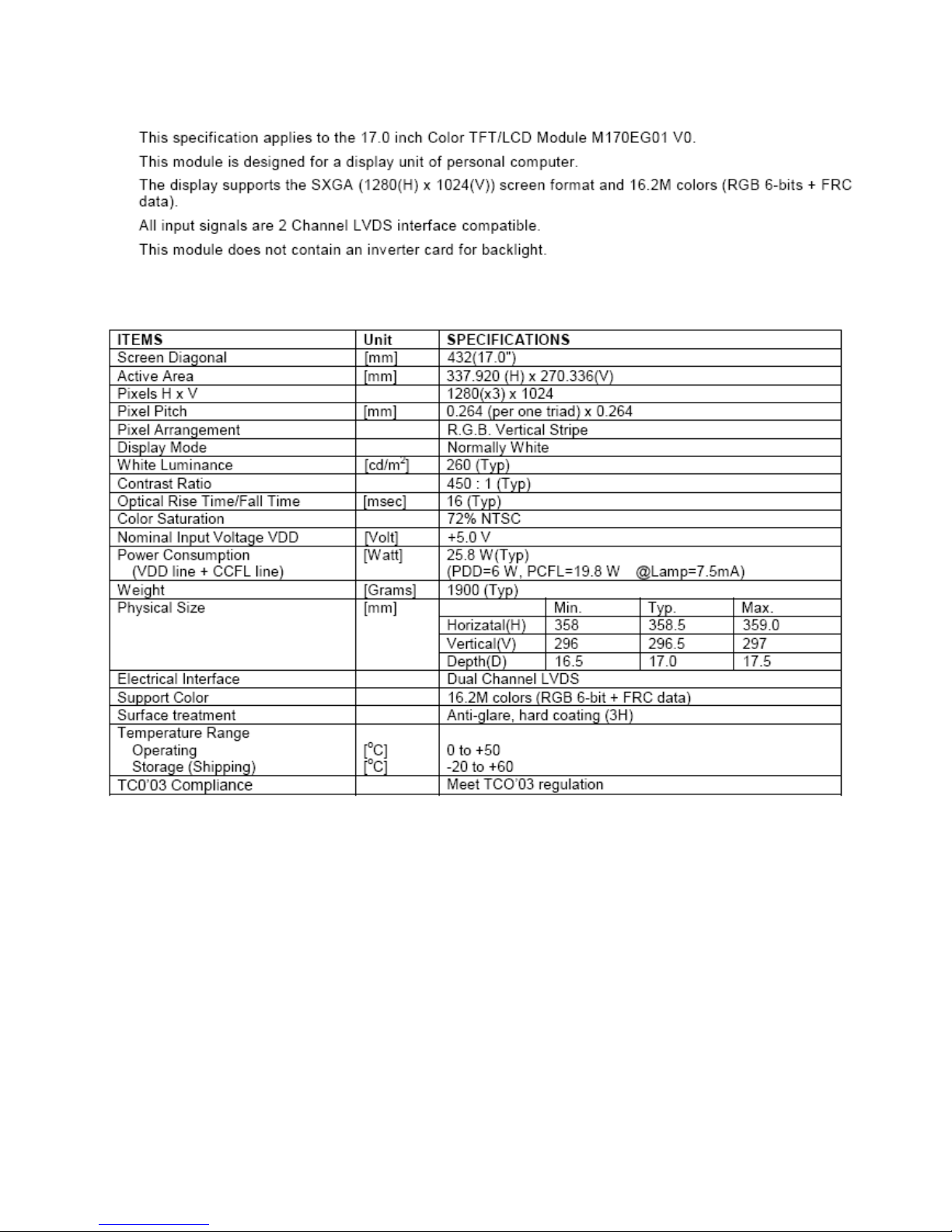
4.4 Panel Specification
4.4.1 Panel Feature
4.4.2 General Characteristics
Buffalo BU1715
13
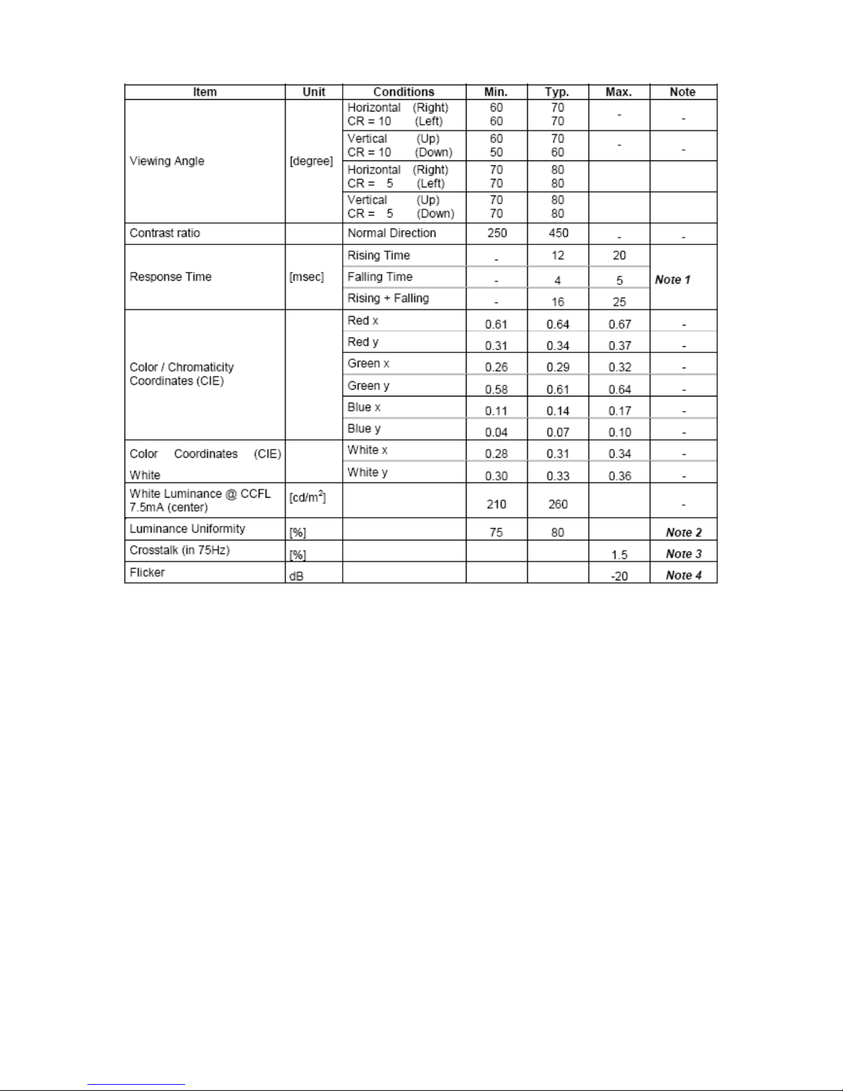
4.4.3 Optical Characteristics
Buffalo BU1715
14
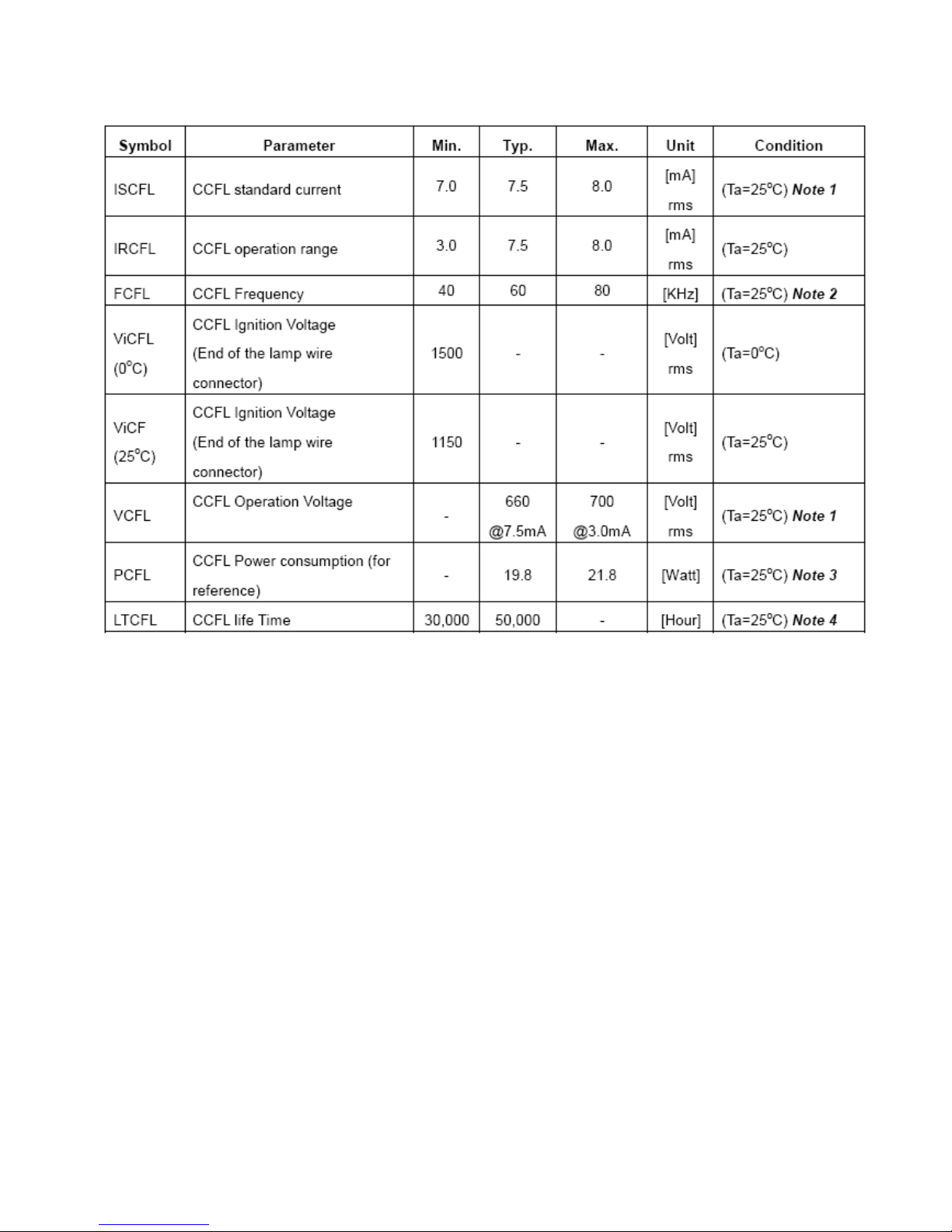
4.4.4 Parameter Guider Liner For CCFL Inverter
Backlight Unit:
Buffalo BU1715
15
5. Block Diagram
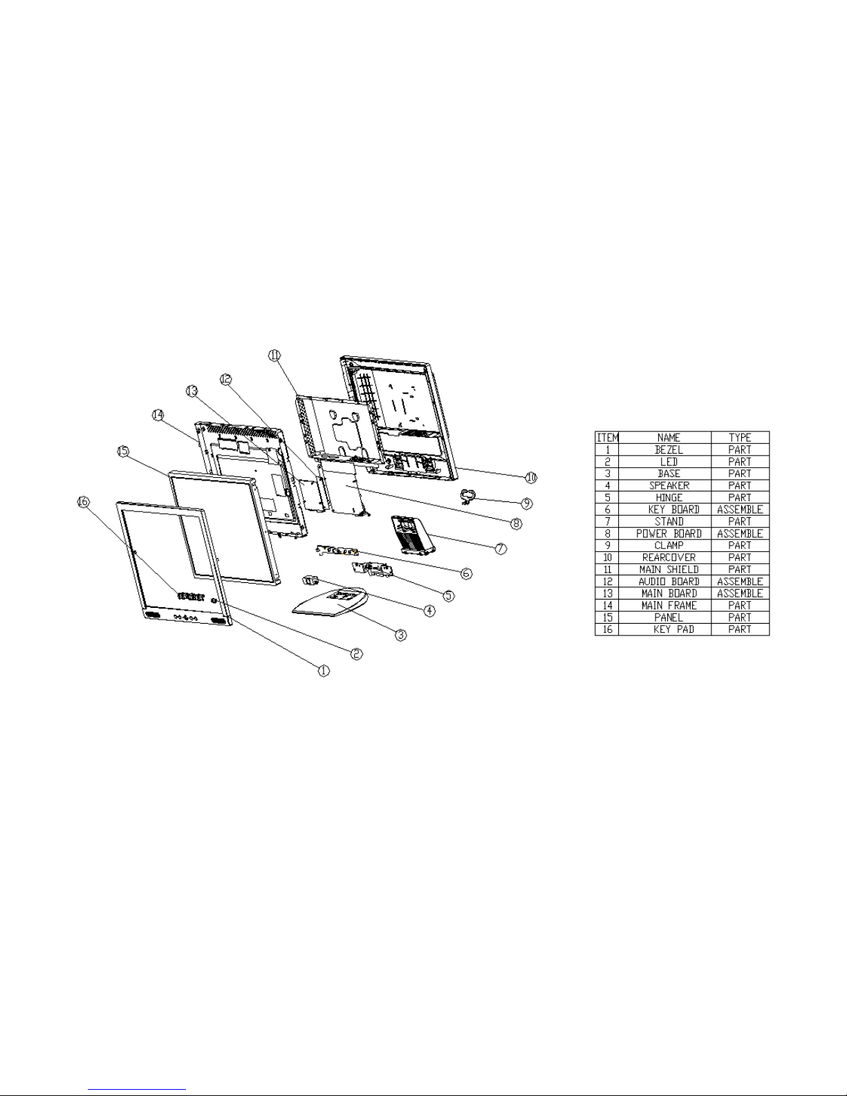
5.1 Monitor Exploded View
Buffalo BU1715
16
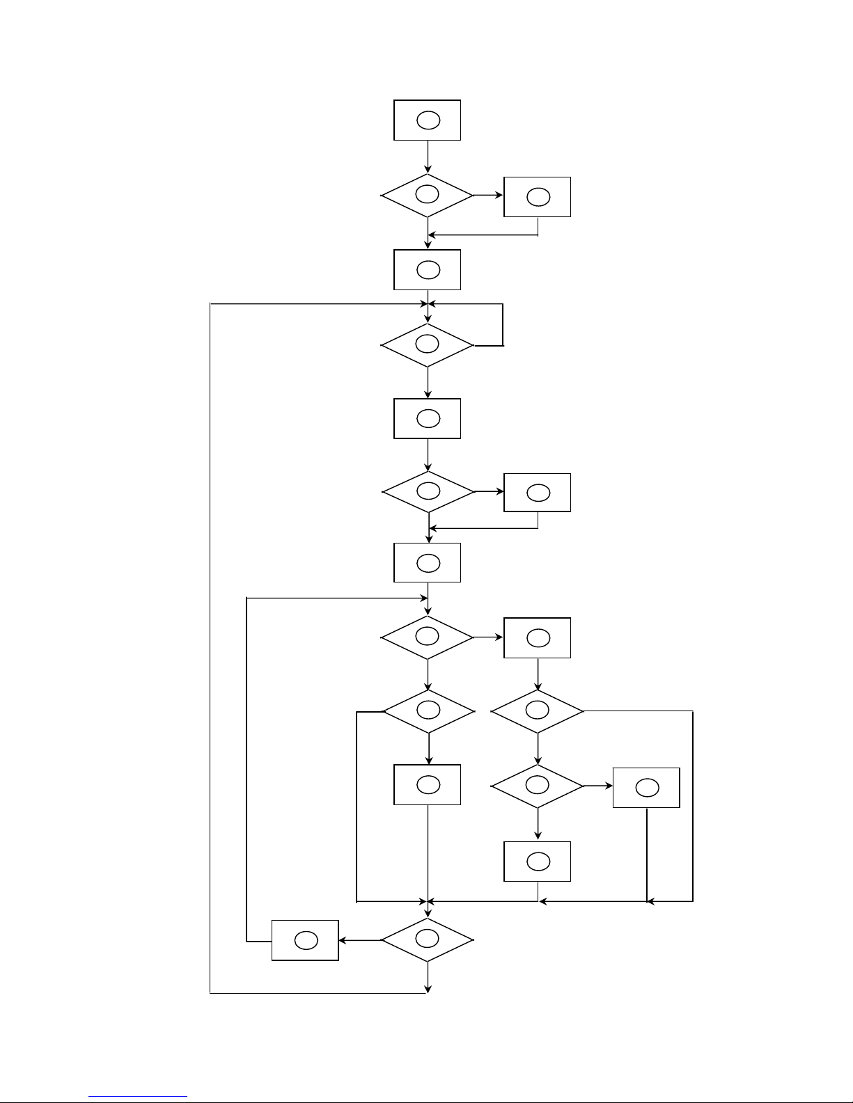
5.2 Software Flaw Chart
1
2
N
Y
5
Y
N
10
Y
N
12
Y
N
7
Y
N
6
4
3
8
9
14
11
13
Y
N
15
Y
N
16
17
19
Y
N
18

Buffalo BU1715
17
1) MCU initializes.
2) Is the EEPROM blank?
3) Program the EEPROM by default values.
4) Get the PWM value of brightness from EEPROM.
5) Is the power key pressed?
6) Clear all global flags.
7) Are the AUTO and SELECT keys pressed?
8) Enter factory mode.
9) Save the power key status into EEPROM.
Turn on the LED and set it to green color.
Scalar initializes.
10) In standby mode?
11) Update the lifetime of back light.
12) Check the analog port, are there any signals coming?
13) Does the scalar send out an interrupt request?
14) Wake up the scalar.
15) Are there any signals coming from analog port?
16) Display "No connection Check Signal Cable" message. And go into standby mode after the
message disappears.
17) Program the scalar to be able to show the coming mode.
18) Process the OSD display.
19) Read the keyboard. Is the power key pressed?
Buffalo BU1715
18
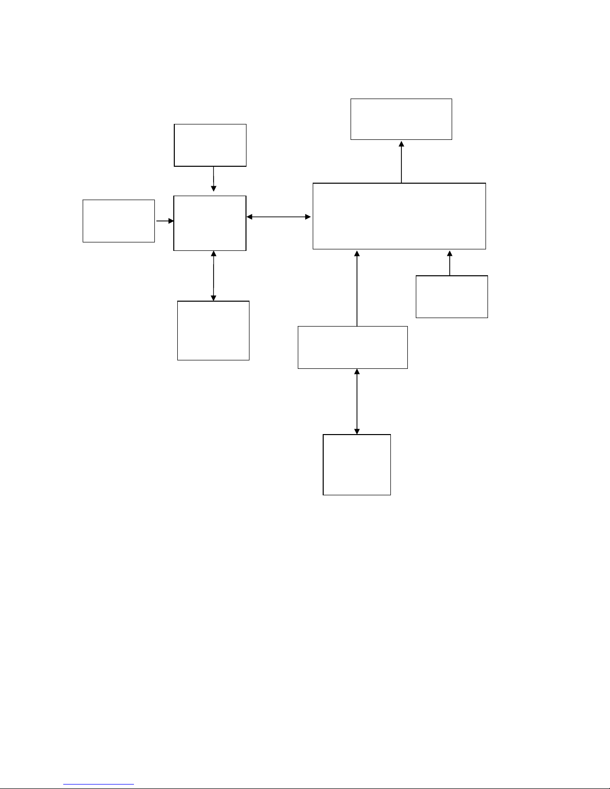
5.3 Electrical Block Diagram
5.3.1 Scaler Board Block Diagram
MCU
MTV512MV
(
U601
)
Scalar TSU16AK PQFP-128
(Include ADC, OSD)
(U401)
EEPROM
M24C16
(U602)
D-Sub Connector
(CN301)
EEPROM
M24C02
(U301)
H sync
V sync
RGB
DB15_SDA
DB15
_
SCL
EPR_SDA
EPR_SCL
LCD Interface
(CN503)
OSD Control
KEY PAD
20MHz
CRYSTAL
14.318MHz
CRYSTAL
 Loading...