

Page 1

Layer 2 10 Gigabit Switch
BS-XP20 Series
User Manual
Americas: www.buffaloamericas.com
Europe: www.buffalo-technology.com
35021193-02
2016.10
Page 2

1
Contents
Chapter 1 Initial Settings ...............................................4
Product Requirements .....................................................................4
Install Business Switch Configuration Tool ....................................4
Change Switch's IP Address .............................................................5
Open Settings ................................................................................ 11
Change Username and Password ................................................ 14
MAC Address Learning ................................................................. 15
Chapter 2 Settings ....................................................... 16
Menu .............................................................................................. 16
System Information ...................................................................... 17
System ............................................................................................ 17
System IP Settings ......................................................................... 18
VLAN .............................................................................................. 19
VLAN Settings ..........................................................................................19
VLAN Ports ...............................................................................................20
MAC Addresses .............................................................................. 21
Static MAC Filtering .................................................................................21
Port Settings .................................................................................. 22
Status ........................................................................................................22
Speed/Mode Settings .............................................................................. 23
System Security ............................................................................. 24
Administration Account ..........................................................................24
QoS ................................................................................................. 25
Page 3

2
QoS Settings ............................................................................................. 25
QoS Mapping ............................................................................................26
VoIP Auto Priority ....................................................................................27
Security .......................................................................................... 28
Auto DoS Attack Prevention ...................................................................28
Port Trunking ................................................................................. 29
Traffic Control ................................................................................ 30
Mirroring ........................................................................................ 31
IGMP ............................................................................................... 31
Status ........................................................................................................31
IGMP Settings ...........................................................................................32
IGMP Querier ............................................................................................ 32
IGMP Router Port .....................................................................................33
Loop Prevention ............................................................................ 33
Update Firmware ........................................................................... 34
Back Up and Restore ..................................................................... 35
Reboot ............................................................................................ 35
Initialize ......................................................................................... 36
Statistics ......................................................................................... 36
Network Diagnostics ..................................................................... 37
Cable Diagnostics .......................................................................... 38
Chapter 3 Troubleshooting ........................................ 39
LED Is Not Lit, Abnormal Lighting or Blinking ............................ 39
Cannot Access Settings ................................................................. 39
Forgot the Username or Password .............................................. 39
Page 4

3
Appendix A Specifications .......................................... 40
Product Specifications .................................................................. 40
Port Specifications ................................................................................... 40
Factory Default Settings ............................................................... 41
Appendix B Regulatory Compliance Information ..... 43
For Customers in the United States ............................................. 43
For Customers in Europe .............................................................. 44
Page 5

4
Chapter 1 Initial Settings
Product Requirements
Compatible Devices and Browsers
Compatible Devices to Connect to BS-XP
10GBASE-T/1000BASE-T/100BASE-TX compatible devices (PCs, Mac, NAS, switches)
Compatible Browsers to Enter Settings
Microsoft Edge
Internet Explorer 8/9/10/11
Mozilla Firefox
Google Chrome
Refer to our website to check the latest information on compatible browser versions.
Install Business Switch Configuration Tool
Install "Business Switch Configuration Tool" before you perform the following procedure. (Compatible with Windows
only.)
Note: You can download the latest version of Business Switch Configuration Tool from the URLs below:
BS-XP2008 http://d.buffalo.jp/bs-xp2008/
BS-XP2012 http://d.buffalo.jp/bs-xp2012/
Page 6
5
Change Switch's IP Address
To enter Settings, the switch's web user interface, the switch's IP address should belong to the same segment as
your PC's IP address.
1 Connect the switch to your PC and your network with an Ethernet cable (sold separately). Confirm that link/act
LED of the connected port is on.
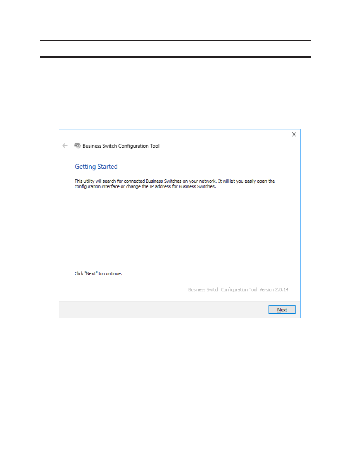
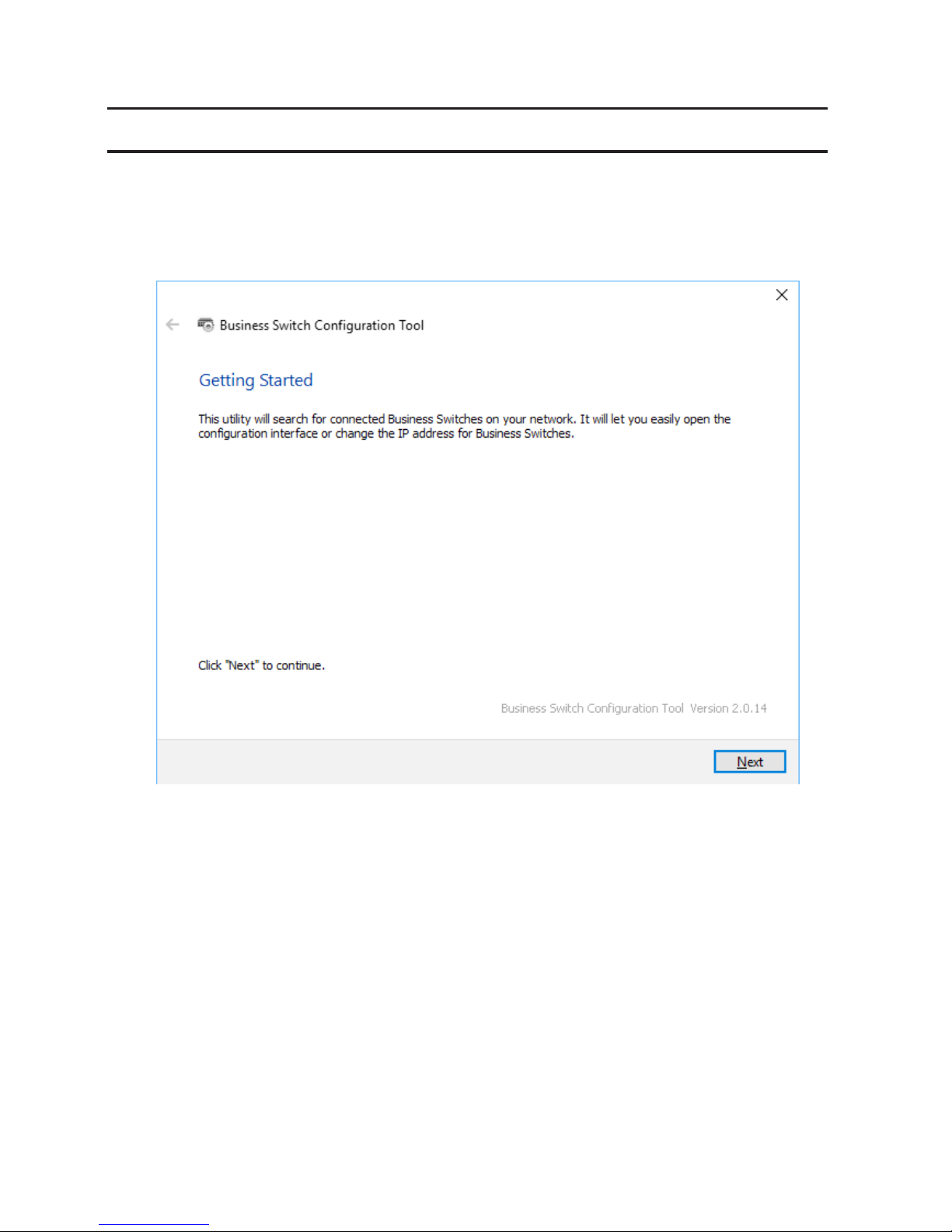
2 Double-click the "Business Switch Configuration Tool" icon to open Business Switch Configuration Tool.
3 Click Next to start searching for the switch.
Page 7
6
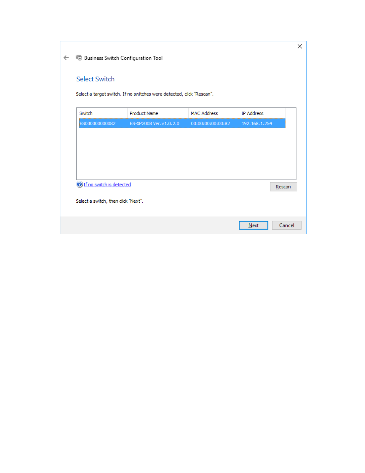
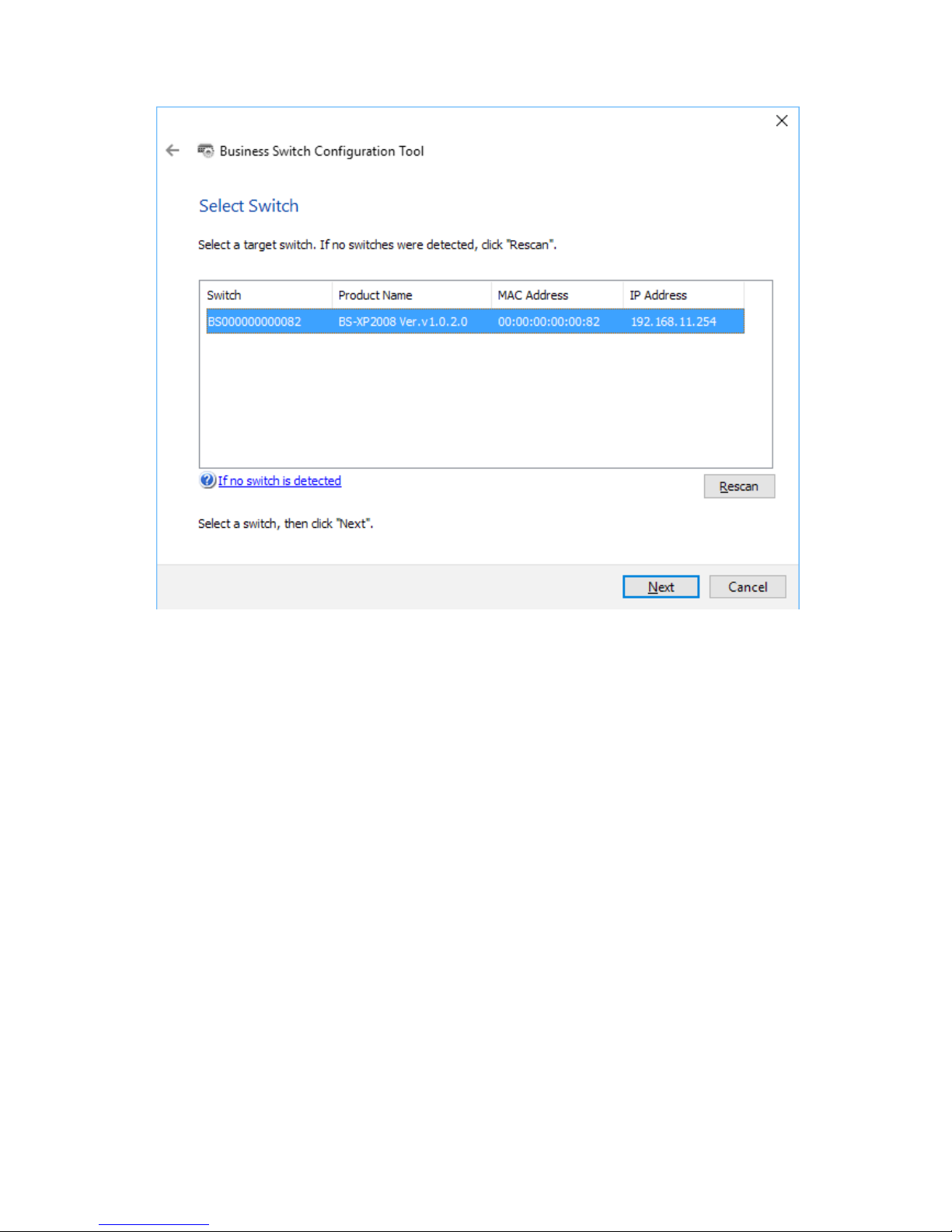
4 Select the switch and click Next.
Page 8
7
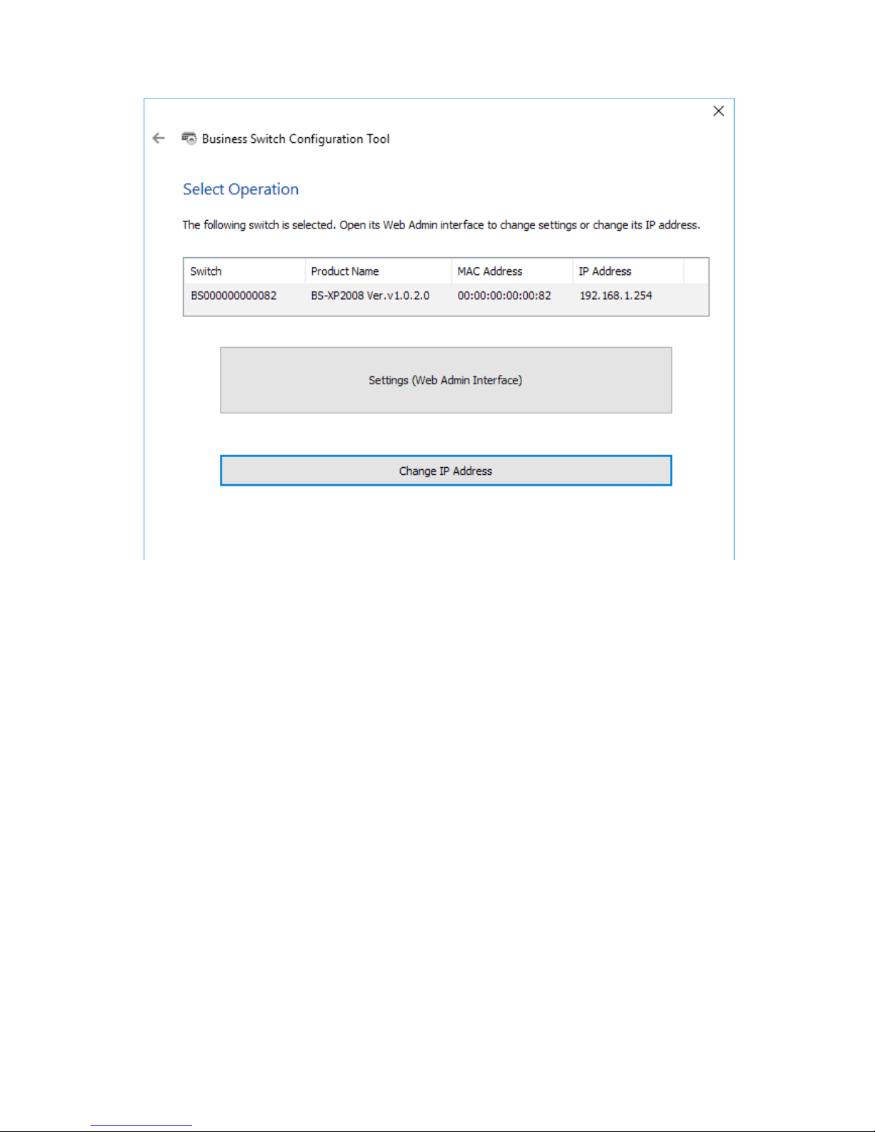
5 Click Change IP Address.
Page 9
8
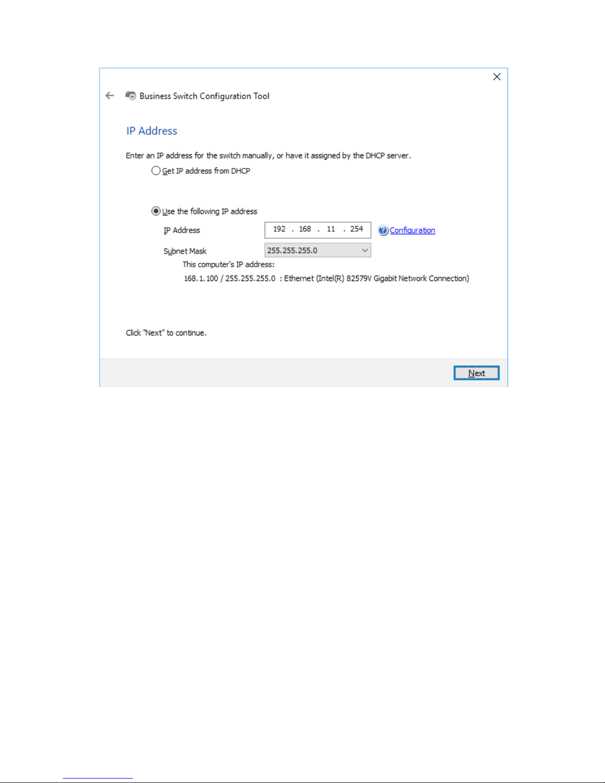
6 Configure the switch's IP address to match the segment of the IP address of your PC and click Next.
Page 10
9
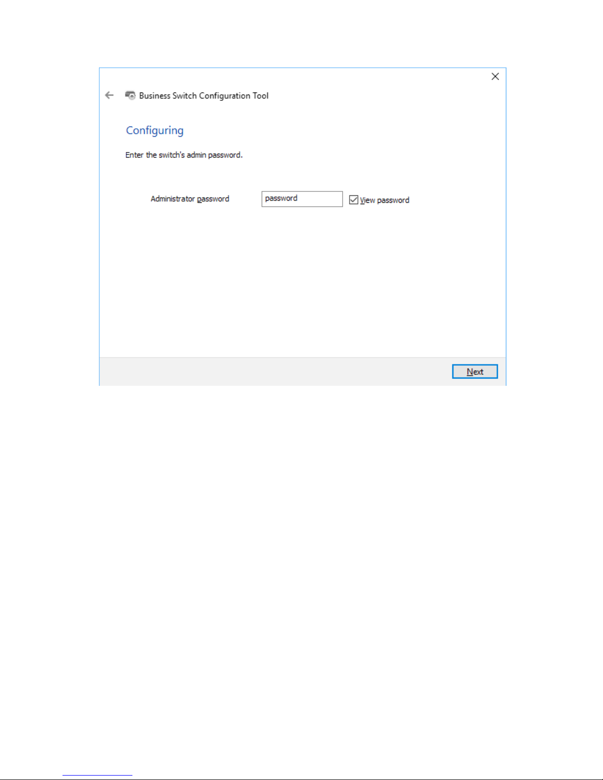
7 If the password input screen is displayed, enter "password" and click Next.
Page 11
10
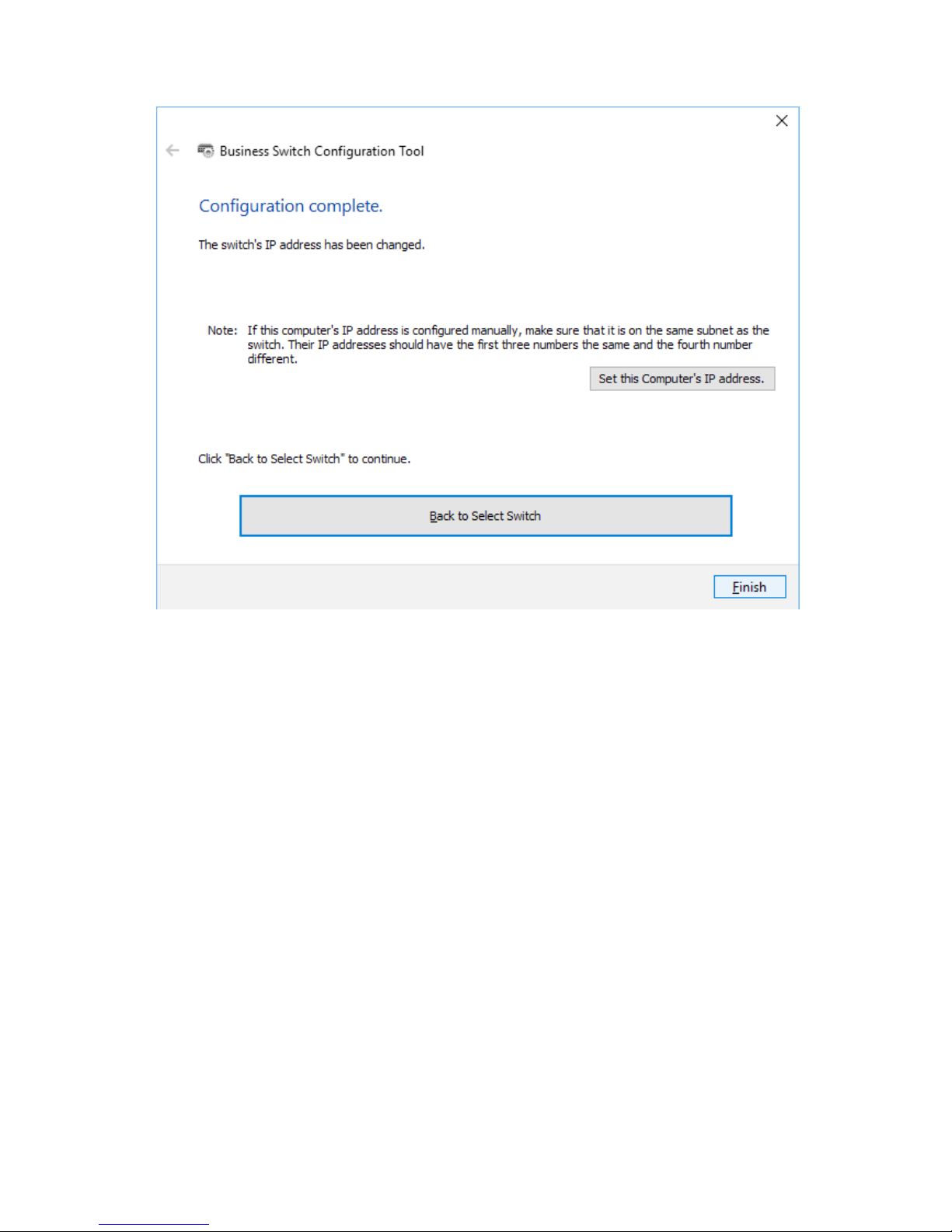
8 Click Finish.
Page 12
11
Open Settings
1 Configure the switch's IP address, referring to the "Change Switch's IP Address" section above.
2 Double-click the "Business Switch Configuration Tool" icon to open Business Switch Configuration Tool.
3 Click Next to start searching for the switch.
Page 13
12
4 Select the switch and click Next.
Page 14
13
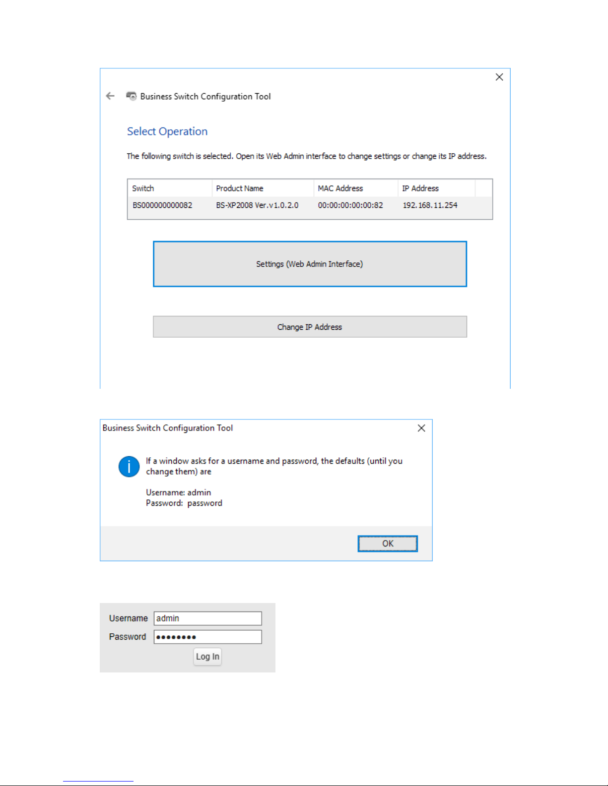
5 Click Settings (Web Admin Interface).
6 Click OK.
7 A web browser is launched and the login screen is displayed. Enter "admin" as the username and "password" as
the password, then click Log In.
Note: There is a message window, "The switch's configuration interface is now open in a browser window."
under the browser window. Click Complete to close the window.
Page 15
14
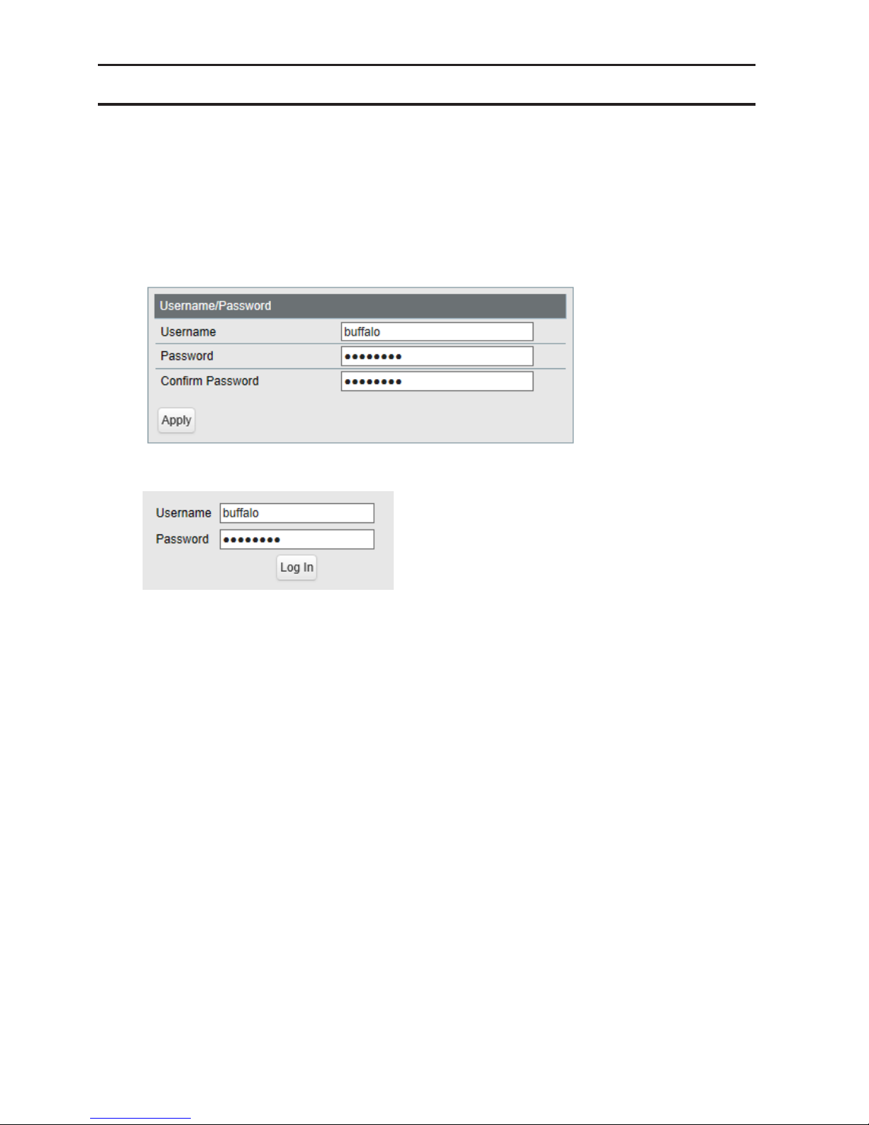
Change Username and Password
To change the default username and password from "admin" and "password", refer to the following procedure.
1 Open Settings.
2 Navigate to Basic - System Security - Administration Account.
3 Enter your new username and password (also fill the "Confirm Password" field), then click Apply.
Note: You may enter up to 8 alphanumeric characters, hyphens (-), and underscores (_) for the new username
and password.
4 Enter the new username and password, then click Log In.
Page 16

15
MAC Address Learning
This switch uses SVL (Shared VLAN Learning) to learn MAC addresses. SVL is a method that retains a shared MAC
address table for the entire switch. It differs from IVL, which retains a MAC address table for each VLAN. Be sure you
understand how SVL works before you create a VLAN with the switch.
Differences between Operation of SVL and IVL
Switch 1
Switch 2
VLAN 1 VLAN 2
VLAN 1VLAN 2
VLAN 3
PC 1
(VLAN 1, PVID 1)
PC 2
(VLAN 2, PVID 2)
PC 3
(VLAN 1, 2, 3 PVID 3)
SVL
When PC 1 and PC 3 communicate, PC 3 is learned by port 1 on switch 2 so PC 2 and PC 3 cannot communicate.
IVL
When PC 1 and PC 3 communicate, PC 3 is learned by both VLAN 1 and VLAN 2 so PC 2 and PC 3 can communicate.
However, frames sent from PC 3 to PC 1 are also delivered to PC 2.
Page 17

16
Chapter 2 Settings
Refer to the "Open Settings" section in chapter 1 to access Settings.
Menu
System Information Displays the switch's information.
Basic
System Configure the switch's name, location, and contact.
System IP Settings
Configure the switch's IPv4 address, subnet mask, and
default gateway.
VLAN
VLAN Settings
Confirm VLAN status and create new VLAN. This switch's IP
address can also be configured on this page.
VLAN Ports Configure PVID (Port VLAN ID).
MAC Addresses Static MAC Filtering Configure static MAC address-based filtering.
Port Settings
Status Displays port status.
Speed/Mode Settings Configure transmission rate and flow control for each port.
System Security
Administration
Account
Configure administration username and password.
Advanced
QoS
QoS Settings Configure QoS priority.
QoS Mapping Configure QoS mapping for each priority.
VoIP Auto Priority Configure priority for SIP, H.323, SCCP.
Security
Auto DoS Attack
Prevention
Configure to drop specified packets.
Port Trunking Configure port trunking.
Traffic Control Configure traffic storm control.
Mirroring Configure to monitoring traffic.
IGMP
Status Displays IGMP status.
IGMP Settings Configure IGMP snooping.
IGMP Querier Configure IGMP querier.
IGMP Router Port Specify ports to connect to multicast routers.
Loop Prevention Configure loop prevention settings.
Management
Update Firmware Update firmware from a local file.
Back Up and Restore Save settings to a file or restore settings from a file.
Reboot Reboot the switch.
Initialize Initialize the switch.
Statistics Displays the switch's statistics.
Network Diagnostics Execute communication test to the specified IP address.
Cable Diagnostics
Confirm abnormalities of each Ethernet cable connected
to the switch.
Page 18

17
System Information
Displays the switch's information.
System Information Displays system information such as the switch name, and MAC address.
IPv4 Address
Displays information such as the switch's IPv4 address, subnet mask, and default
gateway.
Version Displays the switch's firmware, boot code, and hardware versions.
System
Configure the switch's name, location, and contact.
Switch Name
Enter the switch's name. You may enter up to 50 alphanumeric characters,
hyphens, and underscores.
Location
Enter the location of the switch. You may enter up to 50 alphanumeric characters,
hyphens, underscores, and spaces.
Contact
Enter the contact information of the switch. You may enter up to 50 alphanumeric
characters, hyphens, underscores, and spaces.
Page 19

18
System IP Settings
Configure the switch's IP address, subnet mask, and default gateway.
Method of Acquiring IPv4
Address
Select a method of obtaining the switch's IP address.
Obtain from DHCP Server
Obtain the switch's IP address from DHCP server.
Static IP Address
Enter the IP address manually.
IPv4 Address
Enter the switch's IPv4 address if you select Static IP Address as the connection
method.
Subnet Mask
Enter the switch's subnet mask if you select Static IP Address as the connection
method.
Default Gateway
Enter the switch's default gateway if you select Static IP Address as the connection
method.
Page 20

19
VLAN
VLAN Settings
Confirm VLAN status and configure new VLAN.
Mode
Select a VLAN mode from "VLAN Settings" or "Privacy Separator". Privacy separator
is a mode that enables communication to the router from a port but blocks
communication between ports.
Note: VLAN and privacy separator cannot be used at the same time.
VLAN Status
Displays current VLAN and PVID (Port VLAN ID) status. Click Edit to edit the VLAN
selected. Click Delete to delete the VLAN selected. VLAN 1 cannot be deleted.
VLAN ID Specify VLAN ID from 2-4094.
VLAN Name
Enter the VLAN name. You may enter up to 17 alphanumeric characters, hyphens,
and underscores.
Page 21

20
Management VLAN
Check it if the VLAN is a management VLAN. Only devices which belong to the
management VLAN can open Settings.
Tagged Select when you assign the port to tag member.
Untagged Select when you assign the port to untag member.
Not Member Select when you do not assign the port to any member.
Reset Click to reset the changes to the previous settings.
Uplink
Appears when "Privacy Separator" is selected.
A router should be connected to the uplink port to connect to the Internet. Uplink
ports can communicate with all downlink ports. Specify at least 1 port to an uplink
port.
Downlink
Appears when "Privacy Separator" is selected.
Downlink ports are the ones which each device connected to. Downlink ports can
communicate with uplink ports, but cannot communicate with each downlink
port.
Note: In privacy separator mode, only the device connected to an uplink port can open Settings. If you
configure the port that your PC is connected as a downlink port, you cannot open Settings any more.
VLAN Ports
Configure PVID (Port VLAN ID).
PVID
Specify the port VLAN ID. The received untagged frames will be recognized as the
specified VLAN ID. (1-4094)
Acceptable Frame Type
Admit All
Receive both untagged and tagged frames.
Tagged Only
Receive tagged frames only and drop untagged frames.
Page 22

21
Ingress Filter
Enable
Drop frames if the received frame's VLAN ID is not a member of incoming port's
VLAN.
Disable
All tagged and untagged frames will be received.
Protected Port "Protected Port" enabled ports cannot communicate with each other.
MAC Addresses
Static MAC Filtering
Configure the filtering of MAC addresses that are registered manually. Only the frames with registered MAC address
as a source MAC address can pass through the ports that the MAC address is registered to.
Static MAC Filtering Check "Enable" to enable static MAC filtering.
MAC Address
Enter the MAC address you want to filter. (Example: 00:11:22:aa:bb:cc)
Up to 8 addresses can be registered per port.
Port Number Select a port to apply the static MAC filter.
Static MAC Filtering Table Displays the registered MAC addresses and port numbers.
Note: This function is not compatible with multicast MAC addresses, VRRP MAC addresses (00:00:5E:00:01:XX),
and broadcast MAC addresses.
Page 23

22
Port Settings
Status
Displays the port status.
Name Displays the port name.
Admin Displays whether the port is enabled (on) or disabled (off).
Link Status Displays whether the link is up or down.
Autonegotiation Displays whether the autonegotiation is enabled (on) or disabled (off).
Speed/Duplex Displays the speed and duplex status.
Flow Control Displays whether the flow control is enabled (on) or disabled (off).
IEEE 802.3az Displays whether IEEE 802.3az is enabled (on) or disabled (off).
APD Displays whether APD is enabled (on) or disabled (off).
Jumbo Frame
Displays whether jumbo frame is enabled (on) or disabled (off).
Note: Jumbo frames of up to 9216 frames (including header 14 bytes + FCS 4
bytes) can be forwarded.
Page 24

23
Speed/Mode Settings
Configure ports settings such as the transmission rate or flow control.
Name
Enter the port name. You may enter up to 15 alphanumeric characters, hyphens,
underscores, and spaces.
Admin Check to enable the port.
Mode Select the transmission rate and duplex.
Flow Control Check to enable flow control.
IEEE 802.3az Check to enable IEEE802.3az.
APD
Check to enable APD (auto power down). If enabled, power consumption of link
down ports can be reduced.
Jumbo Frame Check to enable jumbo frame settings.
Speed/Duplex Displays the current transmission rate and duplex.
Page 25

24
System Security
Administration Account
Configure the username and password.
Username
Enter the new username. You may enter up to 8 alphanumeric characters,
hyphens, and underscores.
Password
Enter the new password. You may enter up to 8 alphanumeric characters, hyphens,
and underscores.
Confirm Password Enter the new password again.
Page 26

25
QoS
QoS Settings
Configure the priority.
QoS Check to enable QoS. Click Show Detail to enable/disable QoS for each port.
Schedule Method
Configure the queue scheduling type.
Strict
Execute the queue scheduling based on strict priority. High-prioritized queues
are always forwarded strictly; low-prioritized queue will never be forwarded if any
data remains in the high-prioritized queue.
WRR
Execute the queue scheduling based on WRR (Weighted Round Robin). This will
forward queues in order of a round robin; even lower priority queues will be
forwarded at a constant rate. The priority can be specified from 0 (lowest) to 7
(highest).
Note: Packets without VLAN tag will belong to the lowest priority queue.
Page 27

26
Priority Type Select a priority parameter from DSCP, CoS, and IP precedence.
QoS Mapping
Configure port-based priority for DSCP, CoS, and IP precedence.
Port Priority Configure the priority of each port.
DSCP Mapping Configure the DSCP priority value from 0-63.
CoS Mapping Configure the CoS priority value from 0-7.
IP Precedence Mapping Configure the IP precedence priority value from 0-7.
Priority Configure the priority from 0-7.
Note: DSCP mapping, CoS mapping, and IP precedence mapping is displayed when each type is selected.
Page 28

27
VoIP Auto Priority
Configure the priority of SIP, H.323, SCCP.
VoIP Auto Priority
Check to enable VoIP auto priority. Click Show Detail to enable or disable this
functionality for each port.
CoS
Applied to the VoIP packets of SIP, H.323, SCCP only. If QoS is enabled, it is
handled in accordance with CoS priority.
Page 29

28
Security
Auto DoS Attack Prevention
Configure packets to be dropped.
LAND Attack
If enabled, the packets whose source IP address and destination IP address are the
same will be dropped.
Minimum TCP Header Size
If enabled, the packets whose TCP header size is less than 20 bytes will be
dropped.
TCP/UDP L4 Port
If enabled, the packets whose source port number and destination port number
are the same will be dropped. Disable when using SNTP.
ICMP If enabled, the ICMP packets whose ICMP header+data is more than 512 bytes.
TCP Flag
If enabled, the illegal TCP flagged packets will be dropped. This will not be applied
to the fragment packets.
Fragment
If checked, the configuration of TCP Flag will be applied also to the fragment
packets.
Page 30

29
Port Trunking
Configure port trunking settings.
Trunk Mode Select a trunk mode.
Trunk Key Enter the key to identify the trunk group.
Trunk Name Enter the trunk name.
Member Select ports to join the trunk member.
Notes:
• Up to 8 groups can be created in total, and up to 8 ports can be set to a group.
• The ports in the same trunk group should belong to the same VLAN.
Page 31

30
Traffic Control
Configure storm settings. If each packet exceeds the threshold configured on this page, exceeded packets will be
dropped.
Broadcast Select a rate to allow passing broadcasts.
Multicast Select a rate to allow passing multicasts.
DLF Select a rate to allow passing DLF (destination lookup failure) unicasts.
Ingress Bandwidth
Limits the bandwidth of ingress (input to the switch) speed as the configured
value.
Egress Bandwidth
Limits the bandwidth of egress (output from the switch) speed as the configured
value.
Note: If the rate is configured based on broadcasts, multicasts, or DLF unicasts that sometimes cannot pass due
to the difference in traffic, configure the minimum rate of frames for normal use.
Page 32

31
Mirroring
Configure to monitor the traffic (copy the contents of communication from source to destination).
Enable Check to enable mirroring.
Source Port Select ports to be monitored.
Destination Port Select ports to monitor the traffic.
IGMP
Status
Displays the IGMP status.
IGMP Status Displays the multicast address table.
Router Port Status Displays the port connected to the multicast router (server).
Page 33

32
IGMP Settings
Configure IGMP snooping. This product is compatible with IGMP snooping v1, v2, and v3.
IGMP Snooping
Check to enable IGMP snooping.
If enabled, you can prevent the flooding of multicast packets except for the port
connected to the host which joins the multicast group.
Note: The addresses in the range of 224.0.0.1-224.0.0.255 will be excepted from
IGMP snooping.
Filter Unknown Multicasts
If checked, the packets of the multicast that is not learned will be discarded except
for 224.0.0.1-224.0.0.255.
Host Timeout Enter the host timeout period for receiving multicast.
Router Port Timeout Enter the timeout length for the multicast router (server).
IGMP Querier
If IGMP querier is enabled, IGMP snooping can be enabled even if no multicast router is connected.
IGMP Querier Check to enable IGMP querier. IGMP queries will be forwarded from each VLAN.
Querier Interval
Configure the transmit interval for the querier that confirms the existence of
multicast group's member.
Querier Source IPv4
Address
Enter the source IPv4 address of the querier.
Max Response Time
Configure the time between transmitting the querier and response from
the member. If the member responds to the querier by this time, the querier
determines that the member is connected.
Page 34

33
IGMP Router Port
Specify the port connected to the multicast router (server) for each VLAN.
IGMP Router Port Settings
Enter the VLAN ID and specify the port connected to the multicast router (server),
then click Add.
Loop Prevention
Configure loop prevention functionality.
Page 35

34
Action
Configure the switch's action when a loop is detected.
Ignore
When a loop is detected, the switch will do nothing to the port; the diag LED
and loop-detected port's LED will blink for the time configured in the Disable
for section. If a loop is detected again, it will continue to blink until the loop is
resolved.
Disable port
The switch will disable the loop-detected port for the amount of time configured
in the Disable for section. At the same time, the diag LED and loop-detected
port's LED will blink for the time configured in the Disable for section. If a loop is
detected again after the time configured in the Disable for section has passed, the
switch will disable the loop-detected port until the loop is resolved.
Disable for
Configure the period to disable the loop-detected port when Disable port is
selected as the action.
Action (LDF)
Check to enable LDF loop detection method. The switch will transmit the LDF
packet once per 2 seconds. If the transmitted LDF packet is received, this will
assume that a loop is occurring.
Note: The following are the LDF packet's source MAC addresses.
BS-XP2012: 8857EE960000 (fixed value)
BS-XP2008: 8857EE950000 (fixed value)
Update Firmware
Update firmware with the local firmware file.
Click Browse and select the firmware image to update, then click Update.
Notes:
• Do not turn off the switch or close the browser while updating.
• To finish the update, reboot the switch when prompted.
• Firmware cannot be updated when jumbo frame is enabled on your computer. To update firmware, disable
Jumbo Frame. Refer to your computer's manual to change jumbo frame settings.
File Image Select a file image to update.
Page 36

35
Back Up and Restore
Save or restore the switch's settings.
Back Up Settings Click Save to save current settings to a file.
Restore Settings
Click Browse to select a settings file and click Restore to start restoring.
Note: To finish restoring, reboot the switch.
Reboot
Reboot the switch.
Reboot System Click Reboot to reboot the switch.
Page 37

36
Initialize
Restore the switch settings to the factory default.
Initialize Except IP
Address
Click Initialize to initialize all settings except the switch's IPv4 address.
Initialize All Settings Click Initialize to initialize all switch settings.
Physical Reset Button Enable or disable the reset button on the switch.
Statistics
Displays the switch's statistics.
Note: Each maximum value is 4,294,967,295. If this is reached or exceeded, the value will reset to 0. Rebooting
the switch will also reset the value to 0.
Name Displays the port name.
Page 38

37
Received Octets Displays the number of total received octets.
Received Packets Displays the number of total received packets.
Sent Octets Displays the number of total sent octets.
Sent Packets Displays the number of total sent packets.
Show Details Click to display the detailed information.
The following items appear when Show Detail is clicked.
Received Octets Displays the number of total received octets.
Received Unicast Packets Displays the number of received unicast packets.
Received Multicast
Packets
Displays the number of received multicast packets.
Received Broadcast
Packets
Displays the number of received broadcast packets.
Discarded Received
Packets
Displays the number of packets that the switch received but did not forwarded to
any port.
Received Packet Error Displays the number of packets that was discarded because of FCS error.
Sent Octets Displays the number of total sent octets.
Sent Unicast Packets Displays the number of sent unicast packets.
Sent Multicast Packets Displays the number of sent multicast packets.
Sent Broadcast Packets Displays the number of sent broadcast packets.
Discarded Sent Packets Displays the number of packets that could not be sent.
Notes:
• Packets that are designated to the switch (such as ping or http communication for displaying Settings) will be
displayed as "Received Unicast Packets" and "Discarded Received Packets".
• The target packets of this page are MAC frames and IPv4 packets.
Network Diagnostics
Execute a communication test to the specified IP address.
Ping Enter the IPv4 address and click Apply to execute a ping test to the destination.
Traceroute
Enter the IPv4 address and click Apply to execute a traceroute test to the
destination.
Note: To execute a traceroute test, configure the switch's default gateway.
Page 39

38
Cable Diagnostics
Click Test to check whether there are any issues with the Ethernet cable connected to each port.
To check the cable status correctly, configure the following to this switch and the destination device in advance;
• Autonegotiation: enabled
• IEEE 802.3az (EEE): disabled
• Auto power down (APD): disabled
Note: If the destination device is not a BS-XP series switch, the result may not appear correctly.
Cable Status
Displays the status of each Ethernet cable.
Open
Ethernet cable is broken or disconnected.
OK
Ethernet cable is connected without any issues.
Short
Ethernet cable may be shorting out.
Unknown
Cannot verify the cable status.
Page 40

39
Chapter 3 Troubleshooting
LED Is Not Lit, Abnormal Lighting or Blinking
The power LED is not lit. • Confirm that the AC adapter or power cable is connected to the inlet.
The diag LED is blinking red.
• If it blinks once per a second, a loop is detected. Check the cabling.
• If your switch has fans and its diag LED is blinking fast, a fan error may be
occurring. Disconnect the power cable and reconnect it. If the LED keeps
blinking, contact our technical support.
The link/act LED is not lit.
• Confirm that the Ethernet cable is connected to both the switch and the
device.
• Confirm that the switch and the connected device are both powered on.
• Confirm that the Ethernet cable type and length is compatible with the
switch.
• Check the communication standards that the connected device is
compatible with in order to check if the device can be used with the switch.
• If the connected device's autonegotiation can be enabled manually, enable
it. Also, enable the switch's autonegotiation as well.
Cannot initialize with the
reset button on the switch
• Confirm whether the physical reset button is enabled in Settings.
• If the physical reset button is disabled and you forgot the username or
password of Settings, contact our technical support.
Cannot Access Settings
• Make sure that your PC is connected to the switch.
• Access Settings with the switch's IP address (192.168.1.254 by default).
• Confirm that the username ("admin" by default) and the password ("password" by default) are correct. If you
forgot the username or password, initialize the switch.
• If a proxy server is configured for the web browser, disable the proxy server or add the switch's IP address to
the proxy server's exception list.
• Confirm that your PC is connected to the port which belongs to the management VLAN.
Forgot the Username or Password
• The username is "admin", and the password is "password" by default. If you changed the username or
password and forgot either, press the reset button to initialize.
• If the physical reset button is disabled and you forgot the username or password for Settings, contact our
technical support.
Page 41

40
Appendix A Specifications
Product Specifications
Refer to the quick setup guide to check the hardware specifications.
Port Specifications
Ethernet port specifications
RJ-45 with 8 pins
100BASE-TX
Pin Number Signal Name Signal Function
1 RD+/TD+ Receive data (+)/Transmit data(+)
2 RD-/TD- Receive data (-)/Transmit data(-)
3 TD+/RD+ Transmit data (+)/Receive data(+)
4 (Not Use) Not used
5 (Not Use) Not used
6 TD-/RD- Transmit data (-)/Receive data (-)
7 (Not Use) Not used
8 (Not Use) Not used
10GBASE-T/1000BASE-T
Pin Number Signal Name Signal Function
1 BI_DA+/BI_DB+ Transmit and receive data A (+)/Transmit and receive data B (+)
2 BI_DA-/BI_DB- Transmit and receive data A (-)/Transmit and receive data B (-)
3 BI_DB+/BI_DA+ Transmit and receive data B (+)/Transmit and receive data A (+)
4 BI_DC+/BI_DD+ Transmit and receive data C (+)/Transmit and receive data D (+)
5 BI_DC-/BI_DD- Transmit and receive data C (-)/Transmit and receive data D (-)
6 BI_DB-/BI_DA- Transmit and receive data B (-)/Transmit and receive data A (-)
7 BI_DD+/BI_DC+ Transmit and receive data D (+)/Transmit and receive data C (+)
8 BI_DD-/BI_DC- Transmit and receive data D (-)/Transmit and receive data C (-)
Page 42

41
Factory Default Settings
System
Switch Name BS + the switch's MAC address
Location Not defined
Contact Not defined
System IP Settings
Method of Acquiring IPv4
Address
Static IP Address
IPv4 Address 192.168.1.254
Subnet Mask 255.255.255.0
Default Gateway 0.0.0.0
VLAN
VLAN Settings
VLAN Mode VLAN Settings
VLAN ID 1
VLAN Name None
Management VLAN Enabled
Ports Untagged
VLAN Ports
PVID 1
Acceptable Frame Type Admit All
Ingress Filter Enabled
Protected Port Disabled
MAC
Addresses
Static MAC Filtering Static MAC Filtering Disabled
Port Settings Speed/Mode Settings
Name Port + port number
Admin Enabled
Mode Autonegotiation
Flow Control Disabled
IEEE 802.3az Enabled
APD Disabled
Jumbo Frame Enabled
System
Security
Administration Account
Username admin
Password password
QoS
QoS Settings
QoS Disabled
Schedule Method WRR
Priority Type CoS
QoS Mapping
Port Priority 0
CoS Mapping
2, 0, 1, 3, 4, 5, 6, 7 in order of
CoS value
VoIP Auto Priority
VoIP Auto Priority Disabled
CoS 7
Security
Auto DoS Attack
Prevention
LAND Attack Disabled
Minimum TCP Header Size Disabled
TCP/UDP L4 Port Disabled
ICMP Disabled
TCP Flag Disabled
Fragment Disabled
Page 43

42
Port Trunking
Trunk Mode Manual
Trunk Key None
Trunk Name None
Member None
Traffic Control
Broadcast Unlimited
Multicast Unlimited
DLF Unlimited
Ingress Bandwidth 10000 Mbps
Egress Bandwidth 10000 Mbps
Mirroring
Enable
Mirror 1: Disabled
Mirror 2: Disabled
Source Port
Mirror 1: 2
Mirror 2: 4
Destination Port
Mirror 1: 1
Mirror 2: 3
IGMP
IGMP Settings
IGMP Snooping Disabled
Filter Unknown Multicasts Disabled
Host Timeout 260 seconds
Router Port Timeout 125 seconds
IGMP Querier
IGMP Querier Disabled
Querier Interval 60 seconds
Querier Source IPv4 Address 0.0.0.0
Max Response Time 10 seconds
IGMP Router Port Router Ports None
Loop Prevention
Action Disable port
Disable for 60 seconds
Action (LDF) Disabled
Initialize Physical Reset Button Enable
Page 44

43
Appendix B Regulatory Compliance
Information
For Customers in the United States
FCC Statement
This equipment has been tested and found to comply with the limits for a Class A digital device, pursuant to part
15 of the FCC Rules. These limits are designed to provide reasonable protection against harmful interference when
the equipment is operated in a commercial environment. This equipment generates, uses, and can radiate radio
frequency energy and, if not installed and used in accordance with the instruction manual, may cause harmful
interference to radio communications. Operation of this equipment in a residential area is likely to cause harmful
interference in which case the user will be required to correct the interference at his own expense.
This device complies with Part 15 of the FCC Rules. Operation is subject to the following two conditions: (1) This
device may not cause harmful interference, and (2) this device must accept any interference received, including
interference that may cause undesired operation.
Only use the cables and accessories that are included in the package. Don't use other accessories or cables unless
specifically instructed to in the documentation.
UL and MET
The socket-outlet shall be installed near the equipment and shall be easily accessible.
Proposition 65
WARNING:
This product and its components contain chemicals known to the State of California to cause cancer and birth
defects, or reproductive harm. Wash hands after handling.
Page 45

44
For Customers in Europe
CE
Dansk
Dette er et Klasse A-produkt. I et hjemmemiljø kan dette produkt skabe radiointerferens, hvormed det kan være
nødvendigt for brugeren at tage passende forholdsregler.
Dette produkt kan forårsage interferens hvis det bruges i beboelsesområder. En sådan anvendelse skal undgås,
medmindre brugeren tager specielle foranstaltninger for at reducere elektromagnetiske emissioner for at forhindre
interferens med modtagelse af radio- og tv-udsendelser.
Der må kun bruges de kabler og det tilbehør der er inkluderet i pakken. Der må ikke bruges andet tilbehør eller
kabler, medmindre det er udtrykkeligt beskrevet i dokumentationen.
Deutsch
Dies ist ein Produkt der Klasse A. In einer häuslichen Umgebung kann dieses Produkt Funkstörungen verursachen.
Um diese zu beheben, müssen ggf. entsprechende Maßnahmen ergriffen werden.
Bei einer Nutzung in Wohngebieten können bei diesem Produkt Störungen auftreten. Eine solche Nutzung soll
vermieden werden, außer der Nutzer ergreift bestimmte Maßnahmen, um elektromagnetische Strahlung zu
reduzieren und Störungen der Radio- und Fernsehübertragung zu vermeiden.
Verwenden Sie ausschließlich die Kabel und Zubehörteile, die im Lieferumfang enthalten sind. Andere Zubehörteile
oder Kabel dürfen nur dann verwendet werden, wenn dies in der Dokumentation ausdrücklich vorgeschrieben ist.
English
This is a class A product. In a domestic environment, this product may cause radio interference, in which case the
user may be required to take adequate measures.
This product may cause interference if used in residential areas. Such use must be avoided unless the user takes
special measures to reduce electromagnetic emissions to prevent interference to the reception of radio and
television broadcasts.
Only use the cables and accessories that are included in the package. Don't use other accessories or cables unless
specifically instructed to in the documentation.
Español
Este es un producto de Clase A. En una situación domestica, este producto puede producir interferencias de radio,
en ese caso el usuario deberá tomar las medidas adecuadas.
Este producto puede causar interferencias al utilizarlo en áreas residenciales. Debe evitarse utilizarlo así, salvo si
el usuario adopta medidas especiales para reducir las emisiones electromagnéticas e impedir que se produzcan
interferencias con la recepción de emisiones de radio y televisión.
Page 46

45
Utilice únicamente los cables y accesorios incluidos en el paquete. No utilice otros accesorios ni cables a menos que
así se indique en la documentación.
Français
Cet appareil est un produit de Classe A. Dans un environnement domestique, ce produit est susceptible de
provoquer des interférences radio, auquel cas l'utilisateur peut être mis en demeure de prendre des mesures
appropriées.
Utilisé dans un environnement domestique, cet appareil génère des interférences. Ce type d'utilisation est donc
à éviter si l'utilisateur n'a pas pris de mesures spécifiques visant à réduire les émissions électromagnétiques pour
éviter les interférences avec la réception de programmes de radio et de télévision.
Utilisez uniquement les câbles et accessoires inclus dans ce package. N'utilisez aucun autre accessoire ou câble sauf
instruction spécifique de la documentation.
Italiano
Questo è un prodotto di Classe A. In ambienti domestici il prodotto può causare radiointerferenza, nel qual caso
potrebbe rendersi necessaria l'adozione di opportune misure.
Questo prodotto può causare interferenze se usato in zone residenziali. Evitare l'uso in queste zone a meno che
l'utente non intraprenda azioni specifiche per ridurre le emissioni elettromagnetiche e impedire le interferenze alla
ricezione di trasmissioni radio-televisive.
Utilizzare esclusivamente i cavi e gli accessori inclusi nell'imballaggio. Non utilizzare altri accessori o cavi a meno che
non sia specificamente indicato nella documentazione.
Nederlands
Dit is een Klasse A product. Dit product kan in een huishoudelijke omgeving radiostoring veroorzaken in welk geval
de gebruiker adequate maatregelen dient te nemen.
Dit product kan storing veroorzaken wanneer gebruikt in woongebieden. Dergelijk gebruik dient te worden
vermeden tenzij de gebruiker speciale maatregelen treft om de elektro-magnetische uitstraling te beperken zodat
storing van de ontvangst van radio- en televisieuitzendingen wordt voorkomen.
Gebruik alleen de kabels en toebehoren die zich in de verpakking bevinden. Gebruik geen ander toebehoren of
kabels tenzij dit uitdrukkelijk in de handleiding wordt aangegeven.
Norsk
Dette er et produkt i klasse A. I et hjemmemiljø kan dette produktet forårsake radiointerferens, noe som gjør at
brukeren i så fall må foreta passende tiltak.
Dette produktet kan forårsake interferens dersom det brukes i boligområder. Slik bruk må unngås med mindre
brukeren tar spesielle tiltak for å redusere elektromagnetisk stråling for å unngå interferens med mottak av radio- og
TV-sendinger.
Bruk kun kabler og tilbehør som er inkludert i pakken. Ikke bruk annet tilbehør eller kabler med mindre spesielt
instruert til å gjøre det i dokumentasjonen.
Page 47

46
Português
Este é um produto de Classe A. Num ambiente doméstico, este produto pode provocar interferências de rádio, pelo
que o utilizador poderá ter de tomar medidas adequadas.
Este produto poderá causar interferências se utilizado em áreas residenciais. A utilização deverá ser evitada, salvo se
o utilizador tomar medidas especiais para reduzir as emissões electromagnéticas e assim prevenir interferências na
recepção de rádio e televisão.
Utilizar apenas cabos e acessórios incluídos na embalagem. Não utilizar outros acessórios ou cabos, salvo se
especificamente indicado na documentação.
Suomi
Tämä on luokan A tuote. Tämä tuote voi aiheuttaa radiohäiriöitä kotikäytössä, jolloin käyttäjän on ehkä ryhdyttävä
tarvittaviin toimenpiteisiin.
Tämä tuote saattaa aiheuttaa häirintää, jos sitä käytetään asuinalueella. Sellaista käyttöä on vältettävä, ellei
ryhdytä erityistoimenpiteisiin sähkömagneettisen säteilyn vähentämiseksi häiriöiden estämiseksi radio- ja
televisiolähetyksissä.
Käytä ainoastaan pakkauksen mukana toimitettuja kaapeleita ja varusteita. Älä käytä muita varusteita tai kaapeleita
ellei näin ole erityisesti ohjeistettu asiakirjoissa.
Svensk
Detta är en Klass A-produkt. I en hushållsmiljö kan denna produkt orsaka radiostörningar, och användaren kan i så
fall begäras att vidta lämpliga åtgärder.
Den här produkten kan oraka störningar om den används i bostadsområden. Sådan användning måste undvikas om
inte användaren vidtar speciella åtgärder för att minska elektromagnetiska sändningar för att förhindra störningar i
mottagningen av radio- och tv-sändningar.
Använd bara kablar och tillbehör som ingår i förpackningen. Använd inte andra tillbehör eller kablar om du inte får
uttryckliga instruktioner om det i dokumentationen.
Türk
Bu, A Sınıfı bir üründür. Evde kullanım sırasında bu ürün radyo girisimine yol açabilir ve bu durumda kullanıcının
gerekli önlemleri alması gerekebilir.
Bu ürün yerleşim bölgelerinde kullanılırsa parazite neden olabilir. Kullanıcı radyo ve televizyon yayınlarında paraziti
önlemek üzere elektromanyetik salınımları azaltacak özel önlemler almadıkça bu şekilde kullanımdan kaçınılmalıdır.
Yalnızca pakette bulunan kablo ve aksesuarları kullanın. Belgelerde özellikle belirtilmedikçe başka aksesuar ve
kablolar kullanmayın.
Page 48

47
CB
The socket-outlet shall be installed near the equipment and shall be easily accessible.
Norsk
Utstyr som er koplet til beskyttelsesjord via nettplugg og/eller via annet jordtilkoplet utstyr – og er tilkoplet et
kabel-TV nett, kan forårsake brannfare.
For å unngå dette skal det ved tilkopling av utstyret til kabel-TV nettet installeres en galvanisk isolator mellom
utstyret og kabel- TV nettet.
Svensk
Utrustning som är kopplad till skyddsjord via jordat vägguttag och/eller via annan utrustning och samtidigt
är kopplad till kabel-TV nät kan i vissa fall medföra risk för brand. För att undvika detta skall vid anslutning av
utrustningen till kabel-TV nät galvanisk isolator finnas mellan utrusningen och kabel-TV nätet.
 Loading...