

Page 1

Layer2 Gigabit Smart Switch
BS-GS20 Series
BS-GS20P Series
User Manual
Americas: www.buffaloamericas.com
Europe: www.buffalo-technology.com
35020643-07
2018.10
Page 2

Contents
Chapter 1 Initial Settings ..............................................6
Product Requirements .....................................................................6
Install Business Switch Configuration Tool ....................................6
Change Switch’s IP Address .............................................................7
Open Settings ...................................................................................9
Configure Date and Time .............................................................. 10
Change Username and Password ................................................ 11
MAC Address Learning ................................................................. 12
Chapter 2 Settings ...................................................... 13
Menu .............................................................................................. 13
System Information ...................................................................... 15
System ............................................................................................ 16
VLAN .............................................................................................. 16
VLAN Settings ..........................................................................................16
VLAN Ports ...............................................................................................20
Routing .......................................................................................... 21
L2/L3 Settings ..........................................................................................21
Static Routing ........................................................................................... 21
SNMP Settings ............................................................................... 22
SNMP Community Table ..........................................................................22
SNMP Host Table ......................................................................................23
SNMP Trap ................................................................................................24
SNMPv3 User ............................................................................................ 25
1
Page 3

LLDP ............................................................................................... 26
LLDP Properties .......................................................................................26
LLDP Port .................................................................................................. 27
LLDP-MED Port ......................................................................................... 28
Neighbor Table ......................................................................................... 29
MAC Addresses .............................................................................. 29
Static MAC Filtering .................................................................................29
Dynamic MAC Filtering ............................................................................30
Convert MAC Address .............................................................................. 31
Static MAC Address .................................................................................. 31
MAC Address Aging .................................................................................31
Port Settings .................................................................................. 32
Status ........................................................................................................32
Speed/Mode Settings .............................................................................. 33
System Security ............................................................................. 33
Administration Account ..........................................................................33
Access Management ................................................................................34
Certificate .................................................................................................34
Date & Time ..............................................................................................35
PoE .................................................................................................. 36
Status ........................................................................................................36
PoE Profiles ...............................................................................................37
Power Profile ............................................................................................38
QoS ................................................................................................. 39
QoS Settings ............................................................................................. 39
QoS Mapping ............................................................................................40
VoIP Auto Priority ....................................................................................41
IPv4/MAC Policy .......................................................................................41
IPv6 Policy ................................................................................................44
2
Page 4

Port Settings .............................................................................................46
IPv4/MAC Priority ....................................................................................46
IPv6 Priority ..............................................................................................47
Status ........................................................................................................47
Security .......................................................................................... 48
Auto DoS Attack Prevention ...................................................................48
DHCP Snooping ........................................................................................49
DHCP Table ............................................................................................... 50
Authentication .............................................................................. 51
Status ........................................................................................................51
RADIUS ......................................................................................................52
Port Authentication .................................................................................53
Port Trunking ................................................................................. 54
Traffic Control ................................................................................ 55
Mirroring ........................................................................................ 56
Spanning Tree Protocol ................................................................ 56
STP Settings .............................................................................................56
Status ........................................................................................................57
Ports .......................................................................................................... 58
IGMP ............................................................................................... 59
Status ........................................................................................................59
IGMP Settings ...........................................................................................59
IGMP Querier ............................................................................................ 60
IGMP Router Port .....................................................................................60
MLD ................................................................................................ 61
Status ........................................................................................................61
MLD Settings ............................................................................................ 61
MLD Querier .............................................................................................62
MLD Router Port ......................................................................................62
3
Page 5

ACL ................................................................................................. 63
ACL Wizard ................................................................................................63
MAC ACL ...................................................................................................63
IPv4 ACL .................................................................................................... 65
IPv6 ACL .................................................................................................... 66
Ports .......................................................................................................... 68
IPv4/MAC Priority ....................................................................................68
IPv6 Priority ..............................................................................................69
Status ........................................................................................................69
Loop Prevention ............................................................................ 70
DHCP Relay .................................................................................... 71
Update Firmware ........................................................................... 72
Dual Image ..................................................................................... 72
Back Up and Restore Settings ...................................................... 73
Reboot ............................................................................................ 73
Initialize ......................................................................................... 74
ARP Table ....................................................................................... 74
Port Order ................................................................................................. 74
IP Address Order ......................................................................................74
MAC Address Table ........................................................................ 75
Port Order ................................................................................................. 75
MAC Order ................................................................................................75
Statistics ......................................................................................... 76
Logs ................................................................................................ 77
Syslog Settings .............................................................................. 78
Network Diagnostics ..................................................................... 78
Cable Diagnostics .......................................................................... 79
4
Page 6

Chapter 3 Troubleshooting ........................................ 80
LED Is Not Lit, Abnormal Lighting or Blinking ............................ 80
Cannot Access Settings ................................................................. 80
Forgot the Password ..................................................................... 80
Appendix A Specifications .......................................... 81
Product Specifications .................................................................. 81
Port Specifications ................................................................................... 81
Factory Default Settings ............................................................... 82
Restrictions .................................................................................... 87
Updating Firmware .................................................................................. 87
Dual Imaging ............................................................................................ 88
Backing Up and Restoring Settings ........................................................88
Technical Support ......................................................................... 88
Appendix B Regulatory Compliance Information ..... 89
For Customers in Europe .............................................................. 89
For BS-GS2016, BS-GS2024, BS-GS2048, BS-GS2016P, BS-GS2024P ...92
5
Page 7

Chapter 1 Initial Settings
Chapter 1 Initial Settings
Product Requirements
Compatible Devices, Browsers, and OSs
Compatible Devices to Connect to BS-GS
1000BASE-T/100BASE-TX/10BASE-T compatible devices (PCs, Mac, NAS, switches)
Compatible Browsers to Enter Settings
Microsoft Edge
Internet Explorer 8/9/10/11
Mozilla Firefox
Google Chrome
Safari
Refer to our website to confirm the latest information of the compatible browser versions.
Business Switch Configuration Tool’s Compatible OSs
Windows 10 (64-bit/32-bit),
Windows 8.1 (64-bit/32-bit), Windows 8 (64-bit/32-bit),
Windows 7 (64-bit/32-bit), Windows Vista (64-bit/32-bit), Windows XP (32-bit)
Install Business Switch Configuration Tool
Install “Business Switch Configuration Tool” before you perform the following procedure. (Compatible with Windows
only.)
Note: You can download the latest version of Business Switch Configuration Tool from the URLs below:
BS-GS2008: http://d.buffalo.jp/BS-GS2008/
BS-GS2008P: http://d.buffalo.jp/BS-GS2008P/
BS-GS2016: http://d.buffalo.jp/BS-GS2016/
BS-GS2016P: http://d.buffalo.jp/BS-GS2016P/
BS-GS2024: http://d.buffalo.jp/BS-GS2024/
BS-GS2024P: http://d.buffalo.jp/BS-GS2024P/
BS-GS2048: http://d.buffalo.jp/BS-GS2048/
6
Page 8
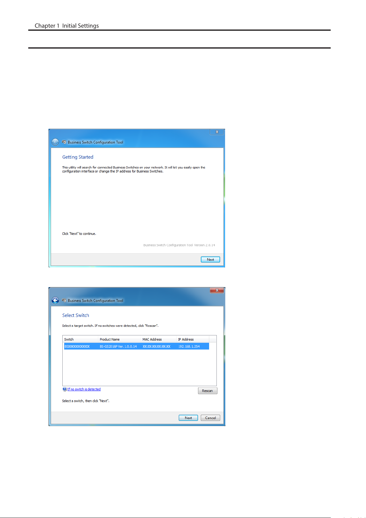
Change Switch’s IP Address
Chapter 1 Initial Settings
To enter Settings, the switch’s web user interface, the switch’s IP address should belong to the same segment as your
PC’s IP address.
1 Connect the switch to your PC and your network with an Ethernet cable (sold separately). Confirm that link/act
LED of the connected port is on.
2 Double-click the “Business Switch Configuration Tool” icon to open Business Switch Configuration Tool.
3 Click [Next] to start searching for the switch.
4 Select the switch and click [Next].
7
Page 9
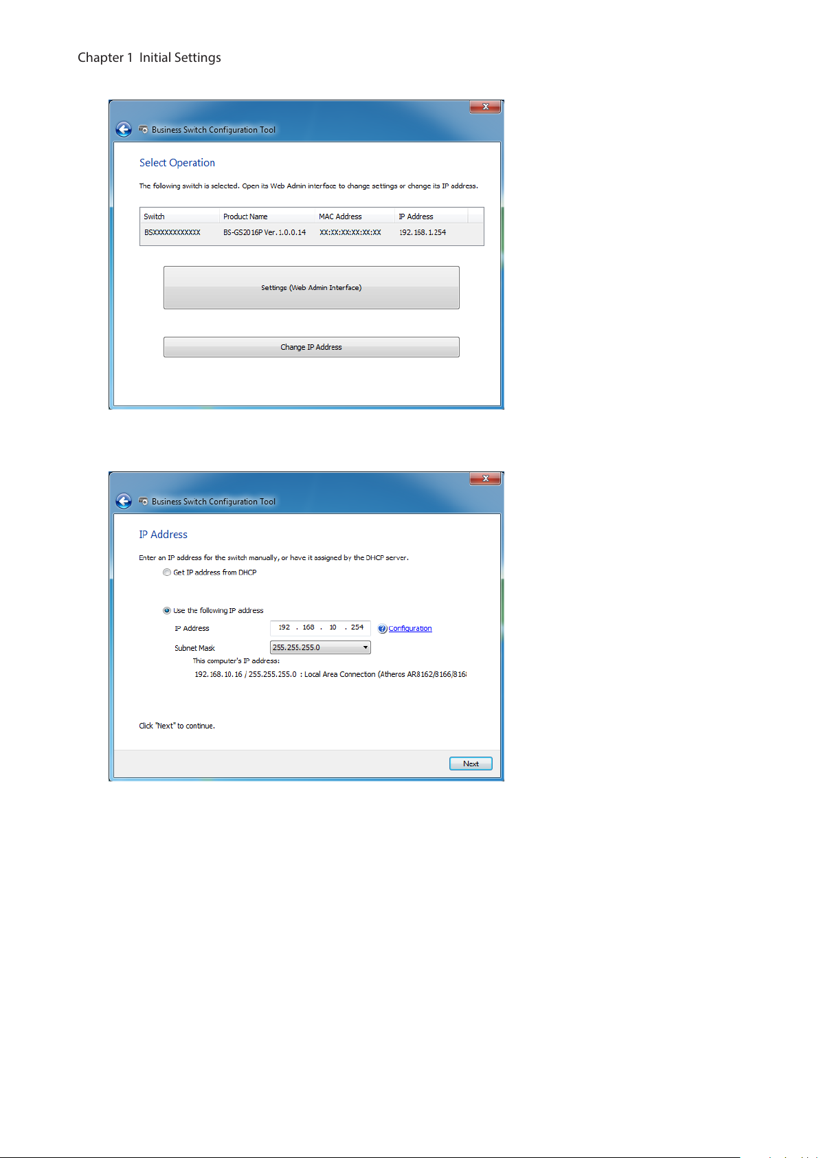
5 Click [Change IP Address].
Chapter 1 Initial Settings
6 Configure the switch’s IP address to match the segment of the IP address of your PC and click [Next]. If the
password input screen is displayed, enter “password” and click [Next].
7 Click [Back to Select Switch].
8
Page 10
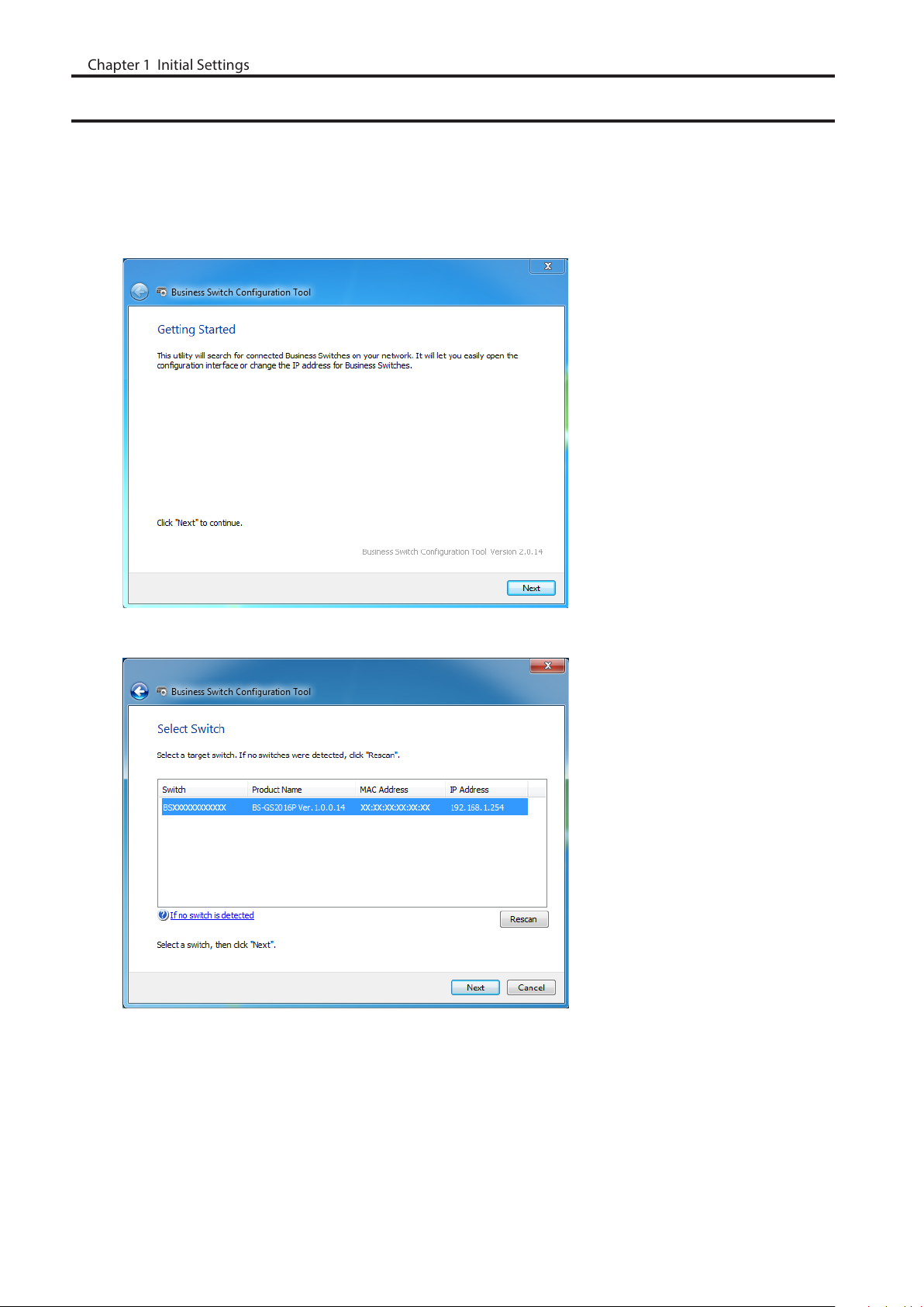
Open Settings
Chapter 1 Initial Settings
1 Configure the switch’s IP address referring to the “Change Switch’s IP Address” section above.
2 Double-click the “Business Switch Configuration Tool” icon to open Business Switch Configuration Tool.
3 Click [Next] to start searching for the switch.
4 Select the switch and click [Next].
9
Page 11
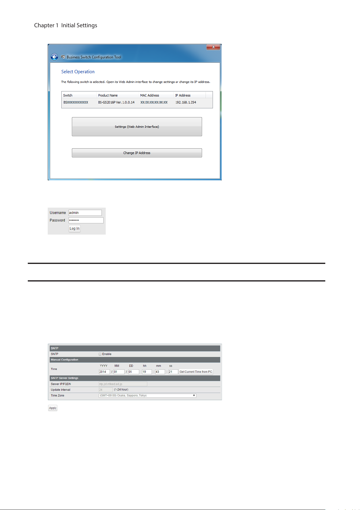
5 Click [Settings (Web Admin Interface)].
Chapter 1 Initial Settings
6 Click OK to launch a web browser and display the login screen. Enter “admin” as the username and “password”
as the password, then click [Log In].
Configure Date and Time
To configure the date and time, refer to the following procedure.
1 Open Settings.
2 Navigate to [Basic] - [Date & Time].
3 Configure each settings and click [Apply].
Note: Enter the IP address or FQDN of the NTP server to change the NTP server. You may enter 4-255
characters. To use FQDN, you have to configure DNS settings separately.
10
Page 12
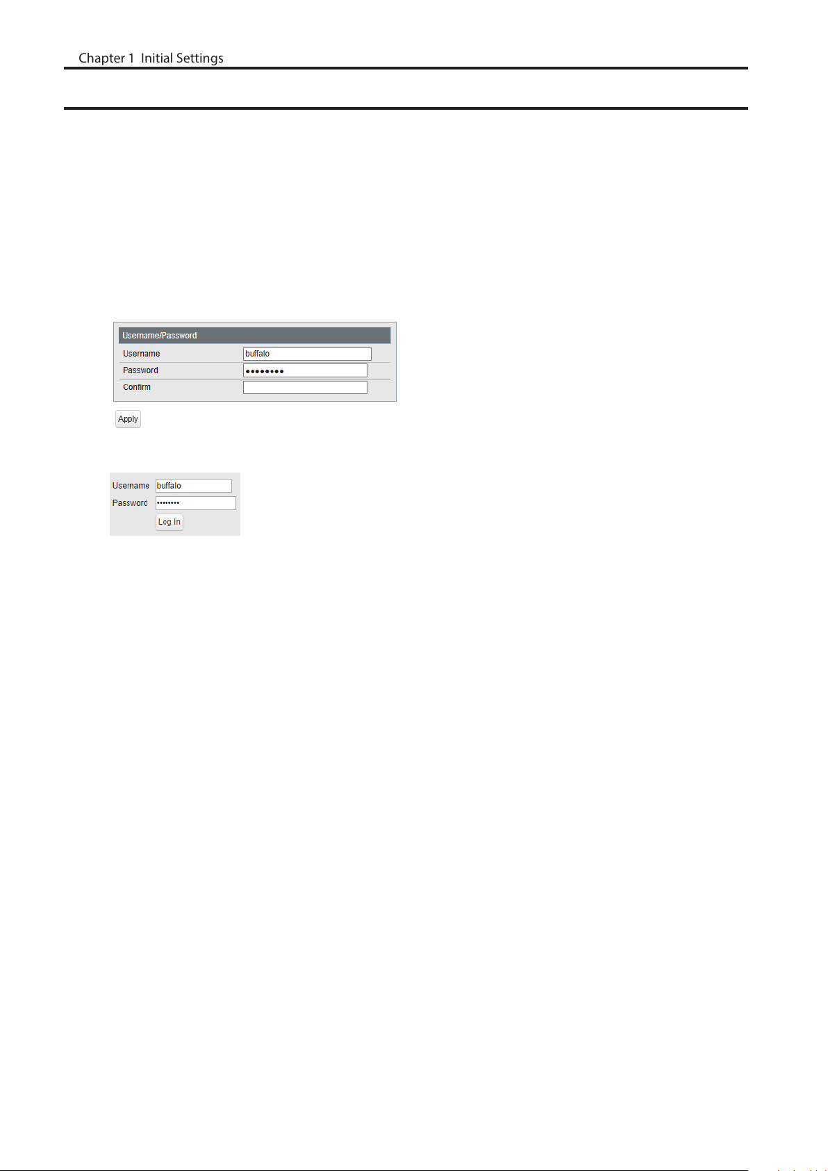
Change Username and Password
Chapter 1 Initial Settings
To change the default username and password from “admin” and “password”, refer to the following procedure.
1 Open Settings.
2 Navigate to [Basic] - [System Security] - [Administration Account].
3 Enter your new username and password (also fill the “Confirm” field), then click [Apply].
Notes:
• For the new username, you may enter up to 8 alphanumeric characters, hyphens (-), and underscores (_).
• For the new password, you may enter up to 32 alphanumeric characters, hyphens (-), and underscores (_).
4 Enter the new username and password, then click [Log In].
11
Page 13
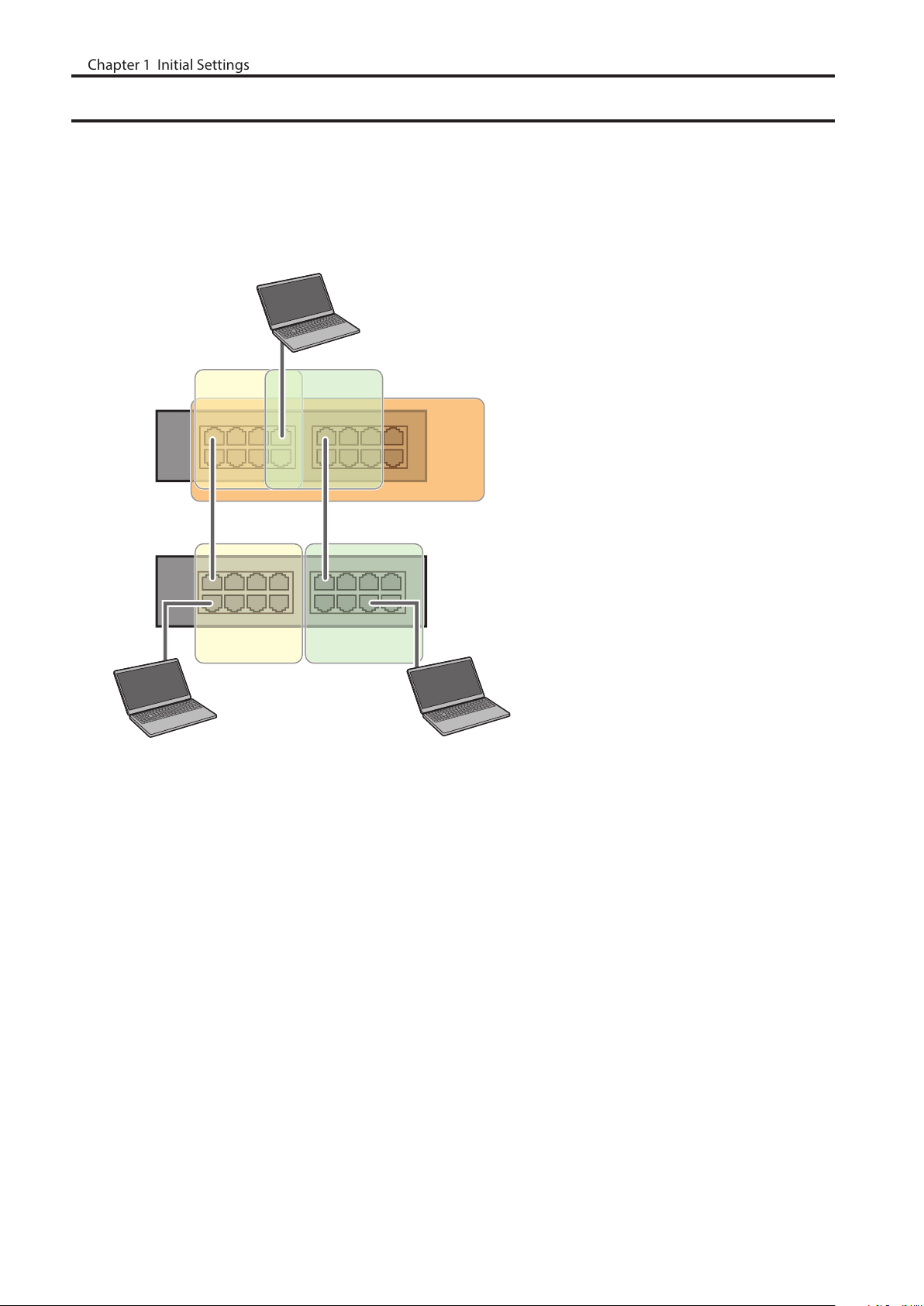
MAC Address Learning
Chapter 1 Initial Settings
This switch uses SVL (Shared VLAN Learning) to learn MAC addresses. SVL is a method that retains a shared MAC
address table for the entire switch. It differs from IVL, which retains a MAC address table for each VLAN. Be sure you
understand how SVL works before you create a VLAN with the switch.
Differences between Operation of SVL and IVL
PC3
(VLAN 1, 2,3
PVID 3)
VLAN 1
Switch 1
Switch 2
VLAN 1 VLAN 2
PC1 (VLAN 1, PVID 1) PC2 (VLAN 2, PVID 2)
SVL
VLAN 2
VLAN 3
When PC 1 and PC 3 communicate, PC 3 is learned by port 1 on switch 2 so PC 2 and PC 3 cannot communicate.
IVL
When PC 1 and PC 3 communicate, PC 3 is learned by both VLAN 1 and VLAN 2 so PC 2 and PC 3 can communicate.
However, frames sent from PC 3 to PC 1 are also delivered to PC 2.
12
Page 14

Chapter 2 Settings
Chapter 2 Settings
Refer to the “Open Settings” section in chapter 1 to access Settings.
Menu
System Information Displays the switch’s information.
Basic
System Configure the switch’s name, location, and contact.
VLAN
Routing
SNMP
LLDP
MAC Addresses
Port Settings
System Security
Date & Time Configure date and time by using SNTP or manually.
PoE
(PoE-compatible
switches only)
Advanced
VLAN Settings
VLAN Ports Configure PVID (Port VLAN ID).
L2/L3 Settings Switch between L2 mode and L3 mode.
Static Routing
(L3 mode only)
SNMP Community Table Configure SNMP community table.
SNMP Host Table Configure SNMP host table.
SNMP Trap Configure SNMP trap.
SNMPv3 User Configure SNMPv3 user information.
LLDP Properties Configure LLDP.
LLDP Port Configure LLDP for each port.
LLDP-MED Port Configure LLDP-MED for each port.
Neighbor Table
Static MAC Filtering Configure static MAC address-based filtering.
Dynamic MAC Filtering Configure dynamic MAC address-based filtering.
Convert MAC Address
Static MAC Address Register static MAC addresses to the MAC address table.
MAC Address Aging Configure MAC address aging time.
Status Displays port status.
Speed/Mode Settings Configure transmission rate and flow control for each port.
Administration Account Configure administration username and password.
Access Management Configure each administration interface.
Certificate Configure certificate.
Status Displays PoE status.
PoE Profiles Configure PoE settings.
Power Profiles Configure power saving schedules.
Confirm VLAN status and create new VLAN. This switch’s IP
address can also be configured on this page.
Configure the gateway to access the specific destination.
Displays the information of LLDP-compatible products
connected to the switch.
Add dynamic MAC addresses to the static MAC address table to
filter them in static MAC filtering.
13
Page 15

QoS Settings Configure QoS priority.
Chapter 2 Settings
QoS Mapping Configure QoS mapping for each priority.
VoIP Auto Priority Configure priority for SIP, H.323, SCCP.
DiffServ
IPv4/MAC Policy Create DiffServ policies based on IPv4 or MAC addresses.
QoS
Security
Authentication
Port Trunking Configure port trunking.
Traffic Control Configure traffic storm control.
Mirroring Configure to monitoring traffic.
Spanning Tree
Protocol
IGMP
MLD
ACL
Loop Prevention Configure loop prevention settings.
DHCP Relay
(L3 mode only)
Management
Update Firmware Update firmware from a local file.
IPv6 Policy Create DiffServ policies based on IPv6 addresses.
Port Settings Configure ports to assign each DiffServ policy.
IPv4/MAC Priority
IPv6 Priority
Status Displays DiffServ status.
Auto DoS Attack
Prevention
DHCP Snooping Configure DHCP snooping.
DHCP Table
Status Displays authentication server status.
RADIUS Configure authentication (RADIUS) server.
Port Authentication Configure authentication for each port.
STP Settings Configure STP/RSTP/MSTP.
Status Displays STP/RSTP/MSTP status of each port.
Ports Configure STP/RSTP/MSTP priority for each port.
Status Displays IGMP status.
IGMP Settings Configure IGMP snooping.
IGMP Querier Configure IGMP querier.
IGMP Router Port Specify ports to connect to multicast routers.
Status Displays MLD status.
MLD Settings Configure MLD snooping.
MLD Querier Configure MLD querier.
MLD Router Port Specify ports to connect to multicast routers.
ACL Wizard Configure ACL with wizard.
MAC ACL Create MAC address-based ACL.
IPv4 ACL Create IPv4 address-based ACL.
IPv6 ACL Create IPv6 address-based ACL.
Ports Configure ports to assign each ACL group.
IPv4/MAC Priority Configure priority of each IPv4 or MAC ACL group.
IPv6 Priority Configure priority of each IPv6 ACL group.
Status Displays ACL status.
Configure priority of each DiffServ policy based on IPv4 or MAC
address.
Configure priority of each DiffServ policy based on IPv6
address.
Configure to drop specified packets.
Displays the list of DHCP clients that obtain IP addresses from a
DHCP server via the switch.
Configure DHCP relay settings.
14
Page 16
Dual Image Select a firmware image to be read when booting.
Chapter 2 Settings
Back Up and Restore Settings Save settings to a file or restore settings from a file.
Reboot Reboot the switch.
Initialize Initialize the switch.
ARP Table
(L3 mode only)
MAC Address
Table
Statistics Displays the switch’s statistics.
Logs Displays log information.
Syslog Settings Configure to transfer logs to syslog server.
Network Diagnostics Execute communication test to the specified IP address.
Cable Diagnostics
Port Order Displays the ARP table ordered by ports.
IP Address Order Displays the ARP table ordered by IP addresses.
Port Order Displays the MAC address table ordered by ports.
MAC Order Displays the MAC address table ordered by MAC addresses.
Confirm abnormalities of each Ethernet cable connected to the
switch.
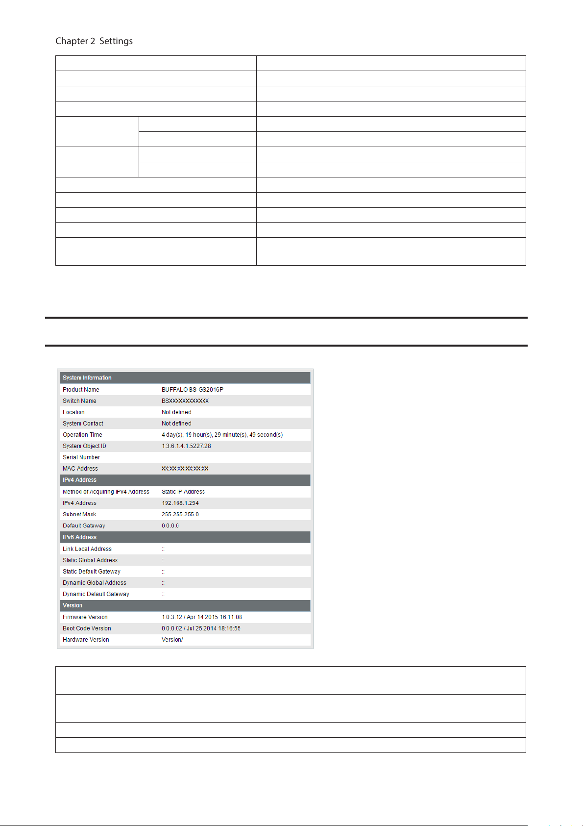
System Information
Displays the switch’s information.
System Information
IPv4 Address
IPv6 Address Displays information such as the switch’s IPv6 addresses and default gateways.
Version Displays the switch’s firmware, boot code, and hardware version.
Displays system information such as the switch name, serial number, and MAC
address.
Displays information such as the switch’s IPv4 address, subnet mask, and default
gateway.
15
Page 17
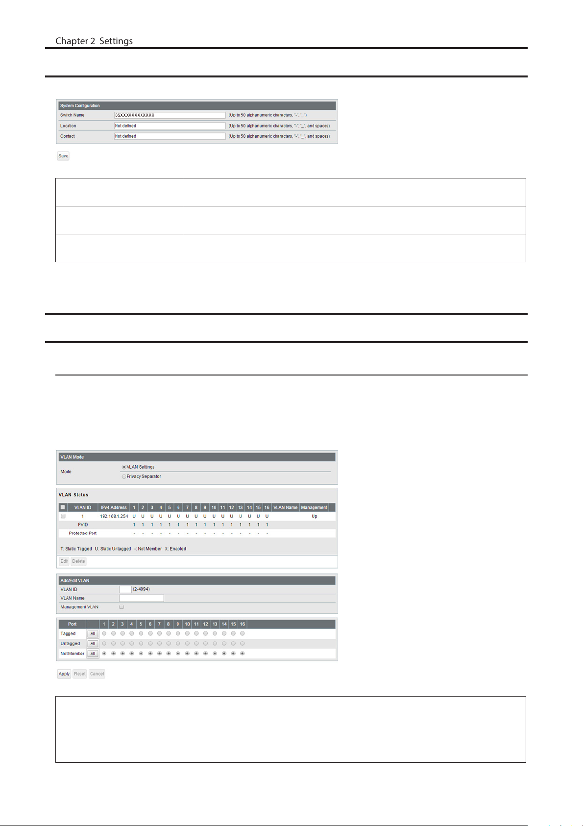
System
Chapter 2 Settings
Configure the switch’s name, location, and contact.
Switch Name
Location
Contact
Enter the switch’s name. You may enter up to 50 alphanumeric characters,
hyphens, and underscores.
Enter the location of the switch. You may enter up to 50 alphanumeric characters,
hyphens, underscores, and spaces.
Enter the contact information of the switch. You may enter up to 50 alphanumeric
characters, hyphens, underscores, and spaces.
VLAN
VLAN Settings
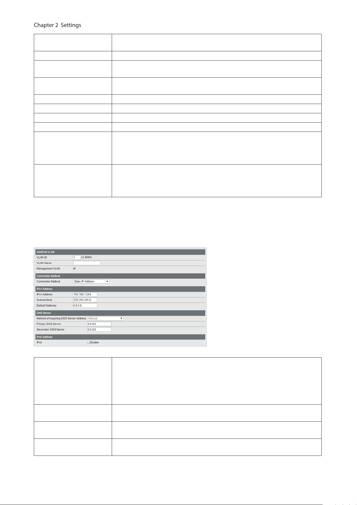
Confirm VLAN status and configure new VLAN. The switch’s IP address, default gateway, and DNS server can also be
configured on this page.
In L2 mode
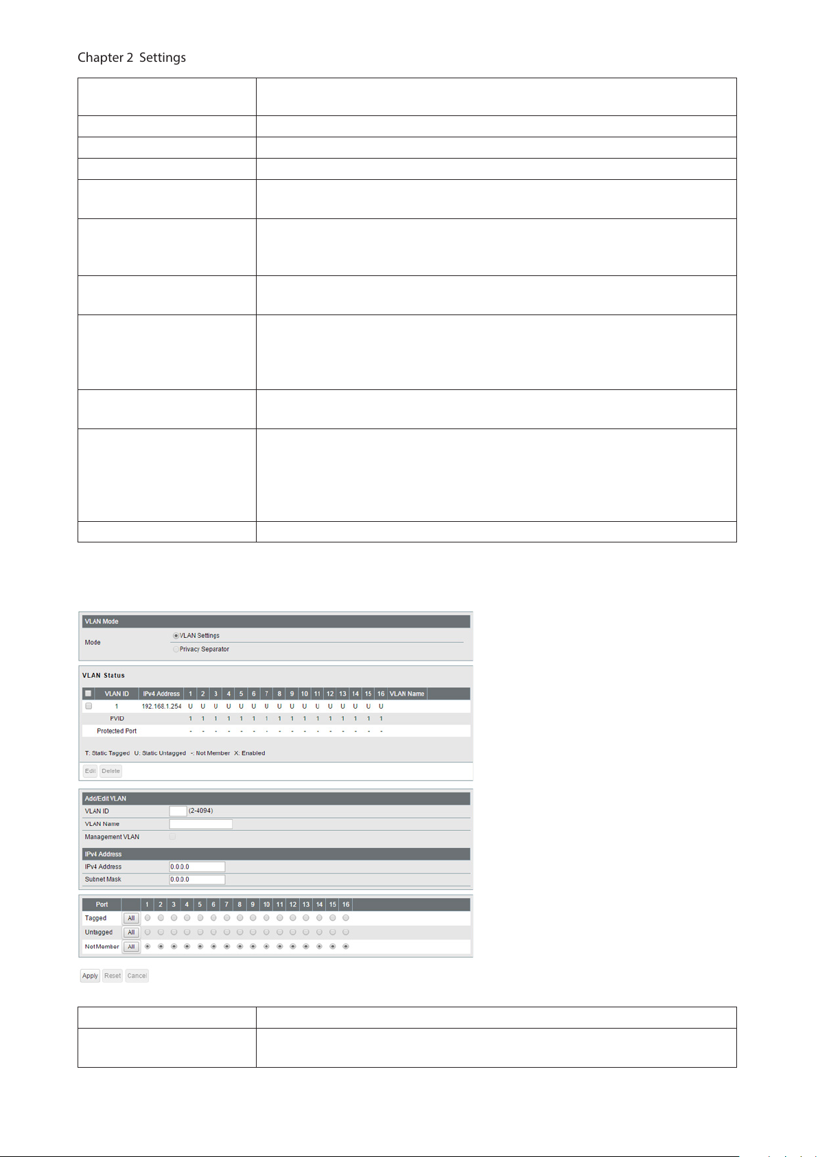
Mode
Select a VLAN mode from “VLAN Settings” or “Privacy Separator”. Privacy separator
is a mode that enables communication to the router from a port but blocks
communication between ports.
Note: VLAN and privacy separator cannot be used at the same time.
16
Page 18
VLAN Status
Chapter 2 Settings
VLAN ID Specify VLAN ID from 2-4094.
VLAN Name
Management VLAN
Tagged Select when you assign the port to tag member.
Untagged Select when you assign the port to untag member.
Not Member Select when you do not assign the port to any member.
Reset Click to reset the changes to the previous settings.
Uplink
Downlink
Note: In privacy separator mode, only the device connected to an uplink port can open Settings. If you configure
the port that your PC is connected as a downlink port, you cannot open Settings any more.
Displays current VLAN and PVID (Port VLAN ID) status. Click [Edit] to edit the VLAN
selected. Click [Delete] to delete the VLAN selected. VLAN 1 cannot be deleted.
Enter the VLAN name. You may enter up to 17 alphanumeric characters, hyphens,
and underscores.
Check it if the VLAN is a management VLAN. Only devices which belong to the
management VLAN can open Settings.
Appears when “Privacy Separator” is selected.
A router should be connected to the uplink port to connect to the Internet.
Uplink ports can communicate with all downlink ports. Specify at least 1 port to
an uplink port.
Appears when “Privacy Separator” is selected.
Downlink ports are the ones which each device connected to. Downlink ports can
communicate with uplink ports, but cannot communicate with each downlink
port.
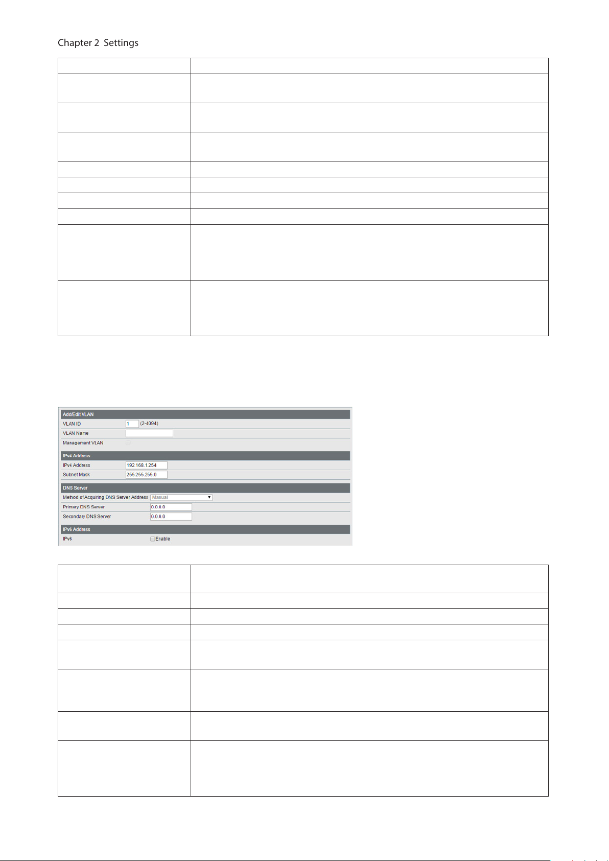
The following screen is displayed when you select VLAN 1 and click [Edit] or click [Edit] next to the IP address field in
privacy separator mode.
Select a method of obtaining the switch’s IP address.
Connection Method
IPv4 Address
Subnet Mask
Default Gateway
Static IP Address
Enter the IP address manually.
Obtain from DHCP Server
Obtain the switch’s IP address from DHCP server.
Enter the switch’s IPv4 address if you select [Static IP Address] as the connection
method.
Enter the switch’s subnet mask if you select [Static IP Address] as the connection
method.
Enter the switch’s default gateway if you select [Static IP Address] as the
connection method.
17
Page 19
Method of Acquiring DNS
Chapter 2 Settings
Server Address
Primary DNS Server Enter the primary DNS server’s IP address.
Secondary DNS Server Enter the secondary DNS server’s IP address.
IPv6 Check “Enable” to enable IPv6.
Obtain IPv6 address
automatically
DHCPv6 Client
Link Local Address
Static Global Address
Static Default Gateway
Dynamic Global Address
Dynamic Default Gateway Displays the default gateway obtained from router advertisement.
Select a method of obtaining the DNS server’s IP address.
Check “Enable” if the switch need to obtain router advertisement from IPv6compatible router.
Check “Enable” if using DHCPv6 client. When “Rapid Commit” is checked, the
communication speed with DHCPv6 server will be increased if the DHCPv6 server
is also compatible with rapid commit.
Displays the switch’s link local address. This is generated automatically when IPv6
is enabled.
Enter the global address and prefix length to configure an IPv6 address manually.
The prefix length may contain 1-128. When “EUI-64” is checked, the bottom 64-bit
of the IPv6 address will be generated automatically based on the switch’s MAC
address, in accordance with Modified EUI-64 (RFC4291).
Enter the default gateway to configure an IPv6 default gateway manually. The
default gateway prefix should be the same as the static global address.
Displays the dynamic global address obtained from DHCPv6 or router
advertisement.
The address with the trailing “SF” means that the address was obtained from
DHCPv6. The address with the trailing “SL” means that the address was obtained
from router advertisement.
In L3 mode
Mode Privacy separator cannot be used when the switch is in L3 mode.
VLAN Status
Displays current VLAN and PVID (Port VLAN ID) status. Click [Edit] to edit the VLAN
selected. Click [Delete] to delete the VLAN selected. VLAN 1 cannot be deleted.
18
Page 20
VLAN ID Specify the VLAN ID from 2-4094.
Chapter 2 Settings
VLAN Name
Management VLAN
IPv4 Address
Tagged Select when you assign the port to tag member.
Untagged Select when you assign the port to untag member.
Not Member Select when you do not assign the port to any member.
Reset Click to reset the changes to the previous settings.
Uplink
Downlink
Note: In privacy separator mode, only the device connected to an uplink port can open Settings. If you configure
the port that your PC is connected as a downlink port, you cannot open Settings anymore.
Enter the VLAN name. You may enter up to 17 alphanumeric characters, hyphens,
and underscores.
If an IP address is assigned to the VLAN, that VLAN will become a management
VLAN in L3 mode.
Enter an IPv4 address and a subnet mask to assign them to the VLAN. Up to 32
VLANs that a unique IPv4 addresses is assigned can be created.
Appears when “Privacy Separator” is selected.
A router should be connected to the uplink port to connect to the Internet.
Uplink ports can communicate with all downlink ports. Specify at least 1 port to
an uplink port.
Appears when “Privacy Separator” is selected.
Downlink ports are the ones which each device connected to. Downlink ports can
communicate with uplink ports, but cannot communicate with each downlink
port.
The following screen is displayed when you select VLAN 1 and click [Edit].
Method of Acquiring DNS
Server Address
Primary DNS Server Enter the primary DNS server’s IP address.
Secondary DNS Server Enter the secondary DNS server’s IP address.
IPv6 Check “Enable” to enable IPv6.
Obtain IPv6 address
automatically
DHCPv6 Client
Link Local Address
Static Global Address
Select a method of obtaining the DNS server’s IP address.
Check “Enable” if the switch need to obtain router advertisement from IPv6compatible router.
Check “Enable” if using DHCPv6 client. When “Rapid Commit” is checked, the
communication speed with the DHCPv6 server will be increased if the DHCPv6
server is also compatible with rapid commit.
Displays the switch’s link local address. This is generated automatically when IPv6
is enabled.
Enter the global address and prefix length to configure an IPv6 address manually.
The prefix length may contain 1-128. When “EUI-64” is checked, the bottom 64-bit
of the IPv6 address will be generated automatically based on the switch’s MAC
address, in accordance with Modified EUI-64 (RFC4291).
19
Page 21
Static Default Gateway
Chapter 2 Settings
Dynamic Global Address
Dynamic Default Gateway Displays the default gateway obtained from router advertisement.
Note: In L3 mode, you can configure the default gateway from the [Routing] - [Static Routing] page.
Enter the default gateway to configure an IPv6 default gateway manually. The
default gateway prefix should be the same as the static global address.
Displays the dynamic global address obtained from DHCPv6 or router
advertisement.
The address with the trailing “SF” means that the address was obtained from
DHCPv6. The address with the trailing “SL” means that the address was obtained
from router advertisement.
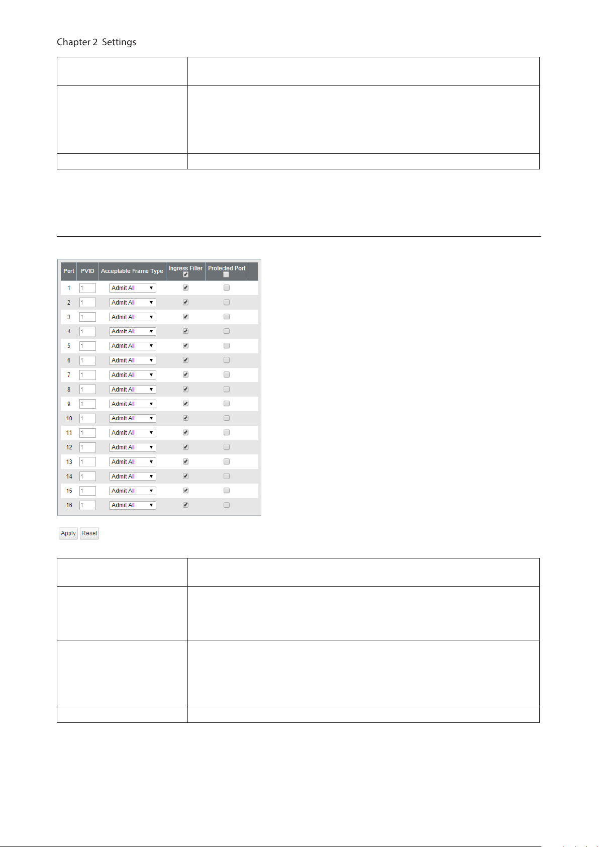
VLAN Ports
Configure PVID (Port VLAN ID).
PVID
Acceptable Frame Type
Ingress Filter
Protected Port “Protected Port” enabled ports cannot communicate with each other.
Specify the port VLAN ID. The received untagged frames will be recognized as the
specified VLAN ID. (1-4094)
Admit All
Receive both untagged and tagged frames.
Tag Only
Receive tagged frames only and drop untagged frames.
Enable
Drop frames if the received frame’s VLAN ID is not a member of incoming port’s
VLAN.
Disable
All tagged and untagged frames will be received.
20
Page 22
Routing
Chapter 2 Settings
L2/L3 Settings
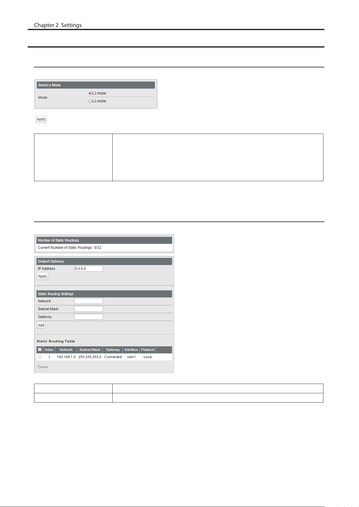
Configure the layer mode of the switch.
Specify the layer mode from the following.
Mode
Note: Switching the mode will delete static routing settings and all VLANs except VLAN 1.
L3 mode
The switch works as a layer 3 switch.
L2 mode
The switch works as a layer 2 switch.
Static Routing
Displayed only when the switch is in L3 mode. Configure the gateway to reach the specified network.
Number of Static Routings Displays the number of enabled static routings.
Default Gateway Enter the IP address of the gateway to reach an unspecified network.
21
Page 23
Add the static routing setting to the table by entering the following items. Up to
Chapter 2 Settings
32 static routes can be created.
Network
Static Routing Table
Setting
Static Routing Table Displays the static routing information.
Enter the IP address of the network that you need to configure the static routing
for.
Subnet Mask
Enter the subnet mask of the network.
Gateway
Enter the IP address of the gateway to reach the specified network.
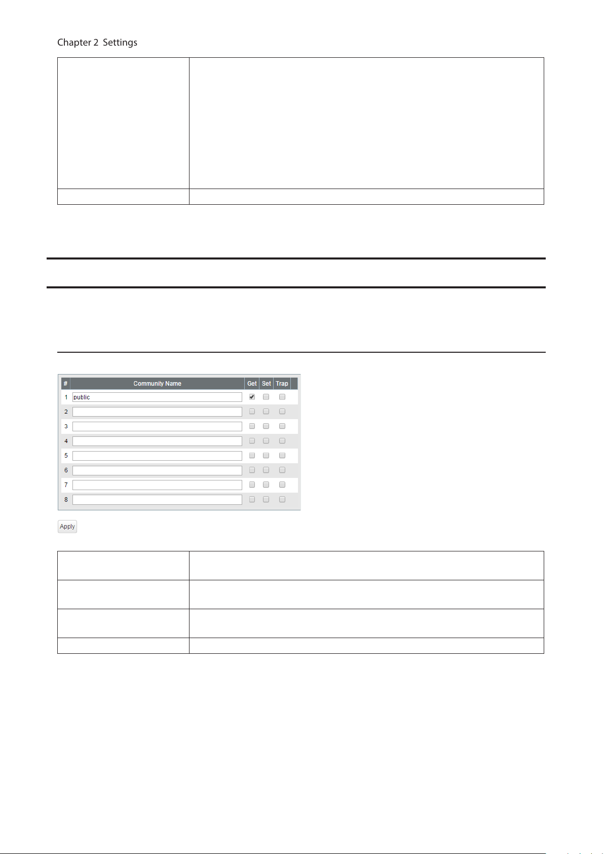
SNMP Settings
To use SNMP, SNMP monitoring software is needed.
SNMP Community Table
Configure SNMP community table.
Community Name
Get
Set
Trap If checked, communication members can receive SNMP traps.
Enter the community name. You may enter up to 31 alphanumeric characters,
hyphens, and underscores.
If checked, community members are allowed to read the switch’s SNMP
information.
If checked, community members are allowed to write the switch’s SNMP
information.
22
Page 24
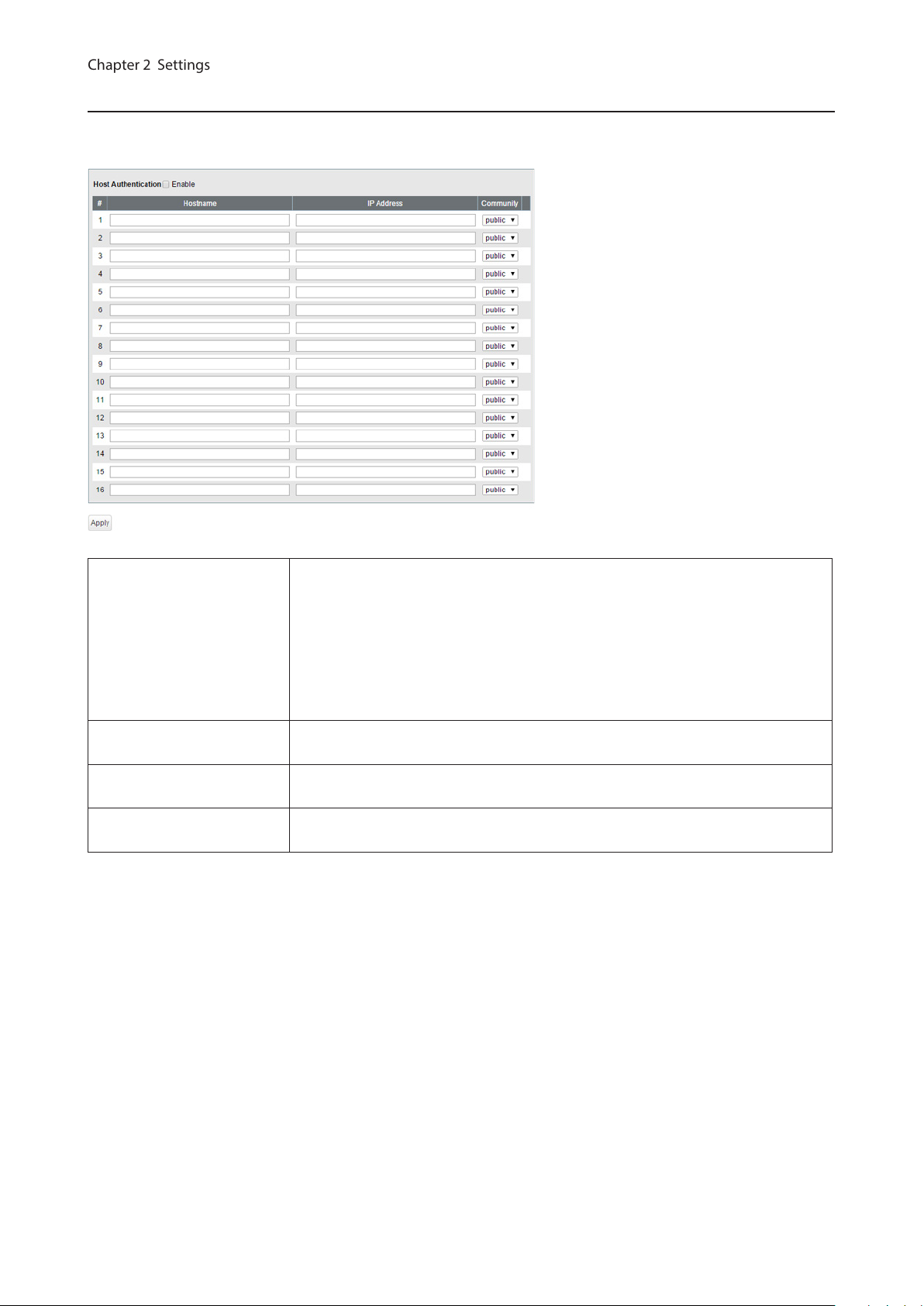
SNMP Host Table
Chapter 2 Settings
Configure the SNMP host table.
Note: To delete the registered host, make “Hostname” and “IP Address” field blank and click [Apply].
Host Authentication
Hostname
IP Address
Community
Enable/disable SNMP host authentication.
Enable
SNMP service will be provided from SNMP manager only. Read/write authority
depends on the community.
Disable
Receive SNMP requests from any hosts. Read/write authority depends on the
community.
Enter a hostname to permit SNMP requests. You may enter 1-31 alphanumeric
characters, hyphens, and underscores.
Enter an IPv4/IPv6 address of the host. To communicate with the host using an
IPv6 address, enable IPv6 in advance.
Select the host’s community. Communities should be configured on the [SNMP
Community Table] page in advance.
23
Page 25

SNMP Trap
Chapter 2 Settings
Configure SNMP traps.
Note: To use SNMP traps, register the host to the host table on the [Basic] - [SNMP] - [SNMP Host Table] page and
enable “trap” for that community.
Compatible traps:
0 coldStart
1 warmStart
2 LinkDown (Link Up/Down)
3 LinkUp (Link Up/Down)
4 authenticationFailure (Authentication Trap)
6 topoligyChange (STP)
7 Loop detection (Loop Detection)
Private MIB OID: 1.3.6.1.4.1.5227.28.1.1.1
8 Trunk (Trunk)
Private MIB OID: 1.3.6.1.4.1.5227.28.1.1.2 (the value differs depending on the trunk’s link status as below)
1.3.6.1.4.1.5227.28.1.2.1 (trunk key 1-8)
1.3.6.1.4.1.5227.28.1.2.2 (link up: 1, link down: 2)
All traps can be enabled/disabled except “coldStart” and “warmStart”.
SNMP Trap Enable or disable all of the following traps.
Authentication Trap
Link Up/Down If enabled, the trap will be sent when link up/down of the port is detected.
STP
Loop Detection If enabled, the trap will be sent when the loop is detected.
Trunk If enabled, the trap will be sent when the trunk is configured or unconfigured.
If enabled, the trap will be sent when SNMP is requested from an unallowed IP
address.
If enabled, the trap will be sent when STP/RSTP/MSTP topology change is
occurred.
24
Page 26
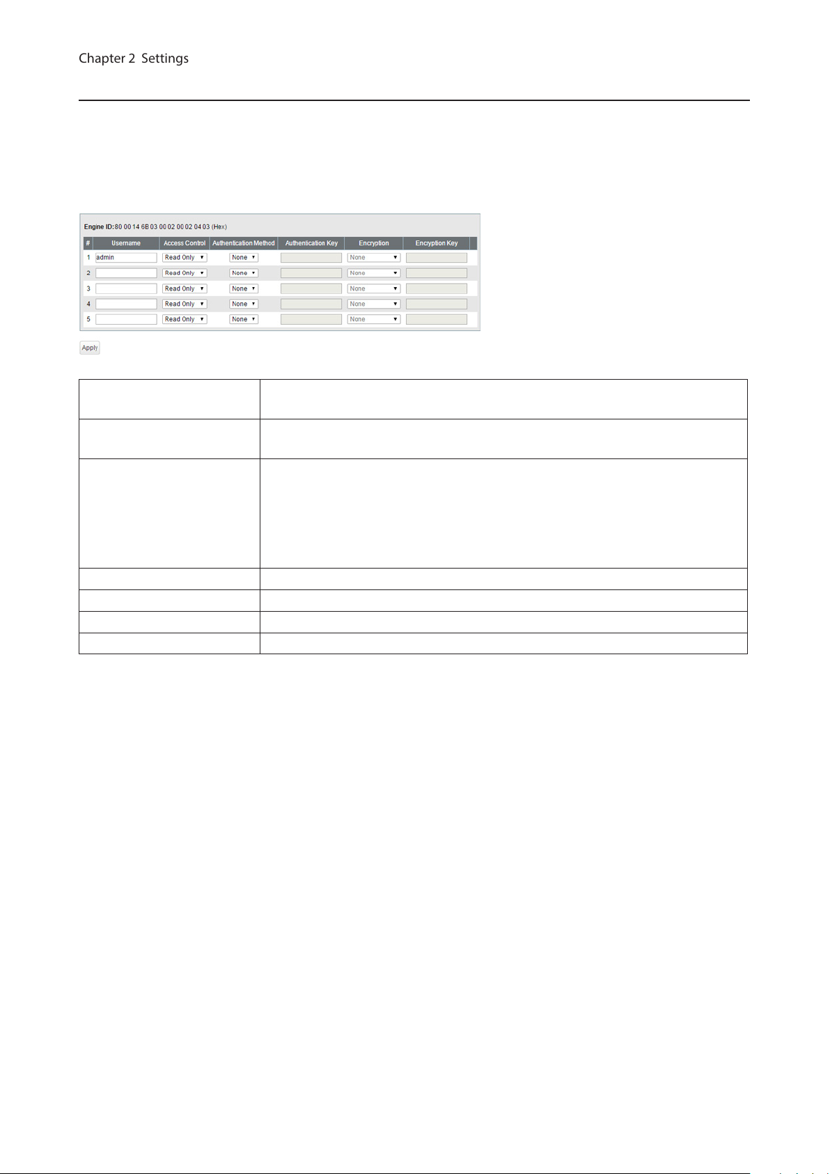
SNMPv3 User
Chapter 2 Settings
Configure information of users who are authenticated with SNMPv3. SNMPv3 will authenticate users using
username and the authentication can be encrypted. This switch is compatible with the following authentication and
encryption method.
Authentication method: HMAC-MD5-96/HMAC-SHA-96
Encryption method: CBC-DES/CFB-AES-128
Engine ID
Username
Access Control
Authentication Method Configure the authentication method.
Authentication Key Enter the key phrase compatible with the authentication method.
Encryption Configure the encryption method.
Encryption Key Enter the key phrase compatible with the encryption method.
This is the switch’s unique ID to identify SNMP engine. This ID will be notified to
other side when SNMPv3 communication is done.
Enter the username to authenticate. The username should be up to 32
alphanumeric characters, hyphens (-), and underscores (_).
Limit the access depending on the user.
Read Only
Prohibit writing.
Read/Write
Permit any access.
25
Page 27
LLDP
Chapter 2 Settings
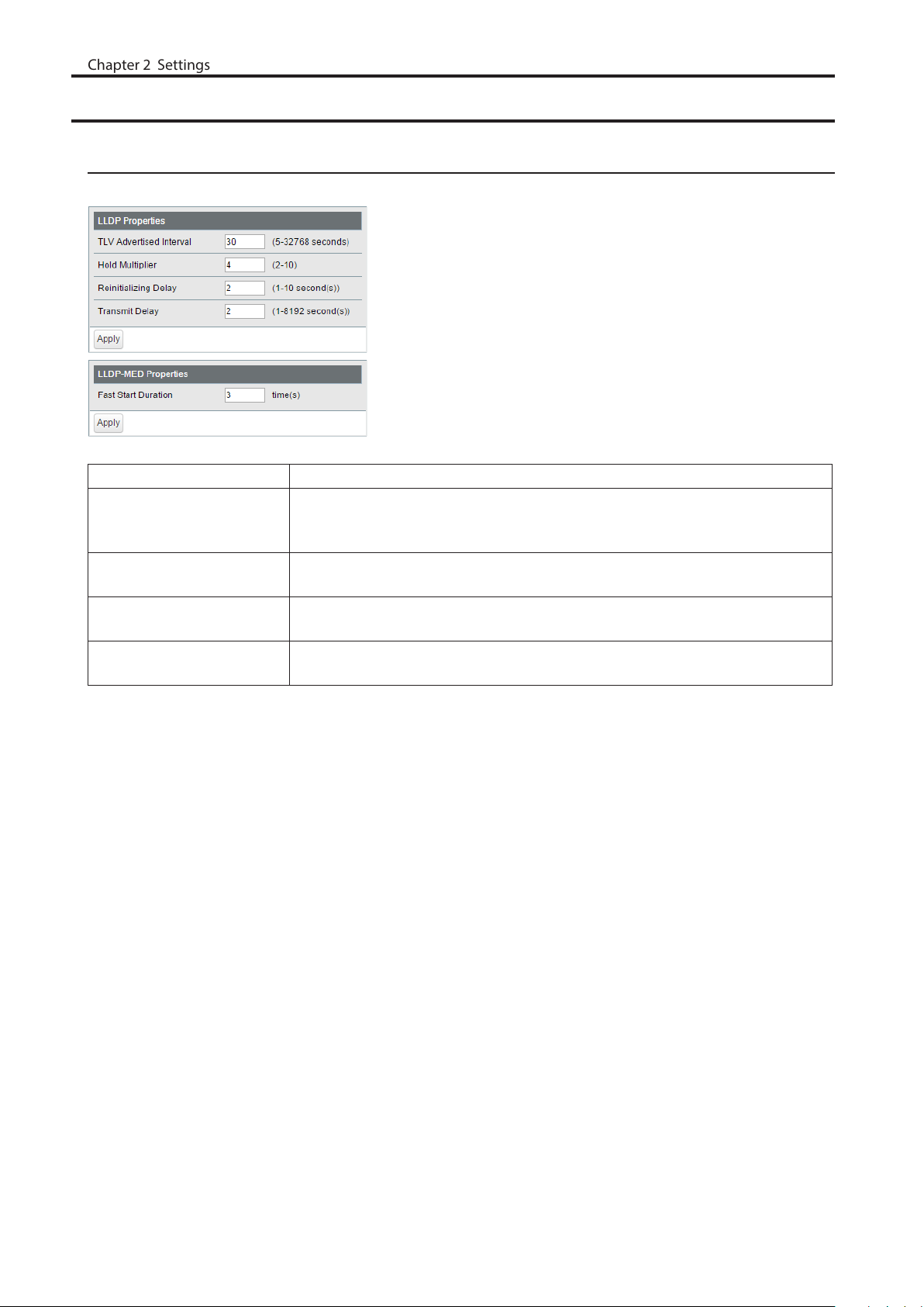
LLDP Properties
Configure LLDP.
TLV Advertised Interval Enter the interval of sending LLDP packets. (5-32768 seconds)
Enter the amount of time of TTL (Time To Live: the time that LLDP packets
Hold Multiplier
Reinitializing Delay
Transmit Delay
Fast Start Duration
are held before the packets are discarded) measured in multiples of the TLV
advertised interval. (2-10)
Enter the time that passes between disabling and reinitializing LLDP. (1-10
seconds)
Enter the time that passes between changing the LLDP settings and transmitting
LLDP frame. (1-8192 seconds)
Enter the number of times that LLDP packets are sent when the LLDP-MEDcompatible device is detected.
26
Page 28
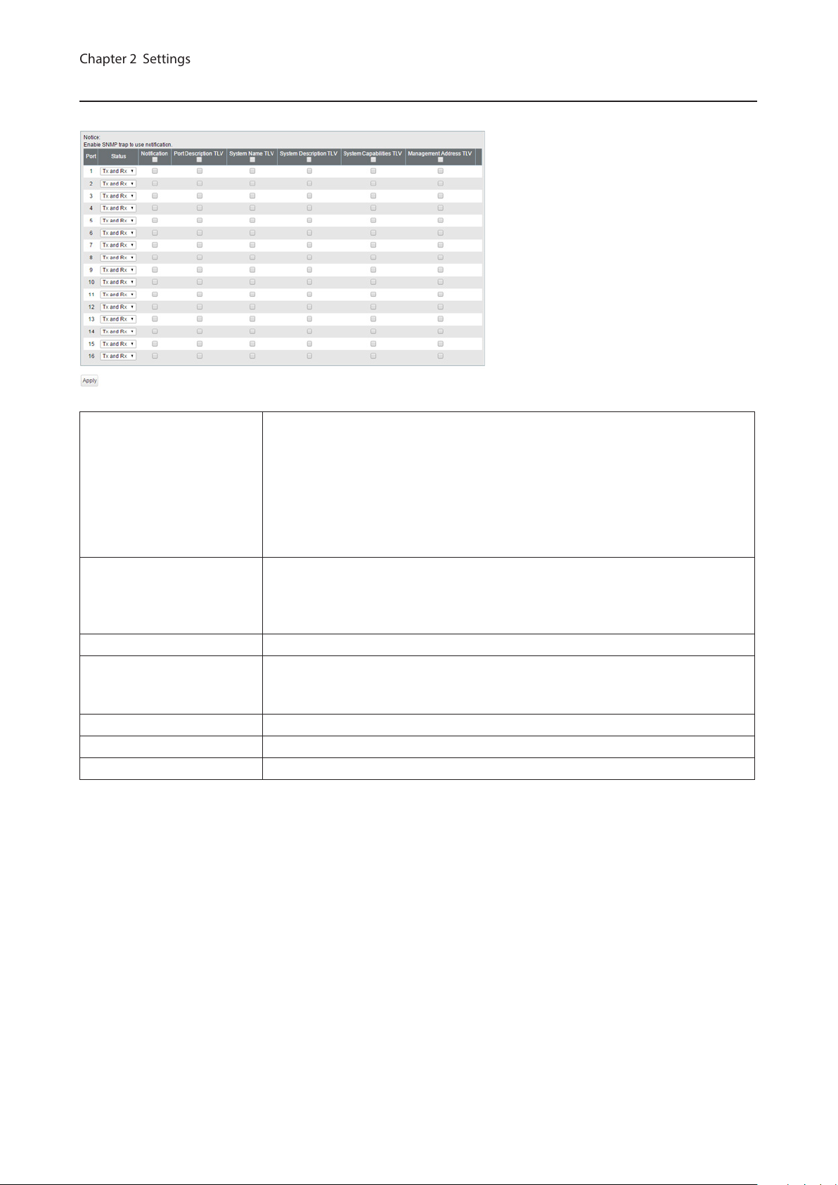
LLDP Port
Chapter 2 Settings
Configure LLDP for each port.
Status
Notification
Disable
Disable LLDP.
Tx Only
Enable transmitting LLDP packets only.
Rx Only
Enable receiving LLDP packets only.
Tx and Rx
Enable transmitting and receiving LLDP packets.
If enabled, SNMP traps will be sent to the SNMP server when the neighbor table is
updated.
Note: To use notification, configure SNMP manager and SNMP trap settings.
Port Description TLV If enabled, the port information (port number) will be included in LLDP packets.
If enabled, the switch name will be included in LLDP packets.
System Name TLV
Note: The switch name can be configured on the [Basic] - [System] page.
System Description TLV If enabled, the product name will be included in LLDP packets.
System Capabilities TLV If enabled, the system capabilities will be included in LLDP packets.
Management Address TLV If enabled, the switch’s IP address will be included in LLDP packets.
27
Page 29

LLDP-MED Port
Chapter 2 Settings
Configure LLDP-MED for each port.
If enabled, LLDP-MED will be transmitted.
Status
Notification
Capabilities TLV If enabled, the capabilities will be included in LLDP packets.
Network Policy TLV If enabled, the network policy will be included in LLDP packets.
Extend Power TLV
Software Revision TLV If enabled, the firmware version will be included in LLDP packets.
Note: To use this functionality, configure the status to [Tx Only] or [Tx and Rx] on
the [LLDP Port] page.
If enabled, the SNMP trap will be sent to the SNMP server when the LLDP-MED
information in the neighbor table is updated.
Note: To use notification, configure SNMP manager and SNMP trap settings.
If enabled, the extend power will be included in LLDP packets.
Note: This functionality is compatible with PoE switches only.
28
Page 30

Neighbor Table
Chapter 2 Settings
Displays the information of the LLDP-compatible devices connected to the switch.
MSAP Entry # Displays the entry number of the detected devices.
Local Port Displays port number that the detected devices are connected to.
Chassis ID Subtype Displays the chassis ID subtype of the detected devices.
Chassis ID Displays the chassis ID of the detected devices.
Port ID Subtype Displays the port ID subtype of the detected devices.
Port ID Displays the port ID of the detected devices.
System Name Displays the system name of the detected devices.
Note: To use this functionality, configure the status to [Rx Only] or [Tx and Rx] on the [Basic] - [LLDP] - [LLDP Port]
page.
MAC Addresses
Static MAC Filtering
Configure the filtering of MAC addresses that are registered manually. Only the frames with the registered MAC
address as a source MAC address can pass through the ports that the MAC address is registered to.
Static MAC Filtering Check “Enable” to enable static MAC filtering.
MAC Address
Port Number Select a port to apply the static MAC filter.
Static MAC Filtering Table Displays the registered MAC addresses and port numbers.
Enter the MAC address you want to filter. (Example: 00:11:22:aa:bb:cc)
Up to 16 addresses can be registered per port.
Note: This function is not compatible with multicast MAC addresses, VRRP MAC addresses (00:00:5E:00:01:XX), and
broadcast MAC addresses.
29
Page 31

Dynamic MAC Filtering
Chapter 2 Settings
Configure the dynamic MAC filtering that enables you to set the number of MAC address learn limits for each port.
Dynamic MAC Filtering Check “Enable” to enable dynamic MAC filtering.
Number Enter the number of MAC address learning limits of each port. (1-16384)
Notes:
• If the port’s “Number” field is left blank, all MAC addresses can pass through that port.
• The number of MAC address learn limits can be set between 1-16384 for each port. However, the switch can learn
16384 MAC addresses in total. If the number of MAC address is over 16384, MAC addresses will never be learned
and will be dropped.
• When both static and dynamic MAC filtering are enabled, MAC addresses in the static MAC address table are not
counted towards the number of dynamic MAC address.
30
Page 32

Convert MAC Address
Chapter 2 Settings
Add dynamic MAC addresses to static MAC filtering table to filter them in static MAC filtering.
Add to Static MAC
Filtering Table from
Dynamic MAC Address
Select a port number to display the dynamic MAC addresses that was learned
from the port. Select MAC addresses to add to the static MAC filtering table and
click [Add].
Static MAC Address
Register the static MAC address to the MAC address table. The device with a registered MAC address can
communicate only when it is connected to the specified port. You can confirm the status of static MAC addresses
registration in [Management] - [MAC Address Table].
MAC Address
Port Specify the port number to register the static MAC address.
Static MAC Address Displays the registered static MAC addresses.
Enter a MAC address. Up to 256 MAC addresses can be registered to the switch in
total.
Notes:
• This function is not compatible with multicast MAC addresses, VRRP MAC addresses (00:00:5E:00:01:XX), and
broadcast MAC addresses.
• The registered device cannot communicate when it is not connected to the specified port.
MAC Address Aging
Configure MAC address aging time. MAC address aging time is the time between the last reference of the MAC
address and deleting MAC address.
Aging Time Enter the aging time.
31
Page 33

Port Settings
Chapter 2 Settings
Status
Displays the port status.
Name Displays the port name.
Admin Displays whether the port is enabled (on) or disabled (off).
Link Status Displays whether the link is up or down.
Autonegotiation Displays whether the autonegotiation is enabled (on) or disabled (off).
Speed/Duplex Displays the speed and duplex status.
Flow Control Displays whether the flow control is enabled (on) or disabled (off).
IEEE 802.3az Displays whether IEEE 802.3az is enabled (on) or disabled (off).
APD Displays whether APD is enabled (on) or disabled (off).
Displays whether jumbo frame is enabled (on) or disabled (off).
Jumbo Frame
Note: Jumbo frames of up to 9216 frames (including header 14 bytes + FCS 4
bytes) can be forwarded.
32
Page 34

Speed/Mode Settings
Chapter 2 Settings
Configure ports settings such as the transmission rate or flow control.
Name
Admin Check to enable the port.
Mode Select the transmission rate and duplex.
Flow Control Check to enable flow control.
IEEE 802.3az Check to enable IEEE802.3az.
APD
Jumbo Frame Check to enable jumbo frame settings.
Speed/Duplex Displays the current transmission rate and duplex.
Enter the port name. You may enter up to 15 alphanumeric characters, hyphens,
underscores, and spaces.
Check to enable APD (auto power down). If enabled, power consumption of link
down ports can be reduced.
System Security
Administration Account
Configure the username and password.
Username
Password
Confirm Enter the new password again.
Enter the new username. You may enter up to 8 alphanumeric characters,
hyphens, and underscores.
Enter the new password. You may enter up to 32 alphanumeric characters,
hyphens, and underscores.
33
Page 35

Access Management
Chapter 2 Settings
Configure each administration interface.
SNMP Enable or disable SNMP administration interface.
Enable or disable HTTPS administration interface.
HTTPS
Web Session Timeout Enter the timeout period for accessing Settings using HTTP.
Maximum Web Session
Number
Port Specify the port number for HTTPS connections.
HTTPS Session Timeout Enter the timeout period for accessing Settings using HTTPS.
Maximum HTTPS Session
Number
Note: To use this functionality, upload SSL certificate on the [Basic] - [System
Security] - [Certificate] page.
Enter the number of users who can access Settings using HTTP at the same time.
Enter the number of users who can access Settings using HTTPS at the same time.
Certificate
Upload or download the certificate. For HTTPS communication, prepare a certificate by yourself, or use the
certificate automatically created on the switch.
A certificate will be automatically created on the switch when no certificate is uploaded and the switch is rebooted.
The compatible certificate types are:
Certificate Type X.509
Private Key RSA up to 2048-bit (no encryption only)
Hash Algorithm SHA1, SHA256, SHA384, SHA512
The certificate must include the private key as the following:
-----BEGIN CERTIFICATE----…
…
-----END CERTIFICATE-----
-----BEGIN RSA PRIVATE KEY----…
…
-----END RSA PRIVATE KEY-----
34
Page 36

Upload HTTPS Certificate
Chapter 2 Settings
to Switch
Download HTTPS
Certificate from Switch
SSL Certificate
Information
Upload HTTPS certificate.
Download HTTPS certificate.
Displays the uploaded certificate information. Click [Delete] to delete the
uploaded certificate.
Note: If the certificate is deleted, a certificate will be automatically created next
time the switch reboots.
Date & Time
Configure whether to manually set the date and time or automatically using a SNTP server.
SNTP Enable to automatically obtain the time from SNTP server.
Time Configure the time when SNTP is disabled.
Server IP/FQDN
Update Interval Enter the interval which time is obtained from the SNTP server.
Time Zone Configure the time zone.
Enter the SNTP server IP address or FQDN. To enter the FQDN, DNS settings must
be configured.
35
Page 37

PoE
Chapter 2 Settings
This functionality is for PoE-compatible switches only.
Status
Displays the PoE status.
Power Displays the maximum power, power being used, and available power.
Displays if PoE is enabled (on) or disabled (off).
Notes:
PoE
Status Displays the power feeding status.
Power Class Displays the connected device’s class.
Priority Displays the priority of each port.
Supplied Power Displays the supplied power of each port.
Current Displays the supplied current of each port.
• If you connect a PoE device to the switch while available power (shown to the
right of "Available") is 16000 mW (16 W) or lower, the switch will not supply PoE
power to the device.
• The maximum power of BS-GS20P series is 180000 mW (180 W).
36
Page 38

PoE Profiles
Chapter 2 Settings
Configure PoE settings for each profile that is used in [Power Profile] page.
Profile Name To change the profile name, enter a new profile name and click [Modify].
PoE Enable or disable PoE functionality.
Configure the priority of PoE power feeding. When the supplied power exceeds
Priority
High Power
Turn Off LEDs? Select “Yes” to turn off all LEDs except the power LED.
Initialize Click to initialize the selected profile.
Copy Profile Select the source and destination profiles and click [Copy Profiles] to copy them.
maximum power, the switch will supply power to the ports in the order of
priority.
Configure the high-powered power feeding function.
Disable
The switch will supply power up to 15.4 W to the 802.3af-compatible devices.
High-powered power feeding is disabled.
802.3af High Power
This is the expansion of 802.3af standard. The switch will supply power up to 15.4
W to the class 0-3 devices and up to 30 W to the class 4 devices.
802.3at
The switch will supply power up to 30 W to the 802.3at-compatible devices.
37
Page 39

Notes:
Chapter 2 Settings
• Click [Apply] to apply the current settings to all profiles.
• To use dynamic power feeding by LLDP, configure the status to [Tx and Rx] on the [Basic] - [LLDP] - [LLDP Port]
page.
• If the supplied power exceeds the maximum power, the switch will supply power to the port in the order of the
port number.
Power Profile
Configure the power saving schedule.
Manual
Switch the profile manually.
Automatic
Schedule
Manual Profile Setting Select a profile to be used when the schedule is set to [Manual].
Profiles
Schedule Displays the list of the schedule. Click [Edit Schedule] to edit the schedule.
View
The screen appears when [Edit Schedule] is clicked
Unscheduled Profile Select a profile to be used when no schedules are configured.
Specify by Select a timetable type.
Date Enter the date to add to the schedule if “Date” is selected as the timetable type.
Day of Week
Period
Switch the profile automatically in accordance with the settings below.
Note: To set to [Automatic], SNTP must be enabled. If the time cannot be
obtained from SNTP server, the configured profile will be applied in accordance
with the switch’s internal clock.
Displays the list of the profiles. Click [Edit Profiles] to edit the profile.
Note: To edit the profile, set the schedule to [Manual].
Weekly
Displays the weekly schedule.
Daily
Displays the daily schedule.
Select the day of week to add to the schedule if “Day of week and time” is selected
as the timetable type.
Select the time frame while the schedule is enabled if “Day of week and time” is
selected as the timetable type.
38
Page 40

Select a method of specifying the profile. “Copy profile from a different day”
Chapter 2 Settings
Select Profile
Profile
Use profile from
Schedule Displays the list of configured schedule.
cannot be selected when “Day of week and time” is selected as the timetable
type.
Select a profile name if “Use profile below” is selected as the method of specifying
the profile. Click [Check] to confirm each profile’s settings.
Select a day of week to copy the profile if “Copy profile from a different day” is
selected as the method of specifying the profile.
QoS
QoS Settings
Configure the priority.
QoS Check to enable QoS. Click [Show Detail] to enable/disable QoS for each port.
Configure the queue scheduling type.
Strict
Execute the queue scheduling based on strict priority. High-prioritized queues
are always forwarded strictly; low-prioritized queue will never be forwarded if any
data remains in the high prioritized queue.
Schedule Method
Priority Type Select a priority parameter from DSCP, CoS, and IP precedence.
WRR
Execute the queue scheduling based on WRR (Weighted Round Robin). This will
forward queues in order of a round robin; even lower priority queues will be
forwarded at a constant rate. The priority can be specified from 0 (lowest) to 7
(highest).
Note: Packets without VLAN tag will belong to the lowest priority queue.
39
Page 41

QoS Mapping
Chapter 2 Settings
Configure port-based priority for DSCP, CoS, and IP precedence.
Port Priority Configure the priority of each port.
DSCP Mapping Configure the DSCP priority value from 0-63.
CoS Mapping Configure the CoS priority value from 0-7.
IP Precedence Mapping Configure the IP precedence priority value from 0-7.
Priority Configure the priority from 0-7.
Note: DSCP mapping, CoS mapping, and IP precedence mapping is displayed when each type is selected.
40
Page 42

VoIP Auto Priority
Chapter 2 Settings
Configure the priority of SIP, H.323, SCCP.
VoIP Auto Priority
CoS
Check to enable VoIP auto priority. Click [Show Detail] to enable or disable this
functionality for each port.
Applied to the VoIP packets of SIP, H.323, SCCP only. If QoS is enabled, it is
handled in accordance with CoS priority.
IPv4/MAC Policy
Create DiffServ policies. IPv4 and MAC addresses can be specified here. The enabled policies will be applied when
the packet or frame enters to the switch.
Current Number of
Policies
Current Number of Active
Policies
Policy Name
Displays the number of created policies.
Displays the number of active policies.
Enter the policy name into the blank field and click [Apply] to create a new policy.
Click [Show Detail] to configure the policy in detail.
Check the created policy name, enter the new name and click [Rename] to
rename the policy.
41
Page 43

The following screen appears when [Show Detail] is clicked.
Chapter 2 Settings
Policy Name Displays the selected policy name.
CoS Adds the CoS value to the policy condition.
Adds the frame’s destination MAC address to the policy condition. For
Destination MAC Address
Source MAC Address
EtherType Adds the frame’s ether type to the policy condition.
VLAN Adds the frame’s VLAN ID to the policy condition.
Protocol Adds the packet’s protocol to the policy condition.
Destination IPv4 Address
Destination Port Adds the packet’s destination port to the policy condition.
Source IPv4 Address
Source Port Adds the packet’s source port to the policy condition.
Service Type
instructions on how to enter the address, refer to “About Address and Mask”
section below.
Adds the frame’s source MAC address to the policy condition. For instructions on
how to enter the address, refer to “About Address and Mask” section below.
Adds the packet’s destination IPv4 address to the policy condition. For
instructions on how to enter the address, refer to “About Address and Mask”
section below.
Adds the packet’s source IPv4 address to the policy condition. For instructions on
how to enter the address, refer to “About Address and Mask” section below.
Adds the packet’s service type to the policy condition. Only 1 value can be
specified when “IP DSCP” or “IP Precedence” is selected.
42
Page 44

DiffServ Policy
Chapter 2 Settings
Select the action for when the frames satisfy the condition.
Permit
Permits forwarding the frames and packets.
Deny
Discards the frames and packets.
Egress Queue
Changes the processing priority of the frames and packets.
Remark CoS
Rewrites CoS value of the frames and packets.
Remark DSCP
Rewrites DSCP value of the frames and packets.
Remark IP Precedence
Rewrites IP precedence value of the frames and packets.
Profile Action
Processes the frames and packets depending on the committed rate. If the rate
of the frames and packets is less than the committed rate, the switch will process
the frames and packets in accordance with the in-profile action. Otherwise, the
switch will process the frames and packets in accordance with the out-of-profile
action.
Committed Rate
Specify the rate to determine the process method.
Committed Burst
Specify the burst size that the switch processes in accordance with the inprofile action when the rate of frames and packets exceeds the committed rate
instantaneously. When the burst size exceeds the committed burst, the switch
will process in accordance with the out-of-profile action.
In-Profile Action
Specify the action when the rate of frames and packets is less than the committed
rate.
Out-of-profile Action
Specify the action when the rate of frames and packets exceeds the committed
rate.
About Address and Mask
This product adopts “wildcard masks”.
To configure the source MAC address or destination MAC address, refer to the following example.
• To specify the range of “00:11:22:ab:cd:00” to “00:11:22:ab:cd:ff”
Enter “00:11:22:ab:cd:00” in the address field and also enter “00:00:00:00:00:ff” in the mask field.
• To specify only “00:11:22:ab:cd:ef”
Enter “00:11:22:ab:cd:ef” in the address field and also enter “00:00:00:00:00:00” in the mask field.
To configure the source IPv4 address or destination IPv4 address, refer to the following example.
• To specify the range of “192.168.1.0” to “192.168.1.254”
Enter “192.168.1.0” in the address field and also enter “0.0.0.255” in the mask field.
• To specify only “192.168.1.1”
Enter “192.168.1.1” in the address field and also enter “0.0.0.0” in the mask field.
43
Page 45

IPv6 Policy
Chapter 2 Settings
Create DiffServ policies. IPv6 addresses can be specified here. The enabled policies will be applied when the packet
or frame enters the switch.
Current Number of
Policies
Current Number of Active
Policies
Policy Name
The following screen appears when [Show Detail] is clicked.
Policy Name Displays the selected policy name.
Destination IPv6 Address
Source IPv6 Address
Displays the number of created policies.
Displays the number of active policies.
Enter the policy name into the blank field and click [Apply] to create a new policy.
Click [Show Detail] to configure the policy in detail.
Check the created policy name, enter the new name and click [Rename] to
rename the policy.
Adds the packet’s destination IPv6 address to the policy condition. For
instructions on how to enter the address, refer to “About Address and Mask”
section below.
Adds the packet’s source IPv6 address to the policy condition. For instructions on
how to enter the address, refer to “About Address and Mask” section below.
44
Page 46

DiffServ Policy
Chapter 2 Settings
Select the action for when the frames satisfy the condition.
Permit
Permits forwarding the frames and packets.
Deny
Discards the frames and packets.
Egress Queue
Changes the processing priority of the frames and packets.
Remark CoS
Rewrites CoS value of the frames and packets.
Remark DSCP
Rewrites DSCP value of the frames and packets.
Remark IP Precedence
Rewrites IP precedence value of the frames and packets.
Profile Action
Processes the frames and packets depending on the committed rate. If the rate
of the frames and packets is less than the committed rate, the switch will process
the frames and packets in accordance with the in-profile action. Otherwise, the
switch will process the frames and packets in accordance with the out-of-profile
action.
Committed Rate
Specify the rate to determine the process method.
Committed Burst
Specify the burst size that the switch processes in accordance with the inprofile action when the rate of frames and packets exceeds the committed rate
instantaneously. When the burst size exceeds the committed burst, the switch
will process in accordance with the out-of-profile action.
In-Profile Action
Specify the action when the rate of frames and packets is less than the committed
rate.
Out-of-profile Action
Specify the action when the rate of frames and packets exceeds the committed
rate.
About Address and Mask
This product adopts “wildcard masks”. To configure the source IPv6 address or destination IPv6 address, refer to the
following example.
• To specify the range of “2001:db8::” to “2001:db8::ffff”
Enter “2001:db8::” in the address field and also enter “::ffff” in the mask field.
• To specify only “2001:db8::”
Enter “2001:db8::” in the address field and also enter “::” in the mask field.
45
Page 47

Port Settings
Chapter 2 Settings
Configure the ports to apply DiffServ policies. The ports specified by ACL rules cannot be specified.
Current Number of Active
Policies
Current Number of Active
IPv6 Policies
Port Settings Select a policy name and ports, then click [Apply].
IPv4/MAC (IPv6) ACL Rule
List
Displays the number of active IPv4 and MAC address-based policies.
Displays the number of active IPv6 address-based policies.
Displays the selected policy’s conditions.
IPv4/MAC Priority
Configure IPv4 and MAC address-based policies priority.
IPv4/MAC Policy List
Move Policy
Displays the list of IPv4 and MAC address-based policy. Policies are listed in order
of the priority.
Select a policy and enter the policy number that the selected policy moves to
before (or after). Select [Before] or [After] and click [Move] to change the priority
of the policy.
46
Page 48

IPv6 Priority
Chapter 2 Settings
Configure IPv6 address-based policies priority.
IPv6 Policy List
Move Policy
Status
Displays the DiffServ status.
Policy List
IPv4/MAC Policy List
IPv6 Policy List
Displays the list of IPv6 address-based policies. Policies are listed in order of the
priority.
Select a policy and enter the policy number that the selected policy moves to
before (or after). Select [Before] or [After] and click [Move] to change the priority
of the policy.
Displays the list of policies. Policies are listed in order of the priority. Select a port
from [Port Filter] to display only the policies that the selected port belongs to.
Displays the list of IPv4 and MAC address-based policies. Click [+] next to a policy
to show its conditions. Conditions are listed in order of the priority.
Displays the list of IPv6 address-based policies. Click [+] next to a policy to show
its conditions. Conditions are listed in order of the priority.
47
Page 49

Security
Chapter 2 Settings
Auto DoS Attack Prevention
Configure packets to be dropped.
LAND Attack
Minimum TCP Header Size
TCP/UDP L4 Port
ICMP If enabled, the ICMP packets whose ICMP header+data is more than 512 bytes.
TCP Flag
Fragment
If enabled, the packets whose source IP address and destination IP address are
the same will be dropped.
If enabled, the packets whose TCP header size is less than 20 bytes will be
dropped.
If enabled, the packets whose source port number and destination port number
are the same will be dropped. Disable when using SNTP, RADIUS, and DHCP relay.
If enabled, the illegal TCP flagged packets will be dropped. This will not be
applied to the fragment packets.
If checked, the configuration of [TCP Flag] will be applied also to the fragment
packets.
48
Page 50

DHCP Snooping
Chapter 2 Settings
Configure DHCP snooping. DHCP snooping is a function to prevent leasing IP addresses when an illegal DHCP server
is connected.
DHCP Snooping Check to enable DHCP snooping.
Add option 82 to the DHCP packets received from DHCP clients. To obtain an IP
DHCP Option 82
Rate Limit (pps)
Status
address from the DHCP server using this functionality, the DHCP server should be
compatible with option 82.
Limits the rate of the DHCP packets received from DHCP clients to all ports per a
second. Exceeded DHCP packets from DHCP clients will be discarded.
Trusted
The DHCP server connected to the trusted port can lease IP addresses.
Untrusted
The DHCP packet from the DHCP server connected to the untrusted port will be
blocked.
49
Page 51

DHCP Table
Chapter 2 Settings
Displays the DHCP clients that obtained an IPv4 address from the DHCP server via the switch. Up to 256 clients can
be listed.
Note: DHCP table can be used only when DHCP snooping is enabled.
MAC Address Displays the DHCP client’s MAC address.
IPv4 Address Displays the IPv4 address that DHCP client obtained.
Lease Time Displays the lease period of the IPv4 address.
VLAN ID Displays the VLAN ID that the DHCP client belongs to.
Port Displays the port number that the DHCP client is connected to.
50
Page 52

Authentication
Chapter 2 Settings
Status
Displays the authentication server and port authentication status.
Primary/Secondary
Authentication Status Displays the authentication status of each port.
Displays if each server is enabled or disabled, and the server’s IP address and port
number.
51
Page 53

RADIUS
Chapter 2 Settings
Configure the RADIUS server.
Authentication Check to enable authentication server.
Authentication Server IP Enter the authentication server’s IP address.
Authentication Server
Port
Shared Secret
Reset Timer Enter the time that passes before re-authentication.
Advanced
Enter the authentication server’s port number. (1-65535)
Enter the shared secret of the authentication server. You may enter up to 20
alphanumeric characters, hyphens, and underscores.
Accounting
If enabled, notify the connection status to the RADIUS server.
Termination-Action
If you follow the termination-action notified by the server, enable this.
Dynamic VLAN Assignment
If enabled, the VLAN to which the port belongs to can change dynamically based
on the authentication information received from the RADIUS server. You need to
add attributes in the RADIUS server settings in advance to use dynamic VLAN . For
more information, refer to “RADIUS Server Settings to Use Dynamic VLAN” section
below.
Note: This product’s dynamic VLAN can only be used with 802.1X port
authentication.
Notes:
• Use only the primary authentication server under normal conditions. Use the secondary server when a backup
server is used.
• Session-timeout is fixed to 5 seconds and the number of confirmation times is fixed to 3 times.
• To delete configured shared secret, initialize the switch. You do not have to initialize the switch when you change
the shared secret.
RADIUS Server Settings to Use Dynamic VLAN
When dynamic VLAN is enabled, add the following attributes to the RADIUS server.
Attribute Value
Tunnel-Type 13 (VLAN)
Tunnel-Medium-Type 6 (IEEE-802)
Tunnel-Private-Group-ID VLAN ID that the authenticated user will belong to
52
Page 54

Port Authentication
Chapter 2 Settings
Configure authentication settings for each port. Prepare an authentication server (RADIUS server) separately.
802.1X Port
802.1X MAC
By MAC
EAP Passthrough
Guest VLAN
Authenticate 802.1X based on the port. All devices connected to the port can
communicate after the authentication.
Authenticate 802.1X based on the MAC address. Only the authenticated devices
can communicate. Up to 12 MAC addresses can be authenticated per port.
Enables MAC authentication. Up to 12 MAC addresses can be authenticated per
port.
If the authentication of all ports is disabled or received EAP frames should be
transmitted, enable this.
Click “Enable” to enable guest VLAN functionality. Enter each port’s guest VLAN
period and the VLAN ID to be assigned to users who could not be authenticated
by the time the guest VLAN period expires.
Notes:
• Only the guest VLAN settings of ports using 802.1X port authentication are
enabled.
• If the port’s guest VLAN ID is “0”, guest VLAN of that port is disabled.
53
Page 55

The MAC authentication port authenticates using the source MAC address when it receives IP packets. Use the
Chapter 2 Settings
following username and password to authenticate to the RADIUS server.
Username: source MAC address
Password: source MAC address
Example: If the source MAC address of the IP packet is 00:11:22:33:AA:BB, the username and password is the
following.
Username: 00112233aabb
Password: 00112233aabb
Enter letters in lower case.
RADIUS requests will be sent to the RADIUS server with this information. On the RADIUS server side, user registration
is needed in advance.
Note: MAC authentication will not authenticate the same MAC address twice in a row. If MAC authentication fails,
disconnect and reconnect the Ethernet cable or authenticate others, then try again.
This product’s authentication is compatible with the following encryption method.
802.1X Port 802.1X (EAP-MD5, TLS, PEAP) Cannot use with other methods at the same time
802.1X MAC 802.1X (EAP-MD5, TLS, PEAP) Can use with other methods at the same time
By MAC PAP Can use with other methods at the same time
Notes:
• If 802.1X MAC is enabled, EAPOL-Start should be issued by the supplicant.
• You cannot use MAC filtering for the port that enables 802.1X port authentication.
• You cannot select a authentication type for the port that enables MAC filtering or trunk.
Port Trunking
Configure port trunking settings.
Trunk Mode Select a trunk mode.
Trunk Key Enter the key to identify the trunk group.
Trunk Name Enter the trunk name.
Enter the priority that is used to decide whose settings are used when the trunk is
System Priority
Member Select ports to join the trunk member.
constructed. The settings of the device whose system priority is the minimum will
be used. If the system priorities are the same, the settings of the device whose
MAC address is smaller will be used.
54
Page 56

Notes:
Chapter 2 Settings
• 8 groups can be created in total between LACP and manual creation. Up to 8 port can be set to a group.
• The ports in the same trunk group should belong to the same VLAN.
• If you construct the trunk group using LACP, the opposing switch can set the LACP to both active and passive.
Traffic Control
Configure storm settings. If each packet exceeds the threshold configured on this page, exceeded packets will be
dropped.
Broadcast Select a rate to allow passing broadcasts.
Multicast Select a rate to allow passing multicasts.
DLF Select a rate to allow passing DLF (destination lookup failure) unicasts.
Limits the bandwidth of ingress (input to the switch) speed as the configured
value.
Ingress Bandwidth
Note: If the ingress bandwidth value is lower than the received data threshold on
the “Loop Prevention” page, the switch may not be able to detect a loop.
Egress Bandwidth
Note: If the rate is configured based on broadcasts, multicasts, or DLF unicasts that sometimes cannot pass due to
the difference of traffic, configure the minimum rate of frames for normal use.
Limits the bandwidth of egress (output from the switch) speed as the configured
value.
55
Page 57

Mirroring
Chapter 2 Settings
Configure to monitor the traffic (copy the contents of communication from source to destination).
Enable Check to enable mirroring.
Source Port Select ports to be monitored.
Destination Port Select ports to monitor the traffic.
Spanning Tree Protocol
STP Settings
Configure STP settings.
Select a STP version from STP, RSTP or MSTP.
STP Version
BPDU Forwarding
(Only when STP is disabled)
Hello Time Enter the interval of BPDU transmission when this switch is the root bridge.
Max Age
Forward Delay
Max Hop Count
(MSTP only)
Bridge Priority Enter the priority of this switch for selecting the root bridge.
MST Configuration Name
(MSTP only)
MST Revision Level
(MSTP only)
Configuration Digest
(MSTP only)
MSTI Settings
(MSTP only)
Note: MSTP cannot be enabled when LDF is enabled. To disable LDF, navigate to
[Advanced] - [Loop Prevention].
Enable to forward BPDU frames when STP is disabled.
Enter the maximum time that passes before trying to reconfigure when this
switch doesn’t receive BPDU.
Enter the time spent in the status changes (listening-learning-forwarding) of the
switch before forwarding packets.
Specify the maximum hop count of BPDU.
Enter an MST region name. The same name should be configured for all devices
that belong to the same region.
Configure MST revision. The same value should be configured for all devices that
belong to the same region.
Displays the MSTI status as MD5 digest message.
To add MSTI ID, enter the MSTI ID and bridge priority, select VLAN ID(s) to belong
to, then click [Add].
56
Page 58

MSTP Status
Chapter 2 Settings
(MSTP only)
Notes:
• To use spanning tree, all devices in the segment must be compatible with spanning tree.
• To configure each items, the following relational expression must be true.
2 x (Forward Delay - 1) ≥ Max Age
Max Age ≥ 2 x (Hello Time + 1)
Displays the MSTI configuration status. Select an MSTI ID and click [Edit] to add or
delete the VLAN ID(s) and change the bridge priority value.
Status
Displays the STP status of each port.
MSTI/CIST
(MSTP only)
Root Port Displays the root port. If this switch is the root bridge, “0” is displayed.
Root Port Path
Regional Root Port Path
(MSTP only)
Hello Time Displays the interval of BPDU transmission when this switch is the root bridge.
Max Age
Forward Delay
Max Hop Count
(STP/RSTP only)
When MSTP is enabled, this page shows the status of each MSTI ID or CIST. Select
an MSTI ID or CIST to display the status.
Displays the path cost to the root bridge. If this switch is the root bridge, “0” is
displayed.
Displays the path cost to the CIST root bridge in the MST region.
Displays the maximum time that passes before trying to reconfigure when this
switch doesn’t receive BPDU.
Displays the time spent in the status changes (listening-learning-forwarding) of
the switch before forwarding packets.
Displays the maximum hop count of BPDU.
57
Page 59

Root Bridge Priority
Chapter 2 Settings
(STP/RSTP only)
Root MAC Address
(MSTP only)
CIST Root Bridge Priority
(MSTP only)
CIST Root MAC Address
(MSTP only)
Regional Root Bridge
Priority
(MSTP only)
Regional Root MAC
Address
(MSTP only)
Switch MAC Address Displays this switch’s MAC address.
Priority Displays the port priority.
Path Cost Displays the path cost.
Fastlink Displays if fastlink is enabled or disabled.
Status Displays the port status.
Role Displays the port role.
Select a root bridge priority of this switch.
Displays the root bridge’s MAC address.
Displays the CIST root bridge’s bridge priority.
Displays the CIST root bridge’s MAC address.
Displays the bridge priority of the root bridge in the MST region.
Displays the MAC address of the root bridge in the MST region.
Ports
Configure STP settings for each port. Path cost can be switched between “Auto” and “Manual”.
Priority
Path Cost
Enter the port priority in hexadecimal format. This is used to decide the path to
the root bridge.
If path cost is set to “Manual”, you can edit the value. This is used to decide the
path to the root bridge.
58
Page 60

Fastlink
Chapter 2 Settings
IGMP
Status
Displays the IGMP status.
If enabled, the port will be in forwarding status immediately. It is recommended
to enable fastlink to the port a PC is connected to. Disable it if the switch using
STP is connected to the port.
Note: Fastlink is disabled when the port trunking is configured.
IGMP Status Displays the multicast address table.
Router Port Status Displays the port connected to the multicast router (server).
IGMP Settings
Configure IGMP snooping. This product is compatible with IGMP snooping v1, v2, and v3.
Check to enable IGMP snooping.
If enabled, you can prevent the flooding of multicast packets except for the port
IGMP Snooping
Filter Unknown Multicasts
Host Timeout Enter the host timeout period for receiving multicast.
Router Port Timeout Enter the timeout length for the multicast router (server).
connected to the host which joins the multicast group.
Note: The addresses in the range of 224.0.0.1-224.0.0.255 will be excepted from
IGMP snooping.
If checked, the packets of the multicast that is not learned will be discarded
except for 224.0.0.1-224.0.0.255.
59
Page 61

IGMP Querier
Chapter 2 Settings
If IGMP querier is enabled, IGMP snooping can be enabled even if no multicast router is connected.
IGMP Querier Check to enable IGMP querier. IGMP queries will be forwarded from each VLAN.
Querier Interval
Querier Source IPv4
Address
Max Response Time
Configure the transmit interval for the querier that confirms the existence of
multicast group’s member.
Enter the source IPv4 address of the querier.
Configure the time between transmitting the querier and response from
the member. If the member responds to the querier by this time, the querier
determines that the member is connected.
IGMP Router Port
Specify the port connected to the multicast router (server) for each VLAN.
IGMP Router Port Settings
Enter the VLAN ID and specify the port connected to the multicast router (server),
then click [Add].
60
Page 62

MLD
Chapter 2 Settings
Status
Displays the MLD status.
MLD Status Displays the multicast address table.
Router Port Status Displays the port connected to the multicast router (server).
MLD Settings
Configure MLD snooping.
Check to enable MLD snooping.
If enabled, you can prevent the flooding of multicast packets except for the port
MLD Snooping
Filter Unknown Multicasts
Host Timeout Enter the host timeout period for receiving multicast.
Router Port Timeout Enter the timeout length for the multicast router (server).
connected to the host which joins the multicast group.
Note: FF02::-FF02::FF and FF0X:: will be excepted from MLD snooping.
If checked, the packets of the multicast that is not learned will be discarded
except for FF02::-FF02::FF and FF0X::.
61
Page 63

MLD Querier
Chapter 2 Settings
If MLD querier is enabled, MLD snooping can be enabled even if no multicast router is connected.
MLD Querier Check to enable MLD querier. MLD queries will be forwarded from each VLAN.
Querier Interval
Querier Source IPv6
Address
Max Response Time
Configure the transmit interval for the querier that confirms the existence of
multicast group’s member.
Enter the source IPv6 address of the querier.
Configure the time between transmitting the querier and response from
the member. If the member responds to the querier by this time, the querier
determines that the member is connected.
MLD Router Port
Specify the port connected to the multicast router (server) for each VLAN.
MLD Router Port Settings
Enter the VLAN ID and specify the port connected to the multicast router (server),
then click [Add].
62
Page 64

ACL
Chapter 2 Settings
ACL Wizard
Configure ACLs with the wizard. Follow the directions on the screen.
Based on source MAC
address
Based on destination MAC
address
Based on source IPv4
address
Based on destination IPv4
address
Based on source IPv6
address
Based on destination IPv6
address
MAC ACL
Create MAC address-based ACLs.
Configure to permit or deny the specified source MAC address.
Configure to permit or deny the specified destination MAC address.
Configure to permit or deny the specified source IPv4 address.
Configure to permit or deny the specified destination IPv4 address.
Configure to permit or deny the specified source IPv6 address.
Configure to permit or deny the specified destination IPv6 address.
Current Number of Groups Displays the number of ACL groups.
Current Number of Active
Rules
ACL Group Name
Number of Rules Displays the number of rules of each ACL group.
Displays the number of active rules for ACLs.
Displays the ACL group name. To create new ACLs, enter the group name and
click [Apply]. Click [Show Detail] to add rules to the ACL group. To change the
group name, select a group, enter the new name and click [Rename].
63
Page 65

The following screen is displayed when [Show Detail] is clicked. Up to 10 rules can be configured per group.
Chapter 2 Settings
ACL Rule List Displays the list of rules in the ACL group. Rules are listed in order of the priority.
Move Rule
ACL Group Name Displays the selected ACL group name.
CoS Configure the filtering rule based on the frame’s class of service value.
Destination MAC Address
Source MAC Address
Ether Type Configure the filtering rule based on the Ether Type of the frame.
VLAN Configure the filtering rule based on the frame’s VLAN ID.
Select a rule and enter the rule number that the selected rule moves to before (or
after). Select [Before] or [After] and click [Move] to move the priority of the rule.
Configure the filtering rule based on the frame’s destination MAC address. For
instructions on how to enter the address, refer to “About Address and Mask”
section below.
Configure the filtering rule based on the frame’s source MAC address. For
instructions on how to enter the address, refer to “About Address and Mask”
section below.
Select whether the frames that satisfy the requirements can be forwarded to the
other port or not.
Permit/Deny
Egress Queue
Redirect Port
About Address and Mask
This product adopts “wildcard masks”. To configure the source MAC address or destination MAC address, refer to the
following example.
• To specify the range of “00:11:22:ab:cd:00” to “00:11:22:ab:cd:ff”
Enter “00:11:22:ab:cd:00” in the address field and also enter “00:00:00:00:00:ff” in the mask field.
• To specify only “00:11:22:ab:cd:ef”
Enter “00:11:22:ab:cd:ef” in the address field and also enter “00:00:00:00:00:00” in the mask field.
Permit
Forwards the incoming frames to the other port. Any packets or frames out of the
range of permitted MAC addresses will be dropped.
Deny
Drops the incoming frames.
Apply the scheduling to the frames that satisfy the requirement and configure
the priority. Select the priority from 0 (lowest) to 7 (highest).
The scheduling is executed based on strict or WRR. It depends on the settings on
the [Advanced] - [QoS] page. If QoS is disabled, it will be based on WRR.
Forwards the frames that satisfy the requirements to the specified port. If
enabled, the frames will not be forwarded to the primary destination port.
If the rule is set to [Deny], the frames will be dropped and will not be forwarded
to the primary destination port.
64
Page 66

IPv4 ACL
Chapter 2 Settings
Create IPv4 address-based ACLs.
Current Number of Groups Displays the number of ACL groups.
Current Number of Active
Rules
ACL Group Name
Number of Rules Displays the number of rules of each ACL group.
The following screen is displayed when [Show Detail] is clicked. Up to 10 rules can be configured per group.
Displays the number of active rules for ACLs.
Displays the ACL group name. To create new ACLs, enter the group name and
click [Apply]. Click [Show Detail] to add rules to the ACL group. To change the
group name, select a group, enter the new name and click [Rename].
ACL Rule List Displays the list of rules in the ACL group. Rules are listed in priority order.
Move Rule
ACL Group Name Displays the selected ACL group name.
Protocol Configure the filtering rule based on the packet’s protocol.
Destination IPv4 Address
Destination Port Configure the filtering rule based on the frame’s destination port.
Source IPv4 Address
Source Port Configure the filtering rule based on the frame’s source port.
Service Type
Select a rule and enter the rule number that the selected rule moves to before (or
after). Select [Before] or [After] and click [Move] to change the priority of the rule.
Configure the filtering rule based on the frame’s destination IPv4 address. For
instructions on how to enter the address, refer to “About Address and Mask”
section below.
Configure the filtering rule based on the frame’s source IPv4 address. For
instructions on how to enter the address, refer to “About Address and Mask”
section below.
Configure the filtering rule based on the frame’s service type.
If [IP DSCP] or [IP Precedence] is selected, only 1 value can be permitted or
denied. If [IP ToS] is selected, you can specify the range of values which is
permitted or denied. Refer to “About IP ToS Mask” section below for details.
65
Page 67

Select if the frames that satisfy the requirement can be forwarded to the other
Chapter 2 Settings
port or not.
Permit/Deny
Egress Queue
About Address and Mask
This product adopts “wildcard masks”. To configure the source IP address or destination IP address, refer to the
following example.
• To specify the range of “192.168.1.0” to “192.168.1.254”
Enter “192.168.1.0” in the address field and also enter “0.0.0.255” in the mask field.
• To specify only “192.168.1.1”
Enter “192.168.1.1” in the address field and also enter “0.0.0.0” in the mask field.
About IP ToS Mask
Permit
Forwards the incoming frames to the other port. Any packets or frames out of the
range of permitted IP addresses will be dropped.
Deny
Drops the incoming frames.
Apply the scheduling to the frames satisfy the requirement and configure the
priority. Select the priority from 0 (lowest) to 7 (highest).
The scheduling is executed based on strict or WRR. It depends on the settings on
the [Advanced] - [QoS] page. If QoS is disabled, it will be based on WRR.
IP ToS mask also adopts “wildcard mask”. If [IP ToS] is selected for [Service Type], you can specify the range of IP DSCP
values or IP precedence values. To specify the range of values, refer to the following example.
To specify DSCP value 1-7,
Enter “0” in [Bits] field and also enter “1C” in [Mask] field.
IPv6 ACL
Create IPv6 address-based ACLs.
Current Number of Groups Displays the number of ACL groups.
Current Number of Active
Rules
ACL Group Name
Number of Rules Displays the number of rules of each ACL group.
Displays the number of active rules for ACLs.
Displays the ACL group name. To create new ACLs, enter the group name and
click [Apply]. Click [Show Detail] to add rules to the ACL group. To change the
group name, select a group, enter the new name and click [Rename].
66
Page 68

The following screen is displayed when [Show Detail] is clicked. Up to 10 rules can be configured per group.
Chapter 2 Settings
IPv6 ACL Rule List Displays the list of rules in the ACL group. Rules are listed in priority order.
Move Rule
ACL Group Name Displays the selected ACL group name.
Destination IPv6 Address/
Subnet Mask
Source IPv6 Address/
Subnet Mask
Select a rule and enter the rule number that the selected rule moves to before (or
after). Select [Before] or [After] and click [Move] to move the priority of the rule.
Configure the filtering rule based on the frame’s destination IPv6 address. For
instructions on how to enter the address, refer to “About Address and Mask”
section below.
Configure the filtering rule based on the frame’s source IPv6 address. For
instructions on how to enter the address, refer to “About Address and Mask”
section below.
Select if the frames that satisfy the requirement can be forwarded to the other
port or not.
Permit/Deny
Egress Queue
About Address and Mask
This product adopts “wildcard masks”. To configure the source IPv6 address or destination IPv6 address, refer to the
following example.
• To specify the range of “2001:db8::” to “2001:db8::ffff”
Enter “2001:db8::” in the address field and also enter “::ffff” in the mask field.
• To specify only “2001:db8::”
Enter “2001:db8::” in the address field and also enter “::” in the mask field.
Permit
Forwards the incoming frames to the other port. Any packets or frames out of the
range of permitted IP addresses will be dropped.
Deny
Drops the incoming frames.
Apply the scheduling to the frames satisfy the requirement and configure the
priority. Select the priority from 0 (lowest) to 7 (highest).
The scheduling is executed based on strict or WRR. It depends on the settings on
the [Advanced] - [QoS] page. If QoS is disabled, it will be based on WRR.
67
Page 69

Ports
Chapter 2 Settings
Configure the ports to apply ACL groups. A total of up to 126 MAC ACL and IP ACL rules may be applied to the ports.
Current Number of Active
IPv4/MAC ACL Rules
Current Number of Active
IPv6 ACL Rules
Port Settings Select an ACL group name and ports, then click [Apply].
MAC (IPv4/IPv6) ACL Rule
List
Note: If the group has no rules, the ports that the group belongs to will permit and forward all packets and frames.
If the group has any rules, the ports that the group belongs to will drop all packets and frames that don’t belong to
any rules.
Displays the number of active rules for IPv4/MAC ACLs.
Displays the number of active rules for IPv6 ACLs.
Displays the selected ACL group’s rules.
IPv4/MAC Priority
Configure IPv4 and MAC ACL group’s priority. MAC ACL will be applied to both of the IPv4 and IPv6 packets. Filtering
The destination and source ports for IPv4 ACL will not be applied to IPv6 packets.
IPv4/MAC ACL Group List Displays the list of ACL groups. Groups are listed in order of the priority.
Move Group
Select a group and enter the group number that the selected group moves to
before (or after). Select [Before] or [After] and click [Move] to move the priority of
the group.
68
Page 70

IPv6 Priority
Chapter 2 Settings
Configure IPv6 ACL group’s priority. IPv6 ACL takes a priority than MAC and IPv4 ACL.
IPv6 ACL Group List Displays the list of ACL groups. Groups are listed in order of the priority.
Select a group and enter the group number that the selected group moves to
Move Group
before (or after). Select [Before] or [After] and click [Move] to move the priority of
the group.
Status
Displays the ACL status.
ACL Group List
MAC ACL Rule List
IPv4 ACL Rule List
IPv6 ACL Rule List
Displays the list of ACL groups. Groups are listed in order of the priority. Select a
port from [Port Filter] to display only the groups that the selected port belongs to.
Displays the list of MAC ACL groups. Click [+] next to a group to show its rules.
Rules are listed in order of the priority.
Displays the list of IPv4 ACL groups. Click [+] next to a group to show its rules.
Rules are listed in order of the priority.
Displays the list of IPv6 ACL groups. Click [+] next to a group to show its rules.
Rules are listed in order of the priority.
69
Page 71

Loop Prevention
Chapter 2 Settings
Configure loop prevention functionality.
Configure the switch’s action when a loop is detected.
Action
Disable for
MAC Thrashing
LDF
Receive Rate
Ignore
When a loop is detected, the switch will do nothing for the port itself; the diag
LED and loop-detected port’s LED will blink for the time configured in [Disable
for] section. If a loop is detected again, it will blink and continue until the loop is
resolved.
Disable port
The switch will disable the loop-detected port for the time configured in [Disable
for] section. At the same time, the diag LED and loop-detected port’s LED will
blink for the time configured in [Disable for] section. If a loop is detected again
after the time configured in [Disable for] section is passed, the switch will disable
the loop-detected port and continue until the loop is resolved.
Configure the period to disable the loop-detected port when [Disable port] is
selected as the action.
Check to enable MAC thrashing loop detection method, which assumes that a
loop occurs when the switch’s MAC address learn limit exceeds the configured
threshold in one second.
Check to enable LDF loop detection method. The switch will transmit the LDF
packet once per second. If the transmitted LDF packet is received, this will
assume that a loop is occurring.
Note: LDF cannot be used when MSTP is enabled.
Check to enable receive rate loop detection method. If the port’s threshold
exceeds the configured receive rate, this will assume that a loop is occurring.
Configure the threshold to assume that a loop is occurring. (1-1000 Mbps)
Received Data Threshold
Note: The loop prevention functionality temporarily disables the port, but will not resolve the loop itself. On
the other hand, the spanning tree functionality blocks the port when a loop is detected and switches the route
automatically to prevent the network from going down. This switch has both functions; use the most appropriate
one depending on your network environment.
Note: If the received data threshold value is higher than the ingress bandwidth
value on the “Traffic Control” page, the switch may not be able to detect a loop.
70
Page 72

Loop Prevention Spanning Tree
Chapter 2 Settings
Action when the loop is
detected
How to resolve the loop
Recommended
Environment
Temporarily disables the port. After the
configured time passes, the port will be
enabled again.
Resolve manually
Data can be transmitted temporarily while
the port is disabled.
Data cannot be transmitted until the loop
is resolved unless storm control is enabled.
Small-scale network
Blocks the port and switches the
transmission route automatically.
Resolve automatically
Communication will be interrupted
while the route is being switched.
• Large or medium-scale network
with existing spanning tree
• The environment that the loop
must be prevented in
DHCP Relay
Displayed only when the switch is in L3 mode. Configure DHCP relay, that relays the DHCP messages in the other
network to the specific VLAN.
DHCP Relay Check to enable DHCP relay.
If only one DHCP server is configured for all VLANs, select “For all VLANs”. If DHCP
servers are configured for each VLAN, select “For selected VLANs”.
DHCP Relay Settings
If “For all VLAN” is selected, enter the DHCP server IP address. If “For selected
VLANs” is selected, check “Enabled” of each VLAN that need to enable DHCP relay.
Then, enter the DHCP server IP address for each VLAN.
71
Page 73

Update Firmware
Chapter 2 Settings
Update firmware with the local firmware file.
Select a file image to update and click [Browse] to select the firmware image, then click [Update].
Notes:
• Do not turn off the switch or close the browser while updating.
• To finish the update, reboot the switch.
• If changing the firmware to version 1.0.3.32 or earlier, the Settings username and password may also be changed
unintentionally. For more detailed information, refer to the “Restrictions” section in appendix A.
File Image Select a file image to update.
Dual Image
The switch can save up to 2 firmware files and can be configured to choose one for booting.
Image Name Select an image to change the action.
Select the action for the image selected on “Image Name”.
Active
Reads the image when the switch boots.
This setting will be applied after clicking [Apply] and rebooting the switch.
Action
None
The image will not be used.
This setting will be applied after clicking [Apply] and rebooting the switch.
Delete
Select [Delete] and click [Apply] to delete the image.
The image will be deleted without having to reboot the switch.
Enter the image’s description. You may enter up to 50 alphanumeric characters.
Image Description
Note: The image description will never be initialized even if the switch is
initialized.
72
Page 74

Notes:
Chapter 2 Settings
• Switching to the lower version image (older version firmware) may delete some settings.
• If switching the firmware to version 1.0.3.32 or earlier, the Settings username and password may be changed
unintentionally. For more detailed information, refer to the “Restrictions” section in appendix A.
Back Up and Restore Settings
Save or restore the switch’s settings.
Back Up Settings Click [Save] to save current settings to a file.
Click [Browse] to select a settings file and click [Restore] to start restoring.
Notes:
Restore Settings
• To finish restoring, reboot the switch.
• If restoring the switch’s Settings from a Settings file while the switch is running
firmware version 1.0.3.32 or earlier, the Settings username and password
may be changed unintentionally. For more detailed information, refer to the
“Restrictions” section in appendix A.
Reboot
Reboot the switch.
Reboot Click [Reboot] to reboot the switch.
73
Page 75

Initialize
Chapter 2 Settings
Restore the switch settings to the factory default.
Initialize Except IP Address Click [Initialize] to initialize all settings except the switch’s IPv4/IPv6 address.
Initialize All Settings Click [Initialize] to initialize all switch settings.
Physical Reset Button Enable or disable the reset button on the switch.
ARP Table
Displayed only when the switch is in L3 mode. ARP table can record up to 510 devices.
Port Order
Displays the IP addresses and the MAC addresses of the connected devices with the port order. Select a port from
the dropdown menu to display the devices that is connected to the selected port.
IP Address Order
Displays the IP addresses and the MAC addresses of the connected devices with the IP address order.
74
Page 76

MAC Address Table
Chapter 2 Settings
Port Order
Displays the MAC address table with the port order. Select a port from the dropdown menu to display the MAC
addresses that are connected to the selected port.
MAC Order
Displays the MAC address table with the MAC address order.
Note: “Authenticated” is displayed on “Device Authentication” section only when the PC is authenticated using
802.1X MAC or MAC authentication method.
75
Page 77

Statistics
Chapter 2 Settings
Displays the switch’s statistics.
Note: Each maximum value is 4,294,967,295. If this is reached or exceeded, the value will reset to 0. Rebooting the
switch will also reset the value to 0.
Name Displays the port name.
Received Octets Displays the number of total received octets.
Received Packets Displays the number of total received packets.
Sent Octets Displays the number of total sent octets.
Sent Packets Displays the number of total sent packets.
Show Details Click to display the detailed information.
Port Statistics Displays the number of total received/sent packets of the selected port.
EAP Statistics Displays the number of total received/sent EAP packets of the selected port.
The following items appear when [Show Detail] is clicked.
Received Octets Displays the number of total received octets.
Received Unicast Packets Displays the number of received unicast packets.
Received Multicast
Packets
Received Broadcast
Packets
Discarded Received
Packets
Received Packet Error Displays the number of packets that was discarded because of FCS error.
Sent Octets Displays the number of total sent octets.
Displays the number of received multicast packets.
Displays the number of received broadcast packets.
Displays the number of packets that the switch received but did not forwarded to
any port.
76
Page 78

Sent Unicast Packets Displays the number of sent unicast packets.
Chapter 2 Settings
Sent Multicast Packets Displays the number of sent multicast packets.
Sent Broadcast Packets Displays the number of sent broadcast packets.
Discarded Sent Packets Displays the number of packets that could not be sent.
Sent Packet Error Displays the number of packets that was discarded because of FCS error.
Total Frames Rx Displays the number of total received EAP packets.
Total Frames Tx Displays the number of total sent EAP packets.
Start Frames Rx Displays the number of received EAPOL start packets.
Logoff Frames Rx Displays the number of received EAPOL logoff packets.
Request/ID Frames Tx
Request Frames Tx
Response/ID Frames Rx
Response Frames Rx
Invalid Frames Rx Displays the number of EAP packets whose types are invalid.
Length Error Frames Rx Displays the number of EAP packets whose packet lengths are invalid.
Last Frame Version Displays the version of the latest received EAP packet.
Last Frame Source Displays the source MAC address of the latest received EAP packet.
Displays the number of EAP packets that include “Code:Request(1)
Type:Identity(1)”.
Displays the number of EAP packets that do not include “Code:Request(1)
Type:Identity(1)”.
Displays the number of EAP packets that include “Code:Response(2)
Type:Identity(1)”.
Displays the number of EAP packets that do not include “Code:Response(2)
Type:Identity(1)”.
Notes:
• When the switch is in L2 mode, packets that are designated to the switch (such as ping or http communication
for displaying Settings) will be displayed as “received unicast packets” and “discarded received packets”.
• When the switch is in L3 mode, packets that are designated to the switch are displayed as “received unicast
packets”.
• The target packets of this page are MAC frames, IPv4 packets, and IPv6 packets.
Logs
Displays the switch’s log information.
Notes:
• Up to 512 logs can be recorded to this switch in total. If exceeded, logs will be deleted in order of oldest.
• When the switch is turned off, all logs will be deleted.
Sort Select a type of log to display.
77
Page 79

Syslog Settings
Chapter 2 Settings
Configure syslog to transfer logs.
Transfer Logs Check to enable syslog server.
IP Address Enter the syslog server’s IP address.
Attach Header Select an item to attach to the header of the transmitted data.
Type Select a type of log to transfer.
Network Diagnostics
Execute a communication test to the specified IP address.
Ping
Traceroute
To enter the FQDN, configure DNS server settings on [Basic] - [VLAN] - [VLAN Settings] page in advance.
Enter the IPv4/IPv6 address or FQDN and click [Apply] to execute a ping test to
the destination.
Enter the IPv4 address or FQDN and click [Apply] to execute a traceroute test to
the destination.
78
Page 80

Cable Diagnostics
Chapter 2 Settings
Click [Test] to check whether there are any issues with the Ethernet cable connected to each port.
To check the cable status correctly, configure the following to this switch and the destination device in advance;
• Autonegotiation: enabled
• IEEE 802.3az (EEE): disabled
• Auto power down (APD): disabled
Note: If the destination device is not a BS-GS series switch, the result may not appear correctly.
Cable Status
Displays the status of each Ethernet cable.
Open
Ethernet cable is not connected.
OK
Ethernet cable is connected without any issues.
Short
Ethernet cable may be shorting out.
Unknown
Cannot check the cable status.
79
Page 81

Chapter 3 Troubleshooting
Chapter 3 Troubleshooting
LED Is Not Lit, Abnormal Lighting or Blinking
The power LED is not lit. • Confirm that the AC adapter or power cable is connected to the inlet.
• If it blinks once per a second, a loop is detected. Check the cabling.
The diag LED is blinking red.
The link/act LED is not lit.
Cannot initialize with the
reset button on the switch
• If your switch has fans and its diag LED is blinking fast, a fan error may be
occurring. Disconnect the power cable and reconnect it. If the LED keeps
blinking, contact our technical support.
• Confirm that the Ethernet cable is connected to both the switch and the
device.
• Confirm that the switch and the connected device are both powered on.
• Confirm that the Ethernet cable type and length is compatible with the
switch.
• Confirm whether the physical reset button is enabled in Settings.
• If the physical reset button is disabled and you forgot the password of
Settings, contact our technical support.
Cannot Access Settings
• Make sure that your PC is connected to the switch.
• Access Settings with the switch’s IP address (192.168.1.254 by default).
• Confirm that the username (“admin” by default) and the password (“password” by default) are correct. If you
forgot the username or password, initialize the switch.
• If a proxy server is configured for the web browser, disable the proxy server or add the switch’s IP address to the
proxy server’s exception list.
• Confirm that your PC is connected to the port which belongs to the management VLAN.
Forgot the Password
• The password is “password” by default. If you changed the password, press the reset button to initialize.
• If the physical reset button is disabled and you forgot the password of Settings, contact our technical support.
80
Page 82

Appendix A Specifications
Appendix A Specifications
Product Specifications
Refer to the quick setup guide to check the hardware specifications.
Note: Only use the cables and accessories that are included in the package. Don’t use other accessories or cables
unless specifically instructed to in the documentation.
Port Specifications
Ethernet port specifications
RJ-45 with 8 pins
100BASE-TX/10BASE-T
Pin Number Signal Name Signal Function
1 RD+/TD+ Receive data (+)/Transmit data(+)
2 RD-/TD- Receive data (-)/Transmit data(-)
3 TD+/RD+ Transmit data (+)/Receive data(+)
4 (Not Use) Not used
5 (Not Use) Not used
6 TD-/RD- Transmit data (-)/Receive data (+)
7 (Not Use) Not used
8 (Not Use) Not used
1000BASE-T
Pin Number Signal Name Signal Function
1 BI_DA+/BI_DB+ Transmit and receive data A (+)/Transmit and receive data B (+)
2 BI_DA-/BI_DB- Transmit and receive data A (-)/Transmit and receive data B (-)
3 BI_DB+/BI_DA+ Transmit and receive data B (+)/Transmit and receive data A (+)
4 BI_DC+/BI_DD+ Transmit and receive data C (+)/Transmit and receive data D (+)
5 BI_DC-/BI_DD- Transmit and receive data C (-)/Transmit and receive data D (-)
6 BI_DB-/BI_DA- Transmit and receive data B (-)/Transmit and receive data A (-)
7 BI_DD+/BI_DC+ Transmit and receive data D (+)/Transmit and receive data C (+)
8 BI_DD-/BI_DC- Transmit and receive data D (-)/Transmit and receive data C (-)
81
Page 83

PoE Port Specification (Only for PoE-compatible devices) (Alternative A)
Appendix A Specifications
Pin Number Power
1 Negative Vpse
2 Negative Vpse
3 Positive Vpse
4 5 6 Positive Vpse
7 8 -
Factory Default Settings
Switch Name BS + the switch’s MAC address
System
VLAN
Routing
SNMP Settings
VLAN Settings
VLAN Ports
L2/L3 Settings Mode L2 mode
Static Routing
(L3 mode only)
SNMP
Community Table
SNMP Host Table Host Authentication Disabled
Location Not defined
Contact Not defined
VLAN Mode VLAN
VLAN ID 1
VLAN Name None
Management VLAN Enabled
Connection Method Static IP Address
IPv4 Address 192.168.1.254
Subnet Mask 255.255.255.0
Default Gateway 0.0.0.0
Method of Acquiring DNS
Server Address
Primary DNS Server 0.0.0.0
Secondary DNS Server 0.0.0.0
IPv6 Disabled
Ports Untagged
PVID 1
Acceptable Frame Type Admit All
Ingress Filter Enabled
Protected Port Disabled
Default Gateway 0.0.0.0
Community Name “public” for only #1
Get Enabled for only #1
Set Disabled
Trap Disabled
Manual
82
Page 84

SNMP Settings
Appendix A Specifications
LLDP
MAC Addresses
Port Settings
SNMP Trap
SNMPv3 User
LLDP Properties
LLDP Port
LLDP-MED Port
Static MAC
Filtering
Dynamic MAC
Filtering
MAC Address
Aging
Speed/Mode
Settings
Authentication Trap Disabled
Link Up/Down Disabled
STP Disabled
Loop Detection Disabled
Trunk Disabled
Username admin
Access Control Read only
Authentication Method None
Authentication Key None
Encryption None
Encryption Key None
TLV Advertised Interval 30 seconds
Hold Multiplier 4
Reinitializing Delay 2 seconds
Transmit Delay 2 seconds
Fast Start Duration 3 times
Status Tx and Rx
Notification Disabled
Port Description TLV Disabled
System Name TLV Disabled
System Description TLV Disabled
System Capabilities TLV Disabled
Management Address TLV Disabled
Status Disabled
Notification Disabled
Capabilities TLV Disabled
Network Policy TLV Disabled
Extend Power TLV Disabled
Software Revision TLV Disabled
Static MAC Filtering Disabled
Dynamic MAC Filtering Disabled
Number None
Aging Time 300 seconds
Name Port + port number
Admin Enabled
Mode Autonegotiation
Flow Control Disabled
IEEE 802.3az Enabled
APD Enabled
Jumbo Frame Enabled
83
Page 85

System Security
Appendix A Specifications
System Security
Date & Time
PoE
(PoE-compatible
product only)
QoS
Security
Administration
Account
Access
Management
Access
Management
PoE Profiles
Power Profiles
QoS Settings
QoS Mapping
VoIP Auto
Priority
Auto DoS Attack
Prevention
DHCP Snooping
Username admin
Password password
SNMP Enabled
HTTPS Disabled
Web Session Timeout 5 minutes
Maximum Web Session
Number
Port 443
HTTPS Session Timeout 5 minutes
Maximum HTTPS Session
Number
SNTP Disabled
Time 2014/01/01 00:00:00
Server IP/FQDN ntp.jst.mfeed.ad.jp
Update Interval 24 hours
Time Zone
Profile Name Profile 1-4
PoE Enabled
Priority Low
High Power 802.3at
Turn Off LEDs? No
Schedule Manual
Manual Profile Setting Profile1
View Weekly
QoS Disabled
Schedule Method WRR
Priority Type CoS
Port Priority 0
CoS Mapping 2, 0, 1, 3, 5, 6, 7 in order of CoS value
VoIP Auto Priority Enabled
CoS 7
LAND Attack Disabled
Minimum TCP Header Size Disabled
TCP/UDP L4 Port Disabled
ICMP Disabled
TCP Flag Disabled
Fragment Disabled
DHCP Snooping Disabled
DHCP Option 82 Disabled
Rate Limit None
Status Trusted
5
2
(GMT-06:00) Central Time (US &
Canada)
84
Page 86

Authentication RADIUS
Appendix A Specifications
Authentication
Port Trunking
Traffic Control
Mirroring
Port
Authentication
Primary authentication server:
Authentication
Authentication Server IP 1.1.1.1
Authentication Server
Port
Shared Secret None
Reset Timer 3600 seconds
Advanced
802.1X Port Disabled
802.1X MAC Disabled
By MAC Disabled
EAP Passthrough Disabled
Guest VLAN Disabled
VLAN ID 0
Guest VLAN Period 60 seconds
Trunk Mode LACP
Trunk Key None
Trunk Name None
System Priority 32768
Member None
Broadcast Unlimited
Multicast Unlimited
DLF Unlimited
Ingress Bandwidth 1000 Mbps
Egress Bandwidth 1000 Mbps
Enable
Source Port
Destination Port
Enabled
Secondary authentication server:
Disabled
1812
Accounting: Disabled
Termination-Action: Disabled
Dynamic VLAN Assignment: Disabled
Mirror1: Disabled
Mirror 2: Disabled
Mirror1: 2
Mirror 2: 4
Mirror1: 1
Mirror 2: 3
85
Page 87

STP Version Disabled
Appendix A Specifications
Hello Time 2 seconds
Max Age 20 seconds
Forward Delay 15 seconds
Max Hop Count
(MSTP only)
STP Settings
Spanning Tree
Protocol
Ports
IGMP Settings
IGMP
IGMP Querier
Settings
MLD Settings
MLD
MLD Querier
Settings
Loop Prevention
Initialize Physical Reset Button Enable
DHCP Relay
Bridge Priority 32768
BPDU Forwarding
(Only when STP is disabled)
MST Configuration Name
(MSTP only)
MST Revision Level
(MSTP only)
Path Cost Auto
Priority 128
Path Cost 20000
Fastlink Disabled
IGMP Snooping Disabled
Filter Unknown Multicast Disabled
Host Timeout 260 seconds
Router Port Timeout 125 seconds
IGMP Querier Disabled
Querier Interval 60 seconds
Querier Source IPv4
Address
Max Response Time 10 seconds
MLD Snooping Disabled
Filter Unknown Multicast Disabled
Host Timeout 260 seconds
Router Port Timeout 125 seconds
MLD Querier Disabled
Querier Interval 60 seconds
Querier Source IPv6
Address
Max Response Time 10 seconds
Action Disable port
Disable for 60 seconds
MAC Thrashing Disabled
LDF Disabled
Receive Rate Disabled
Received Data Threshold 700 Mbps
DHCP Relay for VLANs Disabled
DHCP Relay Settings For all VLANs
DHCP Server IP Address 0.0.0.0
20
Disabled
Automatically generated from the
switch’s MAC address
0
0.0.0.0
::
86
Page 88

Transfer Logs Disabled
Appendix A Specifications
IP Address 0.0.0.0
Attach Header MAC Address and System Name
Syslog Settings
Configuration Notice + Detail
Authentication Notice + Detail
Device Notice + Detail
System Notice + Detail
Restrictions
Updating Firmware
(1) If changing the firmware to version 1.0.3.32 or earlier when the current firmware version is version 1.0.3.36 or
later and the current Settings password is longer than 8 characters, the Settings username and password will
revert to the default (the username will be “admin”, and the password will be “password”).
(2) If you do not save any changes on Settings after changing the firmware version to an earlier one, the username
and password will revert to the original if you upgrade the firmware to version 1.0.3.36 or later.
Example:
(1) Change the firmware to
Ver.1.0.3.36 or later
Username: buffalo
Password: 123456789
* If you click [Apply] on any Settings page after (1), the usename and the password that had been set while
running firmware version 1.0.3.32 or earlier will remain the same after upgrading the firmware to version 1.0.3.36
or later.
an older version.
(2) Change the firmware to
a newer version without
saving any changes on
Settings.*
Ver.1.0.3.32 or earlier
Username: admin
Password: password
87
Page 89

Dual Imaging
Appendix A Specifications
(1) If switching the firmware to version 1.0.3.32 or earlier when the current firmware version is version 1.0.3.36 or
later and the current Settings password is longer than 8 characters, the Settings username and password will
revert to the default (the username will be “admin”, and the password will be “password”).
(2) If you do not save any changes on Settings after changing the firmware version to an earlier one, the username
and password will revert to the original if you switch to firmware version 1.0.3.36 or later.
Example:
(1) Switch the
Image 1 (Active):
Ver.1.0.3.36 or later
firmware to an
older version.
Image 2:
Ver.1.0.3.32 or earlier
Username: buffalo
Password: 123456789
* If you click [Apply] on any Settings page after (1), the usename and the password that had been set while
running firmware version 1.0.3.32 or earlier will remain the same after switching the firmware to version 1.0.3.36
or later.
(2) Switch the firmware
to a newer version
without saving any
changes on Settings.*
Image 1:
Ver.1.0.3.36 or later
Image 2 (Active):
Ver.1.0.3.32 or earlier
Username: admin
Password: password
Backing Up and Restoring Settings
If you set the Settings password to be 8 characters or longer and save the settings to a file while running firmware
version 1.0.3.36 or later, the Settings username and password will not be restored from that file if the unit is running
firmware version 1.0.3.32 or earlier. In that case, the username and the password will revert to the default. The
username will be “admin”, and the password will be “password”.
Example:
Ver.1.0.3.36 or later
Username: buffalo
Password: 123456789
(1) Save the settings
to a file.
Technical Support
North America
https://www.buffalotech.com/support
Europe
http://www.buffalo-technology.com/contact/
A Settings File
Ver.1.0.3.32 or earlier
Username: admin
Password: password
(2) Restore the settings
from the Settings file.
88
Page 90

Appendix B Regulatory Compliance
Appendix B Regulatory Compliance Information
Information
For Customers in Europe
Environmental Information
• The equipment that you have purchased has required the extraction and use of natural resources for its
production.
• The equipment may contain hazardous substances that could impact health and the environment.
• In order to avoid the dissemination of those substances in our environment and to diminish the pressure on the
natural resources, we encourage you to use the appropriate take-back systems.
• The take-back systems will reuse or recycle most of the materials of end life equipment in a sound way.
• The crossed-out wheeled bin symbol invites you to use those systems.
• If you need more information on the collection, reuse and recycling systems, please contact your local or
regional waste administration.
CE
Dansk
Dette er et Klasse A-produkt. I et hjemmemiljø kan dette produkt skabe radiointerferens, hvormed det kan være
nødvendigt for brugeren at tage passende forholdsregler.
Dette produkt kan forårsage interferens hvis det bruges i beboelsesområder. En sådan anvendelse skal undgås,
medmindre brugeren tager specielle foranstaltninger for at reducere elektromagnetiske emissioner for at forhindre
interferens med modtagelse af radio- og tv-udsendelser.
Der må kun bruges de kabler og det tilbehør der er inkluderet i pakken. Der må ikke bruges andet tilbehør eller
kabler, medmindre det er udtrykkeligt beskrevet i dokumentationen.
Deutsch
Dies ist ein Produkt der Klasse A. In einer häuslichen Umgebung kann dieses Produkt Funkstörungen verursachen.
Um diese zu beheben, müssen ggf. entsprechende Maßnahmen ergriffen werden.
Bei einer Nutzung in Wohngebieten können bei diesem Produkt Störungen auftreten. Eine solche Nutzung soll
vermieden werden, außer der Nutzer ergreift bestimmte Maßnahmen, um elektromagnetische Strahlung zu
reduzieren und Störungen der Radio- und Fernsehübertragung zu vermeiden.
Verwenden Sie ausschließlich die Kabel und Zubehörteile, die im Lieferumfang enthalten sind. Andere Zubehörteile
oder Kabel dürfen nur dann verwendet werden, wenn dies in der Dokumentation ausdrücklich vorgeschrieben ist.
89
Page 91

English
Appendix B Regulatory Compliance Information
This is a class A product. In a domestic environment, this product may cause radio interference, in which case the
user may be required to take adequate measures.
This product may cause interference if used in residential areas. Such use must be avoided unless the user takes
special measures to reduce electromagnetic emissions to prevent interference to the reception of radio and
television broadcasts.
Only use the cables and accessories that are included in the package. Don’t use other accessories or cables unless
specifically instructed to in the documentation.
Español
Este es un producto de Clase A. En una situación domestica, este producto puede producir interferencias de radio,
en ese caso el usuario deberá tomar las medidas adecuadas.
Este producto puede causar interferencias al utilizarlo en áreas residenciales. Debe evitarse utilizarlo así, salvo si
el usuario adopta medidas especiales para reducir las emisiones electromagnéticas e impedir que se produzcan
interferencias con la recepción de emisiones de radio y televisión.
Utilice únicamente los cables y accesorios incluidos en el paquete. No utilice otros accesorios ni cables a menos que
así se indique en la documentación.
Français
Cet appareil est un produit de Classe A. Dans un environnement domestique, ce produit est susceptible de
provoquer des interférences radio, auquel cas l’utilisateur peut être mis en demeure de prendre des mesures
appropriées.
Utilisé dans un environnement domestique, cet appareil génère des interférences. Ce type d’utilisation est donc
à éviter si l’utilisateur n’a pas pris de mesures spécifiques visant à réduire les émissions électromagnétiques pour
éviter les interférences avec la réception de programmes de radio et de télévision.
Utilisez uniquement les câbles et accessoires inclus dans ce package. N’utilisez aucun autre accessoire ou câble sauf
instruction spécifique de la documentation.
Italiano
Questo è un prodotto di Classe A. In ambienti domestici il prodotto può causare radiointerferenza, nel qual caso
potrebbe rendersi necessaria l’adozione di opportune misure.
Questo prodotto può causare interferenze se usato in zone residenziali. Evitare l’uso in queste zone a meno che
l’utente non intraprenda azioni specifiche per ridurre le emissioni elettromagnetiche e impedire le interferenze alla
ricezione di trasmissioni radio-televisive.
Utilizzare esclusivamente i cavi e gli accessori inclusi nell’imballaggio. Non utilizzare altri accessori o cavi a meno che
non sia specificamente indicato nella documentazione.
Nederlands
Dit is een Klasse A product. Dit product kan in een huishoudelijke omgeving radiostoring veroorzaken in welk geval
de gebruiker adequate maatregelen dient te nemen.
Dit product kan storing veroorzaken wanneer gebruikt in woongebieden. Dergelijk gebruik dient te worden
vermeden tenzij de gebruiker speciale maatregelen treft om de elektro-magnetische uitstraling te beperken zodat
storing van de ontvangst van radio- en televisieuitzendingen wordt voorkomen.
Gebruik alleen de kabels en toebehoren die zich in de verpakking bevinden. Gebruik geen ander toebehoren of
kabels tenzij dit uitdrukkelijk in de handleiding wordt aangegeven.
90
Page 92

Norsk
Appendix B Regulatory Compliance Information
Dette er et produkt i klasse A. I et hjemmemiljø kan dette produktet forårsake radiointerferens, noe som gjør at
brukeren i så fall må foreta passende tiltak.
Dette produktet kan forårsake interferens dersom det brukes i boligområder. Slik bruk må unngås med mindre
brukeren tar spesielle tiltak for å redusere elektromagnetisk stråling for å unngå interferens med mottak av radio- og
TV-sendinger.
Bruk kun kabler og tilbehør som er inkludert i pakken. Ikke bruk annet tilbehør eller kabler med mindre spesielt
instruert til å gjøre det i dokumentasjonen.
Português
Este é um produto de Classe A. Num ambiente doméstico, este produto pode provocar interferências de rádio, pelo
que o utilizador poderá ter de tomar medidas adequadas.
Este produto poderá causar interferências se utilizado em áreas residenciais. A utilização deverá ser evitada, salvo se
o utilizador tomar medidas especiais para reduzir as emissões electromagnéticas e assim prevenir interferências na
recepção de rádio e televisão.
Utilizar apenas cabos e acessórios incluídos na embalagem. Não utilizar outros acessórios ou cabos, salvo se
especificamente indicado na documentação.
Suomi
Tämä on luokan A tuote. Tämä tuote voi aiheuttaa radiohäiriöitä kotikäytössä, jolloin käyttäjän on ehkä ryhdyttävä
tarvittaviin toimenpiteisiin.
Tämä tuote saattaa aiheuttaa häirintää, jos sitä käytetään asuinalueella. Sellaista käyttöä on vältettävä, ellei
ryhdytä erityistoimenpiteisiin sähkömagneettisen säteilyn vähentämiseksi häiriöiden estämiseksi radio- ja
televisiolähetyksissä.
Käytä ainoastaan pakkauksen mukana toimitettuja kaapeleita ja varusteita. Älä käytä muita varusteita tai kaapeleita
ellei näin ole erityisesti ohjeistettu asiakirjoissa.
Svensk
Detta är en Klass A-produkt. I en hushållsmiljö kan denna produkt orsaka radiostörningar, och användaren kan i så
fall begäras att vidta lämpliga åtgärder.
Den här produkten kan oraka störningar om den används i bostadsområden. Sådan användning måste undvikas om
inte användaren vidtar speciella åtgärder för att minska elektromagnetiska sändningar för att förhindra störningar i
mottagningen av radio- och tv-sändningar.
Använd bara kablar och tillbehör som ingår i förpackningen. Använd inte andra tillbehör eller kablar om du inte får
uttryckliga instruktioner om det i dokumentationen.
Türk
Bu, A Sınıfı bir üründür. Evde kullanım sırasında bu ürün radyo girisimine yol açabilir ve bu durumda kullanıcının
gerekli önlemleri alması gerekebilir.
Bu ürün yerleşim bölgelerinde kullanılırsa parazite neden olabilir. Kullanıcı radyo ve televizyon yayınlarında paraziti
önlemek üzere elektromanyetik salınımları azaltacak özel önlemler almadıkça bu şekilde kullanımdan kaçınılmalıdır.
Yalnızca pakette bulunan kablo ve aksesuarları kullanın. Belgelerde özellikle belirtilmedikçe başka aksesuar ve
kablolar kullanmayın.
91
Page 93

AC Adapter
Appendix B Regulatory Compliance Information
BS-GS2008 Asian Power Devices Inc. WA-24Q12R-Z079
BS-GS2008P Delta Electronics, Inc. DPS-150AB-13A
Label Information
Direct current
(For BS-GS2008,BS-GS2008P)
Polarity of DC connector
(For BS-GS2008)
Polarity of DC connector
(For BS-GS2008P)
The chassis of the switch may become quite hot. Before you touch the switch, disconnect the AC
adapter or AC cable from the switch and wait for a short while.
Indicates a hazardous situation, which could result in minor or moderate injury if not careful.
Alternating current
(For BS-GS2008,BS-GS2008P)
For BS-GS2016, BS-GS2024, BS-GS2048, BS-GS2016P, BS-GS2024P
LVD
The socket-outlet shall be installed near the equipment and shall be easily accessible.
English
The device can only be used in a fixed location such as a telecommunication centre, a dedicated computer room.
When you install the device, ensure that the protective earthing connection of the socket-outlet is verified by a
skilled person.
Norsk
Utstyr som er koplet til beskyttelsesjord via nettplugg og/eller via annet jordtilkoplet utstyr – og er tilkoplet et
kabel-TV nett, kan forårsake brannfare.
For å unngå dette skal det ved tilkopling av utstyret til kabel-TV nettet installeres en galvanisk isolator mellom
utstyret og kabel- TV nettet.
Svensk
Utrustning som är kopplad till skyddsjord via jordat vägguttag och/eller via annan utrustning och samtidigt
är kopplad till kabel-TV nät kan i vissa fall medföra risk för brand. För att undvika detta skall vid anslutning av
utrustningen till kabel-TV nät galvanisk isolator finnas mellan utrusningen och kabel-TV nätet.
92
 Loading...