

Page 1
User Manual
Wireless AC1300 / N450 Gigabit Dual Band Media Bridge
WLI-H4-D1300
www.bualotech.com
Page 2

Contents
Chapter 1 - Product Overview .........................................4
Package Contents ................................................................... 4
Hardware Overview ................................................................. 5
Front Panel LEDs ........................................................................... 5
Back Panel ..................................................................................... 7
Bottom ............................................................................................ 8
Right Side ...................................................................................... 8
Vertical Placement .................................................................. 9
Horizontal Placement .............................................................. 9
Wall-Mounting ......................................................................... 10
Chapter 2 - Installation ..................................................... 11
Initial Setup (one-touch connection)........................................ 11
Manual Setup .......................................................................... 13
Chapter 3 - Conguration ................................................14
Installing the Ethernet Converter Manager (Windows) ........... 14
Setting the AirStation IP Address (Windows) .......................... 15
Accessing the Web-based Conguration Interface (Windows) 17
Accessing the Web-based Conguration Interface (Mac OS X) ..19
Conguration Interface Menus ................................................ 20
Setup ....................................................................................... 21
LAN Cong .............................................................................. 22
LAN ................................................................................................ 22
Wireless Cong ....................................................................... 23
WPS ............................................................................................... 23
AOSS ............................................................................................. 24
Basic .............................................................................................. 25
- 1 -
Page 3

Advanced ....................................................................................... 27
WMM .............................................................................................. 28
Admin Cong ........................................................................... 30
Name ............................................................................................. 30
Password ....................................................................................... 31
Time/Date ...................................................................................... 32
NTP ................................................................................................ 33
Access ........................................................................................... 34
Log ................................................................................................. 35
Save/Restore ................................................................................. 36
Initialize/Restart ............................................................................. 37
Update ........................................................................................... 38
Diagnostic ............................................................................... 39
System Info .................................................................................... 39
Logs ............................................................................................... 40
Packet Info ..................................................................................... 41
Client Monitor ................................................................................. 42
Ping ................................................................................................ 43
Chapter 4 - TroubleShooting ...........................................44
When connection to a wireless router is not possible ............. 44
You forgot the SSID, encryption key, or password for the wireless
network. ................................................................................... 44
Restoring the Default Conguration ........................................ 44
TCP/IP Settings (Windows 7) .................................................. 45
TCP/IP Settings (Windows Vista) ............................................ 46
TCP/IP Settings (Windows XP) ............................................... 47
TCP/IP Settings (Mac OS X) ................................................... 48
Other Tips ................................................................................ 49
- 2 -
Page 4

Appendix .....................................................................50
Specications .......................................................................... 50
Default Conguration Settings ................................................ 53
Ethernet Converter Manager ................................................... 56
Ethernet Converter Manager Overview ......................................... 56
Opening and Closing Ethernet Converter Manager ....................... 56
Select LAN Adapter screen ............................................................ 57
Select Ethernet Converter .............................................................. 58
Main Screen ................................................................................... 59
Modify IP Address Screen .............................................................. 61
Connection Settings ....................................................................... 62
Environmental Information ...................................................... 63
GPL Information ...................................................................... 63
- 3 -
Page 5

Chapter 1 - Product Overview
Package Contents
The following items are included in your AirStation package. If any of the items are missing, please
contact your vender.
• WLI-H4-D1300 ..............................................................................................................................1
• AC adapter ..................................................................................................................................... 1
• Stands ..............................................................................................................................................2
• Screws for wall-mounting ........................................................................................................ 2
• LAN cable .......................................................................................................................................1
• AirNavigator CD ........................................................................................................................... 1
• Quick Setup Guide ...................................................................................................................... 1
• Warranty Statement ................................................................................................................... 1
- 4 -
Page 6
Chapter 1 Product Overview
Hardware Overview
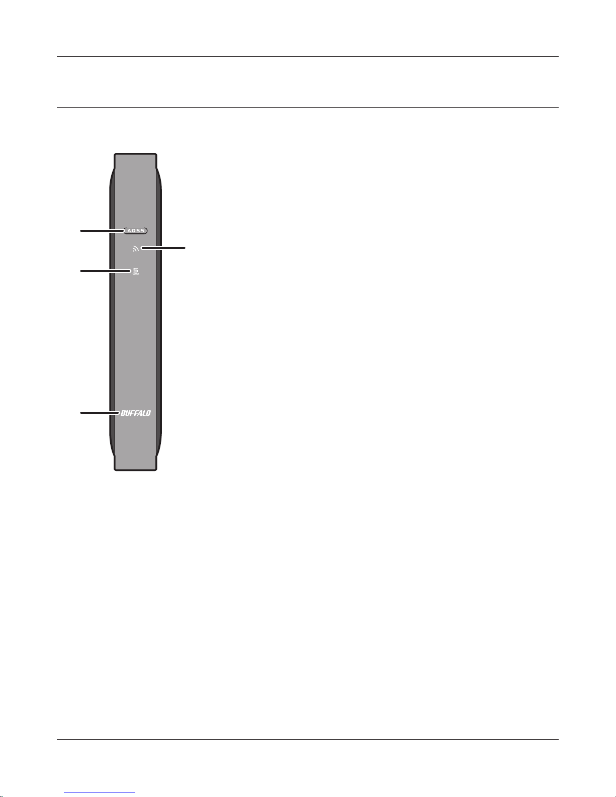
Front Panel LEDs
1
2
3
4
1
AOSS / WPS button To initiate AOSS/WPS, hold down this button until the Wireless LED
ashes (about 1 second). Then, push the AOSS or WPS button on your
wireless access point to complete the connection. Both devices must be
powered on for this to work.
2
Wireless LED (Blue or Amber)
On: Wireless LAN is enabled.
Blinking: Wireless LAN is transmitting.
2 blinks: AirStation is waiting for an AOSS or WPS security key.
Continuously
blinking:
O: Wireless LAN is disabled.
Note:
Wireless LED is blue : Security settings have been made for the wireless LAN.
Wireless LED is amber : Security settings have not been made for the wireless LAN.
AOSS/WPS error; failed to exchange security keys.
- 5 -
Page 7

Chapter 1 Product Overview
3
5 GHz Fixed mode LED (Blue)
On: Operating in 5 GHz band xed mode.
O: 5 GHz band xed mode is o.
4
Bualo LED (White or Red)
On (White): Power is on.
O: Power is o.
On (Red)*1: Booting.
2 blinks (Red)*2: Flash ROM error.
3 blinks (Red)*2: Wired Ethernet LAN error.
4 blinks (Red)*2: Wireless LAN error.
9 blinks (Red)*2: System error.
Continuously
Updating rmware, saving settings, or initializing settings.
blinking*1:
*1 Never unplug the AC adapter while the Bualo LED is blinking continuously.
*2 Turn o AirStation rst, wait for a few seconds, then turn it back on.
- 6 -
Page 8
Chapter 1 Product Overview
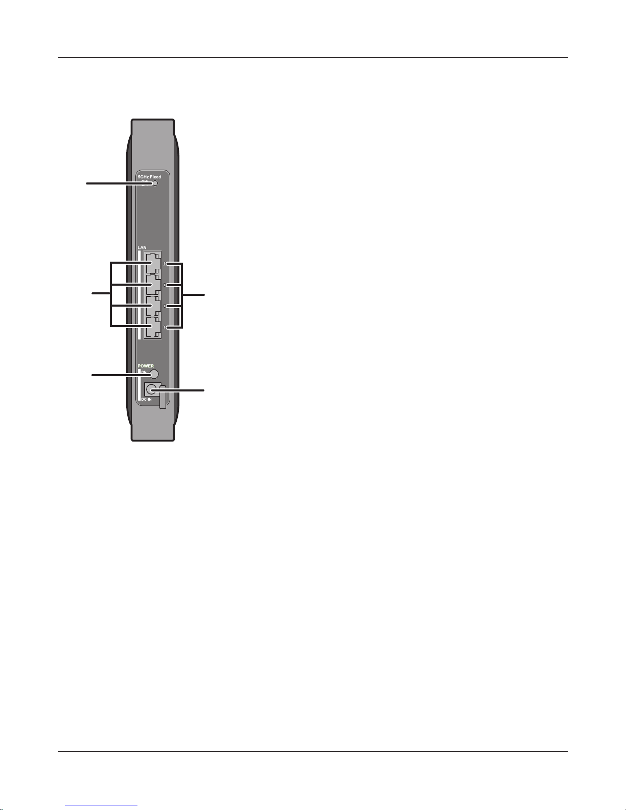
Back Panel
5
6
7
8
9
5
5 GHz Fixed Mode
button
6
LAN Port Connect your computer, hub, or other Ethernet devices to these ports.
7
LAN LED (Green)
This button is used to enable or disable 5 GHz xed mode. The operation
mode is switched by pressing the button until the 5 GHz xed mode LED
turns on or o (about 1 second).
This switching hub supports 10 Mbps,100 Mbps, and 1000 Mbps
connections.
On: An Ethernet device is connected.
Blinking: An Ethernet device is communicating.
8
Power button This button turns the power on and o.
9
DC Connector Connect the included AC adapter here.
- 7 -
Page 9

Chapter 1 Product Overview
Bottom
10
10
Reset button To reset all settings, hold down this button until the Bualo LED turns red
(about 3 seconds). The power must be on for this to work.
Right Side
11
11
Mounting holes Mounting holes are provided for mounting the AirStation to a
wall. Use the supplied screws in the holes to mount to a wall.
- 8 -
Page 10
Chapter 1 Product Overview
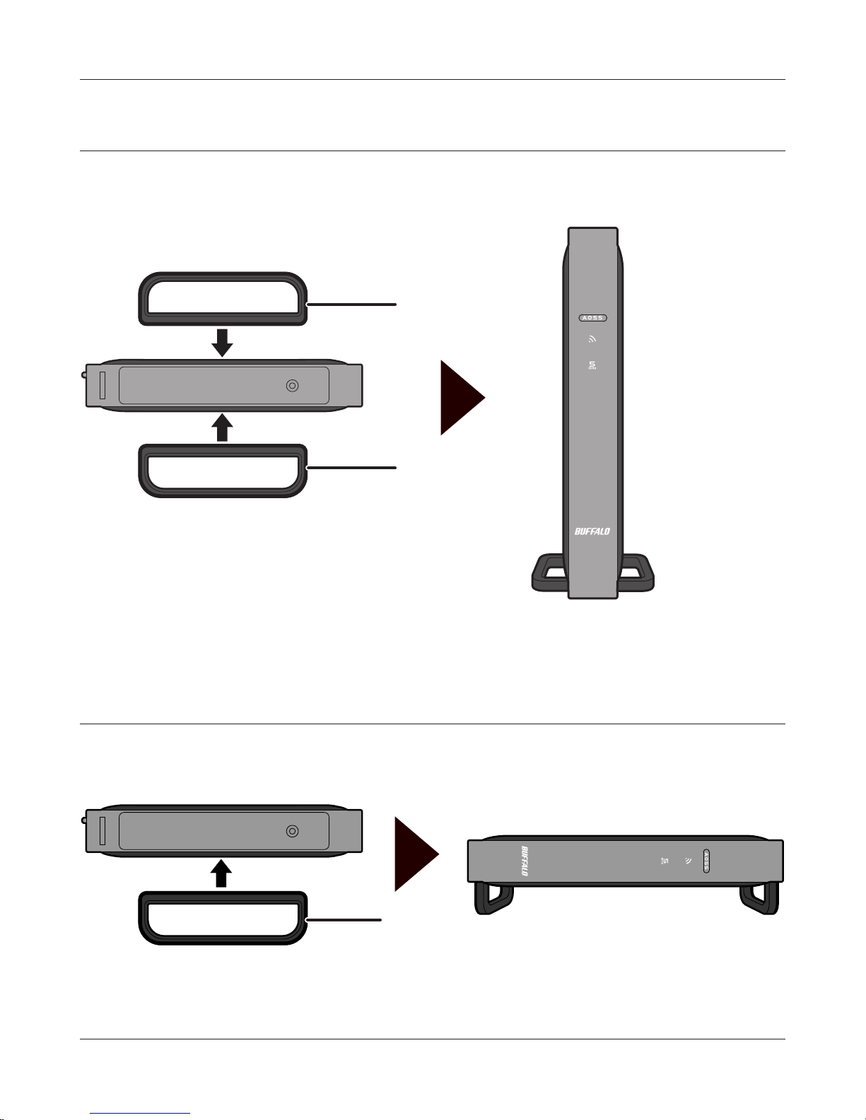
Vertical Placement
Attach the stand as shown in the gure below.
Stand
Stand
Horizontal Placement
The same stand also allows horizontal placement. Install the stand as shown in the gure below.
Stand
- 9 -
Page 11
Chapter 1 Product Overview
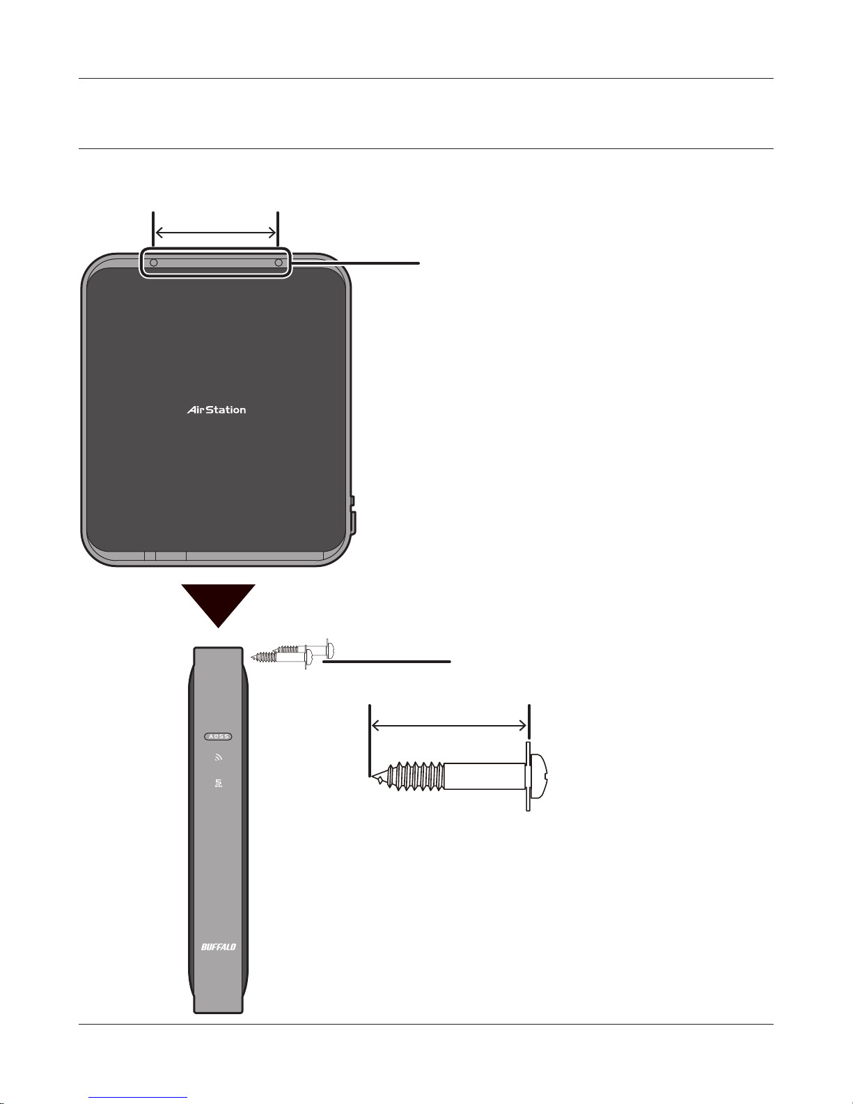
Wall-Mounting
Install with the supplied screws in the mounting holes of the AirStation as shown in the gure
below.
85 mm (3.35 in.)
Mounting holes
Screws
50 mm (1.97 in.)
- 10 -
Page 12
Chapter 2 - Installation
Initial Setup (one-touch connection)
To congure your AirStation, follow the procedure below.
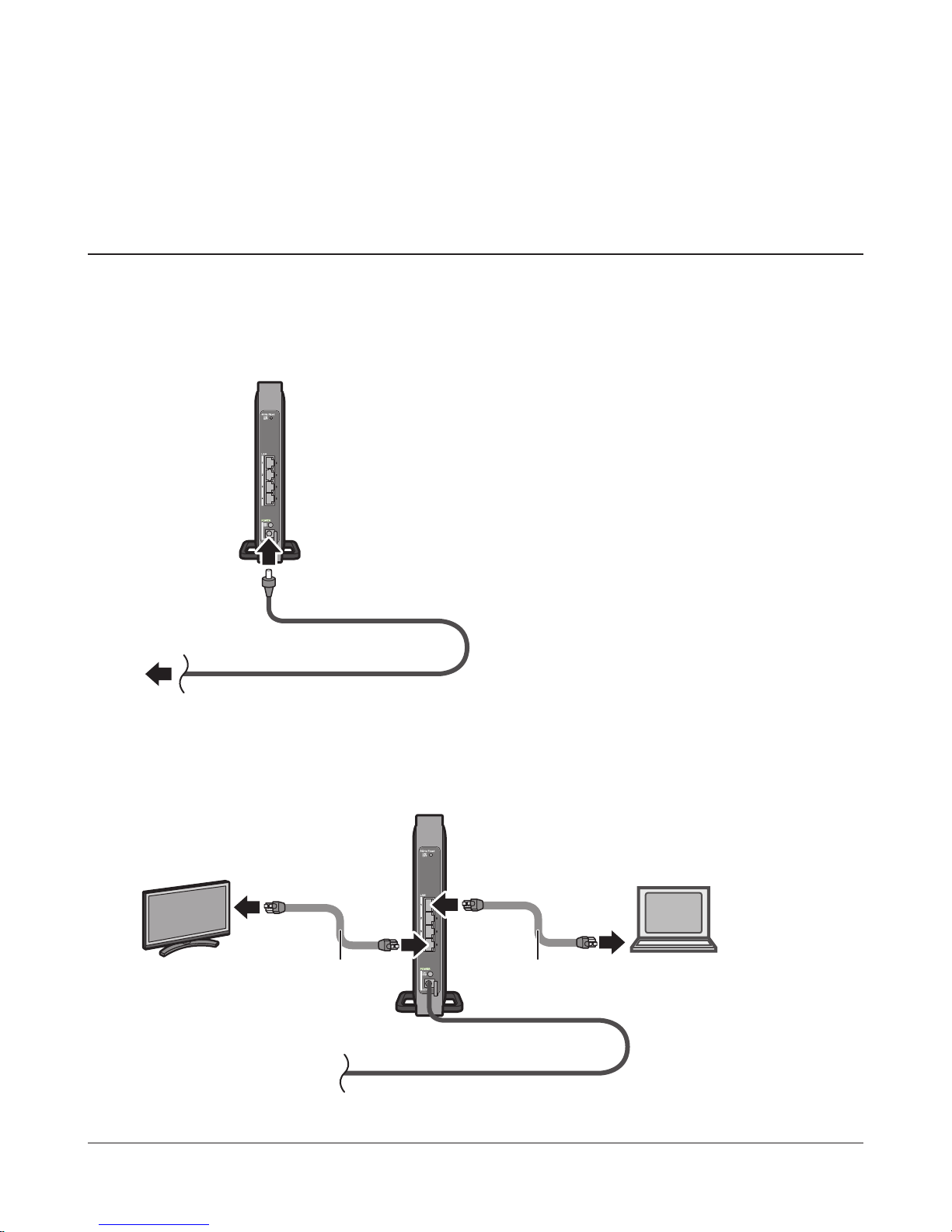
1
2
Turn on the AirStation, then wait one minute.
AirStation
Note : If the power does not turn on even when the AC
adapter is connected, press the Power button on
1) Connect the power supply
power outlet
the rear of the AirStation.
Use a LAN cable to connect the LAN port on the AirStation to your computer, television, or
other client device.
2) connect
TV
LAN cable
1) connect
AirStation
1) connect
- 11 -
LAN cable
2) connect
computer
Page 13

Chapter 2 Installation
3
4
5
6
Once your computer has booted, the AirStation’s LEDs should be lit as described below:
Wireless On or blinking.
5 GHz On or o.
Bualo White light on.
LAN Green light on or blinking.
For LED locations, refer to chapter 1.
Press the WPS (or AOSS) button of the wireless router that you are currently using.
Note : This example explains how to make a one-touch connection between the AirStation and your wireless
router. To make the setting from the conguration interface of the AirStation, see Chapter 3.
Press the AOSS/WPS button on the AirStation until the wireless LED button on the front panel
starts ashing (about 1 second).
After about one minute, check that the Wireless LED on the AirStation’s front panel is lit.
Note : If the Wireless LED continues ashing, connection with the wireless router has failed. Perform the
procedure again from Step 4.
7
Launch your web browser. If you can connect to the Internet, then setup is completed.
Note : If you cannot connect to the Internet, there may be a problem with the settings of your wireless router.
Refer to the manual for your wireless router for help conguring it.
- 12 -
Page 14

Chapter 2 Installation
Manual Setup
1
2
3
4
5
Refer to Chapter 3 to open the conguration interface for the AirStation.
Click [Connect to AirStation (master)].
Click [Search].
Choose your wireless router and click [Select].
Enter the encryption type and encryption key. Click [Setup].
Note : If you cannot connect to the wireless router, double-check your encryption type and key. These settings
must be the same for both the wireless router and the wireless bridge.
- 13 -
Page 15
Chapter 3 - Conguration
The web-based conguration tool lets you change the AirStation’s settings. Don’t change these
settings unless you know what you’re doing.
Installing the Ethernet Converter Manager
(Windows)
The Ethernet Converter Manager is required to display the AirStation conguration interface for a
Windows computer. Use the procedure below to perform the installation.
1
2
3
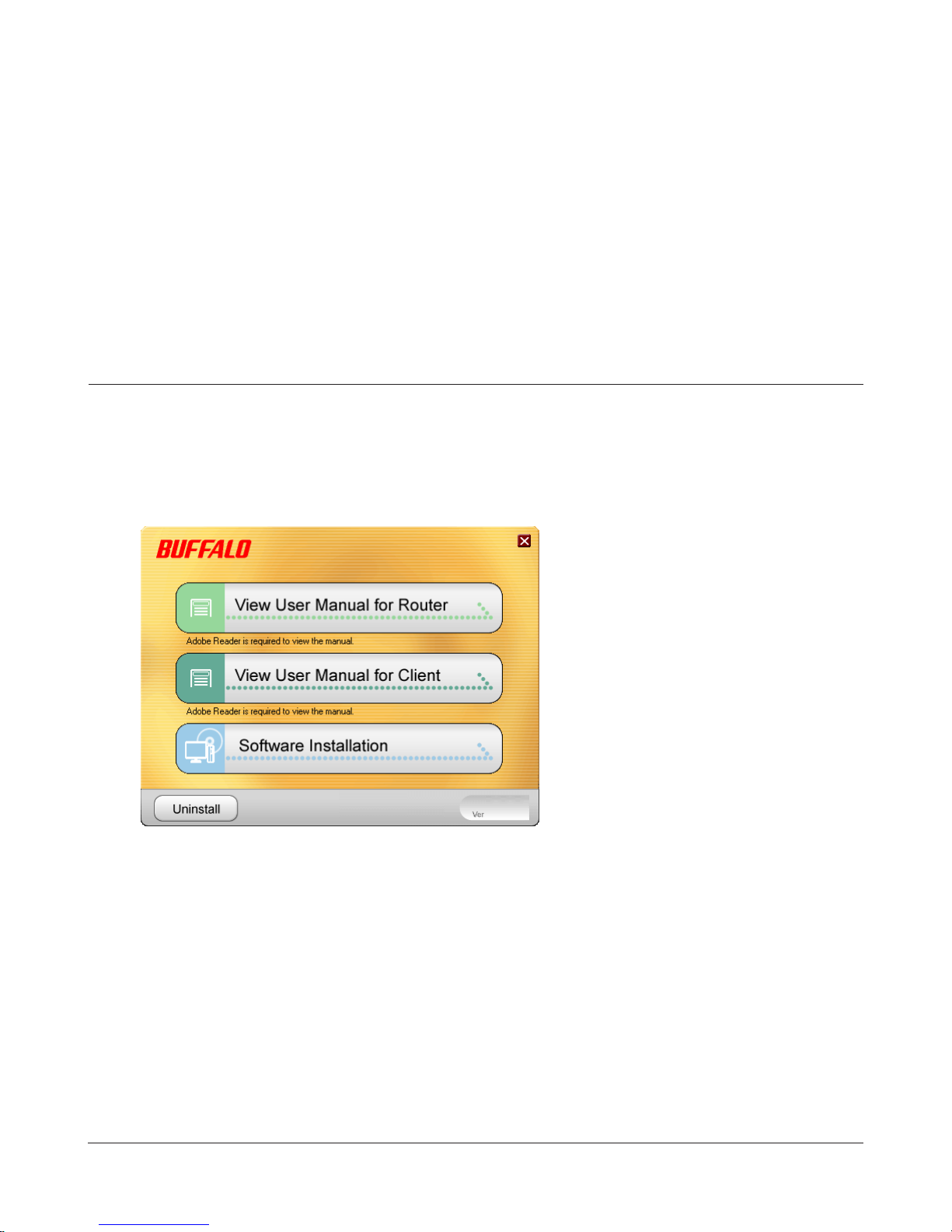
Load the AirNavigator CD into your computer.
Click [Software installation].
Step through the wizard to install the Ethernet Converter Manager software.
- 14 -
Page 16
Chapter 3 Conguration
Setting the AirStation IP Address (Windows)
The Ethernet Converter Manager can be used to change the IP address of the AirStation. If using a
Windows computer, follow the procedure below to set the AirStation’s IP address.
1
2
3
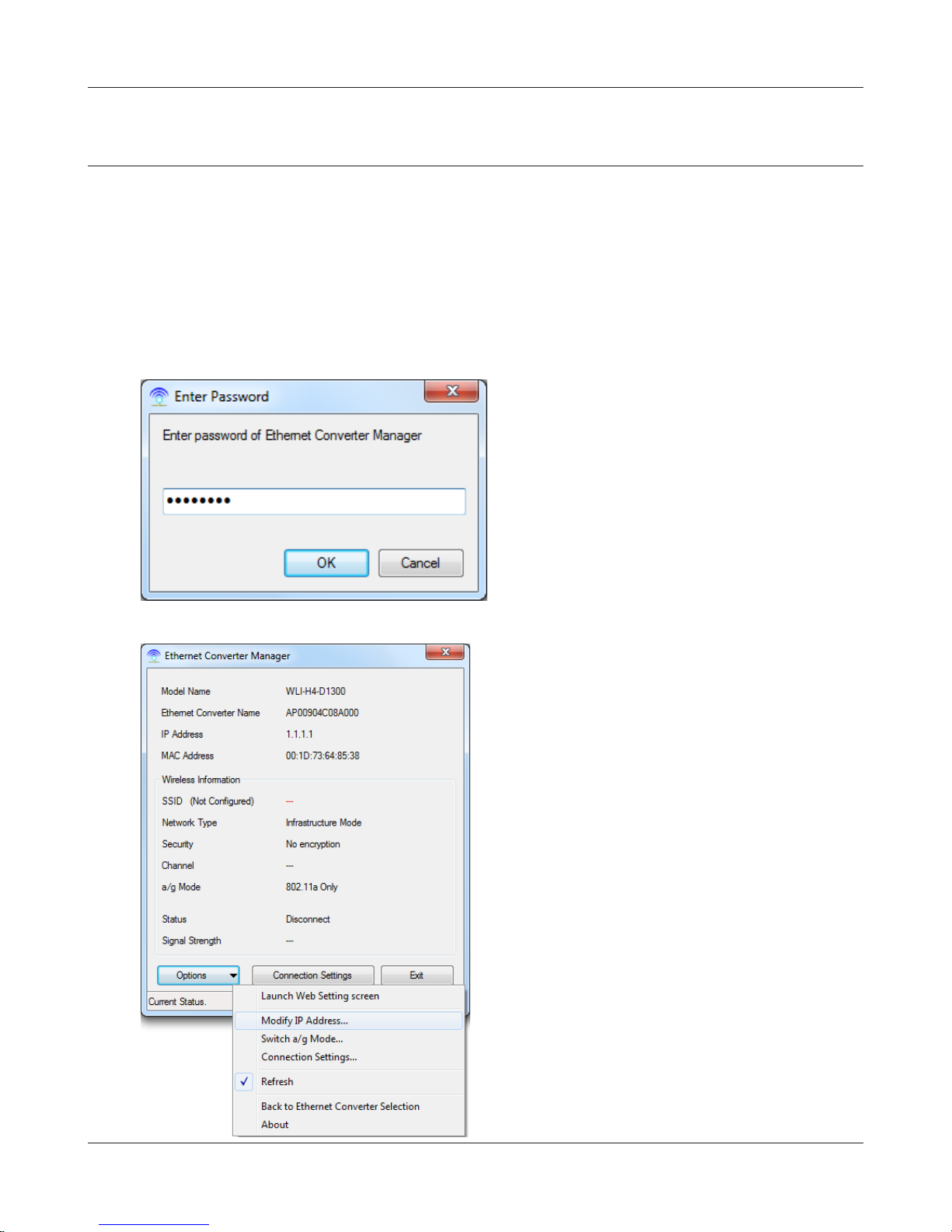
Click [Start] > [All programs] > [BUFFALO] > [AirStation Utility] > [Ethernet Converter
Manager].
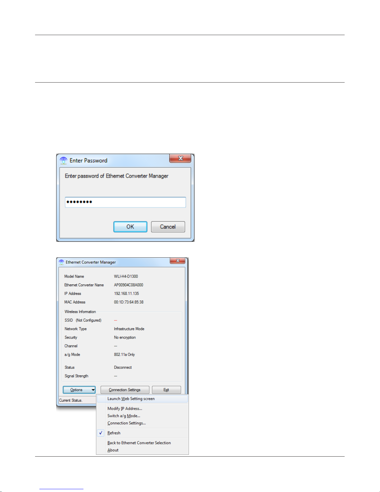
When this screen appears, enter the
password, then click [OK].
Notes: · By default, the password is “password”.
· If you forget your password, hold down
the reset button (page 8) to initialize all
settings. The password will then revert to
“password”. Note that all other settings
will also revert to their default values.
Click [Options] > [Modify IP Address...].
- 15 -
Page 17
Chapter 3 Conguration
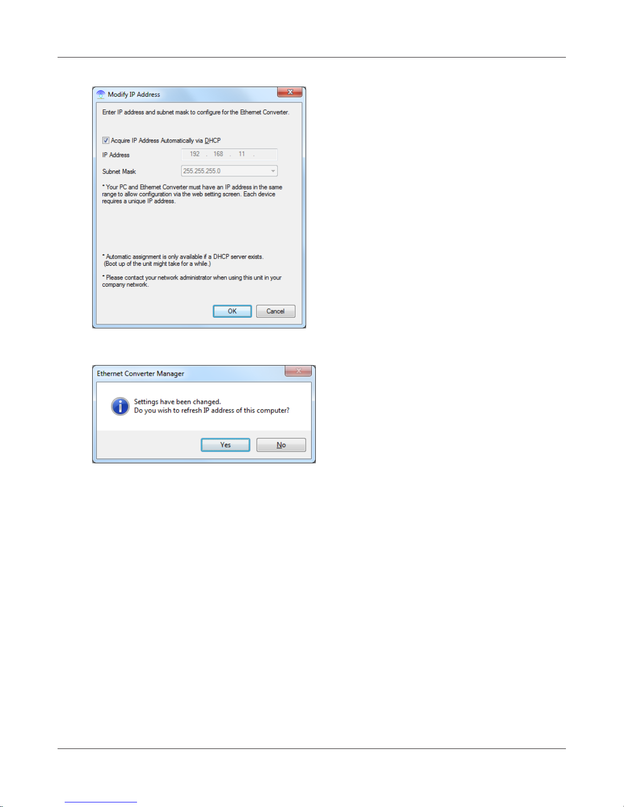
4
5
Select “Acquire IP Address Automatically via
DHCP”, then click [OK].
Click [Yes].
- 16 -
Page 18
Chapter 3 Conguration
Accessing the Web-based Conguration Interface
(Windows)
To manually set the AirStation advanced settings from a Windows computer, use the procedure
below to log into the AirStation Conguration interface.
1
2
3
Click [Start] > [All programs] > [BUFFALO] > [AirStation Utility] > [Ethernet Converter
Manager].
When this screen appears, enter the
password, then click [OK].
Notes: · By default, the password is “password”.
· If you forget your password, hold down
the reset button (page 8) to initialize all
settings. The password will then revert to
“password”. Note that all other settings
will also revert to their default values.
Click [Options] > [Launch Web Setting
screen].
- 17 -
Page 19
Chapter 3 Conguration
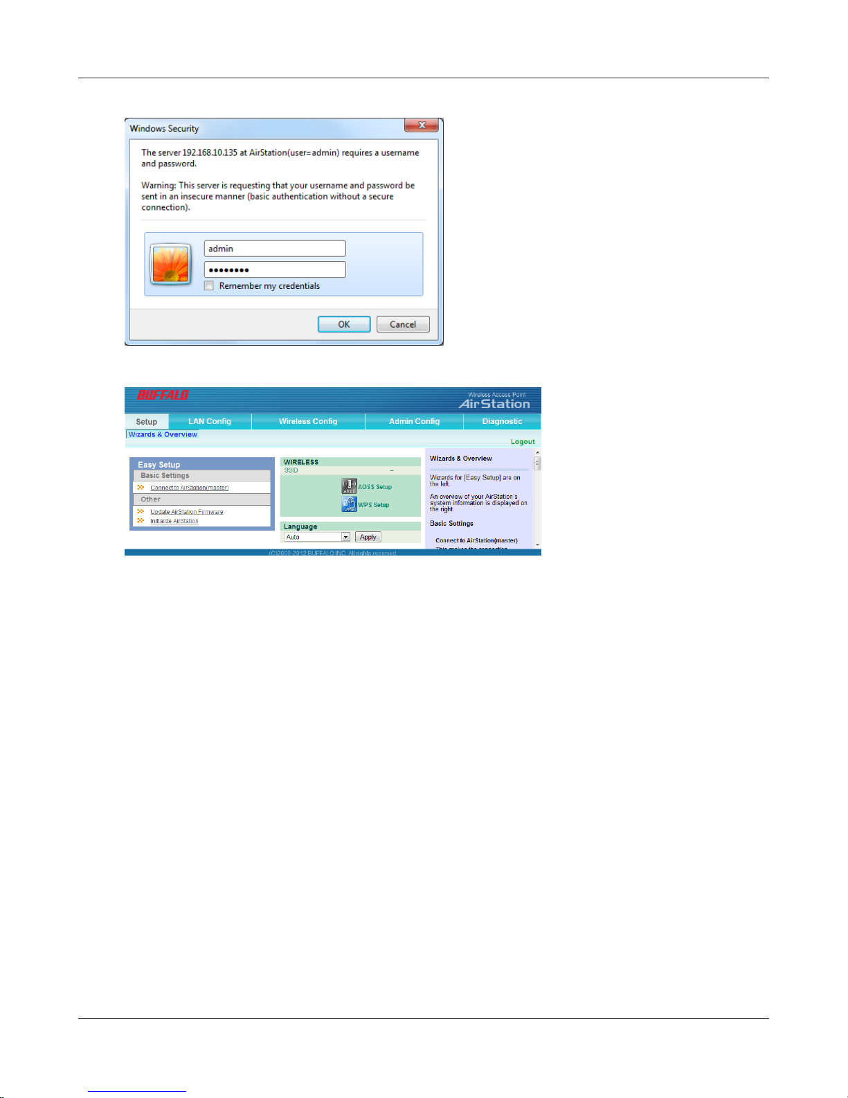
4
5
Enter "admin" for the username and
"password" for the password, then click
[OK].
Note: If the password was changed, enter the
new password instead of the default.
This is the conguration
interface, where most wireless
media bridge settings can be
congured.
- 18 -
Page 20

Chapter 3 Conguration
Accessing the Web-based Conguration Interface
(Mac OS X)
To access the conguration interface of the AirStation from a Mac, the IP address of the AirStation
is required. If you do not know the IP address, use the procedure below to access the conguration
interface.
Note: If you do not know the IP address of the AirStation, reset the AirStation. All settings will be changed to their
default values.
1
2
3
4
5
6
Click [Apple menu] > [System Preferences…].
Click [Network].
Click [Ethernet].
Select [Manually] in the Congure IPv4 eld.
Note: Make a note of the current IP address.
Set the IP address of the Mac to be on the same subnet as the AirStation.
The rst three numbers in the IP address should be the same and the fourth dierent. For
example, if the IP address of the AirStation is 1.1.1.1, you could set the IP address of the Mac
to 1.1.1.2. Click [Apply].
Launch your web browser, enter the IP address of the AirStation in the address eld, and
press the Enter key.
When a screen appears for entering the name and password, enter "admin" in the username
eld and "password" in the password eld, then click [OK].
7
When the settings for the AirStation are complete, return the IP address of the Mac to its
original setting that was noted in step 4.
- 19 -
Page 21

Chapter 3 Conguration
Conguration Interface Menus
The following settings may be changed from the conguration interface. Please refer to the pages
listed at right for explanations of each item.
Main screen Descriptions Page
LAN Cong
LAN Congure the AirStation’s IP address. Page 22
Wireless Cong
WPS WPS Status and Settings. Page 23
AOSS AOSS Status and Settings. Page 24
Basic Congure basic wireless settings. Page 25
Advanced Congure advanced wireless settings. Page 27
WMM Set priorities for Wireless Multimedia Extensions (Wi-Fi Multimedia). Page 28
Admin Cong
Name Congure the AirStation’s name. Page 30
Password Congure the AirStation’s login password for access to the
conguration interface.
Time / Date Congure the AirStation’s internal clock. Page 32
NTP Congure the AirStation to synchronize with an NTP server to
automatically set the AirStation’s internal clock.
Access Congure access restrictions to the AirStation’s conguration screens. Page 34
Log Congure a syslog server to manage the AirStation’s logs. Page 35
Save / Restore Save or restore the AirStation’s conguration from a conguration le. Page 36
Initialize / Restart Initialize the AirStation or reboot it. Page 37
Update Update the AirStation’s rmware. Page 38
Diagnostic
System Info View current system information for the AirStation. Page 39
Logs Check the AirStation’s logs. Page 40
Packet Info View all packets transferred by the AirStation. Page 41
Client Monitor View all devices currently connected to the AirStation. Page 42
Page 31
Page 33
Ping Test the AirStation’s connection to other devices on the network. Page 43
Logout
Click this to log out of the AirStation’s conguration interface.
- 20 -
Page 22

Chapter 3 Conguration
Setup
Setup is the home page of the conguration interface. You can verify settings and the status of the
AirStation here.
Parameter Meaning
LAN Cong Displays the conguration screen for the LAN ports.
Wireless Cong Click this button to display the conguration screen for wireless
settings.
Admin Cong Click this button to display the conguration screen for
administration settings.
Diagnostic Click this button to display the status of the AirStation.
Easy Setup Enables you to easily congure the AirStation’s network settings
automatically.
WIRELESS Displays the current wireless settings.
AOSS Setup Click this button to display the AOSS conguration screen.
WPS Setup Click this button to display the WPS conguration screen.
Language Enables you to select the language you use.
Logout Log out of the conguration interface. If the AirStation does not
communicate for 5 minutes, it will log out automatically.
- 21 -
Page 23

Chapter 3 Conguration
LAN Cong
LAN
Congure LAN-side settings.
Parameter Meaning
LAN Side IP Address By default, the LAN side IP address is 1.1.1.1 with subnet mask
255.255.255.0. You may change it here.
Default Gateway Set the default gateway IP address.
DNS Server Address Set the DNS server IP address.
- 22 -
Page 24

Chapter 3 Conguration
Wireless Cong
WPS
WPS Status and Settings.
Parameter Meaning
WPS Enable to use WPS automatic conguration.
PIN cord method This uses the WPS PIN code system to obtain wireless security
Push button method This uses the WPS Push Button method to obtain wireless security
List of wireless connections (WPS) Displays the wireless security information of the wireless
Initiates WPS automatic wireless conguration. Click this, then press
or click the WPS button on your WPS-compatible wireless router.
information from the wireless access point.
information from the wireless access point.
connection where the WPS function was used to set security.
- 23 -
Page 25

Chapter 3 Conguration
AOSS
AOSS Status and Settings.
Parameter Meaning
Initiates AOSS automatic wireless conguration. Click this, then
press or click the AOSS button on your AOSS-compatible wireless
router.
Click this button to disconnect AOSS connections.
Encryption Type Displays the Security Level setting for AOSS.
AOSS Button on the AirStation Unit Uncheck to disable the physical AOSS button on the AirStation.
AOSS Client Information Displays AOSS clients connected to the AirStation and information
of the devices which are wirelessly communicated.
- 24 -
Page 26

Chapter 3 Conguration
Basic
Congure basic wireless settings from here.
Parameter Meaning
SSID The SSID may contain 1 - 32 alphanumeric characters.
Wireless authentication Species the authentication method used when connecting to a
wireless router.
Encryption for wireless You may use any of the following types of encryption:
Not encrypted
Data is transmitted without encryption. With this setting, anyone
within range can connect to your wireless network and might
be able to access data on the network. Not recommended for
anyone with private data that needs to be kept secure. [Not
encrypted] can be selected only when [Do not authenticate] is
selected for wireless authentication.
WEP
WEP is a common encryption method supported by most
devices. WEP can only be selected when wireless authentication
is set to [Do not authenticate]. Note that WEP’s encryption is
weak, and networks protected with WEP are not much more
secure than those with no encryption at all. Not recommended
for anyone with private data that needs to be kept secure.
TKIP
TKIP is an encryption method which is more secure than WEP, but
slower. Use an pre-shared key to communicate with a wireless
device.
TKIP can be selected only when WPA-PSK or WPA2-PSK is selected
for wireless authentication.
- 25 -
Page 27

Chapter 3 Conguration
Parameter Meaning
AES
AES is more secure than WEP, and faster. Use a pre-shared key to
communicate with a wireless device.
AES can be selected only when WPA-PSK or WPA2-PSK is selected
for wireless authentication.
WPA-PSK (Pre-Shared Key) A pre-shared key or passphrase is the password for your wireless
connections. There are two dierent formats for a pre-shared
key. Use 8 to 63 alphanumeric characters (case-sensitive) for an ASCII
passphrase, or use 64 alphanumeric characters (0 to 9 and a to f, not casesensitive) for a hexadecimal passphrase.
WEP encryption key setting A WEP encryption key (passphrase) may have any of four dierent
formats. An ASCII passphrase may use either 5 or 13 alphanumeric
characters (case-sensitive). A hexadecimal passphrase may use either 10
or 26 alphanumeric characters (0 to 9 and a to f, not case-sensitive).
11a/11g selection This species the band used when connecting with the wireless
access router.
Automatic (11a priority)
First, a connection is tried at 802.11a, and if a connection cannot
be made, a connection is tried at 802.11g.
Automatic (11g priority)
First, a connection is tried at 802.11g, and if a connection cannot
be made, a connection is tried at 802.11a.
11a only
Only 802.11a connections are allowed. Even if an 802.11a
connection cannot be made, 802.11g is not used.
11g only
Only 802.11g connections are allowed. Even if an 802.11g
connection cannot be made, 802.11a is not used.
- 26 -
Page 28

Chapter 3 Conguration
Advanced
Congure advanced wireless settings.
Parameter Meaning
MAC Address for wireless
communication
802.11n protection Enable to use 802.11n protection. 802.11n protection gives priority
Output Power This sets the output of the wireless signal. Because the wireless
Request of multicast translation Specic multicast data (such as video broadcast data) can be
Select which MAC address is used for wireless communication.
to 802.11n devices in mixed mode (11b/g or 11a) networks.
transmission output and signal distance range are nearly
proportional, when the wireless transmission output is reduced,
the signal distance range also becomes shorter.
transferred at high speeds to an access point that supports the
multicast control.
- 27 -
Page 29

Chapter 3 Conguration
WMM
Set priorities for specic communications.
- 28 -
Page 30

Chapter 3 Conguration
Parameter Meaning
WMM-EDCA Parameters You don't usually need to change these settings. Using the default
settings is recommended.
Priority
The following priorities may be applied to individual
transmission packets: (Highest) 8, (High) 4, (Normal) 2, and
(Low) 1. From the queue, these packets are processed in order of
priority.
CWmin, CWmax
The maximum and minimum value of the contention window.
The contention window is used in the frame collision avoidance
structure performed in IEEE802.11, and generally, the smaller the
value in the window, the higher the probability that the queue
obtains the right to send.
AIFSN
The interval to send frames. The unit of the AIFSN is a slot, just as
the window dened by CWmin and CWmax is. The smaller the
interval of sending frames, the faster the algorithm can restart.
As a result, the priority of the queue is higher.
TXOP Limit
The period of time that the queue can use after obtaining the
right to send. The unit is 32 ms. The longer this time, the more
frames can be sent per right to send. However, the queue may
interfere with other packet transmissions. If TXOP Limit is set to 0
(zero), only one frame can be sent per right to send.
Admission Control
Restricts new frames from interfering with a previous queue. New
packets are prioritized lower until a queue of them is collected. As
the new queue accumulates more packets, its priority increases.
- 29 -
Page 31

Chapter 3 Conguration
Admin Cong
Name
Congure basic AirStation settings.
Parameter Meaning
AirStation Name Enter a name for the AirStation. Names may include up to 64
alphanumeric characters and hyphens (-).
- 30 -
Page 32

Chapter 3 Conguration
Password
Congure the password to log in to the AirStation’s conguration interface.
Parameter Meaning
Administrator Name The name of the Administrator account is “admin”.
Administrator Password The Administrator password may contain up to 8 alphanumeric
characters and underscores (_).
- 31 -
Page 33

Chapter 3 Conguration
Time/Date
Congure the AirStation’s internal clock.
Parameter Meaning
Local Date You may manually set the date of the AirStation’s internal clock.
Local Time You may manually set the time of the AirStation’s internal clock.
Time Zone Specify the time zone (oset of Greenwich Mean Time) of the
AirStation's internal clock.
DST (Daylight Saving Time) You may congure the AirStation to automatically use DST
(Daylight Saving Time). If selected, the AirStation will automatically
adjust the time at the beginning and end of DST.
- 32 -
Page 34

Chapter 3 Conguration
NTP
Congure an NTP server to automatically synchronize the AirStation’s internal clock.
Parameter Meaning
NTP Functionality Enable to use an NTP server. The default is Enabled.
NTP Server Enter the name of the NTP server as a hostname, hostname with
domain name, or IP address. Up to 255 alphanumeric characters
and hyphens (-) may be used. The default is “time.nist.gov”.
Update Interval How often will the AirStation check the NTP server for the correct
time? Intervals of 1 - 24 hours may be set. The default is 24 hours.
- 33 -
Page 35

Chapter 3 Conguration
Access
Restrict access to the AirStation’s conguration interface.
Parameter Meaning
Log Output Enabling outputs a log of changes to access settings.
Prohibit conguration from wireless
LAN
Prohibit conguration from wired
LAN
If enabled, prevents access to conguration interface from
wirelessly connected devices (only wired devices may congure).
If enabled, prevents access to conguration interface from wired
devices (only wirelessly connected devices may congure).
- 34 -
Page 36

Chapter 3 Conguration
Log
Transfer the AirStation’s logs to a syslog server.
Parameter Meaning
Log Transfer Enable to send logs to a syslog server.
Syslog Server Identify the syslog server by hostname, hostname with domain
name, or IP address. You may enter up to 255 alphanumeric
characters and hyphens (-).
Logs Choose which logs will be transferred to the syslog server.
- 35 -
Page 37

Chapter 3 Conguration
Save/Restore
Save AirStation settings as a le and restore from them later.
Parameter Meaning
Save current settings Clicking [Save] will save the current conguration of the AirStation
to a le. If the [Encrypt the conguration le with a password]
option is checked, then the conguration le will be password
protected with the password.
Restore Conguration from Backup
File
Restore the conguration of the AirStation from a saved
conguration le by clicking the [Browse...], navigating to the
conguration le, and then clicking [Restore]. If the conguration
le was password protected, then put a check next to [Enter
password], enter the password, and click [Restore].
- 36 -
Page 38

Chapter 3 Conguration
Initialize/Restart
Initialize or restart the AirStation.
Parameter Meaning
Restart Click [Restart Now] to restart the AirStation.
Initialize Click [Initialize Now] to initialize and restart the AirStation.
- 37 -
Page 39

Chapter 3 Conguration
Update
Update the AirStation’s rmware.
Parameter Meaning
Firmware Version Displays the current rmware version of the AirStation.
Update Method Specify Local File
Updates from a rmware le stored on your computer.
Auto Update Online
Automatically updates to the latest rmware available.
Firmware File Name Click [Browse...] to navigate to the rmware le on your computer
if [Specify Local File] was selected. You don’t need to specify the
rmware location if you’re using [Automatic Update]. Click [Update
Firmware] to update the rmware.
Firmware update Reminder Specify Enable/Disable Firmware Update Reminder.
Remind Time Specify the time when the system detects new rmware.
- 38 -
Page 40

Chapter 3 Conguration
Diagnostic
System Info
View system information for the AirStation.
Parameter Meaning
Model Displays the product name of the AirStation and the rmware
AirStation Name Displays the name of the AirStation.
LAN Displays information about the LAN port.
Wireless Displays the wireless status.
version.
- 39 -
Page 41

Chapter 3 Conguration
Logs
The AirStation’s logs are recorded here.
Parameter Meaning
Display log info Choose the types of logs to display.
Logs Displays the log information recorded in the AirStation.
- 40 -
Page 42

Chapter 3 Conguration
Packet Info
View packet transfer information.
Parameter Meaning
Sent Displays the number of packets sent to the wired LAN and the
wireless LAN.
Received Displays the number of packets received from the wired LAN and
the wireless LAN.
- 41 -
Page 43

Chapter 3 Conguration
Client Monitor
This screen shows devices that are connected to the AirStation.
Parameter Meaning
Client Monitor Displays information (MAC address, communication method,
wireless authentication and 802.11n) for devices that are
connected to the AirStation.
- 42 -
Page 44

Chapter 3 Conguration
Ping
A ping test checks whether the AirStation can communicate with a specic network device.
Parameter Meaning
Destination Address Enter the IP address or hostname of the device that you are testing
communication with, then click [Execute]. The result will be
displayed below.
- 43 -
Page 45

Chapter 4 - TroubleShooting
When connection to a wireless router is not possible
• Turn the power for the wireless router o and then on again.
• If the “5 GHz xed mode” is enabled, turn it o.
• Refer to Chapter 2 to connect this unit to a wireless router.
• Move this unit closer to the wireless router.
• Make sure that your client devices are congured to “obtain an IP address automatically from
DHCP”.
• Verify that your web browser is not set to use proxies.
• Restart your wireless router and AirStation.
You forgot the SSID, encryption key, or password
for the wireless network.
• Ask your network administrator about your SSID and encryption settings. These settings must
match the SSID and encryption settings of the wireless router.
• If your wireless router supports AOSS or WPS, try using them to connect to the wireless router.
Instructions for connecting with AOSS or WPS are in page 12.
Restoring the Default Conguration
With the AirStation powered on, hold down this button
for 3 seconds to return it to factory default settings.
- 44 -
Page 46

Chapter 4 TroubleShooting
TCP/IP Settings (Windows 7)
To congure TCP/IP in Windows 7, follow the procedure below.
1
2
3
4
5
6
7
Click [Start] > [Control Panel] > [Network and Internet].
Click [Network and Sharing Center].
Click [Change Adapter Settings] on the left side menu.
Right-click on [Local Area Connection], then click [Properties].
If the User Account Control screen opens, click [Yes] or [Continue].
Select [Internet Protocol Version 4 (TCP/IPv4)] then click [Properties].
To have DHCP set your IP address settings automatically, check [Obtain an IP address
automatically] and [Obtain DNS server address automatically].
To set your IP address settings manually, enter values for each setting. Examples:
8
If your AirStation’s IP address is 1.1.1.1,
IP address 1.1.1.2
Subnet mask 255.255.255.0
Default gateway blank
Preferred DNS server blank
Alternate DNS server blank
Click [OK].
- 45 -
Page 47

Chapter 4 TroubleShooting
TCP/IP Settings (Windows Vista)
To congure TCP/IP in Windows Vista, follow the procedure below.
1
2
3
4
5
6
7
Click [Start] > [Settings] > [Control Panel].
Click [Network and Sharing Center].
Click [Manage network connections] on the left side menu.
Right-click on [Local Area Connection], then click [Properties].
If the User Account Control screen opens, click [Yes] or [Continue].
Select [Internet Protocol Version 4 (TCP/IPv4)], then click [Properties].
To have DHCP set your IP address settings automatically, check [Obtain an IP address
automatically] and [Obtain DNS server address automatically].
To set your IP address settings manually, enter values for each settings. Example:
8
If your AirStation’s IP address is 1.1.1.1,
IP address 1.1.1.2
Subnet mask 255.255.255.0
Default gateway blank
Preferred DNS server blank
Alternate DNS server blank
Click [Close].
- 46 -
Page 48

Chapter 4 TroubleShooting
TCP/IP Settings (Windows XP)
To congure TCP/IP in Windows XP, follow the procedure below.
1
2
3
4
5
Click [Start] > [Settings] > [Control Panel].
Double-click [Network].
Right-click on [Local Area Connection], then click [Properties].
Select [Internet Protocol (TCP/IP)], then click [Properties].
To have DHCP set your IP address settings automatically, check [Obtain an IP address
automatically] and [Obtain DNS server address automatically].
To set your IP address settings manually, enter values for each setting. Examples:
If your AirStation’s IP address is 1.1.1.1,
IP address 1.1.1.2
Subnet mask 255.255.255.0
Default gateway blank
Preferred DNS server blank
Alternate DNS server blank
6
Click [Close].
- 47 -
Page 49

Chapter 4 TroubleShooting
TCP/IP Settings (Mac OS X)
To congure TCP/IP in Mac OS X, follow the procedure below.
1
2
3
4
Click [Apple menu] > [System Preferences…].
Click [Network].
Click [Ethernet].
To have DHCP set your IP address settings automatically, select [Using DHCP] in the Congure
IPv4 eld.
To set your IP address settings manually, select [Manually] in the Congure IPv4 eld and
enter values for each setting. Examples:
If your AirStation’s IP address is 1.1.1.1,
IP Address 1.1.1.2
Subnet Mask 255.255.255.0
Router blank
DNS Server blank
Search Domains blank
5
Click [Apply].
- 48 -
Page 50

Chapter 4 TroubleShooting
Other Tips
Issue:
I reset my AirStation to factory settings and forgot how to log in to the conguration interface.
Answer:
Open your browser, enter 1.1.1.1 as the browser address, and hit Enter. You will be prompted to log
in. Enter “admin” for the username and “password” for the password. Click [OK] to log in. The option
to reset your password will be available on the rst page.
Issue:
What can I do if my wireless connection drops randomly or seems slow?
Answer:
There are many environmental factors that may cause this. First, ensure the issue is not range
related by moving the wireless router and the client device closer together. If the connection drops
continue, then range is probably not the issue.
Other 2.4 GHz devices such as microwaves, other wireless networks, and 2.4 GHz wireless phones
may impact performance. Try a dierent wireless channel for your wireless router. Log in to the
wireless router with your browser. Click on the Wireless Cong tab and then the Basic tab. Wireless
channels from 1 - 11 may be selected. Try the Auto-Channel option if available. Otherwise, manually
select an alternate channel and click [Apply].
Issue:
Where can I download the latest drivers, rmware, and instructions for my Bualo wireless products?
Answer:
The latest drivers and rmware are available online at
www.bualotech.com
- 49 -
Page 51

Appendix
Specications
Wired LAN Interface
Standard Compliance IEEE802.3ab (1000BASE-T), IEEE802.3u (100BASE-TX), IEEE802.3 (10BASE-T)
Transmission Rate 10 / 100 / 1000 Mbps
Transmission Encoding 1000 BASE-T 4DPAM5, 100 BASE-TX 4B5B/MLT-3, 10 BASE-T Manchester Cording
Access Method CSMA/CD
Speed and Flow Control 10 / 100 / 1000 Mbps, Auto Sensing, Auto MDIX
Number of LAN Port 4
LAN Port Connector RJ-45
Wireless LAN Interface
Standard Compliance IEEE802.11ac (Draft 2.0) /n/a/g/b
Transmission Method Direct Sequence Spread Spectrum (DSSS), OFDM, MIMO
Transmission Rate
802.11ac (Draft)
802.11ac (Draft):
20 MHz BW (Long GI)
260, 234, 195, 175.5, 156, 117, 78, 58.5, 39, 19.5 Mbps (3 stream)
156, 130, 117, 104, 78, 52, 39, 26, 13 Mbps (2 stream)
78, 65, 58.5, 52, 39, 26, 19.5, 13, 6.5 Mbps (1 stream)
20 MHz BW (Short GI)
288.9, 260, 216.7, 195, 173.3, 130, 86.7, 65, 43.3, 21.7 Mbps (3 stream)
173.3, 144.4, 130, 115.6, 86.7, 57.8, 43.3, 28.9, 14.4 Mbps (2 stream)
86.7, 72.2, 65, 57.8, 43.3, 28.9, 21.7, 14.4, 7.2 Mbps (1 stream)
40 MHz BW (Long GI)
540, 486, 405, 364.5, 324, 243, 162, 121.5, 81, 40.5 Mbps (3 stream)
360, 324, 270, 243, 216, 162, 108, 81, 54, 27 Mbps (2 stream)
180, 162, 135, 121.5, 108, 81, 54, 40.5, 27, 13.5 Mbps (1 stream)
40 MHz BW (Short GI)
600, 540, 450, 405, 360, 270, 180, 135, 90, 45 Mbps (3 stream)
400, 360, 300, 270, 240, 180, 120, 90, 60, 30 Mbps (2 stream)
200, 180, 150, 135, 120, 90, 60, 45, 30, 15 Mbps (1 stream)
80 MHz BW (Long GI)
1170, 1053, 877.5, 702, 526.5, 351, 263.3, 175.5, 87.8 Mbps (3 stream)
780, 702, 585, 526.5, 468, 351, 234, 175.5, 117, 58.5 Mbps (2 stream)
390, 351, 292.5, 263.3, 234, 175.5, 117, 87.8, 58.5, 29.3 Mbps (1 stream)
80 MHz BW (Short GI)
1300, 1170, 975, 780, 585, 390, 292.5, 195, 97.5 Mbps (3 stream)
866.7, 780, 650, 585, 520, 390, 260, 195, 130, 65 Mbps (2 stream)
433.3, 390, 325, 292.5, 260, 195, 130, 97.5, 65, 32.5 Mbps (1 stream)
- 50 -
Page 52

Appendix
Transmission Rate
802.11n/a/b/g
802.11n:
20 MHz BW (Long GI)
195, 175.5, 156, 117, 78, 58.5, 39, 19.5 Mbps (3 stream)
130, 117, 104, 78, 52, 39, 26, 13 Mbps (2 stream)
65, 58.5, 52, 39, 26, 19.5, 13, 6.5 Mbps (1 stream)
20 MHz BW (Short GI)
216.7, 195, 173.3, 130, 86.7, 65, 43.3, 21.7 Mbps (3 stream)
144.4, 130, 115.6, 86.7, 57.8, 43.3, 28.9, 14.4 Mbps (2 stream)
72.2, 65, 57.8, 43.3, 28.9, 21.7, 14.4, 7.2 Mbps (1 stream)
40 MHz BW (Long GI)
405, 364.5, 324, 243, 162, 121.5, 81, 40.5 Mbps (3 stream)
270, 243, 216, 162, 108, 81, 54, 27 Mbps (2 stream)
135, 121.5, 108, 81, 54, 40.5, 27, 13.5 Mbps (1 stream)
40 MHz BW (Short GI)
450, 405, 360, 270, 180, 135, 90, 45 Mbps (3 stream)
300, 270, 240, 180, 120, 90, 60, 30 Mbps (2 stream)
150, 135, 120, 90, 60, 45, 30, 15 Mbps (1 stream)
802.11a/g:
54, 48, 36, 24, 18, 12, 9, 6 Mbps
802.11b:
11, 5.5, 2, 1 Mbps
Frequency Range Available frequencies depend on the country of purchase. See the next page
for details.
Access Mode Infrastructure Mode
Security AOSS, WPS, WPA2-PSK (TKIP/AES), WPA-PSK (TKIP/AES), 128/64bit WEP
Other
Power Supply External AC 100 - 240 V Universal, 50/60 Hz
Power Consumption About 9.8 W (Max)
Dimensions 212.2 x 183.2 x 34 mm (8.4 x 7.2 x 1.3 in.)
Weight 500 g (17.6 oz.)
Operating Environment 0 - 40° C (32 - 104° F) , 20 - 80 % (non-condensing)
- 51 -
Page 53

Appendix
802.11a Frequency Range
USA
Canada
802.11g Frequency Range
USA
Canada
5180-5240 MHz (Channels 36, 40, 44, 48)
5745-5825 MHz (Channels 149, 153, 157, 161, 165)
2412-2462 MHz (Channels 1, 2, 3, 4, 5, 6, 7, 8, 9, 10, 11)
- 52 -
Page 54

Appendix
Default Conguration Settings
Feature Parameter Default Setting
LAN LAN Side IP Address Manual Setup
1.1.1.1 (255.255.255.0)
Default Gateway none
DNS Server Address none
WPS WPS Enabled
List of wireless connections (WPS) none
AOSS Encryption Type none
AOSS Button on the AirStation
Unit
Basic SSID none
Wireless Authentication Do not authenticate
Encryption for wireless Not encrypted
11a/11g selection 11a only
Advanced MAC Address for wireless
communication
802.11n protection Disabled
Output Power 100%
Request of multicast translation Enabled
Enabled
Unit Address
- 53 -
Page 55

Appendix
Feature Parameter Default Setting
WMM WMM-EDCA Parameters
(Priority AC_BK (Low) )
WMM-EDCA Parameters
(Priority AC_BE (Normal) )
WMM-EDCA Parameters
(Priority AC_VI (High) )
For AP For STA
CWmin 15 15
CWmax 1023 1023
AIFSN 7 7
TXOP Limit 0 0
Admission Control ----- Disabled
For AP For STA
CWmin 15 15
CWmax 63 1023
AIFSN 3 3
TXOP Limit 0 0
Admission Control ----- Disabled
For AP For STA
CWmin 7 7
CWmax 15 15
AIFSN 1 2
TXOP Limit 94 94
Admission Control ----- Disabled
WMM-EDCA Parameters
(Priority AC_VO (Highest) )
CWmin 3 3
For AP For STA
CWmax 7 7
AIFSN 1 2
TXOP Limit 47 47
Admission Control ----- Disabled
Name AirStation Name AP + AirStation's MAC Address
Password Administrator Name admin (xed)
Administrator Password password
Time/Date Local Date 2012 Year 1 Month 1 Day
Local Time 0 Hour 0 Minute 0 Seconds
Time Zone
DST (Daylight Saving Time)
(GMT-06:00) Central Standard Time: CST
USA (From Second Sunday in Mar to rst Sunday in
Nov)
NTP NTP Functionality Enabled
NTP Server time.nist.gov
Update Interval 24 hours
- 54 -
Page 56

Appendix
Feature Parameter Default Setting
Access Log Output Disabled
Limitation Item Prohibit conguration from wireless LAN Disabled
Prohibit conguration from wired LAN Disabled
Log Log Transfer Disabled
Syslog Server none
Logs IP Filter, DHCP Client, AOSS, Wireless,
Authentication, Setting Changes, System Boot, NTP
Client, Wired Link, and System
Update Update Method Specify Local File
Firmware Update Reminder Enabled
Remind Time Automatic
- 55 -
Page 57

Appendix
Ethernet Converter Manager
Ethernet Converter Manager Overview
Ethernet Converter Manager is a tool to manage your AirStation. It lets you change the AirStation’s
IP address. To install the this software, insert the Air Navigator CD into your computer. On the setup
screen, click [Software installation].
Opening and Closing Ethernet Converter Manager
To start Ethernet Converter Manager, click [Start] > [All programs] > [BUFFALO] > [AirStation Utility]
> [Ethernet Converter Manager]. To close the Ethernet Converter Manager, click [X] at the top right
of the screen, or click [Exit].
- 56 -
Page 58

Appendix
Select LAN Adapter screen
Select which LAN adapter will be used to set up the AirStation. This screen is displayed if your
computer has more than one NIC or other LAN devices. Choose a LAN adapter that is connected to
the same network as the AirStation.
Parameter Meaning
Refresh Click this button to update the list.
Select Highlight your LAN Adapter, then click this button to congure the
AirStation.
Exit Closes the Ethernet Converter Manager.
- 57 -
Page 59

Appendix
Select Ethernet Converter
If you have multiple AirStations on the network, they’ll all be displayed here. Choose your AirStation
from the list and highlight it. Click [Select].
Parameter Meaning
Refresh Click this button to search and view the list of the AirStations that
can be congured with this software.
Connect automatically when only
one Ethernet Converter is detected
Web Setting Click this button to display the AirStation’s Web conguration
Select Highlight your AirStation, then click this button to display the main
Exit Closes the Ethernet Converter Manager.
Check this option to skip this screen when there is only one
AirStation that can be congured.
interface.
Note: If your computer and the AirStation are on dierent network
subnets, then the IP address settings page will be displayed
instead.
screen.
- 58 -
Page 60

Appendix
Main Screen
Change your AirStation’s IP address or other settings from this window.
Parameter Meaning
Options > Launch Web Setting screen Displays the AirStation’s Web conguration interface.
Options > Modify IP Address... Displays the IP address conguration screen.
Options > Switch a/g Mode...
Options > Connection Settings... Displays the connection settings for access points.
Options > Refresh Updates displayed information for your AirStation.
Note: If your PC and the AirStation are on dierent network subnets, then
the IP address conguration screen is displayed instead.
This is not supported feature for this product.
- 59 -
Page 61

Appendix
Parameter Meaning
Options > Back to Ethernet Converter
Takes you back to the AirStation selection screen.
Selection
Options > About Displays the version number of your Ethernet Converter Manager.
Connection Settings Display the access point connection settings screen.
Exit Close Ethernet Converter Manager.
- 60 -
Page 62

Appendix
Modify IP Address Screen
Modify the AirStation’s IP address.
Parameter Meaning
Acquire IP Address Automatically via
DHCP
IP Address / Subnet Mask If DHCP is not enabled, you can enter an IP address and subnet
Check this option to automatically obtain an IP address from a
DHCP server.
mask for the AirStation manually.
- 61 -
Page 63

Appendix
Connection Settings
Congure your access point’s wireless connection settings.
Parameter Meaning
Scan Click this button to search for available access points.
SSID Select an access point to connect to. Double-click on an access
point’s SSID to select it.
Encryption method Select the type of encryption to use.
Encryption Key Enter the AP’s encryption key.
- 62 -
Page 64

Appendix
Environmental Information
• The equipment that you have purchased has required the extraction and use of natural resources
for its production.
• The equipment may contain hazardous substances that could impact health and the environment.
• In order to avoid the dissemination of those substances in our environment and to diminish the
pressure on the natural resources, we encourage you to use the appropriate take-back systems.
• The take-back systems will reuse or recycle most of the materials of your end life equipment in a
sound way.
• The crossed-out wheeled bin symbol invites you to use those systems.
• If you need more information on the collection, reuse and recycling systems, please contact your
local or regional waste administration.
GPL Information
The source code for Bualo products that use GPL code is available at http://opensource.bualo.jp/ .
- 63 -
 Loading...