

Buffalo AirStation NFINITI WHR-HP-G300N, WHR-HP-GN, WZR-HP-G300NH, AirStation WHR-HP-GN Firmware User Manual
Page 1
User Manual for Professional Firmware
WHR-HP-G300N
AirStation NFINITI HighPower Router and Access point
WHR-HP-GN
AirStation Wireless N Technology HighPower Router and Access
point
www.buffalotech.com
35011411 ver.02
Page 2

1.
Introduction 3
1.1. Welcome 3
1.2. Device Configuration 3
1.2.1. Factory Settings 3
1.2.2. Initial Operation 3
2. Configuration via the Web Interface 4
2.1. Preparation 4
2.2. Web Interface Access 4
2.3. Web Interface Structure 5
2.3.1. Setup 6
2.3.1.1. Basic Configuration 6
2.3.1.2. Dynamic DNS (DynDNS or DDNS) 6
2.3.1.3. MAC Address Cloning 7
2.3.1.4. Advanced Routing 7
2.3.1.5. Networking 7
2.3.1.6. EoIP Tunnel [WZR-HP-G300-NH only] 8
2.3.2. Wireless 8
2.3.2.1. Basic Settings 8
2.3.2.2. Wireless Security 9
2.3.2.3. AOSS 11
2.3.2.4. MAC Filter 11
2.3.2.5. WDS 11
2.3.3. Services 12
2.3.3.1. Services 12
2.3.3.2. FreeRadius [WZR-HP-G300NH only] 12
2.3.3.3. PPPoE Server 13
2.3.3.4. VPN 13
2.3.3.5. USB [WZR-HP-G300NH only] 13
2.3.3.6. NAS [WZR-HP-G300NH only] 13
2.3.3.7. Hotspot 14
2.3.3.8. Milkfish SIP Router [WZR-HP-G300NH only] 14
2.3.3.9. My Ad Network 14
2.3.4. Security 14
2.3.4.1. Firewall 14
2.3.4.2. VPN Pass-through 14
2.3.5. Access Restrictions 14
2.3.5.1. WAN Access 14
2.3.6. NAT / QoS 14
2.3.6.1. Port Forwarding 14
2.3.6.2. Port Range Forwarding 15
2.3.6.3. Port Triggering 15
2.3.6.4. UPnP 15
2.3.6.5. DMZ 15
2.3.6.6. QoS 15
2.3.7. Administration 15
2.3.7.1. Management 15
2.3.7.2. Keep Alive 16
2.3.7.3. Commands 16
2.3.7.4. WOL 16
2.3.7.5. Factory Defaults 16
2.3.7.6. Firmware Upgrade 16
2.3.7.7. Backup 16
2.3.8. Status 16
2.3.8.1. Router 16
2.3.8.2. WAN 17
2.3.8.3. LAN 17
2.3.8.4. Wireless 17
- 1 -
Page 3

2.3.8.5.
Bandwidth 17
2.3.8.6. SysInfo 17
3. Use Cases 18
3.1. Access Point 18
3.1.1. Access Point with NAT / DHCP 18
3.1.1. Access Point attached to a network / Internet gateway 19
3.2. Wireless Client 20
3.3. Wireless Client Bridge 21
4. GPL Statement 24
4.1. GNU General Public License 24
4.1.1. Preamble 24
4.1.2. GNU General Public License – Terms and Conditions or Copying,
Distribution and Modification 25
4.1.3. NO WARRANTY 28
- 2 -
Page 4

1. Introduction
1.1. Welcome
This AirStation wireless router comes with two different firmware
packages. You may use either the dd-wrt-based Professional firmware or
the simple User-friendly firmware. By default, the Professional
firmware is installed.
1.2. Device Configuration
From the factory, the router is configured as a network bridge. That
means that all network interfaces can communicate with each other
using this default bridge. The router is ready to use with a few
simple adjustments.
1.2.1. Factory Settings
Because all interfaces are attached to the bridge by default, they all
have the same IP configuration:
IP address 192.168.11.1
Subnet Mask 255.255.255.0
DHCP server enabled
DHCP-Range 192.168.11.2 - 66
The Wireless LAN interface is activated by default with a SSID
generated from the device’s MAC address. For security, unused
interfaces should be disabled. Wireless LAN interfaces that are not
disabled should be configured with secure encryption (WPA2 or WPA is
recommended) and a secure password.
1.2.2. Initial Operation
Connect your computer to the router with an Ethernet LAN cable and
power the router on. It will take about 30 seconds to boot. You can
then access it via telnet or web browser at the IP address
192.168.11.1. The DHCP server in the router is enabled by default. If
your PC’s Ethernet is configured for DHCP it should receive an IP
address from the router’s DHCP server. If not, please configure the
Ethernet interface with an address from the 192.168.11.x subnet.
Because all relevant settings can be made using the web interface,
this manual refers to configuration via the web GUI only.
- 3 -
Page 5
2. Configuration via the Web Interface
The router contains an integrated web server that provides an easy to
use web interface. It allows configuration, administration, and status
checking in a simple but effective way.
When accessing the web GUI for the first time, change the default
username and password. By default, the router’s status page can be
accessed without authentication, but this can be disabled.
The web interface was successfully tested on the following browsers:
- Internet Explorer 7.x and newer versions
- Firefox 2.x and newer versions
- Safari 2.x and newer versions
2.1. Preparation
Connect your PC to the router and power the router on as described in
1.4.2. After the router has loaded its operating system, you can
communicate with it via your LAN network interface.
The easiest way to test if your PC can communicate with the router is
to ping 192.168.11.1.
2.2. Web Interface Access
Open a browser window. Enter the address http://192.168.11.1 into the
address bar. The status page will be displayed.
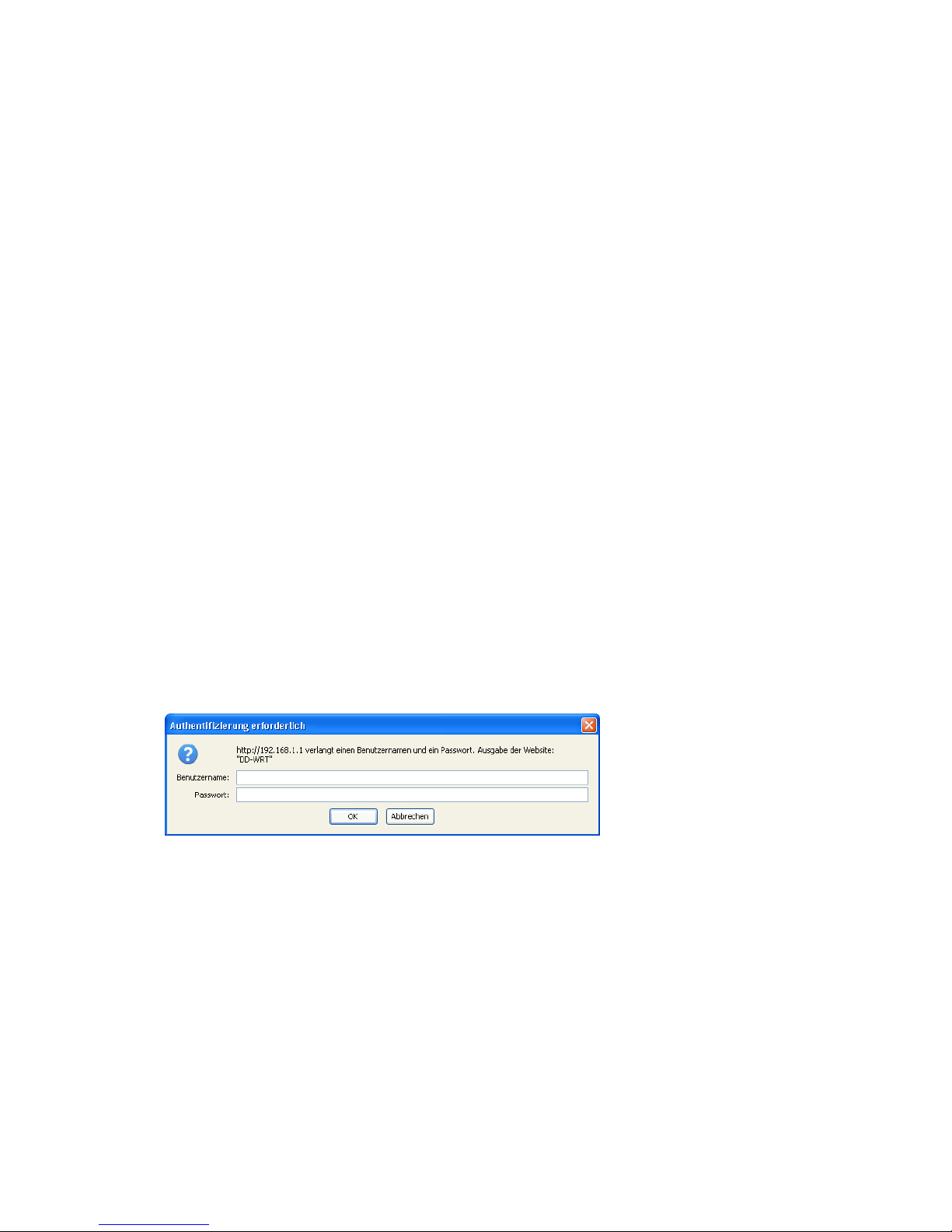
When you click on a tab, the login window will pop up. Enter the
username and password you previously set.
- 4 -
Page 6
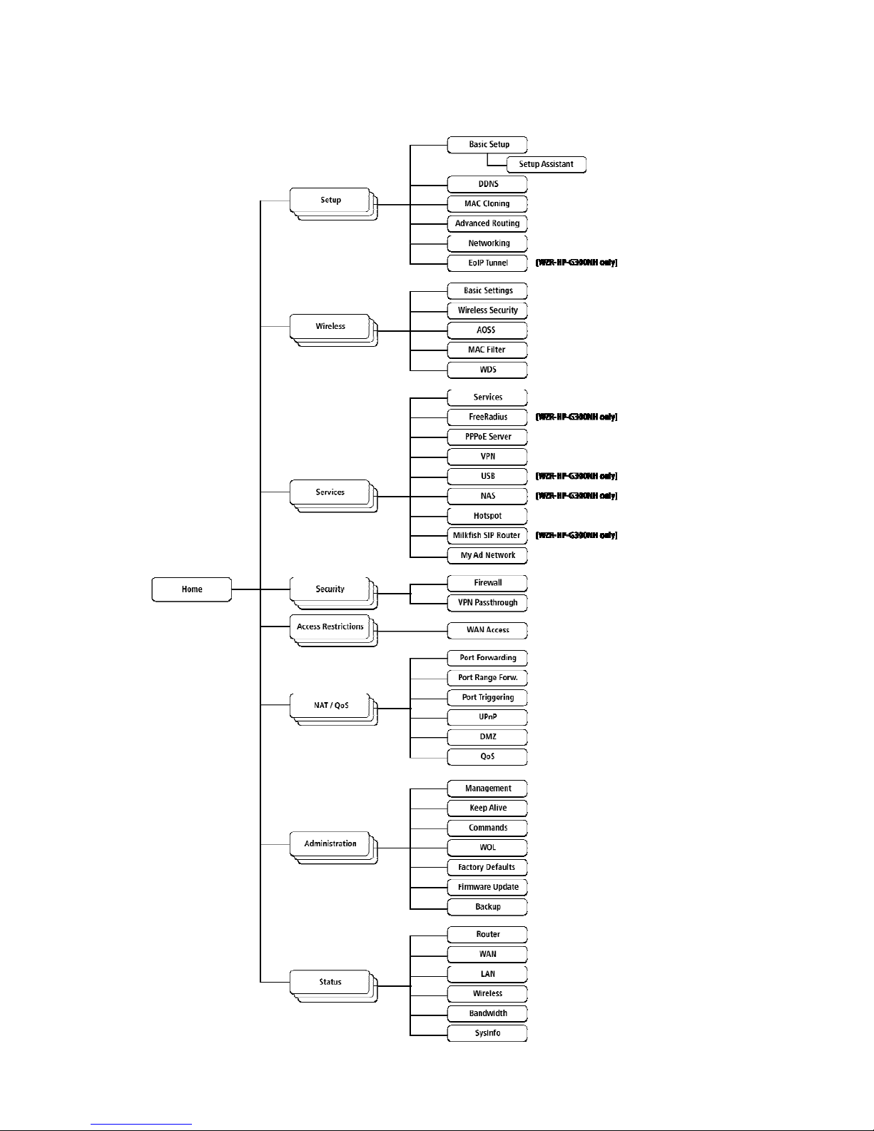
2.3. Web Interface Structure
- 5 -
Page 7

2.3.1. Setup
2.3.1.1. Basic Configuration
Setup Assistant
The setup assistant provides a step-by-step interface for basic router
configuration. This configures most common settings automatically.
WAN Setup
Here you’ll find the most important settings to configure your
internet access and WAN port. DHCP is enabled by default, but you can
also use PPPoE, PPTP, L2TP, static IP, or HeartBeat Signal. If you
don’t use a password to log in to your ISP, you may need to enter
“0000” for the password. Also, for some ISPs you should not enter the
service name, as it will prevent establishing the connection. If you
experience connection problems, then leave the service name empty.
WAN Connection Type Description
Disabled The WAN port is disabled.
Static IP A static IP address will be used – enter the
IP address, subnet mask, gateway, and server
manually.
Automatic
Configuration - DHCP
The router obtains its WAN-side IP address
from a DHCP server.
PPPoE Configure as PPPoE-client. For VDSL, check
the “VDSL-Tagging“ box.
PPTP Establishes connection via PPTP.
L2TP Establishes connection via L2TP.
HeartBeat Signal If you use a HeartBeat connection, consult
your ISP for setup information. HeartBeat
Signal is used only in Australia.
3G/UMTS [WZR-HP-
G300NH only]
Configures Internet Access via 3G/UMTS.
Enable USB in the “Services” section and
attach a 3g/UMTS USB stick to the router.
Network Setup
Network Setup configures the router’s basic settings to match the
local network. By default these settings are valid for all network
ports except the WAN because they are all attached to the default
bridge. If ports are disassociated from the bridge they will have
different settings.
2.3.1.2. Dynamic DNS (DynDNS or DDNS)
Dynamic DNS allows the assignment of a DNS record to a dynamically
assigned WAN-side IP address. A DynDNS client updates DNS records when
your WAN-side IP address changes.
The router’s firmware offers presets for the most common DynDNS
services plus an option to define individual settings.
- 6 -
Page 8

DynDNS Service Description
Disabled Default, no DynDNS
DynDNS.org
freedns.afraid.org
ZoneEdit.com
No-IP.com
3322.org
easyDNS.com
TZO.com
DynSIP.org
Custom Individual DynDNS service configuration
2.3.1.3. MAC Address Cloning
MAC address cloning lets you assign a different MAC address to the
router than the one encoded in the hardware.
2.3.1.4. Advanced Routing
Operating Mode
The default operating mode of the router is Gateway. Other routing
protocols are available.
Modus Description
Gateway Gateway (default)
BGP BGP Routing
Rip2 Router Rip2 Routing
Router Router
Static Routing
The Static Routing section lets you add static routes. The input
parameters are equivalent to the parameters of the Linux command
“route”.
2.3.1.5. Networking
The Networking section allows detailed network configuration.
VLAN Tagging
Use this option to configure VLAN tagging.
Bridging
By default, one bridge (br0) is defined and active. In this section
you can define additional bridges and change the interface assignment
according to your requirements.
Bonding
- 7 -
Page 9

Bonding offers the ability to “bond” interfaces together. Bonding can
be used to enhance throughput or provide failover capabilities.
Port Setup
The port setup section allows further configuration of the routers
network interfaces. Network interfaces can be separated from the
bridge and it is possible to assign separate network settings for each
interface. If an interface is separated from the bridge, add routing
rules to allow communication between the interface and the bridge or
other unbridged interfaces.
DHCPD
Besides the default DHCP server, you can define additional DHCP
servers.
2.3.1.6. EoIP Tunnel [WZR-HP-G300-NH only]
EoIP (Ethernet over IP) tunnels can transport Ethernet data packages
via a tunnel over existing IP connections. You can define up to 10
tunnels that can also be bonded.
2.3.2. Wireless
2.3.2.1. Basic Settings
Each Wireless LAN interface has its own section in the wireless basic
settings screen. The wireless interfaces are labelled ath0 and ath0.1
– ath0.4 depending on the number of radios installed. To correctly
identify the antenna connectors, please compare the MAC addresses
printed on the enclosure with the addresses displayed in the web
interface.
Wireless Mode
This parameter is used to define the operating mode of the Wireless
LAN interface. You can select among the following modes:
Modus Description
AP WLAN Access Point mode (default)
Client WLAN Client mode
Client-Bridge Client-Bridge mode allows connecting to
another Wireless LAN access point and
establishing a network bridge with that
access point
AdHoc AdHoc operating mode, required for building
mesh networks
WDS Station WDS Station is the client in a WDS-AP <-> WDS
station bridge. This is a special wireless
networking mode that offers better
flexibility and security than the classical
MAC address based WDS.
WDS AP WDS AP is the AP side for WDS AP <-> WDS
Station. A WDS AP allows connections from WDS
Stations and Wireless Clients.
- 8 -
Page 10

Wireless Network Mode
Defines the IEEE802.11 networking mode.
Mode Description
Disabled Interface is disabled
Mixed 2.4 GHz 802.11b / 802.11g / 802.11n mixed
mode
B-Only 2.4 GHz 802.11b mode (802.11g and 802.11n
devices cannot connect)
G-Only 2.4 GHz 802.11g mode (802.11b, and 802.11n
devices cannot connect)
BG-Mixed 2.4 GHz 802.11b & 802.11g mixed mode (802.11n
devices cannot connect)
NG-Mixed 2.4 GHz 802.11n & 802.11g mixed mode (802.11b
devices cannot connect)
N-Only (2.4 GHz) 2.4 GHZ 802.11n mode (802.11a, 802.11b, and
802.11g devices cannot connect)
Channel Width
Some wireless network modes support wireless channel widths besides
the standard 20 MHz. 802.11g & 802.11n offer the option to use 40 MHz
channels for enhanced throughput. Both the AP and the client must
support 40 MHz channels to use them.
Wireless Channel (AP only)
Set the desired wireless channel, or let the router choose a free
channel automatically. If the router is in classic WDS (MAC address
based) mode, then the wireless channel must be selected manually.
Wireless Network Name (SSID)
The name of the wireless network the radio transmits or connects to
(depending on the wireless mode)
Wireless SSID Broadcast (AP only)
The name of the wireless network (SSID) may be broadcasted or not.
This does not prevent the network from being detected by a wireless
network sniffer; it just hides the name.
Advanced Settings
Check this box to get access to advanced wireless settings. These
advanced parameters should be only modified by experienced users.
2.3.2.2. Wireless Security
Because wireless data packets can easily be sniffed, wireless
connections require a greater level of security to ensure that data
cannot be read by unauthorized users.
Security Mode
Mode Description
Disabled No encryption set (not recommended!)
- 9 -
Page 11

WPA Personal
WPA encryption with a passphrase (text
password)
WPA Enterprise (AP
only)
WPA encryption with Radius Client
authentication according to 802.1x
WPA2 Personal WPA2 encryption with a passphrase (text
password)
WPA2 Enterprise (AP
only)
WPA2 encryption with Radius Client
authentication according to 802.1x
WPA2 Personal Mixed WPA & WPA2 encryption in WPA/WPA2 mixed mode
with a passphrase (text password)
WPA2 Enterprise Mixed
(AP only)
WPA & WPA2 encryption in WPA/WPA2 mixed with
Radius Client authentication according to
802.1x
RADIUS
WEP WEP 64 Bit / 128 Bit encryption (insecure;
not recommended!)
802.1x (Client only) Client side mode to connect to AP’s working
with WPA Enterprise Modes via RADIUS
authentication
When using WEP encryption (not recommended), the user can choose
between 64 bit and 128 bit keys. Keys can be entered as passphrases
that are used to generate the Hex keys. Theoretically 128 bit keys
offer a higher level of security but because of design flaws, that’s
not the case in actual use.
Key length Description
64 Bit (10
Hexadecimal
characters)
Standard
128 Bit (26
Hexadecimal
characters)
With WPA or WPA2 encryption, there are several encryption algorithms
to choose from. AES is more secure but TKIP is more widely supported.
There is also a TKIP + AES setting, but that does not offer more
security than TKIP.
Algorithm Description
TKIP TKIP encryption, supported by most clients
devices
AES AES encryption offers a better level of
security but might not be supported by a
number of client devices and requires less
cpu processing power.
TKIP + AES Mixed mode – offers best compatibility but
doesn’t work in all environments
If RADIUS security is used, the MAC address format has to be set
accordingly.
- 10 -
Page 12

RADIUS MAC format
options
Description
aabbcc-ddeeff Standard
aabbccddeeff
aa:bb:cc:dd:ee:ff
aa-bb-cc-dd-ee-ff
2.3.2.3. AOSS
AOSS (AirStation Onetouch Secure Setup) is Buffalo Technology’s system
to automatically connect wireless clients to an access point. AOSS can
only be used in AP mode.
Enable AOSS
Enables the AOSS Service. When disabled AOSS cannot be used.
Start AOSS Negotiation
To initiate the AOSS process you can either click the AOSS button in
the GUI or hold down the AOSS button on the front of the router for 3
seconds.
Security Modes
You may choose which security modes are offered in the AOSS
negotiation process. The use of WEP in general is not recommended due
to security concerns.
2.3.2.4. MAC Filter
The MAC Filter defines a list of client MAC addresses that are allowed
to connect wirelessly. MAC addresses that aren’t on the list aren’t
allowed to connect.
2.3.2.5. WDS
Wireless Distribution System (WDS) is a special access point mode that
allows the connection of several access points to form a combined
network. Such a network can be used to extend wireless network
coverage.
The MAC addresses of the access points nearest to the current access
point are entered as WDS nodes. Avoid creating “double” connections,
i.e. A <-> B + A <-> B <-> C. These modes are available to connect WDS
nodes:
WDS Client Mode Description
disabled Standard
Point-to-Point Commonly used mode
LAN
If WDS is enabled, then WDS NAT modes are also available.
- 11 -
Page 13

WDS NAT Mode Description
WLAN -> WDS Standard
WDS -> WLAN
2.3.3. Services
2.3.3.1. Services
The services section allows the configuration of basic service
settings. Telnet and SSH can be configured this way. Remote access
options are configured in the Administration section.
Available DHCP Server
Domains
Description
WAN Standard
LAN / WLAN
Rflow / MACupd
Interface Options
Description
LAN & WLAN Standard
LAN
WLAN
2.3.3.2. FreeRadius [WZR-HP-G300NH only]
Certain applications (for example, Chillispot hotspot software)
benefit from a RADIUS server for management of user credentials and
settings.
Server Certificate
This section contains the parameters to generate the RADIUS server
certificate. The certificate needs to be generated before clients can
be configured to connect to the RADIUS server.
Certificate Status
Displays the server certificate creation status.
Settings
Choose the port that the RADIUS server uses for client communication.
The default port is 1812.
Clients
This section is used to define RADIUS clients (required for HotSpot
usage).
Users
Lists the users defined in the RADIUS servers. Allows creation and
modification of accounts.
- 12 -
Page 14

2.3.3.3. PPPoE Server
Some applications require a PPPoE server on the router, which can be
configured here. The PPPoE server is disabled by default.
2.3.3.4. VPN
The router can also be configured as VPN server or VPN client.
PPTP
When defining the PPTP server’s IP range, avoid overlap with the range
of IP addresses handed out by DHCP if DHCP is enabled. The IP range is
defined using the following syntax:
xxx.xxx.xxx.<start-ip>-<end-ip>
for example
192.168.1.20-30
Enter client login data follows:
<username> * <password> *
for example
testuser * test *
The encryption options can be set as follows
PPTP server type Settings
DD-WRT Router mppe required (Standard)
Windows PPTP Server mppe required,no40,no56,stateless or
mppe required,no40,no56,stateful
OpenVPN [WZR-HP-G300NH only]
OpenVPN is a powerful and flexible VPN solution. OpenVPN security is
based on certificates that cannot created on the router itself. Please
refer to OpenVPN’s online documentation for instructions on creating
certificates and configuring OpenVPN.
2.3.3.5. USB [WZR-HP-G300NH only]
The router’s USB port can be used for several purposes. Here the basic
and advanced USB parameters are defined. Besides enabling USB and
defining the USB hardware standard to use you can also define if
printer and storage support for USB shall be enabled.
2.3.3.6. NAS [WZR-HP-G300NH only]
If USB hard drive support is enabled, you can start the integrated
ProFTPd server to share data on an attached hard disk via FTP.
- 13 -
Page 15

The User/Password data are entered as follows:
<username> * <password> *
for example
testuser * test *
Be careful enabling anonymous login. If anonymous login is enabled,
everybody accessing your network has permission to read and write data.
2.3.3.7. Hotspot
Most hotspot software requires a server to store user settings and
login information. Please note that Sputnik is a commercial hotspot
service that requires an agreement with Sputnik for usage.
2.3.3.8. Milkfish SIP Router [WZR-HP-G300NH only]
This package is an implementation of the Milkfish SIP router.
2.3.3.9. My Ad Network
Allows the creation of an AnchorFree Hotspot that can be used to
create revenue via AnchorFree.
2.3.4. Security
2.3.4.1. Firewall
Aside from enabling and disabling the firewall, you can also set
additional filters, block certain network requests for the WAN
interface, and manage logs.
2.3.4.2. VPN Pass-through
VPN settings effect how the firewall handles IPSec, PPTP, and L2TP
connections. By default, pass-through is enabled. Please note that
disabling pass-through will usually prevent you from establishing VPN
connections from computers located in your local network to VPN
servers on the internet.
2.3.5. Access Restrictions
2.3.5.1. WAN Access
The WAN access settings allow the definition of time and service
related access rules.
2.3.6. NAT / QoS
2.3.6.1. Port Forwarding
Port forwarding allows the assigning of WAN ports to specific internal
IP addresses and matching ports. Bidirectional external traffic can be
- 14 -
Page 16

forwarded to specific internal devices and computers. Each port
forwarding entry defines a source port and a target IP address.
Before adding or removing a port forwarding entry, save all changed
settings. Any changes not saved will be lost when a port forwarding
entry is added or deleted.
2.3.6.2. Port Range Forwarding
Port range forwarding works similarly to port forwarding. Unlike port
forwarding, instead of a single port, a range of ports is forwarded to
the same range of ports at the internal target IP address.
2.3.6.3. Port Triggering
Port triggering is a kind of port range forwarding where outgoing
traffic on specific ports enables previously defined port forwards for
the activating device. This temporarily opens required ports when
specific applications are opened on computers on the LAN. This offers
a greater level of security than port forwarding or port range
forwarding because the ports are only opened when needed.
2.3.6.4. UPnP
UPnP allows UPnP capable applications and devices to open and close
required ports automatically as needed. This is simple to use and does
not require further configuration steps.
2.3.6.5. DMZ
A DMZ computer is a special computer in the internal network that gets
all incoming traffic forwarded. The task of that computer is managing
this traffic. When the DMZ feature is activated the internal firewall
is activated. This can pose a security issue if not handled with care.
Furthermore, several services of the router, that have to be
accessible from the WAN side, will not work because the associated
traffic is forwarded to the DMZ computer.
2.3.6.6. QoS
QoS (Quality of Service) is a procedure to prioritise network traffic
by application. Specific services can be assigned specific bandwidth.
Aside from upstream and downstream bandwidth, you can define settings
for specific services and IP and MAC address ranges.
2.3.7. Administration
2.3.7.1. Management
The Management section contains settings for remotely accessing the
router and other basic settings that are usually not changed. The
settings for the language used in the Web GUI are also located here.
You may choose between Chinese (simplified & traditional), Dutch,
French, German, Hungarian, Italian, Japanese, Polish, Portuguese,
Slovenian, Spanish, and Swedish. The default setting is English.
- 15 -
Page 17

Before using Telnet or SSH, activate the associated service(s) in this
section.
2.3.7.2. Keep Alive
Keep-Alive lets you configure monitoring options that automatically
reboot the router if a service malfunction causes it to fail to
respond.
2.3.7.3. Commands
Entering Linux commands is one of the most powerful ways to access the
router’s functionality. This enables you to access services and
configure options that are not accessible via the Web GUI. Using shell
commands can lead to unexpected results. Use them with utmost care.
Aside from executing the shell commands directly you can also save
custom start up and firewall scripts.
2.3.7.4. WOL
With Wake-on-LAN, you can send special data packets to compatable
devices on your LAN, causing them to exit sleep mode.
WOL data packets can be triggered manually or scheduled automatically.
2.3.7.5. Factory Defaults
With this feature you can reset the router’s settings to factory
defaults. After a reset, the router will restart.
2.3.7.6. Firmware Upgrade
The firmware upgrade option can be used to install a different
firmware version. When doing this you can choose if the router’s
settings will be restored to factory defaults or kept.
2.3.7.7. Backup
You can use this feature to store your current configuration into a
backup file, or to restore from a previously stored configuration.
This also makes it simple to set up a number of routers with the exact
same configuration.
2.3.8. Status
2.3.8.1. Router
The status screen displays information about the router, such as cpu
load, memory consumption, and currently active IP connections. Status
is updated automatically.
- 16 -
Page 18

2.3.8.2. WAN
If the WAN interface is enabled, this screen displays WAN settings and
throughput statistics.
2.3.8.3. LAN
Here you can find LAN-related information like active clients and DHCP
clients.
2.3.8.4. Wireless
The wireless LAN status screen displays the current wireless LAN
interface configuration, wireless LAN clients (in AP modes), and
access points (in client modes). If there’s more than one wireless LAN
interface, you can switch between them via the interface pull down
menu.
2.3.8.5. Bandwidth
Bandwidth monitoring displays real time diagrams for incoming and
outgoing traffic for each network interface.
2.3.8.6. SysInfo
The SysInfo screen combines the most important information of the
other status pages. By default, the SysInfo page can be accessed from
LAN devices without authentication. That can be changed in the
Management section of the Administration area.
- 17 -
Page 19
3. Use Cases
The following use cases relate to the most commonly used router
configurations. The related router configuration is explained step by
step.
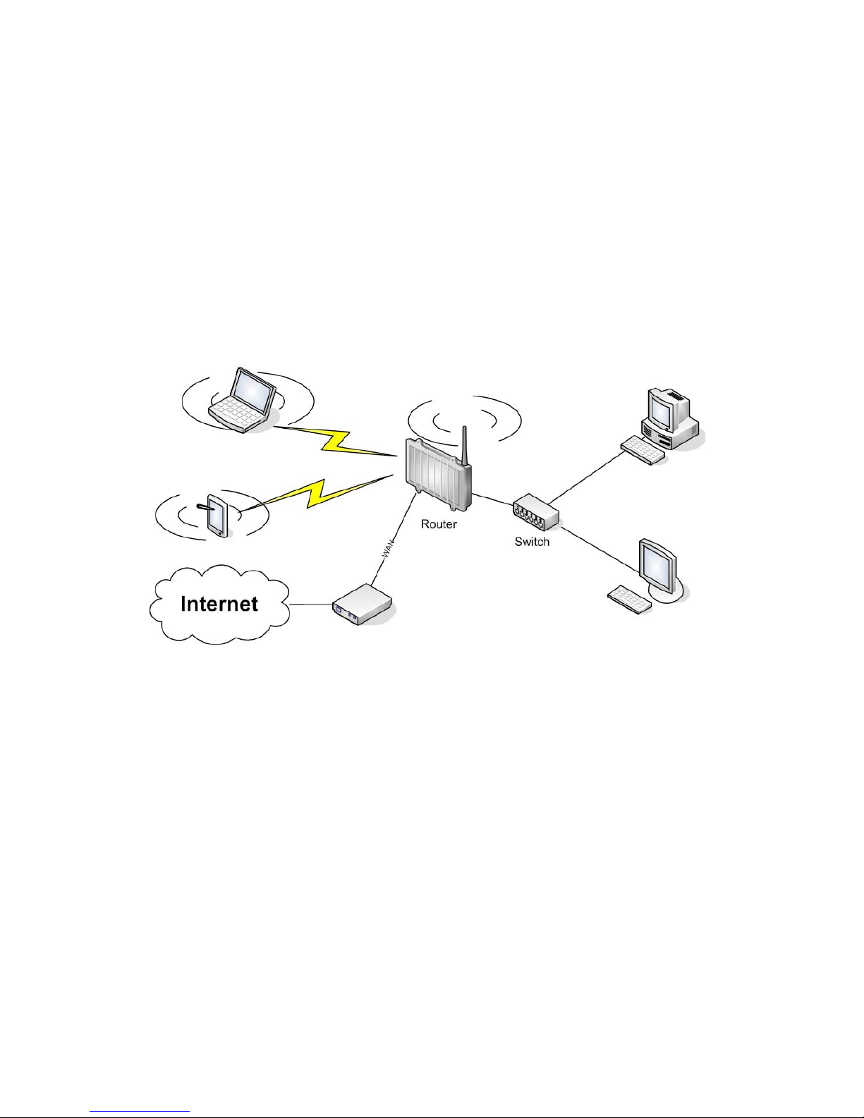
3.1. Access Point
Access Point (AP, sometimes also called “Infrastructure Mode”) is the
mode where the router is also the central wireless hub that connects
to the LAN and provides access to wireless devices. These wireless
clients of the AP can communicate with each other and with wired
devices on the network such as the Internet.
Connect your computer to the router as described in 2.1. and access
the web interface according to 2.2.
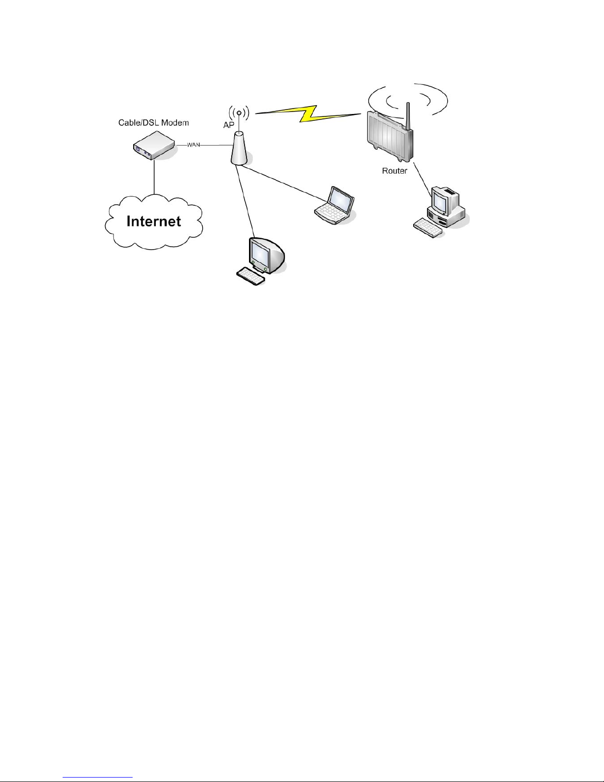
3.1.1. Access Point with NAT / DHCP
Setup -> Basic Setup
WAN Setup
o In ”Connection Type”, choose the type of WAN connection you want
to use and complete the related settings.
Network Setup
o Enter the desired LAN IP address for the router into “Router IP“.
o Set “DHCP Type“ to “DHCP Server“ (this is the default).
o “Enable“ DHCP Server (this is the default).
o Adjust the DHCP address range to match your requirements.
Time Settings
o Choose your time zone.
Click “Save“.
Wireless -> Basic Settings
- 18 -
Page 20

Enter your country in “Regulatory Domain”
In the “Antenna Gain“ field, please enter the gain of the antenna on
your router. The firmware will adjust the transmit power accordingly
to meet regulatory requirements. Please keep in mind that very long
cables can dampen the HF signal thus reducing the usable antenna
gain.
Configure “Wireless Mode“ to “AP“
Set your desired wireless mode in “Wireless Network Mode“. Please
note that mixed modes will lead to reduced performance because of
maintaining compatibility.
Enter a name for your wireless network into “Wireless Network Name
(SSID)”
Click “Save“
Wireless -> Wireless Security
Choose and configure a security mode. Please note that WEP is
insecure and should only be used if no other option is available.
Click “Apply Settings“
You can now connect the router to the Internet and your local network.
After you successfully connect wireless devices, they will then be
displayed on the “SysInfo” and “WLAN Status” pages.
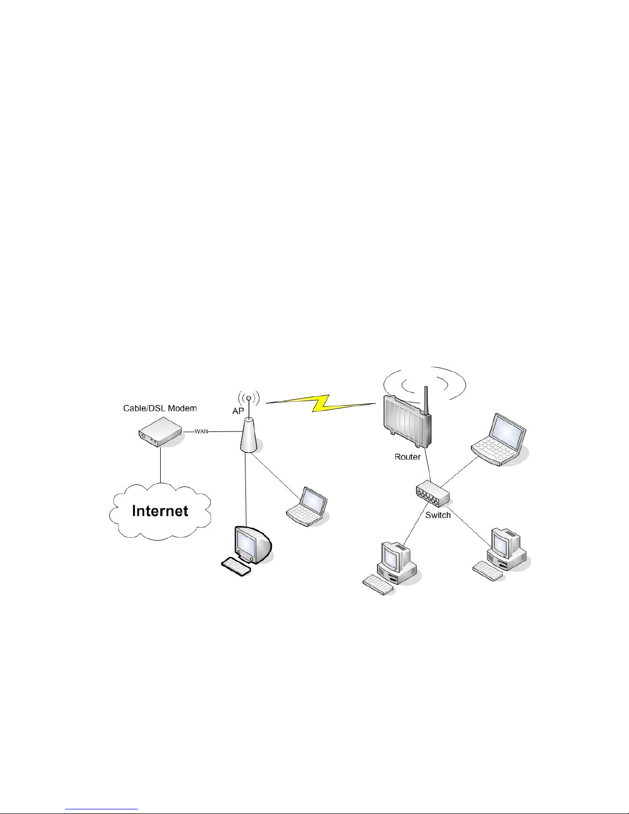
3.1.1. Access Point attached to a network / Internet gateway
Setup -> Basic Setup
WAN Setup
o For “Connection Type“, choose “Disabled”.
Network Setup
o Enter the desired LAN-side IP address for the router into “Router
IP“.
o Set the “DHCP Type“ to “DHCP Server“ (this is the default).
o “Disable” “DHCP Server“.
Time Settings
o Choose your time zone.
Click “Save“.
Wireless -> Basic Settings
Enter your country in “Regulatory Domain”
In the “Antenna Gain“ field, please enter the gain of the antenna on
your router. The firmware will adjust the transmit power accordingly
to meet regulatory requirements. Please keep in mind that very long
cables can dampen the HF signal thus reducing the usable antenna
gain.
Configure “Wireless Mode“ to “AP“
Choose a wireless mode in “Wireless Network Mode“. Please note that
mixed modes will lead to reduced performance because of maintaining
compatibility.
- 19 -
Page 21
Enter a name for your wireless network into “Wireless Network Name
(SSID)”.
Click “Save“.
Wireless -> Wireless Security
Choose and configure your desired security mode. Please note that
WEP is insecure and should only be used if no other option is
available.
Click “Apply Settings“
You can now connect the router to the Internet and your local network.
If you’re running a DHCP server in your LAN, connected wireless
devices will get their IP addresses from the server.
3.2. Wireless Client
The router can be also used as a wireless LAN client. This can be
useful if you want to connect devices to your wireless LAN that do not
have a wireless LAN interface. In this configuration, the wireless LAN
interface acts as a wireless client. Attached wired Ethernet devices
can also access the WAN through the wireless connection.
Setup -> Basic Setup
WAN Setup
o Set “Connection Type“ to “DHCP” to have the AirStation get its IP
address from a DHCP server, or to a “Static IP“ if no DHCP server
is available.
Network Setup
o Enter the desired LAN-side IP address for the router in “Router
IP“.
o Set the “DHCP Type“ to “DHCP Server“ (this is the default setting).
o “Enable” “DHCP Server“ (this is the default setting).
o Adjust the DHCP address range to match your requirements.
- 20 -
Page 22

Time Settings
o Choose your time zone.
Click “Save“.
Wireless -> Basic Settings
Enter your country in “Regulatory Domain”
In the “Antenna Gain“ field, please enter the gain of your
AirStation’s antenna. The firmware will adjust the transmit power
automatically to meet regulatory requirements. Please note that the
use of a long extension cable for your antenna will reduce the
usable antenna gain.
Configure “Wireless Mode“ to “Client“.
Configure “Wireless Network Mode” to match the capabilities of the
access point you want to connect to.
Enter the network name (SSID) of the AP you want to connect to into
“Wireless Network Name (SSID)”.
Click “Save“.
Wireless -> Wireless Security
Configure the security mode to match the security settings of the
access point you want to connect to.
Click “Apply Settings“.
After the router reboots, please confirm that it has connected to the
access point. If there is a DHCP server available on the access point
side, and the router is configured to request an IP address, then it
should receive an IP address for its WAN-side interface.
You can now either connect wired clients to the access point or
configure another wireless network interface as an access point to
grant access to wireless clients.
3.3. Wireless Client Bridge
A wireless client bridge offers the ability to transparently integrate
the router’s LAN into a different LAN that another access point is
connected to. Clients connected to such a router can access devices in
both LANs and vice versa. In that configuration the router’s WAN
interface is disabled.
- 21 -
Page 23
Setup -> Basic Setup
WAN Setup
o Choose “Disabled” for “Connection Type“ (this will be set
automatically).
Network Setup
o Enter the desired LAN-side IP address for the router into “Router
IP“.
o “Disable“ “DHCP Server“.
Time Settings
o Choose your time zone.
Click “Save“.
Wireless -> Basic Settings
Enter your country in “Regulatory Domain”.
In the “Antenna Gain“ field, please enter the gain of your
AirStation’s antenna. The firmware will adjust the transmit power
automatically to meet regulatory requirements. Please note that the
use of a long extension cable for your antenna will reduce the
usable antenna gain.
Configure “Wireless Mode“ to “Client Bridge“.
Set “Wireless Network Mode” to match the access point you want to
connect to.
Enter the network name (SSID) of the AP you want to connect to.
Click “Save“.
Wireless -> Wireless Security
Configure security to match the security settings of the access
point you want to connect to.
Click “Apply Settings“.
After the router reboots, please confirm that it has connected to the
access point. If there is a DHCP server available on the access point
- 22 -
Page 24

side, a pc in the router’s LAN configured to request an address from
DHCP should receive an IP address.
- 23 -
Page 25

4. GPL Statement
The firmware that is used in this product includes software that is
subject to the GNU Public Licence (GPL)/the GNU Lesser Public Licence
(LGPL). To the extent that it is applicable within the context of the
GPL and the LGPL, the conditions of the GPL and the LGPL, as well as
the relevant source codes, are available from the manufacturer. The
code underlying the GPL/LGPL for the software shall be provided,
without any ensuing warranty or liability claims. Please see the
conditions of the GPL/LGPL for further details.
4.1. GNU General Public License
Version 2, June 1991
Copyright (C) 1989, 1991 Free Software Foundation, Inc. 51 Franklin
Street, Fifth Floor, Boston, MA 02110-1301, USA
Everyone is permitted to copy and distribute verbatim copies of this
license document, but changing it is not allowed.
4.1.1. Preamble
The licenses for most software are designed to take away your freedom
to share and change it. By contrast, the GNU General Public License
is intended to guarantee your freedom to share and change free
software--to make sure the software is free for all its users. This
General Public License applies to most of the Free Software
Foundation's software and to any other program whose authors commit to
using it. (Some other Free Software Foundation software is covered by
the GNU Library General Public License instead.) You can apply it to
your programs, too.
When we speak of free software, we are referring to freedom, not price.
Our General Public Licenses are designed to make sure that you have
the freedom to distribute copies of free software (and charge for this
service if you wish), that you receive source code or can get it if
you want it, that you can change the software or use pieces of it in
new free programs; and that you know you can do these things.
To protect your rights, we need to make restrictions that forbid
anyone to deny you these rights or to ask you to surrender the rights.
These restrictions translate to certain responsibilities for you if
you distribute copies of the software, or if you modify it.
For example, if you distribute copies of such a program, whether
gratis or for a fee, you must give the recipients all the rights that
you have. You must make sure that they, too, receive or can get the
source code. And you must show them these terms so they know their
rights.
We protect your rights with two steps: (1) copyright the software, and
(2) offer you this license which gives you legal permission to copy,
distribute and/or modify the software.
Also, for each author's protection and ours, we want to make certain
that everyone understands that there is no warranty for this free
- 24 -
Page 26

software. If the software is modified by someone else and passed on,
we want its recipients to know that what they have is
not the original,
so that any problems introduced by others will not reflect on the
original authors' reputations.
Finally, any free program is threatened constantly by software patents.
We wish to avoid the danger that redistributors of a free program will
individually obtain patent licenses, in effect making the program
proprietary. To prevent this, we have made it clear that any patent
must be licensed for everyone's free use or not licensed at all.
The precise terms and conditions for copying, distribution and
modification follow.
4.1.2. GNU General Public License – Terms and Conditions or Copying,
Distribution and Modification
0. This License applies to any program or other work which contains a
notice placed by the copyright holder saying it may be distributed
under the terms of this General Public License. The "Program", below,
refers to any such program or work, and a "work based on the Program"
means either the Program or any derivative work under copyright law:
that is to say, a work containing the Program or a portion of it,
either verbatim or with modifications and/or translated into another
language. (Hereinafter, translation is included without limitation in
the term "modification".) Each licensee is addressed as "you".
Activities other than copying, distribution and modification are not
covered by this License; they are outside its scope. The act of
running the Program is not restricted, and the output from the Program
is covered only if its contents constitute a work based on the Program
(independent of having been made by running the Program). Whether that
is true depends on what the Program does.
1. You may copy and distribute verbatim copies of the Program's source
code as you receive it, in any medium, provided that you conspicuously
and appropriately publish on each copy an appropriate copyright notice
and disclaimer of warranty; keep intact all the notices that refer to
this License and to the absence of any warranty; and give any other
recipients of the Program a copy of this License along with the
Program.
You may charge a fee for the physical act of transferring a copy, and
you may at your option offer warranty protection in exchange for a fee.
2. You may modify your copy or copies of the Program or any portion of
it, thus forming a work based on the Program, and copy and distribute
such modifications or work under the terms of Section 1 above,
provided that you also meet all of these conditions:
a) You must cause the modified files to carry prominent notices
stating that you changed the files and the date of any change.
b) You must cause any work that you distribute or publish, that in
whole or in part contains or is derived from the Program or any part
- 25 -
Page 27

thereof, to be licensed as a whole at no charge to all third parties
under the terms of this License.
c) If the modified program normally reads commands interactively when
run, you must cause it, when started running for such interactive use
in the most ordinary way, to print or display an announcement
including an appropriate copyright notice and a notice that there is
no warranty (or else, saying that you provide a warranty) and that
users may redistribute the program under these conditions, and telling
the user how to view a copy of this License. (Exception: if the
Program itself is interactive but does not normally print such an
announcement, your work based on the Program is not required to print
an announcement.)
These requirements apply to the modified work as a whole. If
identifiable sections of that work are not derived from the Program,
and can be reasonably considered independent and separate works in
themselves, then this License, and its terms, do not apply to those
sections when you distribute them as separate works. But when you
distribute the same sections as part of a whole which is a work based
on the Program, the distribution of the whole must be on the terms of
this License, whose permissions for other licensees extend to the
entire whole, and thus to each and every part regardless of who wrote
it.
Thus, it is not the intent of this section to claim rights or contest
your rights to work written entirely by you; rather, the intent is to
exercise the right to control the distribution of derivative or
collective works based on the Program.
In addition, mere aggregation of another work not based on the Program
with the Program (or with a work based on the Program) on a volume of
a storage or distribution medium does not bring the other work under
the scope of this License.
3. You may copy and distribute the Program (or a work based on it,
under Section 2) in object code or executable form under the terms of
Sections 1 and 2 above provided that you also do one of the following:
a) Accompany it with the complete corresponding machine-readable
source code, which must be distributed under the terms of Sections 1
and 2 above on a medium customarily used for software interchange; or,
b) Accompany it with a written offer, valid for at least three years,
to give any third party, for a charge no more than your cost of
physically performing source distribution, a complete machine-readable
copy of the corresponding source code, to be distributed under the
terms of Sections 1 and 2 above on a medium customarily used for
software interchange; or,
c) Accompany it with the information you received as to the offer to
distribute corresponding source code. (This alternative is allowed
only for non-commercial distribution and only if you received the
program in object code or executable form with such an offer, in
accord with Subsection b above.)
- 26 -
Page 28

The source code for a work means the preferred form of the work for
making modifications to it. For an executable work, complete source
code means all the source code for all modules it contains, plus any
associated interface definition files, plus the scripts used to
control compilation and installation of the executable. However, as a
special exception, the source code distributed need not include
anything that is normally distributed (in either source or binary
form) with the major components (compiler, kernel, and so on) of the
operating system on which the executable runs, unless that component
itself accompanies the executable.
If distribution of executable or object code is made by offering
access to copy from a designated place, then offering equivalent
access to copy the source code from the same place counts as
distribution of the source code, even though third parties are not
compelled to copy the source along with the object code.
4. You may not copy, modify, sublicense, or distribute the Program
except as expressly provided under this License. Any attempt
otherwise to copy, modify, sublicense or distribute the Program is
void, and will automatically terminate your rights under this License.
However, parties who have received copies, or rights, from you under
this License will not have their licenses terminated so long as such
parties remain in full compliance.
5. You are not required to accept this License, since you have not
signed it. However, nothing else grants you permission to modify or
distribute the Program or its derivative works. These actions are
prohibited by law if you do not accept this License. Therefore, by
modifying or distributing the Program (or any work based on the
Program), you indicate your acceptance of this License to do so, and
all its terms and conditions for copying, distributing or modifying
the Program or works based on it.
6. Each time you redistribute the Program (or any work based on the
Program), the recipient automatically receives a license from the
original licensor to copy, distribute or modify the Program subject to
these terms and conditions. You may not impose any further
restrictions on the recipients' exercise of the rights granted herein.
You are not responsible for enforcing compliance by third parties to
this License.
7. If, as a consequence of a court judgment or allegation of patent
infringement or for any other reason (not limited to patent issues),
conditions are imposed on you (whether by court order, agreement or
otherwise) that contradict the conditions of this License, they do not
excuse you from the conditions of this License. If you cannot
distribute so as to satisfy simultaneously your obligations under this
License and any other pertinent obligations, then as a consequence you
may not distribute the Program at all. For example, if a patent
license would not permit royalty-free redistribution of the Program by
all those who receive copies directly or indirectly through you, then
the only way you could satisfy both it and this License would be to
refrain entirely from distribution of the Program.
If any portion of this section is held invalid or unenforceable under
any particular circumstance, the balance of the section is intended to
- 27 -
Page 29

apply and the section as a whole is intended to apply in other
circumstances.
It is not the purpose of this section to induce you to infringe any
patents or other property right claims or to contest validity of any
such claims; this section has the sole purpose of protecting the
integrity of the free software distribution system, which is
implemented by public license practices. Many people have made
generous contributions to the wide range of software distributed
through that system in reliance on consistent application of that
system; it is up to the author/donor to decide if he or she is willing
to distribute software through any other system and a licensee cannot
impose that choice.
This section is intended to make thoroughly clear what is believed to
be a consequence of the rest of this License.
8. If the distribution and/or use of the Program is restricted in
certain countries either by patents or by copyrighted interfaces, the
original copyright holder who places the Program under this License
may add an explicit geographical distribution limitation excluding
those countries, so that distribution is permitted only in or among
countries not thus excluded. In such case, this License incorporates
the limitation as if written in the body of this License.
9. The Free Software Foundation may publish revised and/or new
versions of the General Public License from time to time. Such new
versions will be similar in spirit to the present version, but may
differ in detail to address new problems or concerns.
Each version is given a distinguishing version number. If the Program
specifies a version number of this License which applies to it and
"any later version", you have the option of following the terms and
conditions either of that version or of any later version published by
the Free Software Foundation. If the Program does not specify a
version number of this License, you may choose any version ever
published by the Free Software Foundation.
10. If you wish to incorporate parts of the Program into other free
programs whose distribution conditions are different, write to the
author to ask for permission. For software which is copyrighted by
the Free Software Foundation, write to the Free Software Foundation;
we sometimes make exceptions for this. Our decision will be guided by
the two goals of preserving the free status of all derivatives of our
free software and of promoting the sharing and reuse of software
generally.
4.1.3. NO WARRANTY
11. BECAUSE THE PROGRAM IS LICENSED FREE OF CHARGE, THERE IS NO
WARRANTY FOR THE PROGRAM, TO THE EXTENT PERMITTED BY APPLICABLE LAW.
EXCEPT WHEN OTHERWISE STATED IN WRITING THE COPYRIGHT HOLDERS AND/OR
OTHER PARTIES PROVIDE THE PROGRAM "AS IS" WITHOUT WARRANTY OF ANY KIND,
EITHER EXPRESSED OR IMPLIED, INCLUDING, BUT NOT LIMITED TO, THE
IMPLIED WARRANTIES OF MERCHANTABILITY AND FITNESS FOR A PARTICULAR
- 28 -
Page 30

PURPOSE. THE ENTIRE RISK AS TO THE QUALITY AND PERFORMANCE OF THE
PROGRAM IS WITH YOU. SHOULD THE PROGRAM PROVE DEFECTIVE, YOU ASSUME
THE COST OF ALL NECESSARY SERVICING, REPAIR OR CORRECTION.
12. IN NO EVENT UNLESS REQUIRED BY APPLICABLE LAW OR AGREED TO IN
WRITING WILL ANY COPYRIGHT HOLDER, OR ANY OTHER PARTY WHO MAY MODIFY
AND/OR REDISTRIBUTE THE PROGRAM AS PERMITTED ABOVE, BE LIABLE TO YOU
FOR DAMAGES, INCLUDING ANY GENERAL, SPECIAL, INCIDENTAL OR
CONSEQUENTIAL DAMAGES ARISING OUT OF THE USE OR INABILITY TO USE THE
PROGRAM (INCLUDING BUT NOT LIMITED TO LOSS OF DATA OR DATA BEING
RENDERED INACCURATE OR LOSSES SUSTAINED BY YOU OR THIRD PARTIES OR A
FAILURE OF THE PROGRAM TO OPERATE WITH ANY OTHER PROGRAMS), EVEN IF
SUCH HOLDER OR OTHER PARTY HAS BEEN ADVISED OF THE POSSIBILITY OF SUCH
DAMAGES.
- 29 -
Page 31

User Manual for User-friendly Firmware
WHR-HP-G300N
AirStation NFINITI HighPower Router and AccessPoint
WHR-HP-GN
AirStation Wireless N Technology HighPower Router and Access point
www.bualotech.com
35011344 ver.03
Page 32

Contents
Chapter 1 - Introduction ...................................................5
Installing Your AirStation ......................................................... 5
Professional or User-friendly? ................................................. 5
Features .................................................................................. 5
Air Navigator CD Requirements .............................................. 6
300/150 Mbps High Speed Mode............................................ 7
Package Contents ................................................................... 7
Hardware Overview ................................................................. 8
Front Panel LED's .......................................................................... 8
Back Panel ..................................................................................... 10
Top ................................................................................................. 11
Bottom ............................................................................................ 11
Right Side ...................................................................................... 12
Chapter 2 - Placing Your AirStation ................................13
Antenna Placement ................................................................. 13
Vertical Placement .................................................................. 13
Horizontal Placement .............................................................. 14
Wall-Mounting ......................................................................... 15
Chapter 3 - Installation ..................................................... 16
Automatic Setup ...................................................................... 16
Windows 7 / Vista / XP ................................................................... 16
Mac OS X ....................................................................................... 16
Other OS ........................................................................................ 16
Manual Setup .......................................................................... 17
Firmware Differences .............................................................. 24
Changing Firmware ................................................................. 24
WHR-HP-GN / WHR-HP-G300N User Manual 1
Page 33

Chapter 4 - Conguration ................................................ 29
Accessing the Web-based Conguration Interface ................. 29
Conguration Menu (Router Mode) ......................................... 31
Conguration Menu (Bridge Mode) ......................................... 33
Setup ....................................................................................... 35
Internet/LAN (LAN Cong) ...................................................... 37
Internet (Router Mode only) ........................................................... 37
PPPoE (Router Mode only) ............................................................ 38
DDNS (Router Mode only) ............................................................. 41
VPN server (Router Mode Only) .................................................... 43
LAN ................................................................................................ 45
DHCP Lease (Router Mode only) .................................................. 47
NAT (Router Mode only) ................................................................ 48
Route ............................................................................................. 49
Wireless Cong ....................................................................... 50
WPS ............................................................................................... 50
AOSS ............................................................................................. 51
Basic .............................................................................................. 53
Advanced ....................................................................................... 56
WMM .............................................................................................. 57
MAC Filter ...................................................................................... 59
Multicast Control ............................................................................ 60
WDS ............................................................................................... 61
Security (Router Mode only) ................................................... 63
Firewall (Router Mode only) ........................................................... 63
IP Filter (Router Mode only) .......................................................... 65
VPN Pass Through (Router Mode only) ........................................ 66
LAN Cong (Router Mode only) .............................................. 67
Port Forwarding (Router Mode only) .............................................. 67
DMZ (Router Mode only) ............................................................... 68
UPnP (Router Mode only) .............................................................. 69
QoS (Router Mode only) ................................................................ 70
WHR-HP-GN / WHR-HP-G300N User Manual 2
Page 34

Admin Cong ........................................................................... 71
Name ............................................................................................. 71
Password ....................................................................................... 72
Time/Date ...................................................................................... 73
NTP ................................................................................................ 74
Access ........................................................................................... 75
Log ................................................................................................. 76
Save/Restore ................................................................................. 77
Initialize/Restart ............................................................................. 78
Update ........................................................................................... 79
Diagnostic ............................................................................... 80
System Info .................................................................................... 80
Logs ............................................................................................... 82
Packet Info ..................................................................................... 83
Client Monitor ................................................................................. 84
Ping ................................................................................................ 85
Chapter 5 - Connect to a Wireless Network ................... 86
Automatic Secure Setup (AOSS/WPS) ................................... 86
Windows 7/Vista (Client Manager V) ............................................. 87
Windows XP (Client Manager 3) .................................................... 88
Mac OS X (AOSS Assistant) .......................................................... 89
Other Devices (e.g. Game Console) .............................................. 90
Manual Setup .......................................................................... 90
Windows 7 (WLAN AutoCong) ..................................................... 90
Windows Vista (WLAN AutoCong) ............................................... 91
Windows XP (Wireless Zero Conguration) ................................... 94
Mac OS X (Wi-Fi) ........................................................................... 95
Chapter 6 - Troubleshooting ............................................ 96
Cannot connect to the Internet over wired connection. ........... 96
Cannot access the web-based conguration utility. ................ 96
WHR-HP-GN / WHR-HP-G300N User Manual 3
Page 35

Cannot connect to the network wirelessly. .............................. 97
You forgot AirStation's SSID, Encryption Key, or Password.
The link speed is slower than 300/150 Mbps
(Maximum link speed is only 130/65Mbps).
Other Tips
................................................................................ 98
........................... 97
... 97
Appendix A - Specications ............................................101
WHR-HP-G300N ..................................................................... 101
WHR-HP-GN
........................................................................... 102
Appendix B - Default Conguration Settings ................103
Appendix C - Checking Wireless Signal Quality
...........108
Appendix D - TCP/IP Settings
..........................................111
Appendix E - Restoring the Default Conguration
Appendix F - Regulatory Compliance
Appendix G - Environmental Information
Appendix H - GPL Information
........................................124
............................. 116
......................123
........115
WHR-HP-GN / WHR-HP-G300N User Manual 4
Page 36

Chapter 1 - Introduction
Installing Your AirStation
To install your AirStation, insert the software CD from your package into your computer and follow
the directions on the screen. For more infomation about installation, turn to chapter 3 of this
manual.
Professional or User-friendly?
This AirStation wireless router comes with two dierent rmware packages. You may use either the
dd-wrt-based Professional rmware or the simple User-friendly rmware. By default, the Professional
rmware is preinstalled for US/EU products, and the User-friendly rmware is preinstalled for AsiaPacic products. Turn to page 24 for instructions on switching between the two rmware packages.
Note : Most of this manual documents the User-friendly firmware. For more information on the
dd-wrt-based Professional firmware, consult the help files in its web-based configuration
interface or go to www.dd-wrt.com/wiki.
Features
Supports IEEE802.11n and IEEE802.11b/g
With support for Wireless-N, Wireless-G, and Wireless-B standards, the AirStations can transfer data
to and from all standard 2.4 GHz wireless clients. The WHR-HP-GN is a single stream, single antenna
version, while the WHR-HP-G300N is a dual stream, dual antenna version, with faster Wireless-N
performance.
Dual speed mode
Dual speed mode makes wireless transmission faster by using 2 channels, allowing 300 Mbps
transmission.
Support for AOSS and WPS
Both AOSS (AirStation One-touch Secure System) and WPS (Wi-Fi Protected Setup) are supported.
These automatic connection standards make connection with compatible wireless devices easier.
WHR-HP-GN / WHR-HP-G300N User Manual 5
Page 37

Chapter 1 Introduction
Security Features
The AirStations are equipped with the following security features:
• AOSS
• WPS
• WPA-PSK (TKIP/AES)
• WPA2-PSK(TKIP/AES)
• WPA/WPA2 mixed PSK
• WEP(128-bit/64-bit)
• Privacy Separator
• MAC ltering
• Stealth SSID
• Firewall with easy rules
Automatic Channel Selection
Monitors wireless interference and automatically assigns the clearest, best channel.
Roaming
You can use multiple AirStations to cover a large area. Wireless clients can automatically switch
AirStations for the best signal.
Initialization
To restore settings back to the factory defaults, hold down the Reset button on the bottom of the
unit.
Browser Based Administration
These units can be easily congured from a password-protected web page though a browser on
your computer.
Auto Mode (Router/Bridge Automatic Recognition)
Auto mode detects whether your network has a router or not and automatically switches to the
appropriate router or bridge mode. You can also manually switch between modes.
Air Navigator CD Requirements
The AirStation wireless router and access point works with most wired and wireless devices. The
automatic installation program on the CD requires Windows 7, Vista, or Windows XP to run. Client
Manager software is included for Windows 7, Vista, and XP. The use of other operating systems may
require that the AirStation be manually congured from a browser window.
WHR-HP-GN / WHR-HP-G300N User Manual 6
Page 38

Chapter 1 Introduction
300/150 Mbps High Speed Mode
With Wireless-N connections, 300 Mbps is the maximum link speed for the WHR-HP-G300N and
150 Mbps is the maximum link speed for the WHR-HP-GN. The speeds are for the total wireless data
transferred including overhead. Because the overhead is not available for transfer of user data, the
wireless throughput usable by the user will be substantially slower.
Package Contents
The following items are included with your AirStation. If any of the items are missing, please contact
your vender.
• Main unit ..............................................................................................1
• Detachable antenna(s) ...................................................................2 for G300N / 1 for GN
• AC adapter ...........................................................................................1
• Stand for vertical/wall-mounting................................................1
• Screws for wall-mounting ..............................................................2
• LAN cable .............................................................................................1
• Air Navigator CD ................................................................................1
• Quick Setup Guide............................................................................1
WHR-HP-GN / WHR-HP-G300N User Manual 7
Page 39

Chapter 1 Introduction
Hardware Overview
Front Panel LED's
1
Hold down this button until the Security LED ashes
1
2
3
4
5
6
2
On: The AC adapter is connected
O: The AC adapter is not connected
3
Indicates security status.
O: Encryption is not set
On: Encryption has been set
Double blink: The unit is waiting for an AOSS or WPS
Blinking: AOSS/WPS error; failed to exchange security keys
AOSS Button
(approximately. 1 second) to initiate AOSS or WPS mode,
allowing the unit to exchange security keys with other AOSS
or WPS compatible devices. Power must be on for this to
work.
Power LED (Green)
Security LED (Amber)
security key
Note: When the Security LED is lit, an encryption key has
been set. Wireless clients will need the same key to
connect.
Wireless LED (Green)
4
Indicates wireless LAN status.
Blinking: Wireless LAN is transmitting
On: Wireless LAN is connected but not active
ROUTER LED (Green) On: Router functionality is enabled
5
Blinking: Router functionality is disabled
DIAG LED (Red) This indicates the status of the unit by the number of blinks per cycle.
6
Note: When the unit is rst turned on or restarted, the Diag LED will
blink for almost a minute during boot. This is normal.
WHR-HP-GN / WHR-HP-G300N User Manual 8
Page 40

Chapter 1 Introduction
Diag LED
Meaning Status
status
2 blinks *
3 blinks *
1
Flash ROM error Cannot read or write to the ash memory.
1
Ethernet (wired) LAN
Ethernet LAN controller is malfunctioning.
error
4 blinks *
1
Wireless LAN error Wireless LAN controller is malfunctioning.
5 blinks IP address setting error Because the network addresses of both the Internet port (WAN
port) and the LAN port are the same, it is not possible to establish
communication. Change the LAN side IP address of this unit.
Continuously
blinking
Updating the rmware
*2
Saving settings
Initializing settings
Updating the rmware.
Saving the settings.
Initializing the settings.
*1 Unplug the AC adapter from the wall socket, wait for a few seconds, and then plug it again. If the
light still ashes, please contact technical support.
*2 Never unplug the AC adapter while the Diag LED is blinking continuously.
WHR-HP-GN / WHR-HP-G300N User Manual 9
Page 41

Chapter 1 Introduction
Back Panel
ТПХФЕТ
ÏÎ
ÏÆÆ
ÁÕÔÏ
ÌÁÎ
ᴮ
ᴯ
8
ᴰ
ᴱ
ЙОФЕТОЕФ
10
РПЧЕТ
7
9
11
12
Router Switch
7
Switches router mode between enabled, disabled, and auto.
On: Router is enabled (router mode).
O: Router is disabled (bridge/AP mode).
Auto: This switches between modes automatically based
on whether or not another router is detected on the
Internet port. The default setting for this switch is
Auto.
LAN LED (Green)
8
On: An Ethernet device is connected.
Flashing: An Ethernet device is communicating.
LAN Port
9
Connect your computer, hub, or other Ethernet devices to
these ports. This switching hub supports 10 Mbps and 100
Mbp
s connections.
Internet LED (Green)
10
On: The Internet (WAN) port is connected.
Flashing: The Internet port is transmitting data.
Internet Port Connect your cable or DSL modem to this port. 10 Mbps and 100 Mbps
11
connections are supported. In bridge/AP mode (router switch o), the
Internet port becomes a regular LAN port, for a total of 5 usable LAN ports.
DC Connector Connect the included AC adapter.
12
WHR-HP-GN / WHR-HP-G300N User Manual 10
Page 42

Chapter 1 Introduction
Top
13
Antenna connector Screw on the antenna(s) here.
13
Bottom
ᵏᵂᵐᵂᵑ
14
Reset Button Hold in this button until the Diag LED comes on to initialize the AirStation’s
14
settings. Power must be on for this to work.
WHR-HP-GN / WHR-HP-G300N User Manual 11
Page 43

Chapter 1 Introduction
Right Side
15
Factory Default Settings
15
This sticker shows the AirStation’s default SSID, encryption
key, and WPS PIN code. By default, encryption is disabled for
AirStations sold in Asia Pacic.
WHR-HP-GN / WHR-HP-G300N User Manual 12
Page 44

Chapter 2 - Placing Your AirStation
Note: Illustrations show the WHR-HP-G300N. The WHR-HP-GN is similar.
Antenna Placement
The antenna(s) are included in the package. The WHR-HP-G300N has two antennas; the WHR-HP-GN
has one. Screw the antenna(s) clockwise to install.
Vertical Placement
To stand the AirStation vertically, attach the base as shown.
1
WHR-HP-GN / WHR-HP-G300N User Manual 13
2
1
Page 45

Chapter 2 Placing Your AirStation
Horizontal Placement
To place the unit horizontally, adjust the antenna(s) as shown.
WHR-HP-GN / WHR-HP-G300N User Manual 14
Page 46

Chapter 2 Placing Your AirStation
Wall-Mounting
1
2
To wall-mount, attach the stand
with screws as shown.
8.5 cm
(~3.3 inches)
Place the center of the AirStation on the
center of the stand and slide downward
to lock in place.
WHR-HP-GN / WHR-HP-G300N User Manual 15
Page 47

Chapter 3 - Installation
Automatic Setup
Windows 7 / Vista / XP
The AirNavigator CD can guide you through installing your AirStation. To launch the setup program
please insert the CD into your Windows 7/Vista/XP PC and follow the instructions on the screen. If
you deactivated auto-run for CD’s please navigate to [CD drive]:\Win\ and launch ASSetWiz.exe.
Note: · To use a wireless client in Windows 7 or Vista, perform setup using the AirNavigator CD to automatically
generate a profile for wirelessly connecting to the AirStation. After setup is complete, once the LAN
cable is removed, you can connect from your wireless client to the AirStation.
· Before performing setup, enable your computer’s wireless client.
Mac OS X
For a Mac, open the Mac folder on the CD and launch the AirStation Conguration tool. Search and
select the Bualo AirStation you want to set up. You can either congure the IP or open the web
interface for all settings. Please refer to “Manual Setup” in the next section.
Note: You can use the easy and simple setup via AOSS to connect the Mac wirelessly. Please press the AOSS but-
ton on the Buffalo router, start the AOSS assistant and follow the steps. The WLAN monitor in the same
folder shows the wireless status regardless which method you use to connect.
Other OS
If your computer uses a dierent operating system, use manual setup instead. Please refer to the
next section “Manual Setup”.
WHR-HP-GN / WHR-HP-G300N User Manual 16
Page 48

ROUTER
LAN
ON
OFF
AUTO
Chapter 3 Installation
Manual Setup
Using AirStation As A Router or An Access Point
To use the AirStation as a router or an access point, congure as below.
1
2
3
4
Turn o your computer and modem.
2) disconnect
2) disconnect
modem
1) turn o the computer
OFF
computer
Unplug the LAN cable that connects
your computer and modem.
Make sure the mode switch on the back of
the AirStation is in the [AUTO] position.
POWER
SECURITY
WEIRELESS
ROUTER
DIAG
Conrm that the
switch is positioned to
AUTO.
Connect one end of the LAN cable to the modem, and connect the other end to the Internet
port of the AirStation. Turn on your modem.
ROUTER
ON
OFF
AUTO
LAN
1
1) connect
2) connect
modem
LAN cable
2
3
4
INTERNET
POWER
INTERNET port
AirStation
WHR-HP-GN / WHR-HP-G300N User Manual 17
Page 49

Chapter 3 Installation
5
6
Connect the AirStation’s LAN port to your computer with another LAN cable.
Turn on the AirStation, wait 60 seconds, and then turn on your computer.
AirStation
ROUTER
ON
OFF
AUTO
1) connect
power outlet
LAN
1
2
3
4
LAN cable
INTERNET
POWER
2) connect the power supply
PC
1) connect
Conrm that the devices are connected correctly as shown below.
computer
ON
7
8
modem
power outlet
After the computer has booted, the LEDs on the AirStation should be in the following condition:
POWER Green light on
WIRELESS Green light on or blinking
ROUTER Green light on or o depending on your network
DIAG O
LAN Green light on or blinking
INTERNET Green light on or blinking
Refer to page 8 and 10 for LED locations and other details.
※
Launch a web browser. If the home page is displayed, setup is complete.
If a user name and password screen is displayed, enter [root] (in lower case) for the user name,
leave the password blank, and click [OK]. Follow the instructions on the screen to complete
setup.
You’ve completed initial setup of your AirStation. Refer to Chapter 4 for advanced settings.
WHR-HP-GN / WHR-HP-G300N User Manual 18
Page 50

ROUTER
LAN
ON
OFF
AUTO
Chapter 3 Installation
Using AirStation As An Ethernet Converter or A Repeater
To use the AirStation as an Ethernet converter or a repeater, follow the directions below.
Using as an Ethernet Converter:
wireless wired
POWER
SECURITY
WEIRELESS
ROUTER
DIAG
router AirStation computer
Using as a repeater:
wireless wireless
POWER
SECURITY
WEIRELESS
ROUTER
DIAG
POWER
SECURITY
WEIRELESS
ROUTER
DIAG
router AirStation computer
In this section, manual conguration is described. However, you can also use AOSS/WPS to congure it.
1
Set your computer’s IP address settings as follows (Appendix D).
IP Address 192.168.11.80
Subnet mask 255.255.255.0
Default gateway 192.168.11.1
Preferred DNS server 192.168.11.1
Alternate DNS server blank
2
Shut down your computer.
3
POWER
SECURITY
WEIRELESS
ROUTER
DIAG
WHR-HP-GN / WHR-HP-G300N User Manual 19
Change the switch position from AUTO to
OFF.
Change the switch
position from AUTO to
OFF.
Page 51

Chapter 3 Installation
4
5
Connect the AirStation’s LAN port to your computer with another LAN cable.
Turn on the AirStation, wait 60 seconds, and then turn on your computer.
AirStation
ROUTER
ON
OFF
AUTO
1) connect
LAN
1
2
3
4
INTERNET
POWER
LAN cable
PC
1) connect
2) connect the power supply
power outlet
Conrm that the devices are connected correctly as shown below.
computer
ON
6
power outlet
After the computer has booted, the LEDs on the AirStation should be in the following condition:
POWER Green light on
WIRELESS Green light on or blinking
ROUTER O
DIAG O
LAN Green light on or blinking
Refer to page 8 and 10 for LED locations and other details.
※
WHR-HP-GN / WHR-HP-G300N User Manual 20
Page 52

Chapter 3 Installation
7
8
9
Launch a web browser.
Enter the LAN IP address of the AirStation in the
address eld, then press the [Enter] key.
Notes: • The default IP address of the AirStation is 192.168.11.100 on access point mode.
• If you have changed the IP address of the AirStation, enter that IP address.
When this screen appears, enter [root] (in lower
case) for the user name and the password that
you set during initial setup. Click [OK].
Notes: • By default, the password is blank (not set).
• If you forget your password, hold down the reset button (page 11) to initialize all settings. The password will then be blank. Note that all other settings will also revert to their default values.
10
WHR-HP-GN / WHR-HP-G300N User Manual 21
Click [Wireless Cong] > [WDS].
Page 53

Chapter 3 Installation
11
If the device you connect supports WDS such as WHR-G300N, WHR-HP-G300N and WZR-HPG300NH, select [Slave] from [Specify Master/Slave] menu and click [Search].
If the device you connect doesn’t support WDS, select [Slave(EC)] from [Specify Master/Slave]
menu and click [Search].
Slave:
Slave(EC):
12
POWER
SECURITY
WEIRELESS
ROUTER
DIAG
POWER
SECURITY
WEIRELESS
ROUTER
DIAG
AirStation
router AirStationBUFFALO Wireless
POWER
SECURITY
WEIRELESS
ROUTER
DIAG
router with WDS
Once the list of the access points is displayed, select the access point you are going to connect to, then click [Select].
If the access point you are going to connect to is not displayed, click [Search again].
WHR-HP-GN / WHR-HP-G300N User Manual 22
Page 54

Chapter 3 Installation
13
14
Enter the encryption settings and password (“key”) for the access point you are connecting
to, then click [Apply].
Change your computer’s IP address settings back to their former values.
ex) IP Address Obtain an IP address automatically
DNS server Obtain DNS server address automatically
15
Note: If using the AirStation as a repeater, unplug the LAN cable from your computer. You’re now con-
nected to the AirStation wirelessly.
Launch a web browser. If your home page is displayed, setup is complete.
WHR-HP-GN / WHR-HP-G300N User Manual 23
Page 55

Chapter 3 Installation
Firmware Differences
You can choose between two dierent rmwares for your AirStation. By default, the Professional
rmware (DD-WRT) is installed. If you prefer, you may install the User-friendly rmware instead. the
two rmwares have slightly dierent features, as shown in the chart below.
Function Professional rmware (DD-WRT) User-friendly rmware
Router switch function
Default administrator name root root (xed)
Default administrator password admin none
AOSS
WPS
WDS
─
a a
─
a a
a
a
Changing Firmware
To change between the professional rmware (dd-wrt) and the user-friendly rmware, follow the
steps below.
Windows
1
Insert the AirNavigator CD into your computer. The setup wizard will automatically launch.
Note: If the Setup Wizard does not launch, open the CD and double-click [ASSetWiz.exe] in the “Win” folder.
2
WHR-HP-GN / WHR-HP-G300N User Manual 24
Click [Change Firmware].
Page 56

Chapter 3 Installation
3
4
The procedure for wiring will be displayed.
Step through the wizard to connect your
AirStation.
When this screen is displayed, click
[Change Firmware].
5
WHR-HP-GN / WHR-HP-G300N User Manual 25
If requested, enter the AirStation’s username
and password.
Note: By default, the Professional rmware doesn’t have
a username and a password congured. Set them
before you go to the next step.
Page 57

Chapter 3 Installation
6
When the following screen is displayed, make sure that the rmware le name is displayed,
click [Upgrade] or [Apply], and follow the instructions on the screen.
Note: If the rmware name is not displayed on the screen, click [Browse...] and select the desired rmware. The
rmware les are contained in the “Firmware” folder of the AirNavigator CD.
Professional rmware (dd-wrt) update screen:
User-friendly rmware update screen:
WHR-HP-GN / WHR-HP-G300N User Manual 26
Page 58

Chapter 3 Installation
Macintosh
1
2
3
Open the conguration Interface of the AirStation.
To replace the professional rmware with the user-friendly rmware, click [Administration] >
[Firmware Upgrade].
To replace the user-friendly rmware with the professional rmware, go to [Easy Setup] and
click [Update AirStation Firmware].
Click [Browse...] to select the rmware le, and click [Upgrade] or [Apply].
Note: The rmware les are contained in the “Firmware” folder of the AirNavigator CD.
Professional rmware (dd-wrt) update screen:
WHR-HP-GN / WHR-HP-G300N User Manual 27
Page 59

Chapter 3 Installation
User-friendly rmware update screen:
WHR-HP-GN / WHR-HP-G300N User Manual 28
Page 60

Chapter 4 - Conguration
The web-based conguration interface lets you change AirStation settings. Don’t change these
settings unless you know what you’re doing.
Accessing the Web-based Conguration Interface
To congure the AirStation’s advanced settings manually, log in to the web-based conguration interface
as shown below.
1
2
3
Launch a web browser.
Enter the AirStation’s LAN-side IP address in the address
eld, and press the enter key.
Note: · The AirStation’s default LAN-side IP address depends on the position of the mode switch.
In router mode: 192.168.11.1
In bridge mode: 192.168.11.100
If the router switch is set to AUTO and the unit is in bridge mode, then the AirStation’s IP address was
assigned by an external DHCP server.
· If you changed the IP address of the AirStation, then use the new IP address.
When this screen appears, enter [root]
(in lower case) for the user name and the
password that you set during initial setup.
Click [OK].
WHR-HP-GN / WHR-HP-G300N User Manual 29
Note: · By default, the password is blank (not set).
· If you forget your password, hold down the
Reset button (page 11) to initialize all
settings. The password will then be blank.
Note that all other settings will also revert to
their default values.
Page 61

Chapter 4 Conguration
4
The conguration interface is
displayed.
Help is always displayed on the
right side of the conguration
utility. Refer to the Help screens for
more information on each page
in the web-based conguration
interface.
WHR-HP-GN / WHR-HP-G300N User Manual 30
Page 62

Chapter 4 Conguration
Conguration Menu (Router Mode)
In router mode, the AirStation’s web-based conguration interface has the following menu screens.
See the pages listed at right for more information about a menu screen.
Main screen Descriptions Page
Internet/LAN
Internet Congure Internet side port and settings Page 37
PPPoE PPPoE settings (DSL login) Page 38
DDNS DNS settings Page 41
VPN Server VPN server settings Page 43
LAN LAN side port and DHCP server conguration Page 45
DHCP Lease DHCP lease settings Page 47
NAT Network address translation settings, used to connect LAN side devices
to the Internet
Route Congure the IP communication route that the AirStation uses Page 49
Wireless Cong
WPS WPS settings and status Page 50
AOSS AOSS (AirStation One-touch Secure System) settings and status Page 51
Basic Congure basic wireless settings Page 53
Advanced Congure advanced wireless settings Page 56
WMM Set priorities for Wireless Multimedia Extensions (Wi-Fi Multimedia) Page 57
MAC Filter Limit access to specic devices Page 59
Multicast Control Congure limits on sending unnecessary multicast packets to the
wireless LAN port
WDS Congure communication among AirStation Page 61
Security
Firewall Protect your computer from outside intruders Page 63
IP Filter Edit IP lters which relates to the packets passing through the LAN side
and the Internet side
Page 48
Page 60
Page 65
VPN
Pass Through
WHR-HP-GN / WHR-HP-G300N User Manual 31
Congure IPv6 passthrough, PPPoE passthrough, and PPTP passthrough Page 66
Page 63

Chapter 4 Conguration
LAN Cong
Port Forwarding Congure port translation and exceptions for games and other programs Page 67
DMZ Congure a destination to transfer communication packets without a
Page 68
LAN side destination.
UPnP Congure UPnP (Universal Plug and Play) Page 69
QoS Congure priority for packets that require a certain data ow Page 70
Admin Cong
Name Congure the AirStation’s name Page 71
Password Congure the AirStation’s login password for access to conguration
Page 72
utilities
Time/Date Congure the AirStation’s internal clock Page 73
NTP Congure the AirStation to synchronize with an NTP server to
Page 74
automatically set the AirStation’s internal clock
Access Congure access restrictions to the AirStation’s conguration utilities Page 75
Log Congure a syslog server to manage the AirStation’s logs Page 76
Save/Restore Save or restore the AirStation’s conguration from a conguration le Page 77
Initialize/Restart Initialize the AirStation or reboot it Page 78
Update Update the AirStation’s rmware Page 79
Diagnostic
System Info View current system information for the AirStation Page 80
Logs Check the AirStation’s logs Page 82
Packet Info View all packets transferred by the AirStation Page 83
Client Monitor View all devices currently connected to the AirStation Page 84
Ping Test the AirStation’s connection to other devices on the network Page 85
Logout
Click this to log out of the AirStation’s web-based conguration interface
WHR-HP-GN / WHR-HP-G300N User Manual 32
Page 64

Chapter 4 Conguration
Conguration Menu (Bridge Mode)
In bridge mode, the AirStation’s web-based conguration interface has the following menu screens.
See the pages listed at right for more information about a menu screen.
Main screen Descriptions Page
LAN Cong
LAN Congure LAN side ports and devices Page 45
Route Congure the IP communication route that the AirStation uses Page 49
Wireless Cong
WPS WPS settings and status Page 50
AOSS AOSS (AirStation One-touch Secure System) settings and status Page 51
Basic Congure basic wireless settings Page 53
Advanced Congure advanced wireless settings Page 56
WMM Set priorities for Wireless Multimedia Extensions (Wi-Fi Multimedia) Page 57
MAC Filter Limit access to specic devices Page 59
Multicast Control Congure limits on sending unnecessary multicast packets to the
wireless LAN port
WDS Congure communication among AirStation Page 61
Admin Cong
Name Congure the AirStation’s name Page 71
Password Congure the AirStation’s login password for access to conguration
utilities
Time/Date Congure the AirStation’s internal clock Page 73
NTP Congure the AirStation to synchronize with an NTP server to
automatically set the AirStation’s internal clock
Access Congure access restrictions to the AirStation’s conguration utilities Page 75
Log Congure a syslog server to manage the AirStation’s logs Page 76
Save/Restore Save or restore the AirStation’s conguration from a conguration le Page 77
Initialize/Restart Initialize the AirStation or reboot it Page 78
Page 60
Page 72
Page 74
Update Update the AirStation’s rmware Page 79
Diagnostic
System Info View current system information for the AirStation Page 80
WHR-HP-GN / WHR-HP-G300N User Manual 33
Page 65

Chapter 4 Conguration
Logs Check the AirStation’s logs Page 82
Packet Info View all packets transferred by the AirStation Page 83
Client Monitor View all devices currently connected to the AirStation Page 84
Ping Test the AirStation’s connection to other devices on the network Page 85
Logout
Click this to log out of the AirStation’s web-based conguration interface.
WHR-HP-GN / WHR-HP-G300N User Manual 34
Page 66

Chapter 4 Conguration
Setup
This is the home page of the conguration interface. You can verify settings and the status of the
AirStation here.
Parameter Meaning
Internet/LAN Congure WAN side network settings.
Wireless Cong Congure wireless settings.
Security Congure security settings.
LAN Cong Open ports for games and applications.
Admin Cong Open the Admin conguration screen.
Diagnostic Gives information and tools for troubleshooting the network.
WHR-HP-GN / WHR-HP-G300N User Manual 35
Page 67

Chapter 4 Conguration
Parameter Meaning
Easy Setup Automatically congures the AirStation’s internet connection.
Internet Information Displays the current internet connection.
Check Connection Checks if the AirStation is connected to the Internet properly.
Refresh Click to refresh the display.
WIRELESS Displays current wireless settings.
AOSS Click to display the AOSS conguration screen.
WPS Click to display the WPS conguration screen.
Network Service List Shows a list of network services.
Language Select the language you use.
Logout Log out of the AirStation’s web-based conguration interface. After
5 minutes of inactivity, the AirStation will log o automatically.
WHR-HP-GN / WHR-HP-G300N User Manual 36
Page 68

Chapter 4 Conguration
Internet/LAN (LAN Cong)
Internet (Router Mode only)
The screen to congure a port of the Internet side.
Parameter Meaning
Method of Acquiring IP Address Species how the current WAN side IP address was obtained.
Default Gateway Specify an IP address for the default gateway.
Address of DNS Name Server Specify an IP address for the DNS server.
Internet MAC Address Congure the Internet side MAC address.
Note: Conguring an improper MAC address may make the AirStation
unusable. Change this setting at your own risk.
MTU size of Internet Port Values between 578 to 1500 bytes may be entered.
WHR-HP-GN / WHR-HP-G300N User Manual 37
Page 69

Chapter 4 Conguration
PPPoE (Router Mode only)
The screen to congure PPPoE settings.
Parameter Meaning
Default PPPoE Connection If you have registered multiple connection destinations in
PPPoE Connection List, connection destinations selected here
have priority. You need to congure the route to which PPPoE is
connected to if you don’t use the default setting.
IP Unnumbered PPPoE Connection Select the destination from the PPPoE Connection List which is
used when specifying [Use IP Unnumbered] in Method of Acquiring
IP Address (page 37).
PPPoE Connection List Edit PPPoE destination. You can register up to 5 sessions.
[Edit Connection List] Click this button to display the screen to edit the settings of
destination.
WHR-HP-GN / WHR-HP-G300N User Manual 38
Page 70

Chapter 4 Conguration
Parameter Meaning
PPPoE Connection No.*-Add Click [Edit Connection List] to display.
Name of Connection
Enter a name to identify the connection. You may enter up to 32
alphanumerical characters and symbols.
User Name
Enter the user name specied by your provider for PPPoE. You
may enter up to 32 alphanumerical characters and symbols.
Password
Enter the password specied by your provider for PPPoE. You may
enter up to 32 alphanumerical characters and symbols.
Service Name
Fill in this eld only when your provider species a Service Name.
Leave blank otherwise. You may enter up to 32 alphanumerical
characters and symbols.
Connection Type
Species the timing for the AirStation to connect to your provider.
Automatic disconnection
Set time to disconnect after communication is stopped when the
connection method is set to [Connect on Demand] or [Manual].
You can enter up to 1440 minutes.
Authorization
Congure an authorization method with a provider.
MTU Size
Congure the MTU value between 578 and 1492 bytes.
MRU Size
Congure the MRU (Maximum Receive Unit) value between 578
and 1492 bytes.
Preferred Connections Displays connections that you’ve added to the preferred connection
list.
[Edit Preferred Connections] Click this button to display the screen to edit the settings of
connection destination route.
WHR-HP-GN / WHR-HP-G300N User Manual 39
Page 71

Chapter 4 Conguration
Parameter Meaning
PPPoE Connection No. *-Add Keep Alive
If Keep Alive is enabled, the AirStation issues LCP echo requests
to maintain the connection with the PPPoE server once a minute.
If the server does not respond after 6 minutes, then the line is
considered disconnected and the AirStation will terminate the
connection. If your PPPoE connection is often disconnected,
disable Keep Alive.
Preferred PPPoE Connection -Add This is displayed when clicking [Edit Preferred Connections].
Name
The name of destination to connect by PPPoE if [Destination
address] and [Source address] of the communication match.
Select the destination registered to PPPoE Connection List.
Destination address
Destination address to communicate. When communicating to
this destination address, the AirStation will communicate with
[Name of Connection].
Source address
Source address to communicate. When communicating from this
source address, the AirStation will communicate with [Name of
Connection].
WHR-HP-GN / WHR-HP-G300N User Manual 40
Page 72

Chapter 4 Conguration
DDNS (Router Mode only)
Congure Dynamic DNS settings.
Parameter Meaning
Dynamic DNS Service Select a provider (DynDNS or TZO) for Dynamic DNS.
User Name
Only when DynDNS is selected
Password
Only when DynDNS is selected
Host Name
Only when DynDNS is selected
Email Address
Only when selecting TZO
TZO Key
Only when selecting TZO
Domain Name
Only when selecting TZO
Enter the user name for the Dynamic DNS service. You may enter up
to 64 alphanumerical characters and symbols.
Enter the password for the Dynamic DNS service. You may enter up
to 64 alphanumerical characters and symbols.
Enter the host name for the Dynamic DNS service. You may enter
up to 255 alphanumerical characters, hyphens, and periods.
Enter the email address which is registered to the Dynamic DNS
service. You may enter up to 64 alphanumerical characters and
symbols.
Enter the TZO Key which is registered to the Dynamic DNS service.
You may enter up to 64 alphanumerical characters and symbols.
Enter the domain name which is registered to the Dynamic DNS
service. You may enter up to 255 alphanumerical characters,
hyphens, and periods.
WHR-HP-GN / WHR-HP-G300N User Manual 41
Page 73

Chapter 4 Conguration
Parameter Meaning
IP Address Update Period Species the period to notify the dynamic DNS service provider of
the current IP address. When DynDNS is selected, set it between 0
and 35 days. When TZO is selected, set it between 0 and 99 days. If
0 (zero) day is set, no periodic update is performed.
Internet Side IP Address The WAN-side IP address of the AirStation’s Internet port. This
address is sent to the dynamic DNS service provider.
Domain Name The domain name assigned by the dynamic DNS Service provider.
The AirStation can be accessed from the Internet using this domain
name.
Status Displays the status of dynamic DNS service.
WHR-HP-GN / WHR-HP-G300N User Manual 42
Page 74

Chapter 4 Conguration
VPN server (Router Mode Only)
Congure a VPN server.
WHR-HP-GN / WHR-HP-G300N User Manual 43
Page 75

Chapter 4 Conguration
Parameter Meaning
Auto Input Click to generate a random IP address.
LAN Side IP Address
DHCP Server
Set a LAN side IP address and subnet mask.
If enabled, the DHCP server will assign LAN-side IP addresses
automatically.
DHCP IP Address Pool
You may choose the range of IP addresses assigned by the DHCP
server and select IP addresses to be excluded from that range.
Values from 0-253 may be entered.
PPTP Server
Authorization Type
Enable to use a PPTP server.
Select the authentication method for PPTP connection.
Server IP Address Select the server IP address.
Client IP Address Select the IP address range.
DNS Server IP Address Set the DNS server IP address for the DHCP server to issue to clients.
WINS Server IP Address Set the WINS server IP address for the DHCP server to issue to cli-
ents.
[Edit User Information] Click to edit user information.
User Name Enter the user name to connect to the PPTP server. You may enter
up to 16 alphanumerical characters and symbols.
Password Enter the password to connect to the PPTP server. You may enter up
to 16 alphanumerical characters and symbols.
Method of Acquiring IP Address Select the method to be used to assign the client’s IP address.
PPTP User List Displays the PPTP connection user information.
WHR-HP-GN / WHR-HP-G300N User Manual 44
Page 76

Chapter 4 Conguration
LAN
Congure LAN-side IP address settings.
Parameter Meaning
LAN Side IP Address Set a LAN side IP address and subnet mask.
DHCP Server Function
Router Mode only
DHCP IP Address Pool
Router Mode only
LAN Side IP Address (IP Unnumbered)
Router Mode only
Advanced Settings
Router Mode only
Lease Period
Router Mode only
Enable or disable the DHCP server, which assigns IP addresses
automatically.
Congure the range of IP addresses to be assigned by the DHCP
server and IP addresses to be excluded from that range. Values from
0-253 may be entered.
Set a LAN side IP address for IP unnumbered.
Note: A PC with a normal LAN side IP address and a PC with an LAN side
IP address for IP Unnumbered cannot communicate each other.
Select Display to display the advanced settings options for the
DHCP server.
Set the eective period of an IP address assigned by the DHCP
server. Up to 999 hours may be entered.
WHR-HP-GN / WHR-HP-G300N User Manual 45
Page 77

Chapter 4 Conguration
Parameter Meaning
Default Gateway
Router Mode only
DNS Servers
Router Mode only
WINS Server
Router Mode only
Domain Name
Router Mode only
Default Gateway
Bridge Mode only
DNS Server Address
Bridge Mode only
Set the default gateway IP address for the DHCP server to issue to
clients.
Set the DNS server IP address for the DHCP server to issue to clients.
Set the WINS server IP address for the DHCP server to issue to
clients.
Set the domain name for the DHCP server to issue to clients. You
may enter up to 127 alphanumerical characters, hyphens, and
periods.
Set the default gateway IP address.
Set the DNS server IP address.
WHR-HP-GN / WHR-HP-G300N User Manual 46
Page 78

Chapter 4 Conguration
DHCP Lease (Router Mode only)
Congure DHCP leases.
Parameter Meaning
IP Address Enter an IP address to lease manually. The IP address should be
from the same subnet as the DHCP scope, but not be within the
range that DHCP is assigning to other devices.
MAC Address Enter the MAC address which identies the client.
Current DHCP Client Information Displays information for current leases. An IP address which is
leased automatically can be changed to be leased manually by
clicking [Manual Assignment].
WHR-HP-GN / WHR-HP-G300N User Manual 47
Page 79

Chapter 4 Conguration
NAT (Router Mode only)
NAT (network address translation) allows your private LAN side network devices to communicate
with the Internet.
Parameter Meaning
Address Translation Enable to use Network Address Translation.
Log Output of Deleted Packets Enable to log deleted packets (such as errors) from address
translation.
WHR-HP-GN / WHR-HP-G300N User Manual 48
Page 80

Chapter 4 Conguration
Route
Congure the AirStation’s IP communication routes.
Parameter Meaning
Destination Address Adds a destination IP address and subnet mask to a routing table.
Gateway Adds a gateway address to a routing table.
Metric The metric is the maximum number of router hops a packet may
take on the way to its destination address. Values between 1 and 15
may be entered. The default value is 15.
Routing Information Manual entries will appear here after being added.
WHR-HP-GN / WHR-HP-G300N User Manual 49
Page 81

Chapter 4 Conguration
Wireless Cong
WPS
Congure WPS settings.
Parameter Meaning
WPS Enable to use WPS automatic conguration.
External Registrar Enable to accept external congure requests from other WPS
devices.
Note: External congure requests will not be accepted if AOSS is in use.
AirStation PIN Displays the PIN code of the AirStation. Clicking [Generate PIN]
will generate a new PIN code. This code can be entered into other
wireless devices that support WPS.
Enrollee PIN Enter the PIN code for the other wireless device and click [OK].
WPS status Displays [congured] if all available wireless bands are
congured. Displays [uncongured] if at least one wireless band is
uncongured.
WHR-HP-GN / WHR-HP-G300N User Manual 50
Page 82

Chapter 4 Conguration
AOSS
Congure and use AirStation One-touch Secure System (AOSS).
WHR-HP-GN / WHR-HP-G300N User Manual 51
Page 83

Chapter 4 Conguration
Parameter Meaning
Initiates AOSS automatic wireless conguration. Click this, then
press or click the AOSS button on your AOSS-compatible wireless
client. Repeat for additional AOSS clients.
Click this button to disconnect all AOSS connections.
Note: If AOSS connections are disconnected, the SSID and encryption keys
will be restored to their most recent settings before using AOSS.
Encryption Type of Exclusive SSID for
WEP
You may allow a separate SSID specically for WEP connections. If
[disabled] is selected, then clients will not be able to connect with
WEP.
Encryption level expansion function Expands security method from TKIP to WPA/WPA2-PSK-mixed
mode.
Dedicated WEP SSID isolation Set a separate SSID and network segment specically for WEP
connections. Devices connected with WEP will not be able
to communicate with devices connected using AES/TKIP. All
connected devices will be able to communicate with the internet.
AOSS Button on the AirStation Unit Normally, pressing the physical AOSS button on the AirStation
initiates AOSS. If this box is unchecked, it will not, and the button
on this page will be the only way to initiate AOSS.
Current Encryption Information
AOSS Connection only
Displays the encryption type, SSID, and encryption key that AOSS
has congured.
[Random] Click to enter random values for SSID, encryption key, and other
settings.
[KEY base] Click to return the SSID, encryption key, and other wireless settings
[Reset] Click to return the SSID, encryption key, and other wireless settings
AOSS Client Information
AOSS Connection only
AOSS Ethernet Converter Information
AOSS Connection only
WHR-HP-GN / WHR-HP-G300N User Manual 52
to the values on the case sticker.
to their previous values.
Displays basic information for AOSS clients connected to the
AirStation.
Displays basic information for Ethernet converters connected to the
AirStation via AOSS.
Page 84

Chapter 4 Conguration
Basic
Congure basic wireless settings.
Parameter Meaning
Wireless Radio Determines whether or not to allow wireless communication. If this
is unchecked, then no wireless connections will be allowed.
Wireless Channel Sets a channel (a range of frequencies) used for wireless
connections. Channels 1-11 are available. If Auto Channel selected,
the AirStation will automatically use the best available channel.
300 Mbps Mode (WHR-HP-G300N)
150 Mbps Mode (WHR-HP-GN)
WHR-HP-GN / WHR-HP-G300N User Manual 53
300/150 Mbps mode uses twice the normal frequency range, 40
MHz instead of 20 MHz. In uncongested areas this can increase
performance. To use 300/150 Mbps mode, set the Bandwidth to 40
MHz and choose an Extension Channel.
Note: If using Auto Channel for the wireless channel, then the Extension
Channel is set automatically.
Page 85

Chapter 4 Conguration
Parameter Meaning
Broadcast SSID If [Allow] is checked, then the AirStation will respond to SSID
searches from wireless devices by broadcasting its SSID. If [Allow] is
unchecked, then the AirStation ignore SSID searches from wireless
devices.
[Use Multi Security function]
[Do not use Multi Security function]
Clicking [Use Multi Security function] will enable Multi Security,
allowing the use of multiple SSIDs, each with dierent wireless
security settings. Clicking [Do not use Multi Security function] will
disable the Multi Security function. The AirStation will then allow
one SSID and one type of wireless security.
Note: When using Multi Security, you need to enable at least one of the
following SSID1, SSID2, or SSID3.
SSID1 Multi Security SSID1 can use WPA-PSK-TKIP or WPA/WPA2-Mixed for
wireless security.
SSID2 Multi Security SSID2 can use WPA-PSK-AES for wireless security.
SSID3 Multi Security SSID3 can use WEP for wireless security.
Separate feature When [Use] is checked, wireless devices connected to the AirStation
can communicate only with the Internet side, not with each other.
SSID SSIDs may contain 1-32 alphanumeric characters.
Wireless authentication Choose an authentication method for wireless connections.
WHR-HP-GN / WHR-HP-G300N User Manual 54
Page 86

Chapter 4 Conguration
Parameter Meaning
Wireless encryption Select a type of data encryption for wireless communication from
the following options:
No encryption
Data is transmitted without encryption. Avoid this option since
any communication may be intercepted.
[No encryption] can be selected only when [No authentication] is
selected for wireless authentication.
WEP
WEP is a common encryption method supported by most devices.
It uses an encryption key. WEP can only be selected when [No
authentication] is selected for wireless authentication.
TKIP
TKIP is an encryption method which is more secure than WEP, but
slower. Use an pre-shared-key to communicate with a wireless
device. TKIP can be selected only when WPA-PSK or WPA2-PSK is
selected for wireless authentication.
AES
AES is more secure than TKIP, and faster. Use a pre-shared-key to
communicate with a wireless device.
AES can be selected only when WPA-PSK or WPA2-PSK is selected
for wireless authentication.
TKIP/AES mixed mode
TKIP/AES mixed mode allows both TKIP and AES authentication.
TKIP/AES mixed mode can be selected only when WPA/WPA2
mixed mode - PSK is selected for wireless authentication.
WPA-PSK (Pre-Shared Key) There are two dierent ways to enter pre-shared keys. Character
keys may contain between 8 and 63 case-sensitive alphanumeric
characters. Hexadecimal keys contain exactly 64 characters. Only 0 9 and a - f (not case-sensitive) should be used in hexadecimal keys.
Rekey interval The rekey interval determines how often an encryption key is
updated. Values from 0 to 1440 minutes may be entered.
Setup WEP encryption key There are two dierent ways to enter WEP encryption keys.
Character keys may contain either 5 or 13 case-sensitive
alphanumeric characters. Hexadecimal keys may contain either 10
or 26 digits. Only 0 - 9 and a - f (not case-sensitive) should be used
in hexadecimal keys.
WHR-HP-GN / WHR-HP-G300N User Manual 55
Page 87

Chapter 4 Conguration
Advanced
Don’t change advanced wireless settings unless you know what you’re doing.
Parameter Meaning
Multicast Rate Set the communication speed of multi-cast packets.
DTIM Period Set the interval (1 -255) for the beacon to respond to a wireless
device. This setting is only eective when power management is
enabled on the wireless device.
Privacy Separator If enabled, the Privacy Separator blocks communication between
wireless devices connected to the AirStation. Wireless devices will
be able to connect to the Internet but not with each other. Devices
that are connected to the AirStation with wired connections will
still be able to connect to wireless devices normally.
WHR-HP-GN / WHR-HP-G300N User Manual 56
Page 88

Chapter 4 Conguration
WMM
Congure QoS priorities here.
WHR-HP-GN / WHR-HP-G300N User Manual 57
Page 89

Chapter 4 Conguration
Parameter Meaning
WMM-EDCA Parameters You don't usually need to change these settings. Using the default
settings is recommended.
Priority
The following priorities may be applied to individual transmission
packets: (Highest) 8, (High) 4, (Normal) 2, and (Low) 1. From the
queue, these packets are processed in order of priority.
CWmin, CWmax
The maximum and minimum value of the contention window.
The contention window is used in the frame collision avoidance
structure performed in IEEE802.11, and generally the smaller the
value in the window, the higher the probability that the queue
obtains the right to send.
AIFSN
The interval to send frames. The unit of the AIFSN is a slot, just as
the window dened by CWmin and CWmax is. The smaller the
interval of sending frames, the faster the algorithm can restart. As
a result, the priority of the queue is higher.
TXOP Limit
The period of time that the queue can use after obtaining the
right to send. The unit is 32 ms. The longer this time, the more
frames can be sent per right to send. However, the que may
interfere with other packet transmissions. If TXOP Limit is set to 0
(zero), only one frame can be sent per right to send.
Admission Control
Restricts new frames from interfering with a previous queue. New
packets are prioritized lower until a queue of them is collected. As
the new queue accumulates more packets, its priority increases.
WHR-HP-GN / WHR-HP-G300N User Manual 58
Page 90

Chapter 4 Conguration
MAC Filter
This screen lets you restrict wireless access to wireless devices with specic MAC addresses.
Parameter Meaning
Enforce MAC Filtering Enable to restrict wireless connections to devices with registered
MAC addresses.
Registration List Displays the MAC addresses of registered devices which are
permitted to connect wirelessly.
[Edit Registration List] Click this button to add a MAC address of a wireless device to the
list of permitted devices.
MAC Addresses to be Registered Enter a MAC address of a wireless device you permit to connect to
the AirStation. Click [Register] to add that MAC address to the list.
List of all clients that are associated
with this AirStation
WHR-HP-GN / WHR-HP-G300N User Manual 59
Display the list of all MAC addresses of wireless devices connected
to the AirStation.
Page 91

Chapter 4 Conguration
Multicast Control
Restrict unnecessary multicast packets from wireless LAN ports.
Parameter Meaning
Snooping If enabled, snooping supervises multicast administrative packets
such as IGMP and restricts unnecessary multicast transfers to wired
or wireless ports.
Multicast Aging Time Set the time to hold the data from multicast snooping in the range
of 1 to 3600 (seconds). Enter a value larger than the interval of a
IGMP/MLD query.
WHR-HP-GN / WHR-HP-G300N User Manual 60
Page 92

Chapter 4 Conguration
WDS
WDS bridging allows communication between AirStations.
Parameter Meaning
WDS Check to use WDS bridging.
Specify Master/Slave Dene this AirStation's role in a WDS bridge.
Master
This AirStation will the master in a WDS bridge. It will have the
Internet connection, and other AirStations in the bridge will be
connected through this AirStation.
Slave
Set AirStation as a slave.
This can be connected with the AirStation which is set as a master
by using WDS feature only if the Master AirStation supports WDS.
Slave (EC)
Set AirStation as a slave.
This uses Ethernet Converter to connect with the AirStation which
is set as a master, so it can be connected even though Master
AirStation does not support WDS.
Auto
Automatically switches between Master and Slave modes
depending on the surrounding network.
If an AirStation works as a router, it will automatically be set as a
master.
If the Airstation works as a bridge and a DHCP server exists
in the network, it will automatically be set as a master . If the
AirStation works as a bridge and no DHCP server is available, it
will automatically be set as a slave.
WHR-HP-GN / WHR-HP-G300N User Manual 61
Page 93

Chapter 4 Conguration
Parameter Meaning
SSID Congure the Master Airstation's SSID.
Search
[
]
Click to search for other AirStations' SSIDs.
Wireless authentication Congure authentication method for the master AirStation
Encryption for wireless Choose encryption type for the master AirStation.
WPA-PSK (Pre Shared Key) Set the master AirStation's Encryption key.
Notes: A master AirStation can communicate with two slaves only.
A slave AirStation cannot communicate with any AirStation other than its master.
Master
Slave1
POWER
SECURITY
WEIRELESS
ROUTER
DIAG
Slave2
POWER
SECURITY
WEIRELESS
ROUTER
DIAG
POWER
SECURITY
WEIRELESS
ROUTER
DIAG
POWER
SECURITY
WEIRELESS
ROUTER
DIAG
POWER
SECURITY
WEIRELESS
ROUTER
DIAG
POWER
SECURITY
WEIRELESS
ROUTER
DIAG
WHR-HP-GN / WHR-HP-G300N User Manual 62
Page 94

Chapter 4 Conguration
Security (Router Mode only)
Firewall (Router Mode only)
Parameter Meaning
Log Output Enable to output a log of rewall activity.
Basic Rules Enable to use any of the quick lters. Precongured quick lters
include:
Prohibit NBT and Microsoft-DS Routing
When enabled, this prevents Microsoft networking from
communicating between the LAN side and the WAN side. You
can congure this with PPPoE if you select [Use PPPoE Client] or
[Use IP Unnumbered] in Method of Acquiring IP address, or if Easy
Setup identied a PPPoE connection during setup.
WHR-HP-GN / WHR-HP-G300N User Manual 63
Page 95

Chapter 4 Conguration
Parameter Meaning
Reject IDENT Requests
Enabling this option will answer IDENT requests from the Internet
side with corresponding rejection packets. Enable this option
if you experience slow transfer speeds for network applications
such as email, ftp, or browsing. If you have congured transfer of
IDENT requests to the LAN side in the address translation settings
(DMZ or TCP port:113), that setting has higher priority, and
overrides this setting.
Block Ping from Internet
If this is enabled, the AirStation will not respond to pings from the
Internet side. You can congure this with PPPoE if you select [Use
PPPoE Client] or [Use IP Unnumbered] in Method of Acquiring IP
address (page 37), or if Easy Setup identied a PPPoE connection
during setup.
WHR-HP-GN / WHR-HP-G300N User Manual 64
Page 96

Chapter 4 Conguration
IP Filter (Router Mode only)
Create and edit IP lters.
Parameter Meaning
Log Output If enabled, IP lter activity is saved to a log.
Operation Specify how to process target packets.
Direction Specify the transmission direction of target packets.
IP Address Specify the sender's IP address and receiver's IP address of the
Protocol Select a protocol for target transmission packet.
IP Filter Information Display the list of IP lters which have been registered.
WHR-HP-GN / WHR-HP-G300N User Manual 65
target packets.
Page 97

Chapter 4 Conguration
VPN Pass Through (Router Mode only)
Congure IPv6 pass through, PPPoE pass through, and PPTP pass through.
Parameter Meaning
IPv6 Pass Through Enable to use IPv6 Pass Through for address translation.
PPPoE Pass Through Enable to use PPPoE bridge. Using PPPoE bridge lets you
automatically obtain an IP address from your provider using the
PPPoE protocol from your computer connected to the LAN side
because all PPPoE packets can pass through between the Internet
and LAN.
PPTP Pass Through Enable to use PPTP Pass Through for address translation.
WHR-HP-GN / WHR-HP-G300N User Manual 66
Page 98

Chapter 4 Conguration
LAN Cong (Router Mode only)
Port Forwarding (Router Mode only)
Congure port translation.
Parameter Meaning
Group Specify a group name for a new rule to belong to. Select [New
Internet Side IP Address Enter the Internet side IP address (before translation) for the port
Protocol Select the Internet side protocol (before translation) for the port
WHR-HP-GN / WHR-HP-G300N User Manual 67
Group] and enter the new group name in the Group Name
eld to create a new group. A group name can include up to 16
alphanumeric letters.
translation table entry.
translation table entry.
Page 99

Chapter 4 Conguration
Parameter Meaning
LAN Side IP Address Enter the LAN side IP address (after translation) for the port
translation table entry.
LAN Side Port Select the LAN side (after translation) port number (1 - 65535) for
the port translation table entry.
Port Forwarding Registration
Information
Shows current entries in the port translation table.
DMZ (Router Mode only)
Congure a destination to transfer communication packets without a LAN side destination.
Parameter Meaning
IP Address of DMZ Enter the IP address of the destination to which packets which are
WHR-HP-GN / WHR-HP-G300N User Manual 68
not routed by a port translation table are forwarded.
Note: RIP protocol packets (UDP port number 520) will not be
forwarded.
Page 100

Chapter 4 Conguration
UPnP (Router Mode only)
Congure Universal Plug and Play.
Parameter Meaning
UPnP Enable or disable Universal Plug and Play (UPnP) functionality.
WHR-HP-GN / WHR-HP-G300N User Manual 69
 Loading...