

Buffalo AirStation WHR-300HP2, AirStation WHR-600D User Manual
AirStation
WHR-300HP2 / WHR-600D
User Manual
www.buffalotech.com
35020160-02
2014-02

Contents
Chapter 1 - Product Overview ..........................................6
Package Contents .................................................................................6
Diagrams and Layout ...........................................................................6
Front Panel ......................................................................................................6
Back Panel .......................................................................................................8
Bottom .............................................................................................................9
Chapter 2 - Installation ....................................................10
Initial Setup ........................................................................................10
Chapter 3 - Configuration ...............................................12
Accessing Settings .............................................................................12
Setup ...................................................................................................14
WAN / LAN ...........................................................................................15
Internet ..........................................................................................................15
PPPoE .............................................................................................................16
DDNS ..............................................................................................................18
PPTP Server ...................................................................................................19
LAN .................................................................................................................20
DHCP ..............................................................................................................21
NAT .................................................................................................................21
Routing ..........................................................................................................22
Wireless ...............................................................................................23
2

WPS ................................................................................................................23
AOSS...............................................................................................................24
Basic ...............................................................................................................25
Advanced .......................................................................................................27
WMM ..............................................................................................................28
MAC Filter ......................................................................................................29
WDS ................................................................................................................30
Multicast Control ..........................................................................................30
Firewall ................................................................................................31
Firewall ..........................................................................................................31
IP Filter ...........................................................................................................32
VPN Passthrough ..........................................................................................33
Games / Apps ......................................................................................34
Port Forwarding ............................................................................................34
DMZ ................................................................................................................35
UPnP ...............................................................................................................35
QoS .................................................................................................................36
Admin ..................................................................................................37
Name ..............................................................................................................37
Password........................................................................................................37
Time and Date ...............................................................................................38
NTP .................................................................................................................38
eco Mode .......................................................................................................39
Access .............................................................................................................40
Syslog Settings ..............................................................................................41
Save/Restore .................................................................................................41
Initialize/Restart ...........................................................................................42
Update ...........................................................................................................42
3

Diagnostic ...........................................................................................43
System Info ....................................................................................................43
Logs ................................................................................................................44
Packet Info .....................................................................................................44
Client Monitor ...............................................................................................45
Ping ................................................................................................................45
Chapter 4 - Connect to a Wireless Network ...................46
Automatic Secure Setup (AOSS / WPS) .............................................46
WIndows 8.1, Windows 8, Windows 7, or Windows Vista (Client Manager V)
Windows XP (Client Manager 3) ...................................................................48
Mac OS (AOSS Assistant) ..............................................................................48
Other Devices (e.g. Game Console) .............................................................49
..47
Manual Setup .....................................................................................50
Windows 8.1/Windows 8 (WLAN AutoConfig) ............................................50
Windows 7 (WLAN AutoConfig) ...................................................................51
Windows Vista (WLAN AutoConfig) .............................................................52
Windows XP (Wireless Zero Configuration) ................................................54
Mac OS (Wi-Fi) ...............................................................................................56
Chapter 5 - Troubleshooting ...........................................57
Cannot Connect to the Internet Over a Wired Connection .............57
Cannot Access Settings ......................................................................57
Cannot Connect to the Network Wirelessly .....................................58
Forgot AirStation’s SSID, Encryption Key, or Password ...................58
How to Configure TCP/IP ...................................................................59
4

Windows 8.1/Windows 8 ..............................................................................59
Windows 7 .....................................................................................................60
Windows Vista ...............................................................................................61
Windows XP ...................................................................................................62
Mac OS ...........................................................................................................62
Other Tips ...........................................................................................63
Chapter 6 - Default Configuration Settings ...................65
WHR-300HP2 ......................................................................................65
WHR-600D ..........................................................................................69
Appendix A - Supplemental Information ......................73
Technical Specifications ....................................................................73
WHR-300HP2 .................................................................................................73
WHR-600D .....................................................................................................74
Environmental Information ..............................................................75
GPL Information .................................................................................75
5
Chapter 1 - Product Overview
Package Contents
The following items are included in your AirStation package. If any of the items are missing, please contact your vender.
AirStation.................................................1
AirStation setup card..........................1
AC adapter...............................................1
Ethernet cable........................................1
Quick setup guide................................1
Warranty statement.............................1
Diagrams and Layout
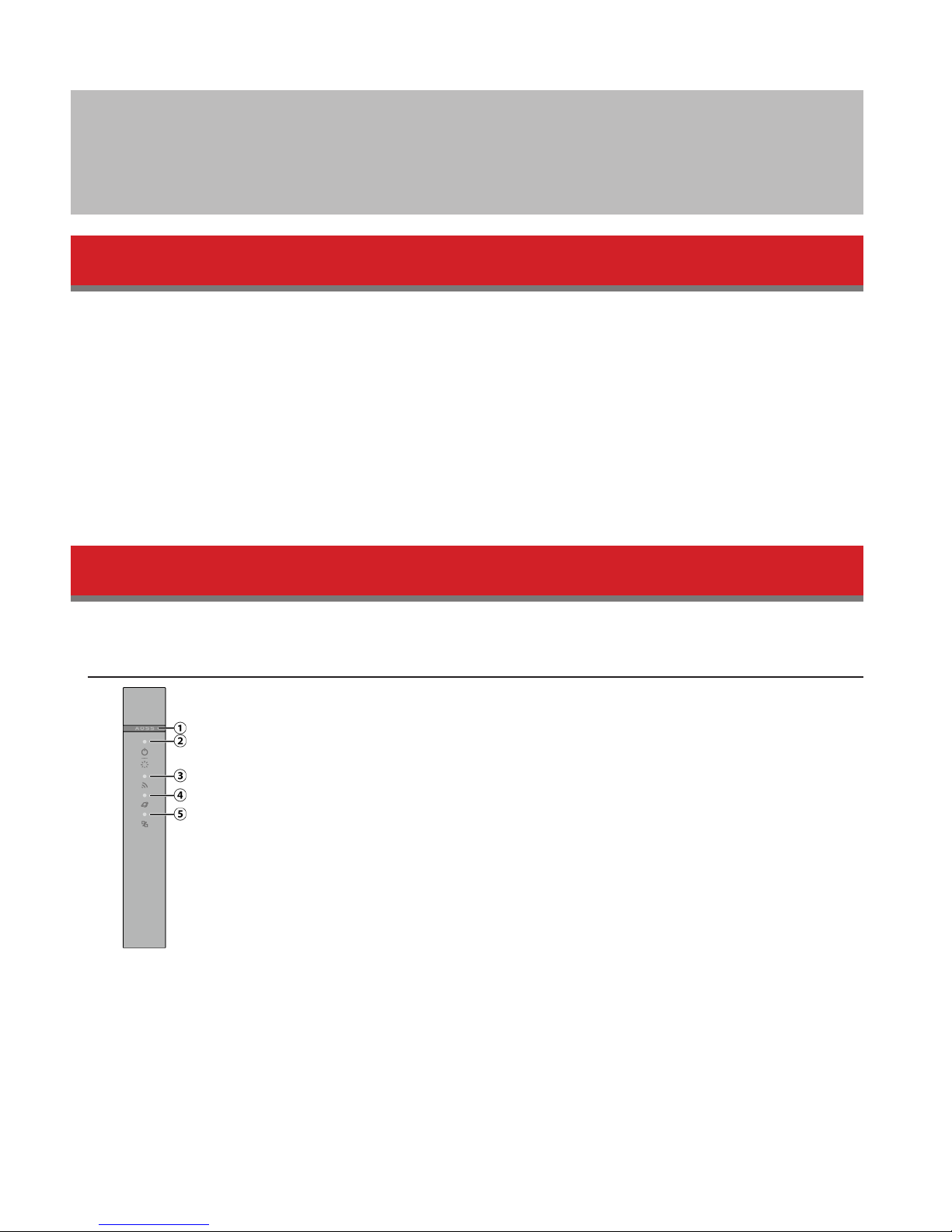
Front Panel
1 AOSS Button
To initiate AOSS, hold down this button until the wireless LED flashes (about 3 seconds). Then, push or click the
AOSS button on your wireless client device to complete the connection. Both devices must be powered on for this
to work.
6

2 Power / Diag LED (Green or Red)
On (Green):
Power is on.
Blinking (Green):
Booting.
Off:
Power is off.
2 blinks (Red)**:
Flash ROM error.
3 blinks (Red)**:
Wired LAN error.
4 blinks (Red)**:
Wireless LAN error.
5 blinks (Red)***:
IP address setting error.
Continuously blinking*:
Updating firmware, saving settings or initializing settings.
* Do not unplug the AC adapter while the LED is blinking continuously.
** Turn off AirStation first, wait for a few seconds, then turn it back on.
*** Cannot communicate because WAN-side and LAN-side IP addresses are same. Change LAN-side IP address of the
AirStation.
3 Wireless LED (Green or Amber)
On:
Wireless LAN is enabled or transmitting.
Double blinks:
AirStation is waiting for an AOSS or WPS security key.
Continuously blinking:
AOSS/WPS error; failed to exchange security keys.
Off:
Wireless LAN is disabled.
Note: For WHR-300HP2, the wireless LED will be green if security is enabled or amber if it is disabled. For WHR-600D,
the wireless LED will be green if security for both 2.4 GHz and 5 GHz is enabled or amber if either is disabled.
4 Internet Access LED (Green)
On:
Router functionality is enabled and you can connect to the Internet.
Blinking:
Router functionality is enabled but you cannot connect to the Internet.
Off:
Router functionality is disabled (the AirStation is in bridge mode).
5 Router LED (Green or Amber)
On (Green):
Mode switch is in the “Router” position.
On (Amber):
Mode switch is in the “Auto” position.
Off:
Mode switch is in the “Bridge” position.
7

Back Panel
1 Mode Switch
This switch changes between router mode and bridge (access point) mode. Auto mode will enable or disable
router functionality automatically.
2 LAN Port
Connect your computer, hub, or other Ethernet devices to these ports. This switching hub supports 10 Mbps and
100 Mbps connections.
3 Internet Port
10 Mbps and 100 Mbps connections are supported.
Note: In bridge (access point) mode, the Internet port becomes a regular LAN port, for a total of 5 usable LAN ports.
4 Reset Button
To reset all settings, hold down this button until the power/diag LED turns red (about 3 seconds). The power must
be on for this to work.
5 DC Connector
Connect the included AC adapter here.
8
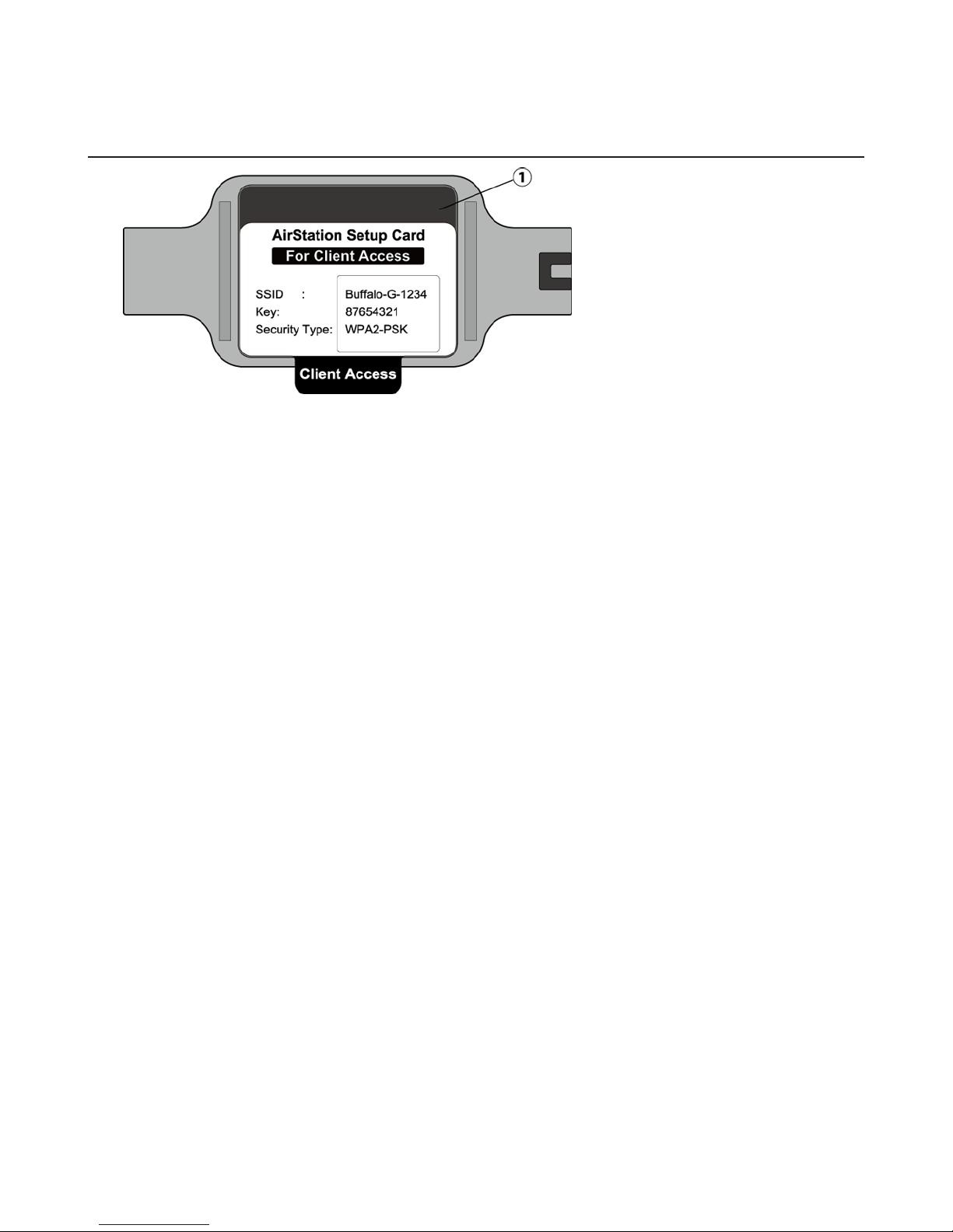
Bottom
1 Setup Card Slot
This is the slot where the AirStation setup card is stored. The initial settings for the username, password, SSID, and
encryption type are provided on the card.
9
Chapter 2 - Installation
Initial Setup
To configure your AirStation, follow the procedure below.
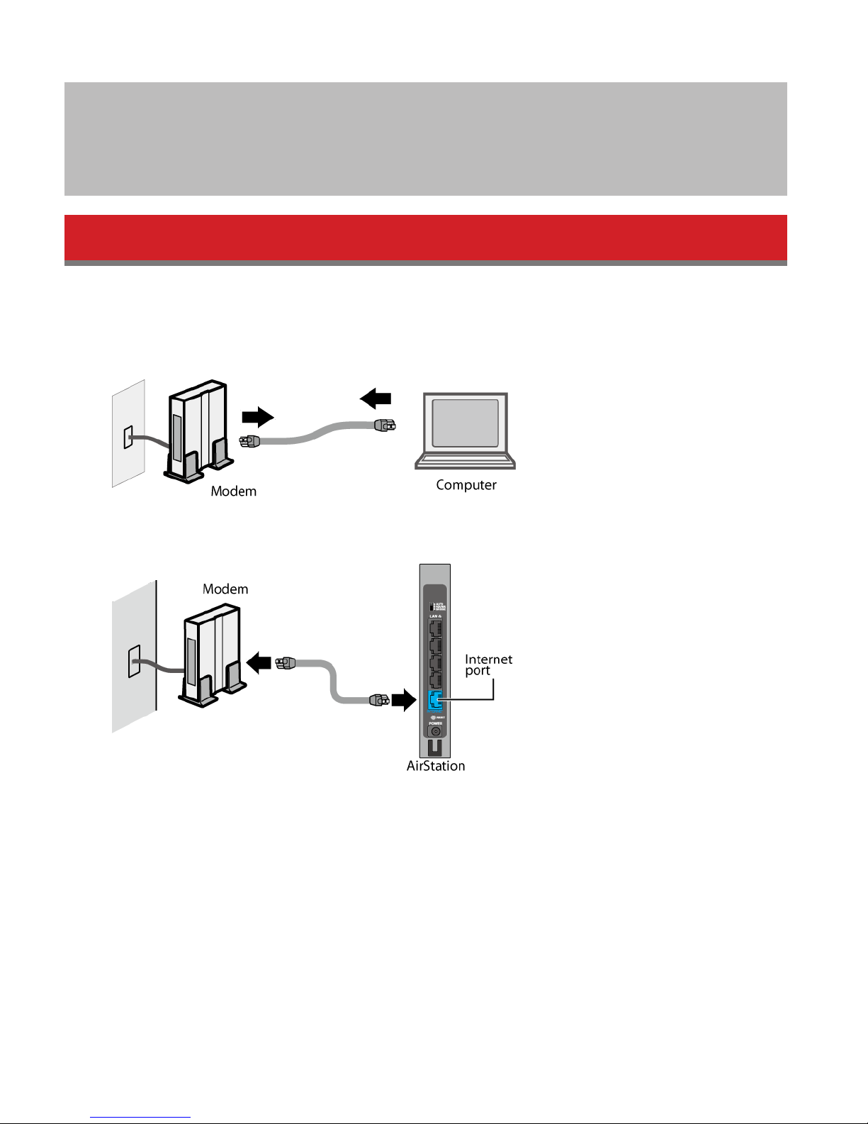
1 Verify that you can connect to the Internet without the AirStation, then turn off your modem and computer.
2 Unplug the LAN cable which connects your computer and modem.
3 Confirm that the mode switch is in the “Auto” position. Plug one end of the LAN cable into your modem and the
other end to the AirStation’s Internet (WAN) port. Turn on the modem.
10
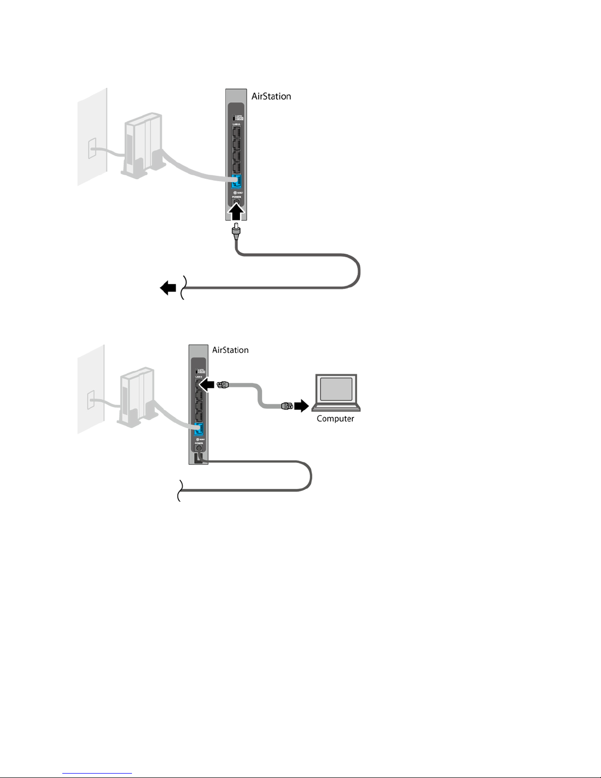
4 Turn on the AirStation and wait one minute.
5 If using a wired LAN, connect the AirStation LAN port and computer using a LAN cable.
If using a wireless LAN, connect the computer to the wireless LAN as described in chapter 4.
6 Once your computer has booted, the AirStation’s LEDs should be lit as described below:
Power/Diag: Green LED on.
Wireless: Green LED on.
Router: Amber LED on.
For LED locations, refer to chapter 1.
Note: If the router LED is not lit, set the mode switch to “Router”.
7 Launch a web browser. If the home screen is displayed, setup is complete.
If username and password fields are displayed, enter “admin” for the username and “password” for the password,
then click OK. Step through the wizard to complete setup.
You’ve completed the initial setup of your AirStation. Refer to chapter 3 for advanced settings.
11
Chapter 3 - Configuration
Configuration of the AirStation is done from Settings, the web-based configuration GUI. This user manual shows
Settings screens of WHR-600D as example.
Accessing Settings
To configure the AirStation’s settings manually, log in to Settings as shown below.
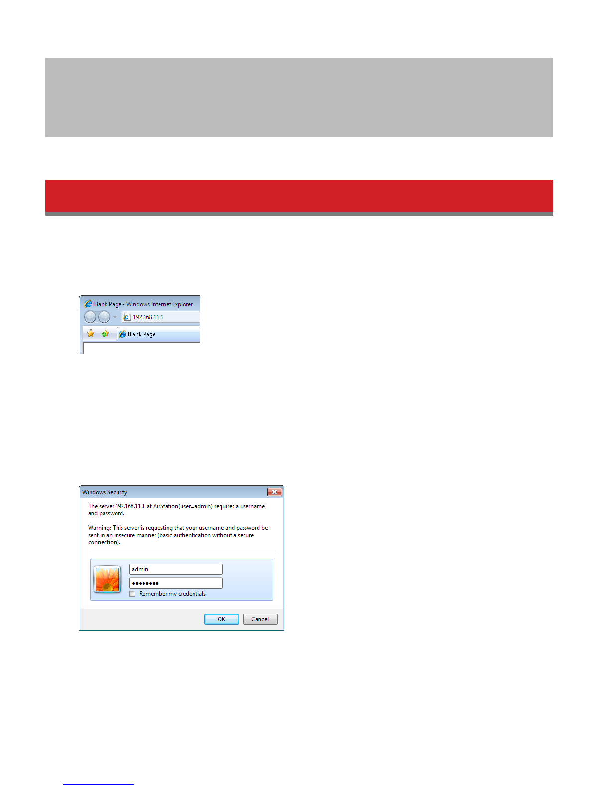
1 Open a browser.
2 Enter the AirStation’s LAN-side IP address in the address field and press the enter key.
Notes:
• The AirStation’s default LAN-side IP address depends on the mode.
In router mode: 192.168.11.1
In bridge (access point) mode: 192.168.11.100
If the mode switch is set to Auto and the AirStation is in bridge (access point) mode, the AirStation’s IP address is
assigned by an external DHCP server.
• If you changed the IP address of the AirStation, then use the new IP address.
3 Enter “admin” for the username and “password” for the password, then click OK.
Note: If you forget your password, hold down the reset button to initialize all settings. Note that all other settings
will also revert to their default values.
12
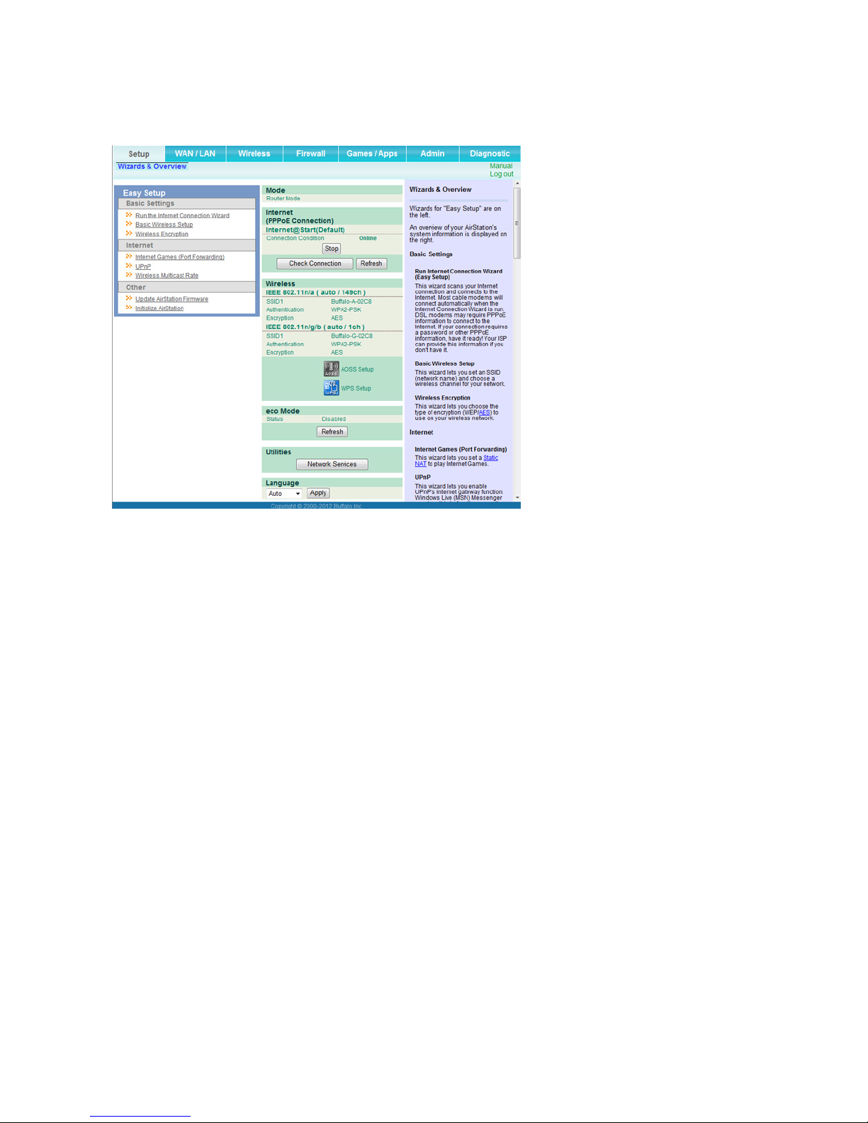
4 This is Settings, where most AirStation settings can be configured. Help is always displayed on the right side of
each screen. Refer to the help screens for more information on using Settings.
13
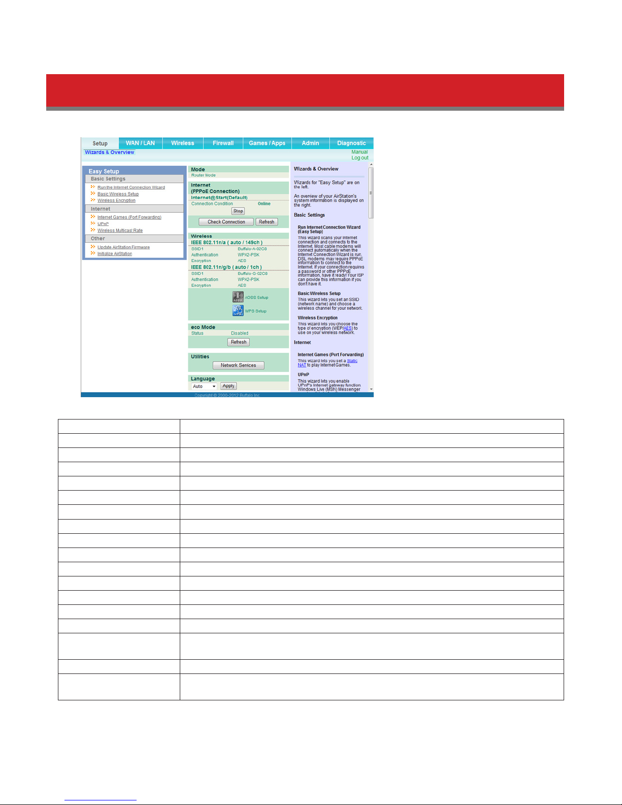
Setup
Setup is the home page of Settings. You can verify settings and the status of the AirStation here.
WAN / LAN Displays the configuration screen for the Internet port and LAN ports.
Wireless Displays the configuration screen for wireless settings.
Firewall Displays the configuration screen for the firewall.
Games / Apps Displays the configuration screen to open ports for games and applications.
Admin Displays the configuration screen for administration settings.
Diagnostic Displays the status of the AirStation.
Easy Setup Enables you to easily configure the AirStation’s network settings automatically.
Mode This indicates the operation mode of the AirStation.
Internet Displays WAN-side system information for the AirStation.
Check Connection Click to check if the AirStation is connected to the Internet properly.
Refresh Click to refresh the current screen.
Wireless Displays the current wireless settings.
AOSS Setup Click to display the AOSS configuration screen.
WPS Setup Click to display the WPS configuration screen.
eco Mode Displays current eco Mode status.
Network Services
Language Enables you to select the language you use.
Log Out
Displays the list of the network devices for which information is provided from the
network on the LAN-side.
Log out of Settings. If the AirStation does not communicate for 5 minutes, it will log out
automatically.
14
WAN / LAN
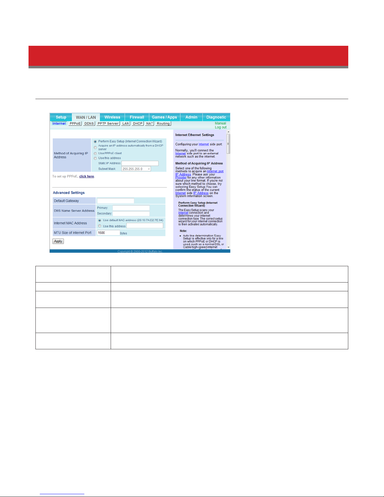
Internet
Configure the WAN-side port (“Internet port”) here. This function is only available when the AirStation is in router mode.
Method of Acquiring IP
Address
Default Gateway Configure an IP address for the default gateway.
DNS Name Server
Address
Internet MAC Address
MTU Size of Internet
Port
Specify how the WAN-side IP address is obtained.
Specify an IP address for the DNS server.
You may use the default MAC address or specify one manually.
Note: Configuring an improper MAC address may make the AirStation unusable. Do not
change the MAC address unless you know what you’re doing!
Configure the MTU (maximum transmission unit) value of the Internet port. Values of
578 to 1500 bytes may be entered.
15
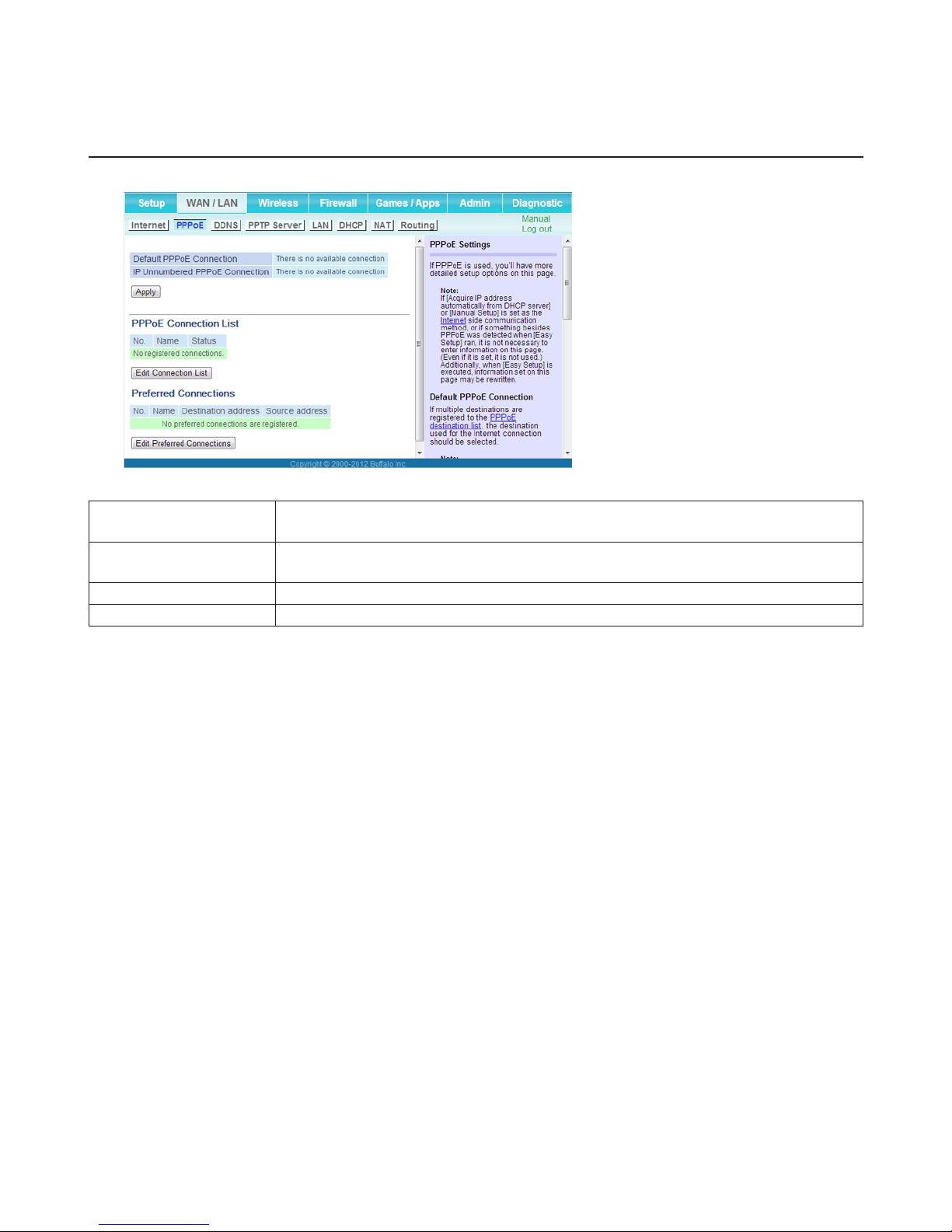
PPPoE
Configure PPPoE settings here. This function is only available when the AirStation is in router mode.
Default PPPoE
Connection
IP Unnumbered PPPoE
Connection
PPPoE Connection List Edit PPPoE destination. You can register up to 5 sessions.
Edit Connection List Click this button to edit destination settings.
If you have registered multiple connection destinations in the PPPoE Connection List,
connection destinations selected here have priority.
Select the destination from the PPPoE Connection List to be used when Use IP
Unnumbered is chosen as the method of acquiring IP address.
16

Name of Connection
Enter the name to identify the connected destination. You may enter up to 32
alphanumerical characters and symbols.
Username
Enter the username specified by your ISP for PPPoE certification. You may enter up to 64
alphanumerical characters and symbols.
Password
Enter the password specified by your ISP for PPPoE certification. You may enter up to 64
alphanumerical characters and symbols.
Service Name
Fill in this field only if your ISP specifies a service name. Leave blank otherwise. You may
enter up to 64 alphanumerical characters and symbols.
Connection Type
Select the connection method used by the AirStation to connect to your ISP.
PPPoE Connection
Automatic Disconnection
Set time to disconnect after communication is stopped when the connection method is
set to Connection on demand or Manual. You can enter up to 1440 minutes.
Authentication
Choose the type of authentication specified by your ISP.
MTU Size
Choose the MTU (maximum transmission unit) size recommended by your ISP. Values of
578 to 1492 bytes may be entered.
MRU Size
Choose the MRU (maximum receive unit) size recommended by your ISP. Values of 578
to 1492 may be entered.
Keepalive
If keepalive is enabled, the AirStation will issue an LCP echo request once a minute in
order to maintain the connection with the PPPoE server. If the server does not respond
for more than 6 minutes, the line is recognized as disconnected and the AirStation will
terminate the connection.
Preferred Connections Displays information you have set regarding to the connection destination route.
Edit Preferred
Connections
Click to edit the connection destination route settings.
Click Edit Preferred Connections to display.
Name
The destination to connect by PPPoE if Destination Address and Source Address match.
Preferred PPPoE
Connection
Select the destination registered to the PPPoE Connection List.
Destination Address
When communicating to this address, the AirStation will communicate with Name.
Source Address
When communicating from this address, the AirStation will communicate with Name.
17
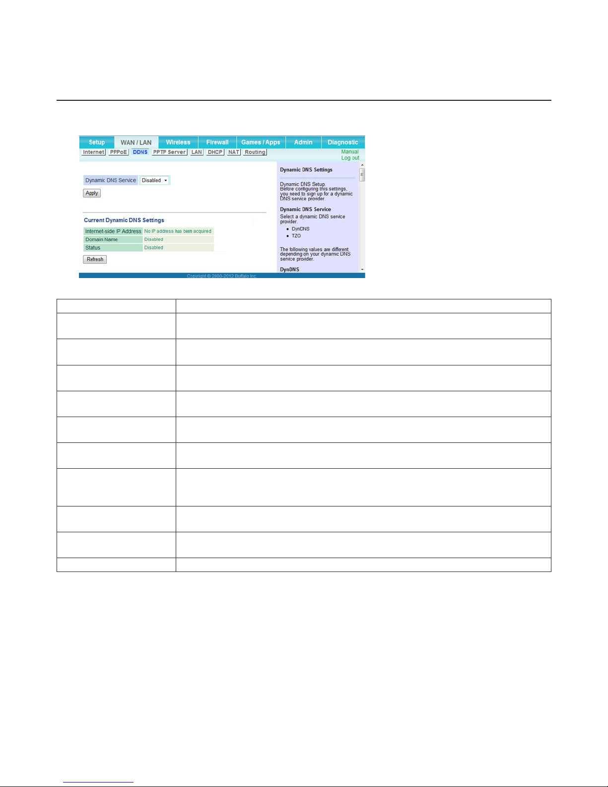
DDNS
Configure dynamic DNS settings here. Many settings are only available when the appropriate dynamic DNS service is
enabled. This function is only available when the AirStation is in router mode.
Dynamic DNS Service Select a provider (DynDNS or TZO) for dynamic DNS.
Username
Password
Hostname
Email Address
TZO Key
Domain Name
IP Address Update
Period
Internet-side IP Address
Domain Name
Status Displays the status of the dynamic DNS service.
Enter the dynamic DNS username. You may enter up to 64 alphanumerical characters
and symbols.
Enter the dynamic DNS password. You may enter up to 64 alphanumerical characters
and symbols.
Enter the dynamic DNS hostname. You may enter up to 255 alphanumerical characters,
hyphens, and periods.
Enter the email address that is registered to the dynamic DNS service. You may enter up
to 64 alphanumerical characters and symbols.
Enter the TZO Key that is registered to the dynamic DNS service. You may enter up to 64
alphanumerical characters and symbols.
Enter the domain name that is registered to the dynamic DNS service. You may enter up
to 255 alphanumerical characters, hyphens, and periods.
Specifies the period to notify the dynamic DNS service provider of the current IP
address. For DynDNS, set it between 0 and 35 days. For TZO, set it between 0 and 99
days. If 0 (zero) days is set, no periodic update is performed.
The WAN-side IP address of the AirStation’s Internet port. This address is sent to the
dynamic DNS service provider.
The domain name assigned by the dynamic DNS service provider. The AirStation can be
accessed from the Internet using this domain name.
18
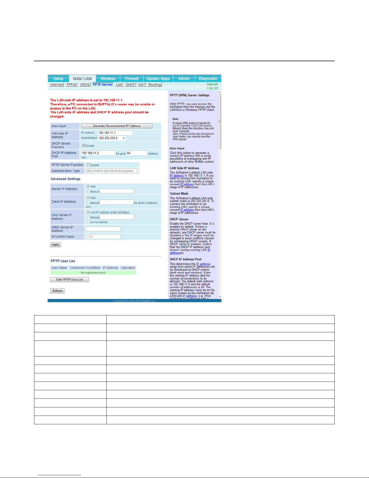
PPTP Server
Configure the PPTP server here. This function is only available when the AirStation is in router mode.
Auto Input Click to generate a random IP address.
LAN-side IP Address Set a LAN-side IP address and subnet mask.
DHCP Server Function Enable or disable the DHCP server, which assigns IP addresses automatically.
DHCP IP Address Pool
PPTP Server Function Enable to use a PPTP server.
Authentication Type Select the authentication method for PPTP connection.
Server IP Address Select the server IP address.
Client IP Address Select the IP address range.
DNS Server IP Address Choose the IP address for the DNS server.
WINS Server IP Address Choose the IP address for the WINS server.
MTU/MRU Value MTU/MRU values from 578 to 1500 are supported.
Edit PPTP User List Click to edit user information.
Configure the range of IP addresses to be assigned by the DHCP server and IP addresses
to be excluded from that range. Values from 1-256 may be entered.
19
Click Edit PPTP User List to display.
Username
Enter the username to connect to the PPTP server. You may enter up to 16
Add New User
Advanced Settings
PPTP User List Displays the PPTP connection user information.
alphanumerical characters and symbols.
Password
Enter the password to connect to the PPTP server. You may enter up to 16
alphanumerical characters and symbols.
Click Edit PPTP User List to display.
Method of Acquiring IP Address
Select the method to be used to assign the IP address for the PPTP client.
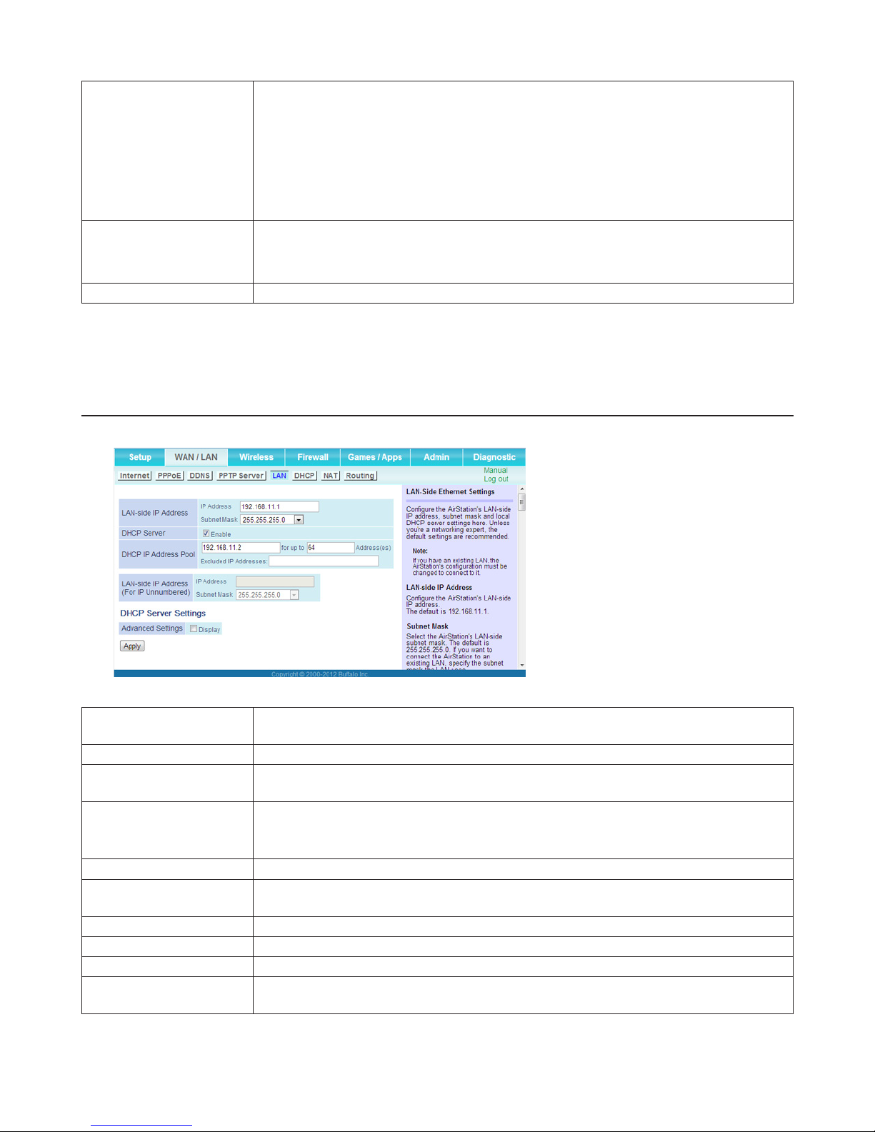
LAN
Configure LAN-side and DHCP server settings here.
LAN-side IP Address
DHCP Server Enable or disable the DHCP server, which assigns LAN-side IP addresses automatically.
DHCP IP Address Pool
LAN-side IP Address (For
IP unnumbered)
Advanced Settings Check Display to show additional settings for the DHCP server.
Lease Period
Default Gateway Set the default gateway IP address for the DHCP server to issue to clients.
DNS Servers Set the DNS server IP address for the DHCP server to issue to clients.
WINS Server Set the WINS server IP address for the DHCP server to issue to clients.
Domain Name
By default, the LAN-side IP address is 192.168.11.1 with subnet mask 255.255.255.0. You
may change it here.
Configure the range of IP addresses to be assigned by the DHCP server and IP addresses
to be excluded from that range. Values from 1-256 may be entered.
Set an IP unnumbered LAN-side IP address.
Note: A PC with a normal LAN-side IP address and a PC with an IP unnumbered IP
address cannot communicate with each other.
Set the effective period of an IP address assigned by the DHCP server. Up to 999 hours
may be entered.
Set the domain name for the DHCP server to issue to clients. You may enter up to 64
alphanumerical characters, hyphens, and periods.
20
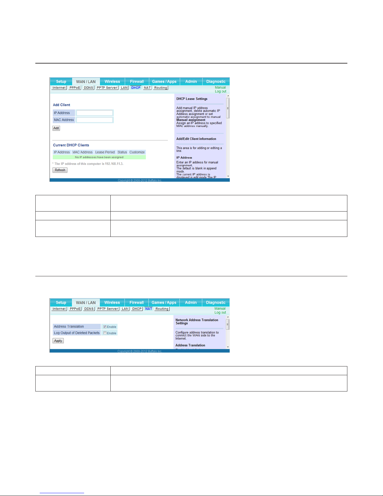
DHCP
Configure DHCP settings here. This function is only available when the AirStation is in router mode.
IP Address
MAC Address Enter the MAC address of the client.
Current DHCP Clients
Enter an IP address to lease manually. The IP address should be from the same subnet as
the DHCP scope, but not be within the range that DHCP is assigning to other devices.
Displays information for current leases. Click Edit to edit the entry and click Delete to
delete the entry.
NAT
Configure network address translation settings here. This enables LAN-side devices to communicate with the Internet.
This function is only available when the AirStation is in router mode.
Address Translation Enable to use network address translation (NAT).
Log Output of Deleted
Packets
Enable to log deleted packets (such as errors) during address translation.
21
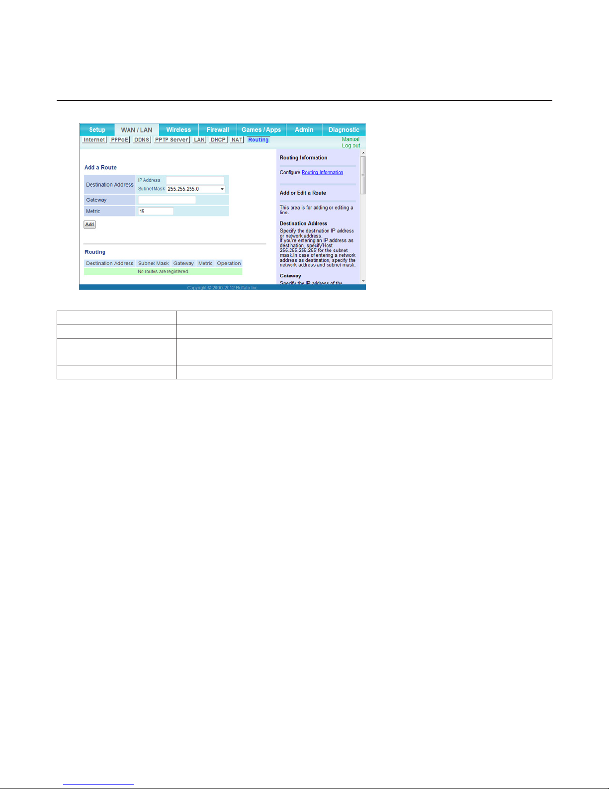
Routing
Configure the AirStation’s IP communication route here.
Destination Address Adds a destination IP address and subnet mask to the routing table.
Gateway Adds a gateway address to the routing table.
Metric
Routing Manual entries will appear here after being added.
The metric is the maximum number of router hops a packet may take on the way to its
destination address. Values between 1 and 15 may be entered. The default value is 15.
22
Wireless
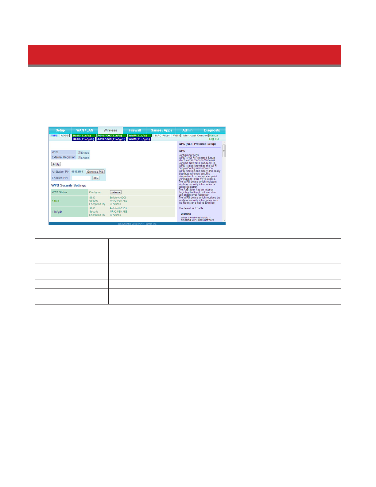
WPS
WPS is a system for configuring your wireless network automatically. WPS was created by the Wi-Fi Alliance. If your
wireless devices support WPS, you may connect them by pushing buttons on the devices or by entering a PIN from one
device into another.
WPS Enable to use WPS automatic configuration.
External Registrar
AirStation PIN
Enrollee PIN Enter the PIN code for the other wireless device and click OK.
WPS Status
Enable to accept configure requests from other WPS devices.
Note: Configure requests will not be accepted if AOSS is in use.
Displays the PIN code of the AirStation. Clicking Generate PIN will generate a new PIN
code. This code can be entered into other wireless devices that support WPS.
Displays “configured” if all available wireless bands are configured. Displays
“unconfigured” if a wireless band is unconfigured.
23
 Loading...