

Page 1
User Manual
Wireless AC1300 / N900 Gigabit Dual Band Router
WZR-D1800H
www.bualotech.com
Page 2

Contents
Chapter 1 - Product Overview .........................................5
Package Contents ................................................................... 5
Hardware Overview
Front Panel LEDs ........................................................................... 6
Back Panel
Bottom
Right Side
..................................................................................... 8
............................................................................................ 9
...................................................................................... 10
................................................................. 6
Vertical Placement .................................................................. 11
Horizontal Placement
Wall-Mounting
......................................................................... 12
.............................................................. 11
Chapter 2 - Installation ..................................................... 13
Initial Setup ............................................................................. 13
Chapter 3 - Conguration ................................................16
Accessing the Web-based Conguration Interface ................. 16
Conguration Interface Menus in Router Mode
Conguration Interface Menus in Bridge Mode
Setup
Internet/LAN (LAN Cong)
....................................................................................... 22
...................................................... 24
Internet (Router Mode only) ........................................................... 24
PPPoE (Router Mode only)
DDNS (Router Mode only)
VPN server (Router Mode Only)
LAN
................................................................................................ 32
DHCP Lease (Router Mode only)
NAT (Router Mode only)
Route
............................................................................................. 36
............................................................ 25
............................................................. 28
.................................................... 30
.................................................. 34
................................................................ 35
- 1 -
...................... 18
....................... 20
Page 3

Wireless Cong ....................................................................... 37
WPS ............................................................................................... 37
Basic
Advanced
WMM
MAC Filter
Multicast Control
AOSS
.............................................................................................. 38
....................................................................................... 41
.............................................................................................. 42
...................................................................................... 44
............................................................................ 45
............................................................................................. 46
Security (Router Mode only) ................................................... 47
Firewall (Router Mode only) ........................................................... 47
IP Filter (Router Mode only)
VPN Passthrough (Router Mode only)
........................................................... 49
........................................... 50
LAN Cong .............................................................................. 51
Port Forwarding (Router Mode only) .............................................. 51
DMZ (Router Mode only)
UPnP (Router Mode only)
QoS (Router Mode only)
............................................................... 52
.............................................................. 53
................................................................ 54
NAS ......................................................................................... 55
Disk management .......................................................................... 55
Shared Folder
User Management
Shared Service
Web Access
Media Server
BitTorrent
................................................................................ 57
......................................................................... 59
.............................................................................. 60
................................................................................... 61
.................................................................................. 63
........................................................................................ 64
Admin Cong ........................................................................... 66
Name ............................................................................................. 66
Password
Time/Date
NTP
................................................................................................ 69
ECO
Network-USB
............................................................................................... 70
....................................................................................... 67
...................................................................................... 68
................................................................................. 71
Access
........................................................................................... 72
- 2 -
Page 4

Log ................................................................................................. 73
Save/Restore
Initialize/Restart
Update
........................................................................................... 76
................................................................................. 74
............................................................................. 75
Diagnostic ............................................................................... 78
System Info .................................................................................... 78
Logs
Packet Info
Client Monitor
Ping
............................................................................................... 80
..................................................................................... 81
................................................................................. 82
................................................................................................ 83
Chapter 4 - Connect to a Wireless Network ................... 84
Automatic Secure Setup (AOSS / WPS) ................................. 84
Windows 7/Vista (Client Manager V) ............................................. 85
Windows XP (Client Manager 3)
.................................................... 86
Mac OS X (AOSS Assistant)
Other Devices (e.g. Game Console)
.......................................................... 87
.............................................. 88
Manual Setup .......................................................................... 88
Windows 7 (WLAN AutoCong) ..................................................... 88
Windows Vista (WLAN AutoCong)
Windows XP (Wireless Zero Conguration)
Mac OS X (Wi-Fi)
........................................................................... 93
............................................... 89
................................... 92
Chapter 5 - Troubleshooting ............................................94
Cannot connect to the Internet over wired connection. ........... 94
Cannot access the web-based conguration Interface.
Cannot connect to the network wirelessly.
.............................. 95
You forgot AirStation's SSID, Encryption Key, or Password.
Restoring the Default Conguration
........................................ 95
.......... 94
... 95
TCP/IP Settings (Windows 7)
.................................................. 96
TCP/IP Settings (Windows Vista)
TCP/IP Settings (Windows XP)
............................................... 98
- 3 -
............................................ 97
Page 5

TCP/IP Settings (Mac OS X) ................................................... 99
Other Tips
................................................................................ 100
Chapter 6 - Default Conguration Settings .................... 102
Chapter 7 - Network-USB Navigator
Initial Setup for Windows Users .............................................. 109
Initial Setup for Mac Users
Opening the Network-USB User Manual
How to use Network-USB
...................................................... 114
....................................................... 118
...............................109
................................ 117
Chapter 8 - Checking Wireless Signal Quality ............... 119
Windows 7/Vista ...................................................................... 119
Mac OS X
................................................................................ 120
Chapter 9 - Shared Folders and the USB Port ............... 122
- 4 -
Page 6

Chapter 1 - Product Overview
Package Contents
The following items are included in your AirStation package. If any of the items are missing, please
contact your vender.
• WZR-D1800H ................................................................................................................................1
• AirStation Setup Card ................................................................................................................ 1
• AC adapter .....................................................................................................................................1
• Stands .............................................................................................................................................. 2
• Screws for wall-mounting ........................................................................................................ 2
• LAN cable .......................................................................................................................................1
• AirNavigator CD ...........................................................................................................................1
• Quick Setup Guide ...................................................................................................................... 1
• Warranty Statement ...................................................................................................................1
- 5 -
Page 7
Chapter 1 Product Overview
Hardware Overview
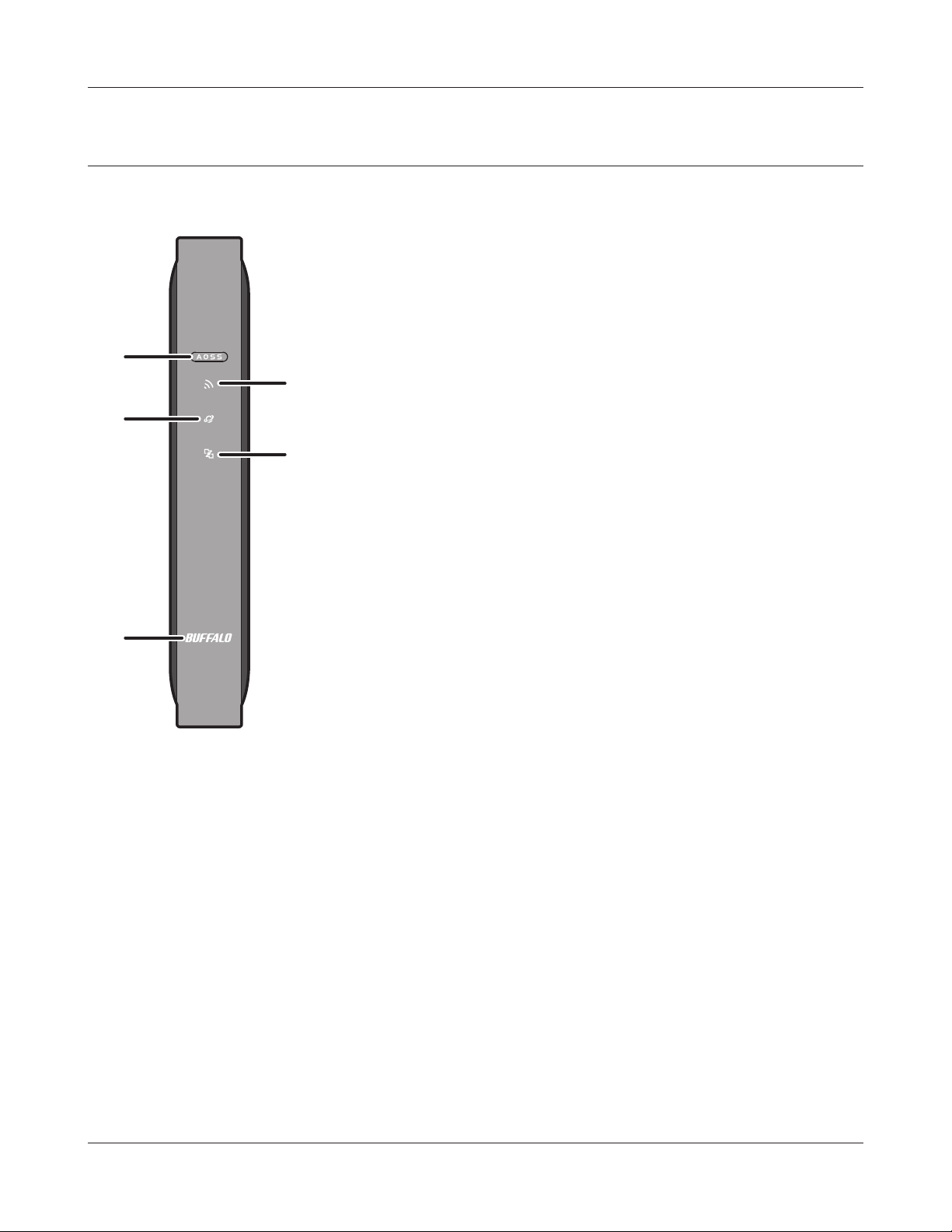
Front Panel LEDs
1
2
3
4
5
1
AOSS button To initiate AOSS, hold down this button until the Wireless LED ashes
(about 1 second). Then, push or click the AOSS button on your wireless
client device to complete the connection. Both devices must be powered
on for this to work.
2
Wireless LED (Blue or Amber)
On: Wireless LAN is enabled.
Randomly blinking: Wireless LAN is transmitting.
2 blinks: AirStation is waiting for an AOSS or WPS security key.
Continuously
blinking:
O: Wireless LAN is disabled.
Note:
Wireless LED is blue : Security settings have been made for the wireless LAN.
Wireless LED is amber : Security settings have not been made for the wireless LAN.
AOSS/WPS error; failed to exchange security keys.
- 6 -
Page 8

Chapter 1 Product Overview
3
Internet access LED (Blue)
On: Internet access is available.
O: Internet access is not available.
4
Router LED (Blue)
On: Router functionality is enabled.
O: Router functionality is disabled.
5
Bualo LED (White or Red)
On (White): Power is on.
O: Power is o.
*1
On (Red)
2 blinks (Red)
3 blinks (Red)
4 blinks (Red)
5 blinks (Red)
9 blinks (Red)
: Booting.
*2
: Flash ROM error.
*2
: Wired Ethernet LAN error.
*2
: Wireless LAN error.
*3
: IP address setting error.
*2
: System error.
Continuously
*1
blinking
*1 Never unplug the AC adapter while the Bualo LED is blinking continuously.
*2 Turn o AirStation rst, wait for a few seconds, then turn it back on.
*3 Because the network addresses of both the Internet port (WAN port) and the LAN port are the
:
same, it is not possible to establish communication. Change the LAN side IP address of the
AirStation.
Updating rmware, saving settings, or initializing settings.
- 7 -
Page 9
Chapter 1 Product Overview
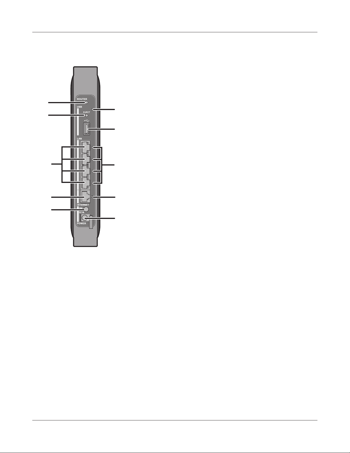
Back Panel
6
8
7
9
10
11
12
13
14
15
6
Router button This button turns the router on and o. The operation mode is changed
by holding down the button.
7
USB LED (Blue)
On: The USB drive is connected.
Blinking: The USB drive can be removed.
Note: When this LED is blinking, the connected USB drive cannot be used. Remove the connected USB
drive. If the LED continues to blink even after the USB drive is removed, restart the AirStation. Do
not remove the USB drive or turn o the AirStation while the USB LED is on.
8
USB Eject button To dismount a USB hard drive, hold down this button until the USB LED
ashes (about 3 seconds). The USB drive can then be unplugged safely.
9
USB Port Connect the USB drive.
- 8 -
Page 10
Chapter 1 Product Overview
10
LAN Port Connect your computer, hub, or other Ethernet devices to these ports.
This switching hub supports 10 Mbps,100 Mbps, and 1000 Mbps
connections.
11
Internet Port 10 Mbps, 100 Mbps, and 1000 Mbps connections are supported.
Note: In bridge/AP mode (router o), the Internet port becomes a
regular LAN port, for a total of 5 usable LAN ports.
12
LAN LED (Green)
On: An Ethernet device is connected.
Blinking: An Ethernet device is communicating.
13
Internet LED (Green)
On: The Internet port is connected.
Blinking: The Internet port is transmitting data.
14
Power button This button turns the power on and o.
15
DC connector Connect the included AC adapter here.
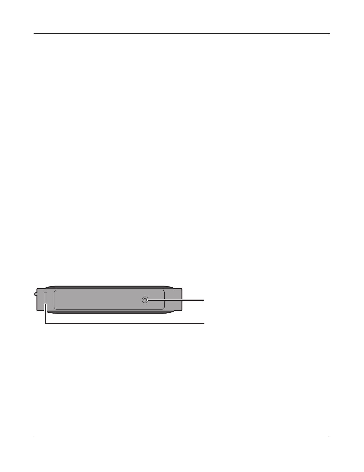
Bottom
16
17
16
Reset button To reset all settings, hold down this button until the Bualo LED turns red
(about 3 seconds). The power must be on for this to work.
17
Setup card slot This is the slot where the AirStation setup card is stored. The initial
settings for the username, password, SSID, and encryption type are
provided on the card for logging into the conguration interface.
- 9 -
Page 11
Chapter 1 Product Overview
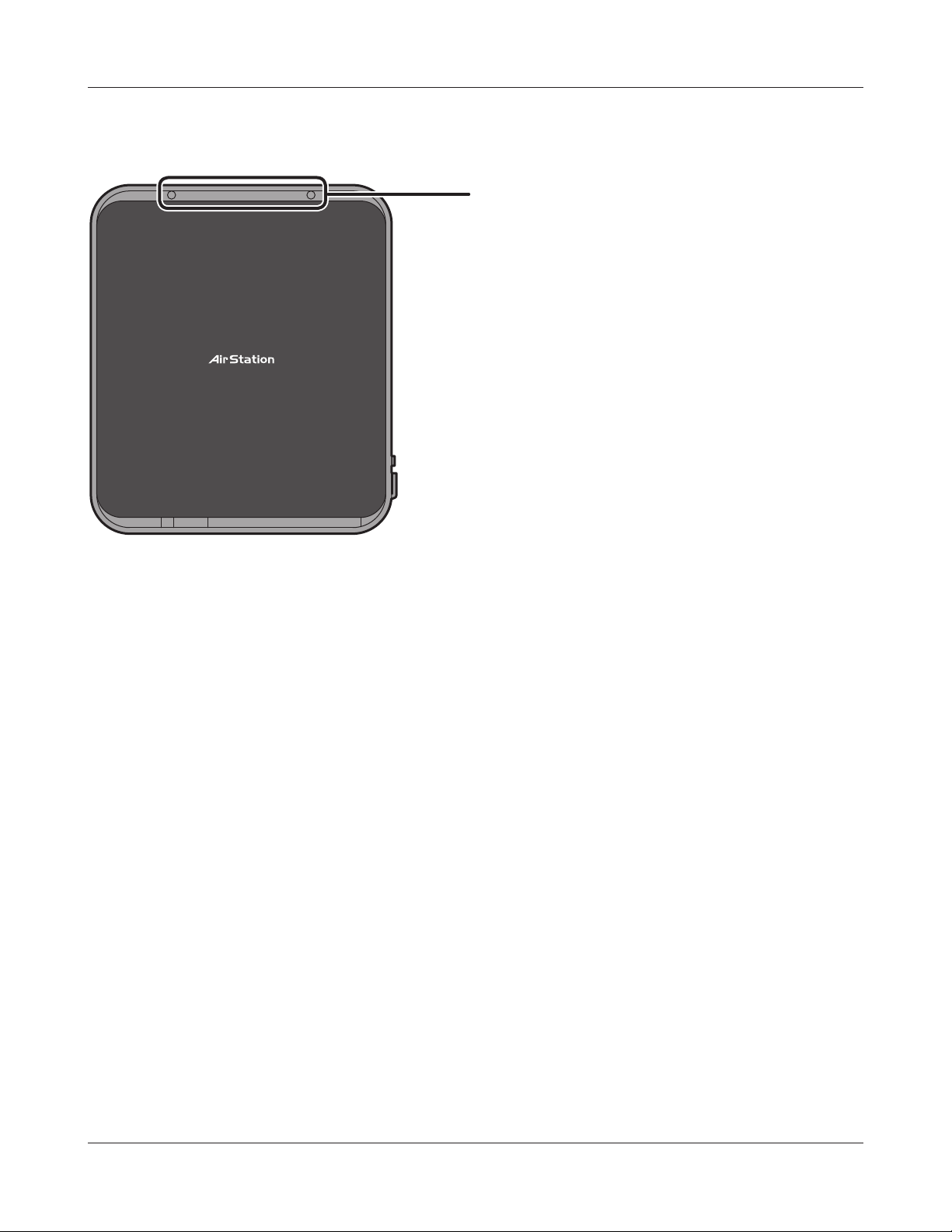
Right Side
18
18
Mounting holes Mounting holes are provided for mounting the AirStation to a
wall. Use the supplied screws in the holes to mount to a wall.
- 10 -
Page 12
Chapter 1 Product Overview
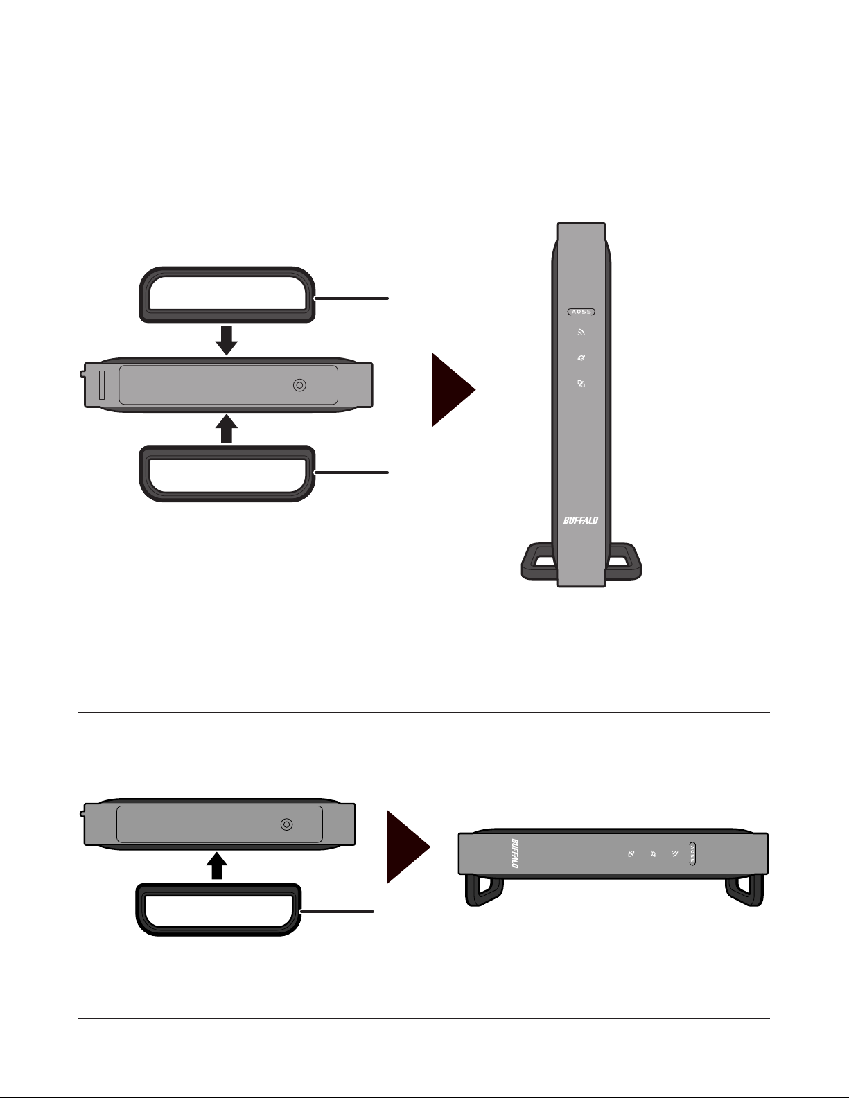
Vertical Placement
Attach the stand as shown in the gure below.
Stand
Stand
Horizontal Placement
The same stand also allows horizontal placement. Install the stand as shown in the gure below.
Stand
- 11 -
Page 13
Chapter 1 Product Overview
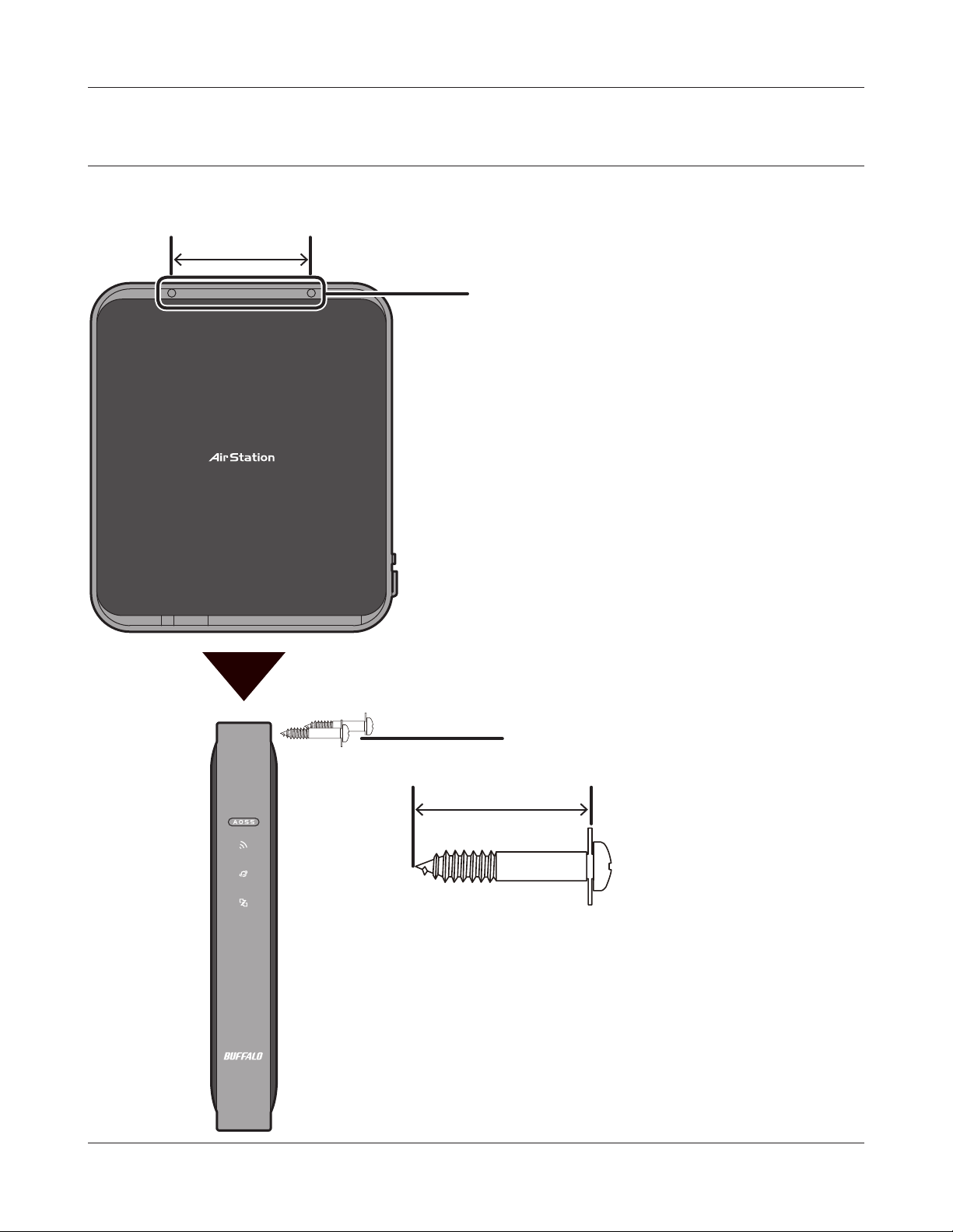
Wall-Mounting
Install with the supplied screws in the mounting holes of the AirStation as shown in the gure
below.
85 mm (3.35 in.)
Mounting holes
Screws
50 mm (1.97 in.)
- 12 -
Page 14
Chapter 2 - Installation
Initial Setup
To congure your AirStation, follow the procedure below.
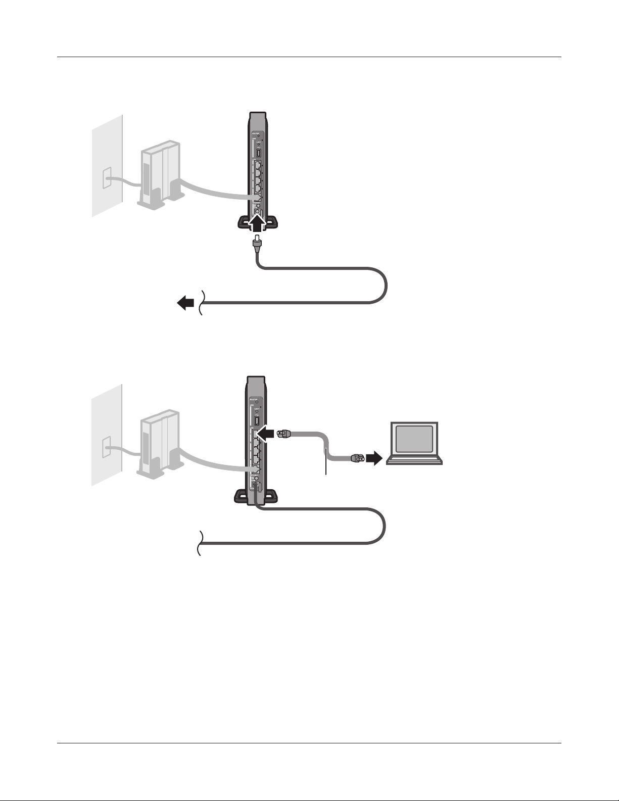
1
2
3
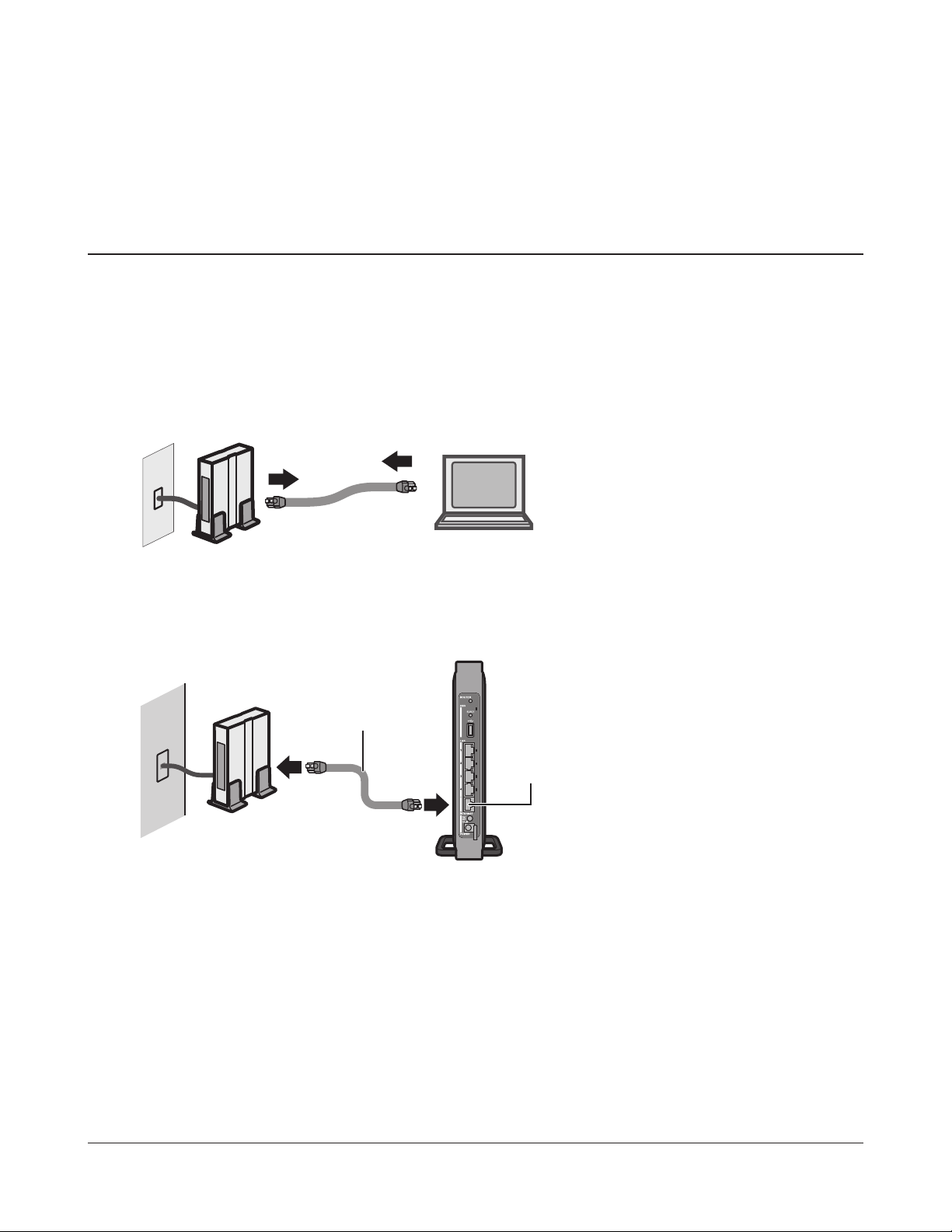
Verify that you can connect to the internet without the AirStation, then turn o your modem
and computer.
disconnect
Unplug the LAN cable which connects
your computer and modem.
modem computer
Plug one end of the LAN cable into your modem and the other end to the AirStation’s
Internet (WAN) port. Turn on the modem.
modem
LAN cable
1) connect
Internet
2) connect
port
AirStation
- 13 -
Page 15
Chapter 2 Installation
4
5
Turn on the AirStation, then wait one minute.
AirStation
Note : If the power does not turn on even when the AC
adapter is connected, press the Power button on
the rear of the AirStation.
Connect the power supply
power outlet
If using a wired LAN, connect the AirStation LAN port and computer using a LAN cable.
If using a wireless LAN, connect the computer to the wireless LAN by referring to Chapter 4.
AirStation
6
1) connect
LAN cable
2) connect
computer
Once your computer has booted, the AirStation’s LEDs should be lit as described below:
Wireless On or blinking.
Internet access On.
Router On.
Bualo White light on.
LAN Green light on or blinking.
Internet Green light on or blinking.
For LED locations, refer to chapter 1.
Note: If the router LED is not lit, hold down the router button for about 3 seconds to switch to
router mode.
- 14 -
Page 16

Chapter 2 Installation
7
Launch a web browser. If the home screen is displayed, setup is complete.
If username and password elds are displayed, enter “admin” for the username and
“password” for the password, then click [OK]. Step through the wizard to complete setup.
You’ve completed the initial setup of your AirStation. Refer to Chapter 3 for advanced
settings.
- 15 -
Page 17

Chapter 3 - Conguration
The web-based conguration tool lets you change advanced settings for the AirStation. Don’t
change these settings unless you know what you’re doing.
Accessing the Web-based Conguration Interface
To congure the AirStation’s advanced settings manually, log in to the web-based conguration
interface as shown below.
1
2
3
Launch a web browser.
Enter the AirStation’s LAN-side IP address in the
address eld and press the Enter key.
Note: The AirStation’s default LAN-side IP address depends on the mode.
In router mode: 192.168.11.1
In bridge mode: 192.168.11.100
If you changed the IP address of the AirStation, then use the new IP address.
Enter “admin” for the username and “password”
for the password and click [OK].
- 16 -
Note: If you forget your password, hold down the
Reset button (page 9) to initialize all settings.
Note that all other settings will also revert to
their default values.
Page 18
Chapter 3 Conguration
4
This is the conguration
interface, where most
AirStation settings can be
congured.
Help is always displayed on
the right side of each screen.
Refer to the help screens for
more information on using the
conguration interface.
- 17 -
Page 19

Chapter 3 Conguration
Conguration Interface Menus in Router Mode
The menu structure for the AirStation in router mode is as follows. Please refer to the pages listed at
right for explanations of each item.
Main screen Descriptions Page
Internet/LAN
Internet Congure Internet side port and settings. Page 24
PPPoE PPPoE settings (DSL login). Page 25
DDNS DNS settings. Page 28
VPN Server VPN server settings. Page 30
LAN LAN side port conguration. Page 32
DHCP Lease DHCP lease settings. Page 34
NAT Network address translation settings, used to connect LAN side devices
to the Internet.
Route Congure the AirStation’s IP communication route. Page 36
Wireless Cong
WPS WPS settings and status. Page 37
Basic Congure basic wireless settings. Page 38
Advanced Congure advanced wireless settings. Page 41
WMM Set priorities for Wireless Multimedia Extensions (Wi-Fi Multimedia). Page 42
MAC Filter Limit access to specic devices. Page 44
Multicast Control Congure limits on sending unnecessary multicast packets to the
wireless LAN port.
AOSS AOSS (AirStation One-touch Secure System) settings and status. Page 46
Security
Firewall Protect your computer from outside intruders. Page 47
IP Filter IP lters for packets passing through the LAN side and the Internet side. Page 49
VPN
Passthrough
LAN Cong
Congure IPv6 passthrough, PPPoE passthrough, and PPTP passthrough. Page 50
Page 35
Page 45
Port Forwarding Congure port translation and exceptions for games and other
programs.
DMZ Congure a destination to transfer communication packets without a
LAN side destination.
UPnP Congure UPnP (Universal Plug and Play). Page 53
QoS Congure priority for packets that require a guaranteed data ow. Page 54
- 18 -
Page 51
Page 52
Page 20

Chapter 3 Conguration
NAS
Disk Management View the status and congure of attached USB disks. Page 55
Shared Folder Set the USB disk to use as shared folders. Page 57
User Management Congure users to access shared folders. Page 59
Shared Service Congure shared folder access. Page 60
Web Access Congure Web Access. Page 61
Media Server Congure a Media Server. Page 63
BitTorrent Congure a BitTorrent client. Page 64
Admin Cong
Name Congure the AirStation’s name. Page 66
Password Congure the AirStation’s login password for access to the conguration
Page 67
interface.
Time/Date Congure the AirStation’s internal clock. Page 68
NTP Congure the AirStation to synchronize with an NTP server to
Page 69
automatically set the AirStation’s internal clock.
ECO Congure the AirStation’s ECO Mode. Page 70
Network-USB Congure Network-USB from this screen. Page 71
Access Congure access restrictions to the AirStation’s conguration interface. Page 72
Log Congure a syslog server to manage the AirStation’s logs. Page 73
Save/Restore Save or restore the AirStation’s conguration from a conguration le. Page 74
Initialize/Restart Initialize the AirStation or reboot it. Page 75
Update Update the AirStation’s rmware. Page 76
Diagnostic
System Info View current system information for the AirStation. Page 78
Logs Check the AirStation’s logs. Page 80
Packet Info View all packets transferred by the AirStation. Page 81
Client Monitor View all devices currently connected to the AirStation. Page 82
Ping Test the AirStation’s connection to other devices on the network. Page 83
Logout
Click this to log out of the AirStation’s conguration interface.
- 19 -
Page 21

Chapter 3 Conguration
Conguration Interface Menus in Bridge Mode
The menu structure in bridge mode is as follows. Please refer to the pages listed at right for
explanations of each item.
Main screen Descriptions Page
LAN Cong
LAN LAN side port conguration. Page 32
Route Congure the AirStation’s IP communication route. Page 36
Wireless Cong
WPS WPS settings and status. Page 37
Basic Congure basic wireless settings. Page 38
Advanced Congure advanced wireless settings. Page 41
WMM Set priorities for Wireless Multimedia Extensions (Wi-Fi Multimedia). Page 42
MAC Filter Limit access to specic devices. Page 44
Multicast Control Congure limits on sending unnecessary multicast packets to the
wireless LAN port.
AOSS AOSS (AirStation One-touch Secure System) settings and status. Page 46
NAS
Disk Management View the status and congure of attached USB disks. Page 55
Shared Folder Set the USB disk to use as shared folders. Page 57
User Management Congure users to access shared folders. Page 59
Shared Service Congure shared folder access. Page 60
Web Access Congure Web Access. Page 61
Media Server Congure a Media Server. Page 63
BitTorrent Congure a BitTorrent client. Page 64
Admin Cong
Name Congure the AirStation’s name. Page 66
Password Congure the AirStation’s login password for access to the conguration
interface.
Time/Date Congure the AirStation’s internal clock. Page 68
Page 45
Page 67
NTP Congure the AirStation to synchronize with an NTP server to
automatically set the AirStation’s internal clock.
ECO Congure the AirStation’s ECO Mode. Page 70
Network-USB Congure Network-USB from this screen. Page 71
Access Congure access restrictions to the AirStation’s conguration interface. Page 72
- 20 -
Page 69
Page 22

Chapter 3 Conguration
Log Congure a syslog server to manage the AirStation’s logs. Page 73
Save/Restore Save or restore the AirStation’s conguration from a conguration le. Page 74
Initialize/Restart Initialize the AirStation or reboot it. Page 75
Update Update the AirStation’s rmware. Page 76
Diagnostic
System Info View current system information for the AirStation. Page 78
Logs Check the AirStation’s logs. Page 80
Packet Info View all packets transferred by the AirStation. Page 81
Client Monitor View all devices currently connected to the AirStation. Page 82
Ping Test the AirStation’s connection to other devices on the network. Page 83
Logout
Click this to log out of the AirStation’s conguration interface.
- 21 -
Page 23

Chapter 3 Conguration
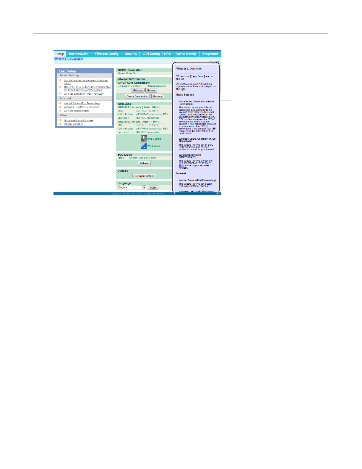
Setup
Setup is the home page of the conguration interface. You can verify settings and the status of the
AirStation here.
Parameter Meaning
Internet/LAN (LAN Cong) Displays the conguration screen for the Internet port and LAN
ports.
Wireless Cong Click this button to display the conguration screen for wireless
settings.
Security Click this button to display the conguration screen for security.
- 22 -
Page 24

Chapter 3 Conguration
Parameter Meaning
LAN Cong Click this button to display the conguration screen to open ports
for games and applications.
NAS Click this button to display the conguration screen for NAS
settings.
Admin Cong Click this button to display the conguration screen for
administration settings.
Diagnostic Click this button to display the status of the AirStation.
Easy Setup Enables you to easily congure the AirStation’s network settings
automatically.
MODE Information This indicates the operation mode of the AirStation.
Internet Information Displays WAN-side system information for the AirStation.
Check Connection Click this button to check if the AirStation is connected to the
Internet properly.
Refresh Click this button to refresh the current screen.
WIRELESS Displays the current wireless settings.
AOSS Setup Click this button to display the AOSS conguration screen.
WPS Setup Click this button to display the WPS conguration screen.
ECO Mode This indicates the operating status of ECO Mode.
Network Service List Displays the list of the network devices for which information is
provided from the network on the LAN-side.
Media Server Displays the status of the media server.
Download List Displays the list of BitTorrent les downloading.
Language Enables you to select the language you use.
Logout Log out of the conguration interface. If the AirStation does not
communicate for 5 minutes, it will log out automatically.
- 23 -
Page 25
Chapter 3 Conguration
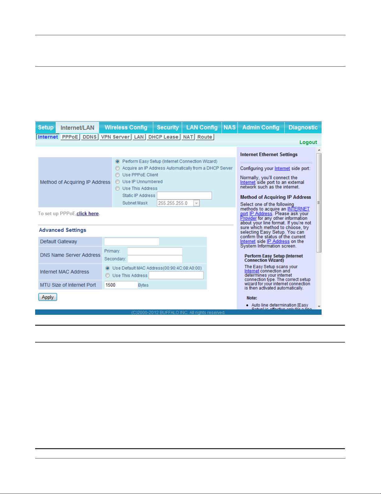
Internet/LAN (LAN Cong)
Internet (Router Mode only)
Congure the WAN-side port (“Internet port”).
Parameter Meaning
Method of Acquiring IP Address Specify how the WAN-side IP address is obtained.
Default Gateway Congure an IP address for the default gateway.
DNS Name Server Address Specify an IP address for the DNS server.
Internet MAC Address Congure the Internet side MAC address.
Note: Conguring an improper MAC address may make the AirStation
unusable. Change this setting at your own risk.
MTU size of Internet Port Congure the MTU value of the Internet port. Values of 578 to 1500
bytes may be entered.
- 24 -
Page 26

Chapter 3 Conguration
PPPoE (Router Mode only)
Congure PPPoE settings.
Parameter Meaning
Default PPPoE Connection If you have registered multiple connection destinations in the
PPPoE Connection List, connection destinations selected here
have priority. You need to congure the route to which PPPoE is
connected to if you don’t use the default settings.
IP Unnumbered PPPoE Connection Select the destination from the PPPoE Connection List which is
used when “Use IP Unnumbered” is chosen for the Method of
Acquiring IP Address (page 24).
PPPoE Connection List Edit PPPoE destination. You can register up to 5 sessions.
[Edit Connection List] Click this button to edit destination settings.
- 25 -
Page 27

Chapter 3 Conguration
Parameter Meaning
PPPoE Connection No.*-Add This is displayed when [Edit Connection List] is clicked.
Name of Connection
Enter the name to identify the connected destination. You may
enter up to 32 alphanumerical characters and symbols.
Username
Enter the username specied by your ISP for PPPoE certication.
You may enter up to 32 alphanumerical characters and symbols.
Password
Enter the password specied by your ISP for PPPoE certication.
You may enter up to 32 alphanumerical characters and symbols.
Service Name
Fill in this eld only if your ISP species a Service Name. Leave
blank otherwise. You may enter up to 32 alphanumerical
characters and symbols.
Connection Type
Species the timing for the AirStation to connect to your
provider.
Automatic disconnection
Set time to disconnect after communication is stopped when
the connection method is set to [Connection on Demand] or
[Manual]. You can enter up to 1440 minutes.
Authorization
Congure an authorization method with a provider.
MTU Size
Congure the MTU size for PPPoE. Values of 578 to 1500 bytes
may be entered.
MRU Size
Congure MRU (Maximum Receive Unit) for PPPoE. Values of 578
to 1492 may be entered.
- 26 -
Page 28

Chapter 3 Conguration
Parameter Meaning
PPPoE Connection No. *-Add Keep Alive
If Keep Alive is enabled, then the AirStation will issue an LCP
echo request once a minute in order to maintain the connection
with the PPPoE. If the server does not respond for more than
6 minutes, the line is recognized as disconnected and the
AirStation will terminate the connection. [Disabled] is the
recommended setting.
Preferred Connections Displays information you have set regarding to the connection
destination route.
[Edit Preferred Connections] Click to edit the connection destination route settings.
Preferred PPPoE Connection -Add Click [Edit Preferred Connections] to display.
Name
The destination to connect by PPPoE if [Destination address] and
[Source address] match. Select the destination registered to the
PPPoE Connection List.
Destination address
When communicating to this address, the AirStation will
communicate with [Name of Connection.]
Source address
When communicating from this address, the AirStation will
communicate with [Name of Connection.]
- 27 -
Page 29
Chapter 3 Conguration
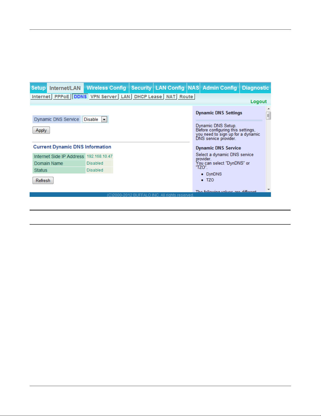
DDNS (Router Mode only)
Congure Dynamic DNS settings. Many settings are only available when the appropriate Dynamic
DNS service is enabled.
Parameter Meaning
Dynamic DNS Service Select a provider (DynDNS or TZO) for Dynamic DNS.
Username Enter the Dynamic DNS username. You may enter up to 64
alphanumerical characters and symbols.
Password Enter the Dynamic DNS password. You may enter up to 64
alphanumerical characters and symbols.
Hostname Enter the Dynamic DNS hostname. You may enter up to 255
alphanumerical characters, hyphens, and periods.
Email Address Enter the email address which is registered to the Dynamic DNS
service. You may enter up to 64 alphanumerical characters and
symbols.
TZO Key Enter the TZO Key which is registered to the Dynamic DNS service.
You may enter up to 64 alphanumerical characters and symbols.
Domain Name Enter the domain name which is registered to the Dynamic DNS
service. You may enter up to 255 alphanumerical characters,
hyphens, and periods.
- 28 -
Page 30

Chapter 3 Conguration
Parameter Meaning
IP Address Update Period Species the period to notify the dynamic DNS service provider of
the current IP address. For DynDNS, set it between 0 and 35 days.
For TZO, set it between 0 and 99 days. If 0 (zero) days is set, no
periodic update is performed.
Internet Side IP Address The WAN-side IP address of the AirStation’s Internet port. This
address is sent to the dynamic DNS service provider.
Domain Name The domain name assigned by the dynamic DNS Service provider.
The AirStation can be accessed from the Internet using this domain
name.
Status Display the status of dynamic DNS service.
- 29 -
Page 31

Chapter 3 Conguration
VPN server (Router Mode Only)
Congure the VPN server.
- 30 -
Page 32

Chapter 3 Conguration
Parameter Meaning
Auto Input Click to generate a random IP address.
LAN Side IP Address
DHCP Server Function
Set a LAN side IP address and subnet mask.
Enable or disable the DHCP server, which assigns IP addresses
automatically.
DHCP IP Address Pool
Congure the range of IP addresses to be assigned by the DHCP
server and IP addresses to be excluded from that range. Values
from 0-253 may be entered.
PPTP Server Function
Authorization Type
Enable to use a PPTP server.
Select the authentication method for PPTP connection.
Server IP Address Select the server IP address.
Client IP Address Select the IP address range.
DNS Server IP Address Choose the IP address for the DHCP server.
WINS Server IP Address Choose the IP address for the WINS server.
[Edit PPTP User List] Click to edit user information.
Username Enter the username to connect to the PPTP server. You may enter
up to 16 alphanumerical characters and symbols.
Password Enter the password to connect to the PPTP server. You may enter
up to 16 alphanumerical characters and symbols.
Method of Acquiring IP Address Select the method to be used to assign the IP address is assigned to
the PPTP client.
PPTP User List Displays the PPTP connection user information.
- 31 -
Page 33

Chapter 3 Conguration
LAN
Congure LAN-side and DHCP Server settings.
Parameter Meaning
LAN Side IP Address By default, the LAN side IP address is 192.168.11.1 with subnet
mask 255.255.255.0. You may change it here.
DHCP Server Function Enable or disable the DHCP server, which assigns LAN-side IP
addresses automatically.
DHCP IP Address Pool Congure the range of IP addresses to be assigned by the DHCP
server and IP addresses to be excluded from that range. Values
from 0-253 may be entered.
LAN Side IP Address
(For IP Unnumbered)
Advanced Settings Check [Display] to display DHCP server advanced settings options.
Lease Period Set the eective period of an IP address assigned by the DHCP
Default Gateway Set the default gateway IP address for the DHCP server to issue to
Set an IP unnumbered LAN side IP address.
Note: A PC with a normal LAN side IP address and a PC with an IP
Unnumbered IP address cannot communicate each other.
server. Up to 999 hours may be entered.
clients.
- 32 -
Page 34

Chapter 3 Conguration
Parameter Meaning
DNS Servers
Router mode only
WINS Server
Router mode only
Domain Name
Router mode only
Default Gateway
Bridge mode only
DNS Server Address
Bridge mode only
Set the DNS server IP address for the DHCP server to issue to
clients.
Set the WINS server IP address for the DHCP server to issue to
clients.
Set the domain name for the DHCP server to issue to clients. You
may enter up to 127 alphanumerical characters, hyphens, and
periods.
Set the default gateway IP address.
Set the DNS server IP address.
- 33 -
Page 35

Chapter 3 Conguration
DHCP Lease (Router Mode only)
Congure DHCP Exceptions.
Parameter Meaning
IP Address Enter an IP address to lease manually. The IP address should be
from the same subnet as the DHCP scope, but not be within the
range that DHCP is assigning to other devices.
MAC Address Enter the MAC address which identies the client.
Current DHCP Client Information Displays information for current leases. An IP address which is
leased automatically can be changed to manual leasing by clicking
[Manual Assignment].
- 34 -
Page 36

Chapter 3 Conguration
NAT (Router Mode only)
Congure network address translation settings. This enables LAN-side devices to communicate with
the Internet.
Parameter Meaning
Address Translation Enable to use Network Address Translation.
Log Output of Deleted Packets Enable to log deleted packets (such as errors) during address
translation.
- 35 -
Page 37

Chapter 3 Conguration
Route
Congure the AirStation’s IP communication route.
Parameter Meaning
Destination Address Adds a destination IP address and subnet mask to a routing table.
Gateway Adds a gateway address to a routing table.
Metric The metric is the maximum number of router hops a packet may
take on the way to its destination address. Values between 1 and 15
may be entered. The default value is 15.
Routing Information Manual entries will appear here after being added.
- 36 -
Page 38

Chapter 3 Conguration
Wireless Cong
WPS
WPS Status and Settings.
Parameter Meaning
WPS Enable to use WPS automatic conguration.
External Registrar Enable to accept congure requests from other WPS devices.
Note: Congure requests will not be accepted if AOSS is in use.
AirStation PIN Displays the PIN code of the AirStation. Clicking [Generate PIN]
will generate a new PIN code. This code can be entered into other
wireless devices that support WPS.
Enrollee PIN Enter the PIN code for the other wireless device and click [OK].
WPS status Displays “congured” if all available wireless bands are
congured. Displays “uncongured” if at least one wireless band is
uncongured.
- 37 -
Page 39

Chapter 3 Conguration
Basic
Congure basic wireless settings from here.
Parameter Meaning
Wireless Radio Determines whether to allow wireless communication. If this is
unchecked, then no wireless connections will be allowed.
SSID The SSID may contain 1 - 32 alphanumeric characters.
Wireless Channel Sets a channel (a range of frequencies) for wireless connections.
With Auto Channel selected, the AirStation will automatically use
the best available channel.
High-Throughput Mode High-throughput mode uses triple the normal frequency range,
80 MHz instead of 20 MHz. In uncongested areas this can increase
performance. To use High-throughput mode, set the Bandwidth to
80 MHz and choose an Extension Channel.
Note: If Auto Channel is selected, then the Extension Channel is set
automatically.
Broadcast SSID If [Allow] is checked, then the AirStation will respond to SSID
searches from wireless devices by broadcasting its SSID. If [Allow] is
unchecked, then the AirStation ignores SSID searches from wireless
devices.
- 38 -
Page 40

Chapter 3 Conguration
Parameter Meaning
Wireless authentication Species the authentication method used when connecting to a
wireless device.
Wireless encryption You may use any of the following types of encryption:
No encryption
Data is transmitted without encryption. With this setting, anyone
within range can connect to your wireless network and might
be able to access data on the network. Not recommended for
anyone with private data that needs to be kept secure. [No
encryption] can be selected only when [No authentication] is
selected for wireless authentication.
WEP
WEP is a common encryption method supported by most
devices. WEP can only be selected when wireless authentication
is set to [No authentication]. Note that WEP’s encryption is weak,
and networks protected with WEP are not much more secure
than those with no encryption at all. Not recommended for
anyone with private data that needs to be kept secure.
TKIP
TKIP is an encryption method which is more secure than WEP, but
slower. Use an pre-shared key to communicate with a wireless
device.
TKIP can be selected only when WPA-PSK or WPA2-PSK is selected
for wireless authentication.
AES
AES is more secure than TKIP, and faster. Use a pre-shared key to
communicate with a wireless device.
AES can be selected only when WPA-PSK or WPA2-PSK is selected
for wireless authentication.
TKIP/AES mixed mode
TKIP/AES mixed mode allows both TKIP and AES authentication
and communication. This is no more secure than TKIP alone, but
more convenient for some users. TKIP/AES mixed mode can be
selected only when WPA/WPA2 mixed mode - PSK is selected for
wireless authentication.
- 39 -
Page 41

Chapter 3 Conguration
Parameter Meaning
WPA-PSK (Pre-Shared Key) A pre-shared key or passphrase is the password for your wireless
connections. There are two dierent formats for a pre-shared
Use 8 to 63 alphanumeric characters (case-sensitive) for an ASCII
key.
passphrase, or use 64 alphanumeric characters (0 to 9 and a to f, not casesensitive) for a hexadecimal passphrase.
Rekey interval Set the update interval for the encryption key between 0 and 1440
(minutes).
Setup WEP encryption key A WEP encryption key (passphrase) may have any of four dierent
formats. An
characters (case-sensitive). A hexadecimal passphrase may use either 10
or 26 alphanumeric characters (0 to 9 and a to f, not case-sensitive).
ASCII passphrase may use either 5 or 13 alphanumeric
- 40 -
Page 42

Chapter 3 Conguration
Advanced
Congure advanced wireless settings.
Parameter Meaning
BSS Basic Rate Set BSS (Basic Service Set) congures the transmission rate of control
communication frames for a wireless client. Setup choices may vary
with dierent wireless clients.
Multicast Rate Set the communication speed of multi-cast packets.
802.11n Protection Enable to use 802.11n protection. 802.11n protection gives priority
to 802.11n devices in mixed mode (11b/g or 11a) networks.
DTIM Period Set the beacon responding interval (1 -255) for which the AirStation
responds to a wireless device. This setting is eective only when
power management is enabled for the wireless device.
Privacy Separator If enabled, the Privacy Separator blocks communication between
wireless devices connected to the AirStation. Wireless devices will
be able to connect to the Internet but not with each other. Devices
that are connected to the AirStation with wired connections will
still be able to connect to wireless devices normally.
Output Power This sets the output of the wireless signal. Because the wireless
transmission output and signal distance range are nearly
proportional, when the wireless transmission output is reduced,
the signal distance range also becomes shorter.
- 41 -
Page 43

Chapter 3 Conguration
WMM
Set priorities for specic communications.
- 42 -
Page 44

Chapter 3 Conguration
Parameter Meaning
WMM-EDCA Parameters You don't usually need to change these settings. Using the default
settings is recommended.
Priority
The following priorities may be applied to individual
transmission packets: (Highest) 8, (High) 4, (Normal) 2, and
(Low) 1. From the queue, these packets are processed in order of
priority.
CWmin, CWmax
The maximum and minimum value of the contention window.
The contention window is used in the frame collision avoidance
structure performed in IEEE802.11, and generally, the smaller the
value in the window, the higher the probability that the queue
obtains the right to send.
AIFSN
The interval to send frames. The unit of the AIFSN is a slot, just as
the window dened by CWmin and CWmax is. The smaller the
interval of sending frames, the faster the algorithm can restart.
As a result, the priority of the queue is higher.
TXOP Limit
The period of time that the queue can use after obtaining the
right to send. The unit is 32 ms. The longer this time, the more
frames can be sent per right to send. However, the queue may
interfere with other packet transmissions. If TXOP Limit is set to 0
(zero), only one frame can be sent per right to send.
Admission Control
Restricts new frames from interfering with a previous queue. New
packets are prioritized lower until a queue of them is collected. As
the new queue accumulates more packets, its priority increases.
- 43 -
Page 45

Chapter 3 Conguration
MAC Filter
Restrict access to specic wireless devices.
Parameter Meaning
Enforce MAC Filtering Enable to restrict wireless connections to devices with registered
MAC addresses.
Registration List Displays the MAC addresses of registered devices which are
permitted to connect wirelessly.
Edit Registration List Adds a wireless device to the list of permitted devices.
MAC Addresses to be Registered Enter a MAC address of a wireless device to permit to connect to
the AirStation. Click [Register] to add that MAC address to the list.
List of all clients associated with this
AirStation
Display the list of all MAC addresses of wireless devices connected
to the AirStation.
- 44 -
Page 46

Chapter 3 Conguration
Multicast Control
Congure restrictions on unnecessary multicast packets sent to the wireless LAN port.
Parameter Meaning
Snooping If enabled, snooping supervises multicast administrative packets
such as IGMP and restricts unnecessary multicast transfers to wired
or wireless ports.
Multicast Aging Time Set the time to hold the data from multicast snooping in the range
of 1 to 3600 (seconds). Enter a value bigger than the IGMP/MLD
query interval.
- 45 -
Page 47

Chapter 3 Conguration
AOSS
AOSS Status and Settings.
Parameter Meaning
Initiates AOSS automatic wireless conguration. Click this, then
press or click the AOSS button on your AOSS-compatible wireless
client. Repeat for additional AOSS clients.
Click this button to disconnect AOSS connections.
Note: If AOSS connections are disconnected, the SSID and encryption keys
will be restored to their last settings from before AOSS was used.
Encryption type Display AOSS’s Security Level status.
AOSS Button on the AirStation Unit Uncheck to disable the physical AOSS button on the AirStation.
Current Encryption Information
(AOSS connection only)
[Random] Click to enter random values for SSID, encryption key, and other
[KEY base] Click to return the SSID, encryption key, and other wireless settings
Displays the encryption type, SSID, and encryption key congured
by AOSS.
settings.
to the values on the case sticker.
[Reset] Click to return the SSID, encryption key, and other wireless settings
to their previous values.
- 46 -
Page 48

Chapter 3 Conguration
Parameter Meaning
AOSS Client Information Displays AOSS clients connected to the AirStation and information
of the devices which are wirelessly communicated.
AOSS Ethernet Converter Information
Only displayed if there are AOSS
Connections
Displays information about Ethernet converters connected to the
AirStation via AOSS.
Security (Router Mode only)
Firewall (Router Mode only)
Congure the AirStation’s rewall.
- 47 -
Page 49

Chapter 3 Conguration
Parameter Meaning
Log Output Enable to output a log of rewall activity.
Basic Rules Enable to use any of the quick lters. Precongured quick lters
include:
Prohibit NBT and Microsoft-DS Routing
Enabling this blocks communication using these protocols from
the WAN side to the LAN side or from the LAN side to the Internet.
You can congure this with PPPoE if you select [Use PPPoE Client]
or [Use IP Unnumbered] in Method of Acquiring IP address (page
24), or if Easy Setup identied a PPPoE connection during setup.
Reject IDENT Requests
Enabling this option will answer IDENT requests from the Internet
side with corresponding rejection packets. Enable this option if
you experienced slow transfer speeds for network applications
such as mail, ftp or web browsing. If you have congured transfer
of IDENT requests to the LAN side computer in the address
translation settings (DMZ or TCP port 113), then that setting has
higher priority, and overrides this setting.
Block Ping from Internet
If this is enabled, the AirStation will not respond to pings from the
Internet side. You can congure this with PPPoE if you select [Use
PPPoE Client] or [Use IP Unnumbered] in Method of Acquiring IP
address (page 24), or if Easy Setup identied a PPPoE connection
during setup.
- 48 -
Page 50

Chapter 3 Conguration
IP Filter (Router Mode only)
Edit IP lters.
Parameter Meaning
Log Output If enabled, IP lter activity is saved to a log.
Operation Specify how to process target packets.
Direction Specify the transmission direction of target packets.
IP Address Specify the sender's IP address and receiver's IP address of the
target packets.
Protocol Select a protocol for target transmission packet.
IP Filter Information Display the list of IP lters which have been registered.
- 49 -
Page 51

Chapter 3 Conguration
VPN Passthrough (Router Mode only)
Congure IPv6 passthrough, PPPoE passthrough, and PPTP passthrough.
Parameter Meaning
IPv6 Passthrough Enable to use IPv6 Passthrough for address translation.
PPPoE Passthrough Enable to use PPPoE bridging. PPPoE bridging lets you
automatically obtain an IP address from your provider for your LANside computer using the PPPoE protocol because PPPoE packets
can pass between the Internet and LAN.
PPTP Passthrough Enable to use PPTP passthrough for address translation.
- 50 -
Page 52

Chapter 3 Conguration
LAN Cong
Port Forwarding (Router Mode only)
Congure port translation.
Parameter Meaning
Group Specify a group name for a new rule to belong to. Select [New
Group] and enter the new group name in the Group Name
eld to create a new group. A group name can include up to 16
alphanumeric characters.
Internet Side IP Address Enter the Internet side IP address (before translation) for the port
translation table entry.
Protocol Select the Internet side protocol (before translation) for the port
translation table entry.
- 51 -
Page 53

Chapter 3 Conguration
Parameter Meaning
LAN Side IP Address Enter the LAN side IP address (after translation) for the port
translation table entry.
LAN Side Port Select the LAN side (after translation) port number (1 - 65535) for
the port translation table entry.
Port Forwarding Registration
Information
Shows current entries in the port translation table.
DMZ (Router Mode only)
Congure a destination to transfer communication packets without a LAN side destination to.
Parameter Meaning
IP Address of DMZ Enter the IP address of the destination to which packets which are
not routed by a port translation table are forwarded.
Note: RIP protocol packets (UDP port number 520) will not be
forwarded.
- 52 -
Page 54

Chapter 3 Conguration
UPnP (Router Mode only)
Congure UPnP (Universal Plug and Play).
Parameter Meaning
UPnP Enable or disable Universal Plug and Play (UPnP) functionality.
- 53 -
Page 55

Chapter 3 Conguration
QoS (Router Mode only)
Congure the priority of packets sent to the Internet.
Parameter Meaning
QoS for transmission to the Internet Determine whether or not to prioritize packets sent to the Internet.
Check this box to enable QoS.
Upload bandwidth Specify the upstream bandwidth in kbps from the AirStation to the
internet side.
Enable Enable or disable this entry.
application name Enter an application name. Names may use up to 32
alphanumerical characters, double or single tick marks ("'),
quotation marks (“), and semicolons (;).
protocol Select either TCP or UDP.
destination Port Specify a destination port from 1 - 65535. If this eld is empty, a
random port is selected.
Set the actual value for the upstream bandwidth.
- 54 -
Page 56

Chapter 3 Conguration
Parameter Meaning
priority Select high, medium or low. If packets do not qualify for classication
as a type on the list, then their priority is treated as a level between
medium and low.
NAS
Disk management
View the status of and congure attached USB disks.
- 55 -
Page 57

Chapter 3 Conguration
Parameter Meaning
Device Displays information for attached USB disks. Disks are removed
when [Remove] in the Device column is clicked.
Disk Assignment A disk number will be automatically assigned to the disk or you can
choose a number. Select a disk number, or select [Do not assign],
then click [Apply].
Partition Information Displays the partition information for the selected USB disk. Click
[Format] to format the disk. Note: formatting a disk will erase all
information on it.
Re-recognize USB devices Click this to re-scan for connected USB disks.
Automatic USB Disk Assignment Check [Enable] to automatically select an attached USB hard disk.
The entire drive will be used as the shared folder. To congure your
disk and share manually, uncheck [Enable].
FAT format le name character code Select the character code for lenames in FAT formatted partitions.
HDD power-saving function Click [Enable] to enable power saving mode.
HDD stop time Powers down the drive after this duration of time.
- 56 -
Page 58

Chapter 3 Conguration
Shared Folder
Congure a USB disk for use with shared folders.
Parameter Meaning
Shared Folder Name* Enter a name for the shared folder. Up to 18 alphanumeric
characters, spaces, hyphens (-), and underscores (_) may be used.
Shared Folder Description* Enter a description of the shared folder (optional). Up to 75
alphanumeric characters, spaces, hyphens (-), and underscores (_)
may be used.
Disk Partition Area* Displays the partition area, format type, and the capacity of the USB
disk.
Disclosed to* Check the functionality that you want to support. Win/Mac OS
(Samba NAS), Web Access, Media Server, and/or BitTorrent may be
checked. Only one folder may be chosen for either Media Server or
BitTorrent functionality.
Access Limits If access limits are enabled, use the arrows to move highlighted
users between the columns for [Read/Write], [Read-only], or [No
access] privileges.
- 57 -
Page 59

Chapter 3 Conguration
Parameter Meaning
Web Access You may also select to enforce access limits on users accessing
through Web Access by checking the Access Limits checkbox.
Users will have the same access levels as assigned above. If Access
Limits is not checked, then all users accessing the shared folder via
Web Access will have [Read only] access..
Shared Folder Registration
Information*
* This is not displayed when Automatic USB Disk Assignment (page 56) is used:
Displays information about the shared folder.
The following shared folder settings are used when Disk Management is activated:
• All folders: Access limits in eect.
• Shared Folder/ Web Access: All folders are shared.
• Media Server/BitTorrent: The rst folder is shared.
- 58 -
Page 60

Chapter 3 Conguration
User Management
This screen lets you add users to the access list with the ability to access shared folders.
Parameter Meaning
Username Enter the name of a user to be given access to the shared folder. Up
to 20 alphanumeric characters, space, hyphens (-), and underscores
(_) may be used for each user. Up to 16 users may be entered.
Password Enter the user’s password. Use of the same password that
they use to log into their computer is recommended. Up to 20
alphanumeric characters, spaces, hyphens (-), and underscores
(_) may be used. For Windows 98SE/98/95 users, up to 14
alphanumeric characters may be used. Mac OS users may use up
to 8 alphanumeric characters. If you enter a longer password than
your users can use, then they will not be able to access the share.
User Description Describe the user (optional). Up to 75 alphanumeric characters,
spaces, hyphens (-), and underscores (_) may be used.
Current Users Lists current users, including “guest”. Guest is a built-in account
that cannot be changed or deleted.
- 59 -
Page 61

Chapter 3 Conguration
Shared Service
Assign AirStation and workgroup names to access shared folders.
Parameter Meaning
Shared Folder Enable to make a USB disk available on your local network.
AirStation name Rename your AirStation if desired. Up to 15 alphanumeric
characters, space, and hyphens (-), may be used. The AirStation
name is also used as the hostname that will be used with the
shared service. The shared service may not be available if you use
over 15 alphanumeric characters in your AirStation’s name.
AirStation Description Describe the AirStation (optional). Up to 48 alphanumeric
characters, space, hyphens (-), and underscores (_) may be used.
Workgroup name Enter your workgroup name. Up to 15 alphanumeric characters,
space, hyphens (-), underscores (_), and periods (.) may be used.
Windows Client Language Select the language to be used by the Windows client.
Shared Service Displays the status of the USB disk that is used with the shared
service.
- 60 -
Page 62

Chapter 3 Conguration
Web Access
The screen to congure Web Access.
Parameter Meaning
Web Access Check [Enable] to use Web Access.
Web Access Display Language Set the language to be used with Web Access.
HTTPS/SSL Encryption Check [Enable] to use SSL encryption for protected data transfer.
Web Access External Port Automatically sets the external port used for Web access. To select
the port manually, select [Manual].
- 61 -
Page 63

Chapter 3 Conguration
Parameter Meaning
DNS Service Hostname Sets the DNS Service Hostname when the Web access function
is activated. Select [Use BualoNAS.com registration function]
to use the Web access function easily. You’ll have to congure
a [BualoNAS.com name] and [BualoNAS.com key] to use
BualoNAS.com. 3 - 0 alphanumeric characters, spaces, hyphens
(-), underscores (_) and period (.), may be used in the BualoNAS.
com name. 3 - 20 alphanumeric characters, spaces, hyphens (-),
underscores (_) and period (.), may be used in the BualoNAS.com
key.
Note: The registered name is deleted from the server if the AirStation is
disconnected from power, even for a moment.
Web Access Displays the status of web access.
External Port Status Displays the status of the external port.
BualoNAS.com Displays the status of BualoNAS.com.
- 62 -
Page 64

Chapter 3 Conguration
Media Server
Media Server settings.
Parameter Meaning
Media Server Enable to use the media server.
Status Displays the status of the media server.
- 63 -
Page 65

Chapter 3 Conguration
BitTorrent
Congure the BitTorrent client.
Parameter Meaning
BitTorrent Function Enable to use the BitTorrent client. If the BitTorrent client is
enabled, overall communication performance may decrease and
settings screens may respond slower. If that happens, reformat the
USB disk with XFS. That may help performance.
External Port Number Select an external port number.
- 64 -
Page 66

Chapter 3 Conguration
Parameter Meaning
Bandwidth Restriction Set a bandwidth limit for BitTorrent.
[Download Manager] Displays the BitTorrent download manager screen. Add a torrent,
then click [Add] to download the le(s).
[Delete BitTorrent information] Deletes all les, including the torrent les and les which are
currently downloading. Downloaded les are not deleted.
BitTorrent Status Displays the status of the BitTorrent client.
BitTorrent External Port Status Display the external port status of the BitTorrent client.
You can download the latest Windows BitTorrent client from www.bittorrent.com.
- 65 -
Page 67

Chapter 3 Conguration
Admin Cong
Name
Congure basic AirStation settings.
Parameter Meaning
AirStation Name Enter a name for the AirStation. Names may include up to 64
alphanumeric characters and hyphens (-).
List Network Services Enable or disable this to display the computers and devices on your
network with their supported services.
- 66 -
Page 68

Chapter 3 Conguration
Password
Congure the password to log in to the AirStation’s conguration screen.
Parameter Meaning
Administrator Name The name of the Administrator account is “admin”.
Administrator Password The Administrator password may contain up to 8 alphanumeric
characters and underscores (_).
- 67 -
Page 69

Chapter 3 Conguration
Time/Date
Congure the AirStation’s internal clock.
Parameter Meaning
Local Date You may manually set the date of the AirStation’s internal clock.
Local Time You may manually set the time of the AirStation’s internal clock.
Time Zone Specify the time zone (oset of Greenwich Mean Time) of the
AirStation's internal clock.
DST (Daylight Saving Time) You may congure the AirStation to automatically use DST
(Daylight Saving Time). If selected, the AirStation will automatically
adjust the time at the beginning and end of DST.
- 68 -
Page 70

Chapter 3 Conguration
NTP
Congure an NTP server to automatically synchronize the AirStation’s internal clock.
Parameter Meaning
NTP Functionality Enable to use an NTP server. The default is Enabled.
NTP Server Enter the name of the NTP server as a hostname, hostname with
domain name, or IP address. Up to 255 alphanumeric characters,
hyphens (-), and underscores (_) may be used. The default is “time.
nist.gov”.
Update Interval How often will the AirStation check the NTP server for the correct
time? Intervals of 1 - 24 hours may be set. The default is 24 hours.
- 69 -
Page 71

Chapter 3 Conguration
ECO
Congure Eco mode from this screen.
- 70 -
Page 72

Chapter 3 Conguration
Parameter Meaning
Schedule feature Enable to schedule Eco Mode. If Eco mode is enabled, AOSS will
function only when the AirStation is in Normal operating mode.
Weekly schedule Graphically displays the congured schedule.
Register schedule Congure operational mode for time periods in the weekly
schedule. If User Dened mode is chosen, congure it below.
User Dened Mode Individual power saving elements may be congured for User
Dened mode.
Network-USB
Congure Network-USB from this screen.
Parameter Meaning
Network-USB Network-USB allows sharing USB devices connected to the
AirStation from multiple computers on a wired or wireless LAN.
Disable to reduce the impact on the NAS and other functions,
improve performance, or for security reasons.
Use multifunction Printer This uses a multifunction printer supporting mass storage classes
as a printer. Disable if using as a NAS instead.
- 71 -
Page 73

Chapter 3 Conguration
Access
Restrict access to the AirStation’s conguration interface.
Parameter Meaning
Log Output Enabling outputs a log of changes to access settings.
Prohibit conguration from wireless
LAN
Prohibit conguration from wired
LAN
Permit conguration from wired
Internet
Permitted IP address Displayed only if Internet side conguration is enabled. Enter the
Permitted Port Displayed only if Internet side conguration is enabled. Set a port
If enabled, prevents access to conguration interface from
wirelessly connected devices (only wired devices may congure).
If enabled, prevents access to conguration interface from wired
devices (only wirelessly connected devices may congure).
If enabled, allows access to conguration interface from network
devices on the WAN (Internet) side.
IP address of a device that is permitted to congure the AirStation
remotely from the WAN (Internet) side.
number (1 - 65535) to congure the AirStation from the WAN
(Internet) side.
- 72 -
Page 74

Chapter 3 Conguration
Log
Transfer the AirStation’s logs to a syslog server.
Parameter Meaning
Log Transfer Enable to send logs to a syslog server.
Syslog Server Identify the syslog server by hostname, hostname with domain
name, or IP address. You may enter up to 255 alphanumeric
characters, hyphens (-), and underscores (_).
Logs Choose which logs will be transferred to the syslog server.
- 73 -
Page 75

Chapter 3 Conguration
Save/Restore
Save AirStation settings as a le and restore from them later.
Parameter Meaning
Save current settings Clicking [Save] will save the current conguration of the AirStation
to a le. If the [Encrypt the conguration le with a password]
option is checked, then the conguration le will be password
protected with the current administrator password.
Restore Conguration from Backup
File
Restore the conguration of the AirStation from a saved
conguration le by clicking the [Browse...] button, navigating
to the conguration le, and then clicking [Restore]. If the
conguration le was password protected, then put a check next
to [To restore from the le you need the password], enter the
password, and click [Open].
- 74 -
Page 76

Chapter 3 Conguration
Initialize/Restart
Initialize or restart the AirStation.
Parameter Meaning
Restart Click [Restart Now] to restart the AirStation.
Initialize Click [Initialize Now] to initialize and restart the AirStation.
- 75 -
Page 77

Chapter 3 Conguration
Update
Update the AirStation’s rmware.
Parameter Meaning
Firmware Version Displays the current rmware version of the AirStation.
Update Method Specify Local File
Updates from a rmware le stored on your computer.
Automatic Update Online
Automatically updates to the latest rmware available.
Firmware File Name Click [Browse...] to navigate to the rmware le on your computer
if [Specify Local File] was selected. You don’t need to specify the
rmware location if you’re using [Automatic Update]. Click [Update
Firmware] to update the rmware.
- 76 -
Page 78

Chapter 3 Conguration
Parameter Meaning
Firmware Update Reminder This sets whether the Firmware Update Reminder function is used.
When enabled, if new rmware is found, notication is sent to the
Conguration Interface.
Remind time This sets the interval for checking whether a new rmware version
has been released.
- 77 -
Page 79

Chapter 3 Conguration
Diagnostic
System Info
View system information for the AirStation.
- 78 -
Page 80

Chapter 3 Conguration
Parameter Meaning
Model Displays the product name of the AirStation and the rmware
version.
AirStation Name Displays the name of the AirStation.
Mode Switch Status Displays the status of the AirStation’s mode switch.
Operational Mode Displays the AirStation’s current operational mode.
Internet Displays information about the Internet port.
LAN Displays information about the LAN port.
Wireless Displays the wireless status.
NAS Displays information about the USB disk.
ECO Mode This indicates the operating status of ECO Mode.
- 79 -
Page 81

Chapter 3 Conguration
Logs
The AirStation’s logs are recorded here.
Parameter Meaning
Display log info Choose the types of logs to display.
Logs Displays the log information recorded in the AirStation.
- 80 -
Page 82

Chapter 3 Conguration
Packet Info
View packet transfer information.
Parameter Meaning
Sent Displays the number of packets sent to the WAN, the LAN, and the
wireless LAN.
Received Displays the number of packets received from the WAN, the LAN,
and the wireless LAN.
- 81 -
Page 83

Chapter 3 Conguration
Client Monitor
This screen shows devices that are connected to the AirStation.
Parameter Meaning
Client Monitor Displays information (MAC address, lease IP address, hostname,
communication method, wireless authentication and 802.11n) for
devices that are connected to the AirStation.
- 82 -
Page 84

Chapter 3 Conguration
Ping
A ping test checks whether the AirStation can communicate with a specic network device.
Parameter Meaning
Destination Address Enter the IP address or hostname of the device that you are testing
communication with, then click [Execute]. The result will be
displayed below.
- 83 -
Page 85

Chapter 4 - Connect to a Wireless Network
Automatic Secure Setup (AOSS / WPS)
AOSS and WPS are systems that enable you to automatically congure wireless LAN settings. Just
pressing the buttons will connect wireless devices and complete security settings. Use them to
automatically connect wireless devices, computers, or game machines which support AOSS or WPS.
AOSS (AirStation One-Touch Secure System) is technology developed by Bualo
Technology. WPS was created by the Wi-Fi Alliance.
Internet
Modem
PUSH
AirStation PC or
Game console
(AOSS Devices)
PUSH
• Before using AOSS or WPS to connect the Bualo wireless client to the computer, download Client
Manager or AOSS Assistant from the Bualo website and install it.
• Bualo’s Client Manager software can be used with the wireless LAN devices built into your
computer. However, it is not guaranteed to work with all wireless LAN devices available.
- 84 -
Page 86

Chapter 4 Connect to a Wireless Network
Windows 7/Vista (Client Manager V)
If you are using Windows 7 or Vista, use the Client Manager V to connect wirelessly with AOSS or
WPS.
1
2
3
4
Click [Start] > [All Programs] > [BUFFALO] > [AirStation Utility] > [Client Manager V].
Click [Create Pro le].
If the User Account Control screen opens, click [Yes] or [Continue].
Click the [WPS AOSS ] button.
Follow any instructions displayed on the screen. When the Wireless LED on the front of the
AirStation stop ashing and glows steadily, the connection is complete.
- 85 -
Page 87

Chapter 4 Connect to a Wireless Network
Windows XP (Client Manager 3)
If you are using Windows XP, use Client Manager 3 to connect wirelessly with AOSS or WPS.
1
Right-click on the icon in the system tray and select [Pro le].
2
Click the [WPS AOSS] button.
It will take several seconds for your wireless connection to be con gured. When the Wireless LED on
the front of the AirStation stop ashing and glows steadily, the connection is complete.
- 86 -
Page 88

Chapter 4 Connect to a Wireless Network
Mac OS X (AOSS Assistant)
If you are using Mac OS X 10.7 / 10.6 / 10.5 / 10.4, use the AOSS Assistant to connect wirelessly with
AOSS.
1
2
3
Run the AOSS Assistant program that was downloaded from the Bualo web site.
The software license screen is displayed. Click [Agree] to proceed.
Click [Start AOSS ].
4
It will take several seconds for your wireless connection to be congured. When the Wireless LED on
the front of the AirStation stop ashing and glows steadily, the connection is complete.
- 87 -
Enter the Mac’s username and
password and click [OK].
Page 89

Chapter 4 Connect to a Wireless Network
Other Devices (e.g. Game Console)
If you are using a game machine which supports AOSS or WPS, refer to that device’s manual to
initiate AOSS or WPS. When instructed, hold down the AOSS button on the AirStation for 1 second.
When the Wireless LED on the front of the AirStation stop ashing and glows steadily, the
connection is complete.
Manual Setup
You can also connect to the AirStation without installing Client Manager V or Client Manager 3 by
using the utility built-in to operating system. The procedure varies depending on which version of
operating system you are using.
Windows 7 (WLAN AutoCong)
With Windows 7, use WLAN AutoCong to connect to the AirStation.
1
2
Click on the network icon in the system tray.
Select the target AirStation and click
[Connect]. If you will be connecting to this
device in the future, checking [Connect
automatically] is recommended.
- 88 -
Page 90

Chapter 4 Connect to a Wireless Network
3
Enter the encryption key and click [OK].
Windows Vista (WLAN AutoCong)
With Vista, use WLAN AutoCong to connect to the AirStation.
1
Right-click on the wireless network icon in the system tray.
2
3
Click [Connect to a network].
When this screen is displayed, select your
network and click [Connect].
- 89 -
Page 91

Chapter 4 Connect to a Wireless Network
If the screen below is displayed, click [I want to enter the network key or passphrase instead].
Otherwise,go to step 4.
- 90 -
Page 92

Chapter 4 Connect to a Wireless Network
4
Step through the wizard to nish conguration.
If the Set Network Location screen is displayed, select [Home], [Work], or [Public location] depending
on where you’re using the AirStation.
Enter the encryption key and click [Connect].
- 91 -
Page 93

Chapter 4 Connect to a Wireless Network
Windows XP (Wireless Zero Conguration)
Windows XP includes Wireless Zero Cong, a built-in utility to connect to your AirStation.
Note: If Client Manager 3 is installed on your computer, Wireless Zero Cong is disabled. Uninstall Client
Manager 3 to use Wireless Zero Cong, or just use Client Manager 3 to connect to the AirStation.
1
2
3
4
Right-click on the wireless network icon in the system tray.
Click [View Available Wireless Networks].
Select the network to connect to and click
[Connect].
Enter the encryption key (twice) and click
[Connect].
It will take several seconds for conguration to complete.
- 92 -
Page 94

Chapter 4 Connect to a Wireless Network
Mac OS X (Wi-Fi)
Use Wi-Fi on a Mac to connect to the AirStation.
Note: In Mac OS X 10.6 and earlier, “Wi-Fi” appears as “AirPort”.
1
Refer to the setup card at the bottom of the
AirStation. Make a note of the SSID and Key
printed on the setup card.
2
3
4
Click the
section of the screen and select
[Turn Wi-Fi On].
Find the SSID from step 1 on the list.
Click it to highlight it.
Enter the Key from step 1 into
the Password entry box, check
[Remember this network], and click
[OK].
icon in the top
It will take several seconds for conguration to complete.
- 93 -
Page 95

Chapter 5 - Troubleshooting
Cannot connect to the Internet over wired connection.
• Make sure that your AirStation is plugged in!
• Check that the status LEDs of your AirStation are lit as below:
Internet access Blue light is on
Bualo White light is on
LAN Green light is on or blinking
Internet Green light is on or blinking
• Make sure that your computer is congured to “obtain an IP address automatically from DHCP”.
• Restart your AirStation.
Cannot access the web-based conguration Interface.
• See chapter 3 for instructions to open the AirStation’s conguration interface.
• Enter the correct username and password to log in to the conguration interface. If you are using
AirStation with factory default settings, enter “admin” for the username and “password” for the
password.
• Verify that your web browser is not set to use proxies.
• Make sure that your computer is congured to “obtain an IP address automatically from DHCP”.
• Restart your AirStation.
- 94 -
Page 96

Chapter 5 Trouble Shooting
Cannot connect to the network wirelessly.
• Congure your wireless client with the same SSID, encryption type, and encryption key as set on
the AirStation.
The factory defaults are:
SSID - BUFFALO-XXXXXX (the last 6 digits of the AirStation’s MAC address)
Encryption Type - WPA/WPA2 mixed mode - PSK, or none.
Encryption Key - Printed on the Setup card.
Note: For details, refer to the Setup card.
• Place your AirStation and wireless devices 2 - 10 feet apart.
• Restart your AirStation.
You forgot AirStation's SSID, Encryption Key, or Password.
Hold down the reset button on the base of your AirStation for 3 seconds to initialize its settings. All
settings, including your password, SSID, and encryption key will be initialized to their defaults.
Restoring the Default Conguration
With the AirStation powered on, hold down this button
for 3 seconds to return it to factory default settings.
- 95 -
Page 97

Chapter 5 Trouble Shooting
TCP/IP Settings (Windows 7)
To congure TCP/IP in Windows 7, follow the procedure below.
1
2
3
4
5
6
7
Click [Start] > [Control Panel] > [Network and Internet].
Click [Network and Sharing Center].
Click [Change Adapter Settings] on the left side menu.
Right-click on [Local Area Connection], then click [Properties].
If the User Account Control screen opens, click [Yes] or [Continue].
Select [Internet Protocol Version 4 (TCP/IPv4)] then click [Properties].
To have DHCP set your IP address settings automatically, check [Obtain an IP address
automatically] and [Obtain DNS server address automatically].
To set your IP address settings manually, enter values for each setting. Examples:
8
If the router’s IP address is 192.168.11.1,
IP address 192.168.11.80
Subnet mask 255.255.255.0
Default gateway 192.168.11.1
Preferred DNS server 192.168.11.1
Alternate DNS server blank
Click [OK].
- 96 -
Page 98

Chapter 5 Trouble Shooting
TCP/IP Settings (Windows Vista)
To congure TCP/IP in Windows Vista, follow the procedure below.
1
2
3
4
5
6
7
Click [Start] > [Settings] > [Control Panel].
Click [Network and Sharing Center].
Click [Manage network connections] on the left side menu.
Right-click on [Local Area Connection], then click [Properties].
If the User Account Control screen opens, click [Yes] or [Continue].
Select [Internet Protocol Version 4 (TCP/IPv4)], then click [Properties].
To have DHCP set your IP address settings automatically, check [Obtain an IP address
automatically] and [Obtain DNS server address automatically].
To set your IP address settings manually, enter values for each settings. Example:
8
If the router’s IP address is 192.168.11.1,
IP address 192.168.11.80
Subnet mask 255.255.255.0
Default gateway 192.168.11.1
Preferred DNS server 192.168.11.1
Alternate DNS server blank
Click [Close].
- 97 -
Page 99

Chapter 5 Trouble Shooting
TCP/IP Settings (Windows XP)
To congure TCP/IP in Windows XP, follow the procedure below.
1
2
3
4
5
Click [Start] > [Settings] > [Control Panel].
Double-click [Network].
Right-click on [Local Area Connection], then click [Properties].
Select [Internet Protocol (TCP/IP)], then click [Properties].
To have DHCP set your IP address settings automatically, check [Obtain an IP address
automatically] and [Obtain DNS server address automatically].
To set your IP address settings manually, enter values for each setting. Examples:
If the router’s IP address is 192.168.11.1,
IP address 192.168.11.80
Subnet mask 255.255.255.0
Default gateway 192.168.11.1
Preferred DNS server 192.168.11.1
Alternate DNS server blank
6
Click [Close].
- 98 -
Page 100

Chapter 5 Trouble Shooting
TCP/IP Settings (Mac OS X)
To congure TCP/IP in Mac OS X, follow the procedure below.
1
2
3
4
Click [Apple menu] > [System Preferences…].
Click [Network].
Click [Ethernet].
To have DHCP set your IP address settings automatically, select [Using DHCP] in the Congure
IPv4 eld.
To set your IP address settings manually, select [Manually] in the Congure IPv4 eld and
enter values for each setting. Examples:
If the router’s IP address is 192.168.11.1,
IP Address 192.168.11.80
Subnet Mask 255.255.255.0
Router 192.168.11.1
DNS Server 192.168.11.1
Search Domains blank
5
Click [Apply].
- 99 -
 Loading...