

Page 1
MANUAL
FOR VIDEOS AND ADDITIONAL
INFORMATION VISIT: PAULCBUFF.COM
Page 2

GENERAL SPECIFICATIONS
The CyberSense can be used to control the output of both the flash and modeling lamp on up to four Paul C. Buff, Inc. flash units.
Compatible with all previous / current CyberSyncTM remotes.
RADIO RANGE Up to 300 ft. (when on a flat and level terrain with no obstructions)
RADIO OPERATING FREQUENCY BATTERY TYPE
2.4GHz 2x AAA Alkaline or 2x NiMH. *Install prior to use. Do NOT mix-and-match.
SYNC VOLTAGE SYNC PORT
<= 4VDC 1/8” (3.5mm) mono jack
NOTE: The Sync Port can be used to connect the CyberSense to your camera’s PC-sync terminal if you do not have a CST2.
REQUIRED
EQUIPMENT
- AlienBeesTM and White LightningTM flash units require CyberSyncTM Plus Model Receivers (CSR+ or CSRB+)
- DigiBee and EinsteinTM flash units require CyberSyncTM Tranceiver (CSXCV)
- CyberSyncTM Trigger Transmitter 2 (CST2) [Not required but highly suggested.]
2
Page 3
3
STEP 1 | TRANSMITTER
Set the FREQUENCY dial to the desired frequency number on the TRANSMITTER. Slide the transmitter into the camera’s hot shoe.
STEP 2 | RECEIVER / TRANSCEIVER SETUP
AlienBees
TM
/ White Lightning
TM
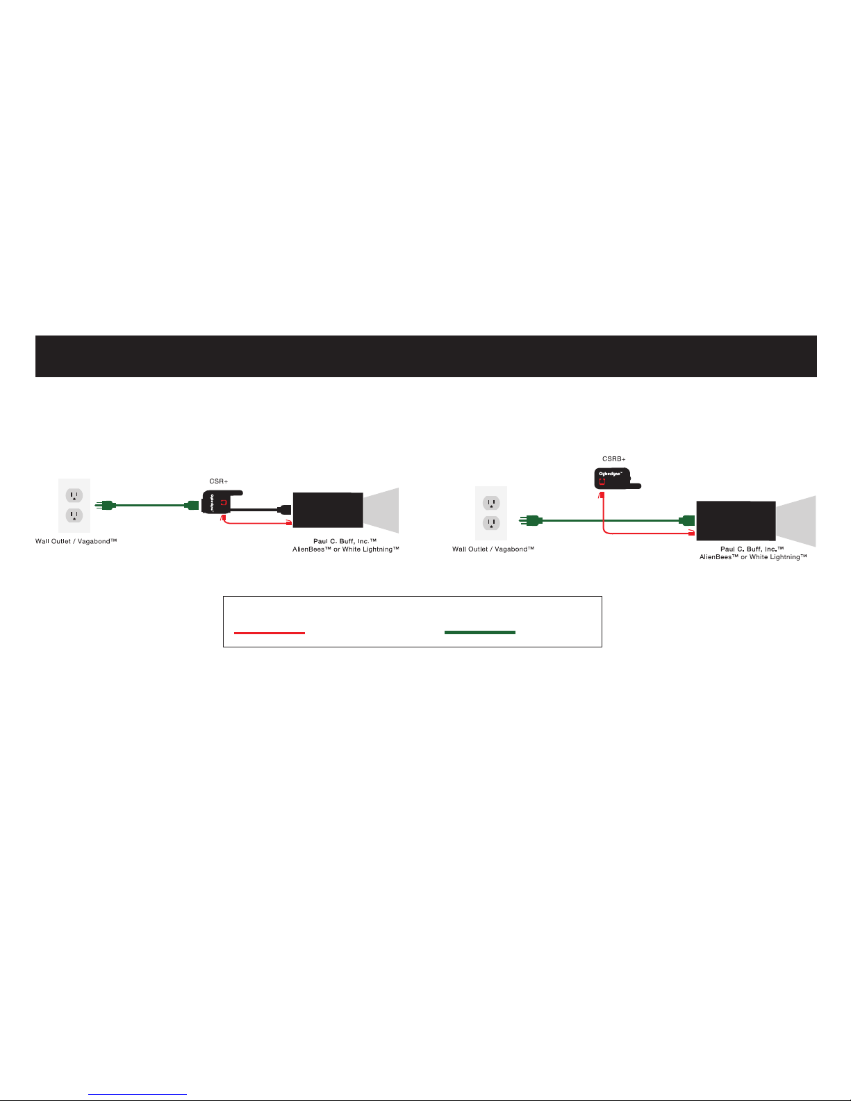
First, connect the CyberSyncTM Plus model receiver to the flash unit (as shown in above diagram). Next, set the sliders located on the
back panel of the flash unit to FULL POWER, making sure all modeling light buttons are pressed in. Then, set the FREQUENCY dial to
the same number that the transmitter is set to. Finally, set each receiver to it’s own individual channel (ONLY using channels 1 thru 4)
on the CHANNEL dial.
INITIAL SETUP TRANSMITTER and RECEIVER / TRANSCEIVER
LEGEND
RJ-11 Telephone-style Cord AC Power Cable
Page 4
4
INITIAL SETUP TRANSMITTER and RECEIVER / TRANSCEIVER
DigiBee / Einstein
TM
First, insert the transceiver into the transceiver receptacle located on the top of the DigiBeeTM or EinsteinTM. Next, turn on the flash unit(s).
For the DigiBee, press the FREQUENCY button located on the control panel on the back on the unit. Then, choose the frequency
that the transmitter is set to by using the up and down arrows on the back of the unit. Finally, set each flash unit to their own
individual channel (ONLY using channels 1 thru 4) by pressing the CHANNEL button and using the arrows to select the channel.
For the EinsteinTM, use the function button located on the back control panel and scroll through the fields on the LCD screen
until the channel (“CH”) field is highlighted blue. Use the arrows to select the channel (ONLY using channels 1 thru 4).
Press the function button again to highlight FREQ on the back control panel. Once highlighted, use the arrows to select the frequency.
NOTE: Make sure that all components are set to the SAME FREQUENCY but each flash unit is set to its own INDIVIDUAL CHANNEL
(ONLY using channels 1 thru 4).
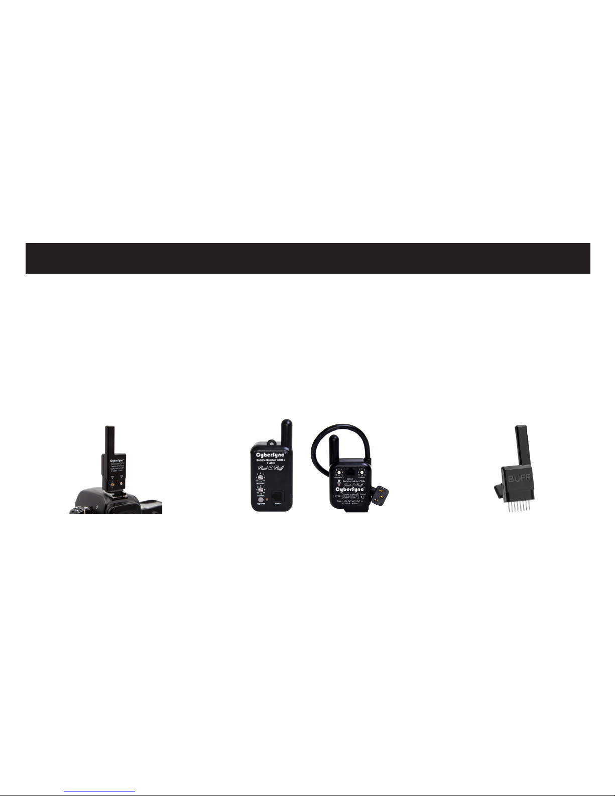
CyberSyncTM Plus Model Receivers
(CSR+ or CSRB+)
For use with: AlienBeesTM and White LightningTM
CyberSyncTM Trigger Transmitter 2 (CST2)
CyberSyncTM Tranceiver (CSXCV)
For use with: DigiBee and Einstein
TM
Page 5
*The sliders have no function when the CyberSense is in this mode.
INITIAL SETUP SETTING THE FREQUENCY
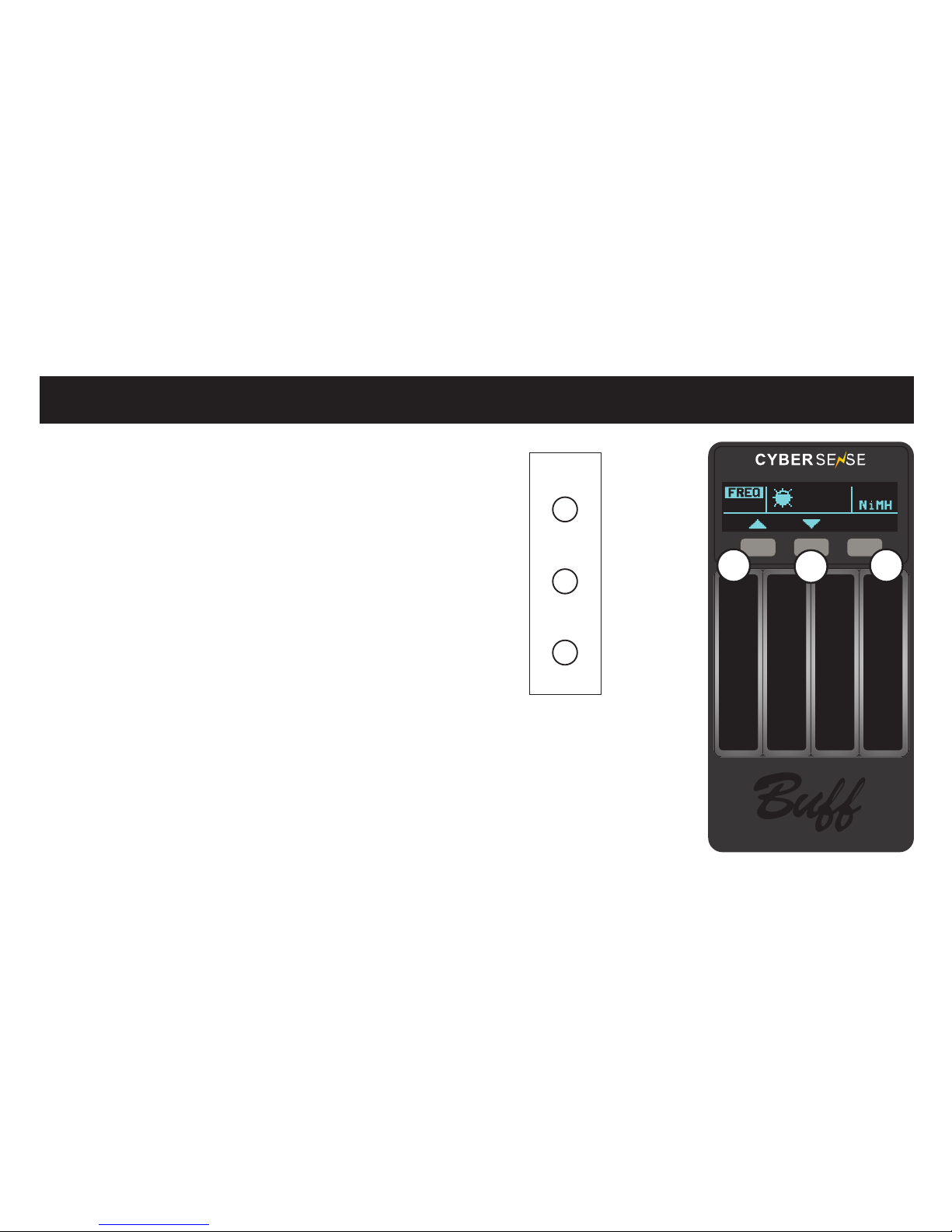
Turn on the CyberSense remote by pressing ANY button.
Press the (R) button to access the SETUP mode.
While in the SETUP mode, press the (L) button to enter
the FREQUENCY (FREQ) mode.
Match the FREQUENCY number that the transmitter
and transceiver / receiver are set to by using the
UP (L) or DOWN (C) buttons.
Once your FREQUENCY is set, press in on the
(R) button (DONE) to complete your FREQUENCY setup.
The CyberSense will then revert back
to the either the MODEL or FLASH ADJUST screen.
CH1 CH2 CH3 CH4
05
SLEEP
45
s
DONE
BATT
L
C
R
5
R
RIGHT
LEGEND
L
LEFT
C
CENTER
Page 6

The CyberSense is equipped to control up to four different flash units using
the touch sensitive sliders.
Each slider corresponds with the channel label (CH1, CH2, CH3, CH4)
that is located above the CyberSense digital display.
TOUCH AND HOLD the slider, for approx. 2 sec., that corresponds
to the channel that the flash unit receiver/transceiver is set.
Once the CyberSense establishes communication with the flash unit that
is attempting to be added, the current flash setting for that flash unit will
appear in the digital display associated with that channel.
*If the CyberSense cannot communicate with a flash unit on that channel,
the display dashes (---) will blink three times. If this happens, verify
the frequency and distance the CyberSense is from the flash unit.
Repeat the above steps until all flash units are added.
CONNECTING TO FLASH UNITS
CH1 CH2 CH3 CH4
SETUPTEST FLASH
6
Page 7
7
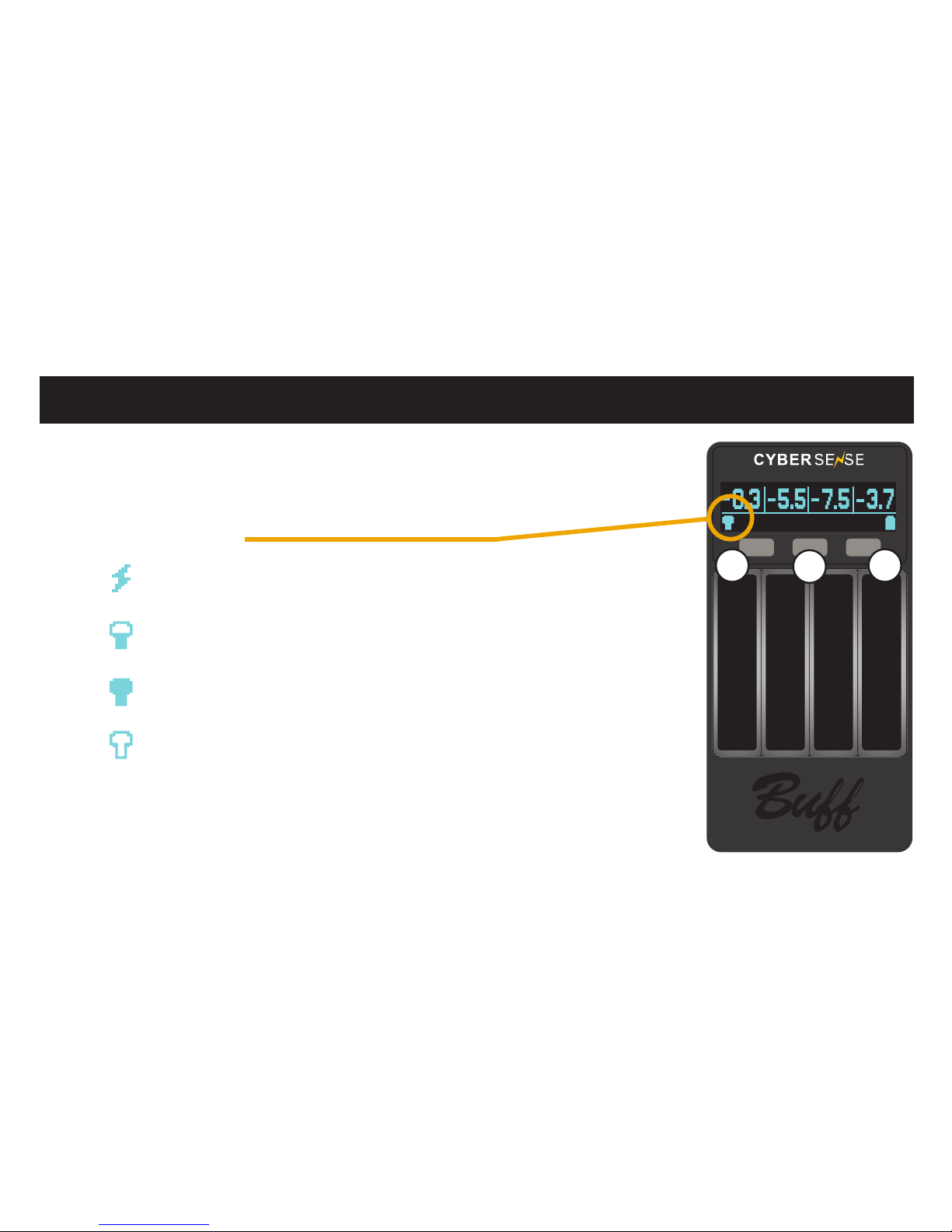
CHANGING THE MODELING MODE
CH1 CH2 CH3 CH4
SETUPFULL MODEL
L
C
R
MODELING MODE
Press the (C) button to access the MODEL mode.
MODEL will appear in the digital display above the (C) button.
Press the (L) button to toggle between the MODEL settings.
MODEL SETTINGS
TRACK Modeling lights will brighten or dim as the flash
output is adjusted up or down.
ADJ Modeling light output can be adjusted independently
from the flash output.
FULL Modeling light remains at full power, regardless
of flash output.
OFF Modeling light shuts off.
The model mode chosen affects ALL CHANNELS on the CyberSense.
Example: CH1 cannot be set to TRACK and CH2 cannot stay on FULL POWER.
NOTE: The (C) button functions as a toggle between the FLASH and MODEL modes.
Page 8
ADJUSTING FLASH OUTPUTS / STANDBY MODE
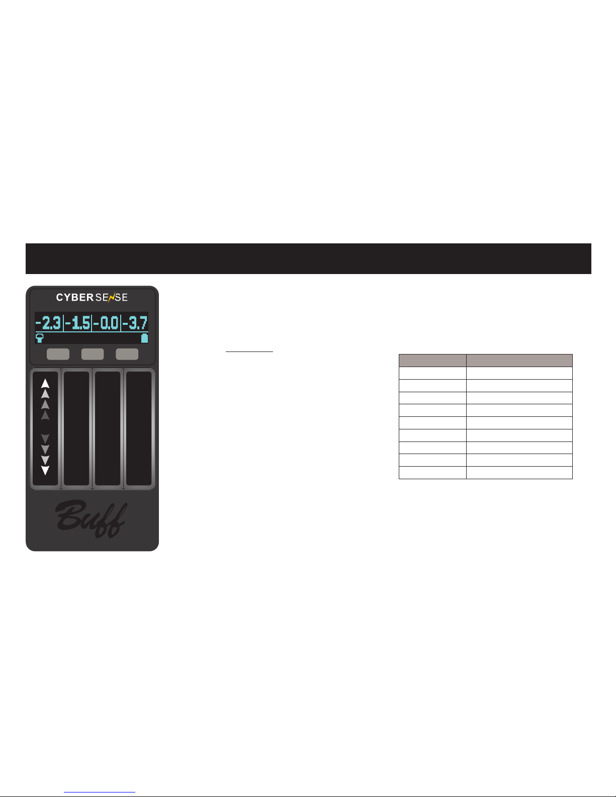
ADJUSTING FLASH OUTPUTS IN THE FLASH MODE
Using the TOUCH SLIDER associated with the channel that
the flash unit is set to, SLIDE UP to INCREASE the output,
and SLIDE DOWN to DECREASE the output.
EXAMPLE
EinsteinTM with 9 f-stop variability
flash output breakdown indication:
*Sliders adjust in 1/10 of a stop.
STANDBY MODE
To put a particular flash unit in STANDBY, simply DOUBLE-TAP the touch
slider for that particular channel. The digital display will show OFF under
the channel icon for that particular flash. To turn the flash unit back ON,
simply DOUBLE-TAP the touch slider.
F-STOP OUTPUT EQUIVALENT
FULL 0.0
1/2 -1.0
1/4 -2.0
1/8 -3.0
1/16 -4.0
1/32 -5.0
1/64 -6.0
1/128 -7.0
1/256 -8.0
8
CH1 CH2 CH3 CH4
SETUPTEST FLASH
OR
Page 9
ADJUSTING MODELING LIGHTS
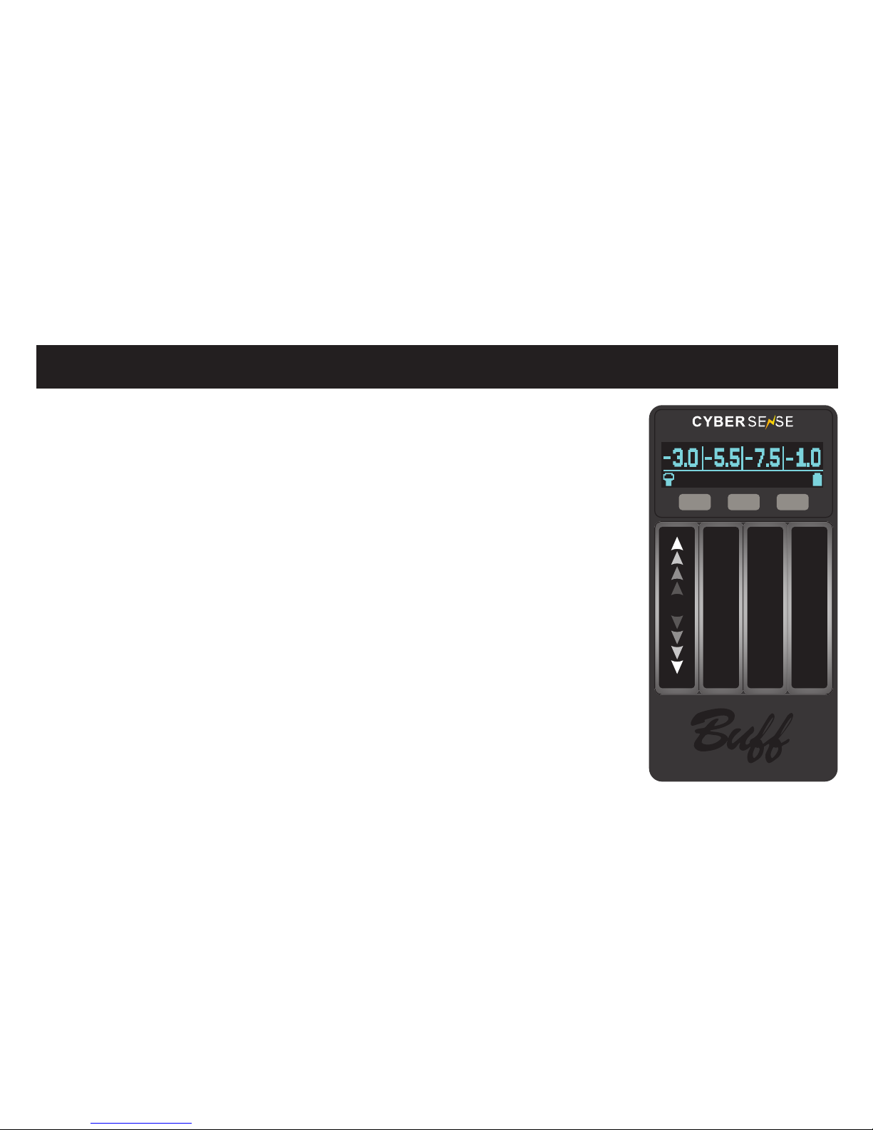
ADJUSTING MODELING LIGHTS IN THE MODEL MODE
When the MODELING MODE is set to ADJUST (ADJ), use the TOUCH SLIDER
associated with the channel the flash unit is set to; SLIDE UP to INCREASE
the output, and SLIDE DOWN to DECREASE the output.
The sliders for the modeling lights adjust in 1/10 of a stop.
To turn any individual modeling light OFF, simply DOUBLE-TAP the TOUCH
SLIDER for that specific channel. The digital display will show OFF under the
channel icon for that particular flash unit. To turn the modeling light back ON,
simply DOUBLE-TAP the TOUCH SLIDER.
CH1 CH2 CH3 CH4
SETUPADJ MODEL
9
OR
Page 10
ADJUSTING DISPLAY BRIGHTNESS AND SLEEP TIMER
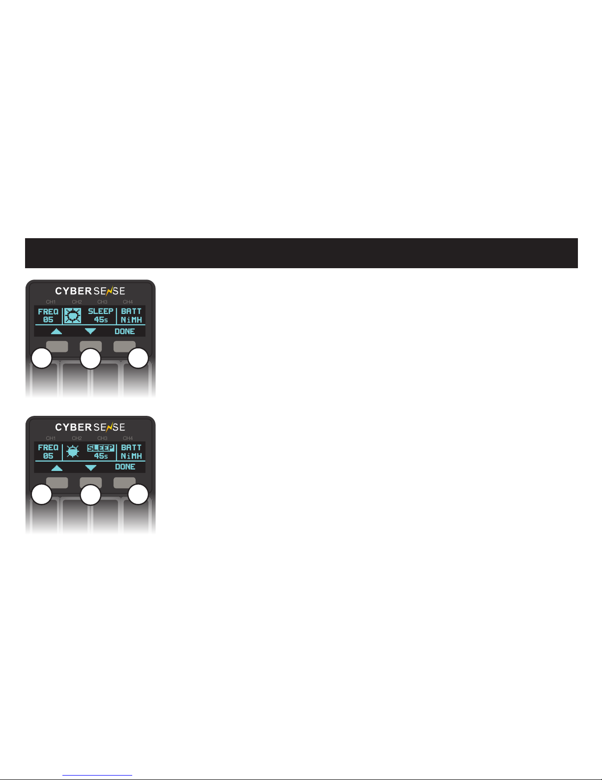
ACCESS THE SETUP MENU
Press the (R) button indicated by SETUP in the digital display.
Press the (C) button to enter DISPLAY SETUP (DISP).
*The sliders have no function when the CyberSense is in these modes.
DISPLAY BRIGHTNESS ADJUSTMENT
In DISPLAY SETUP mode, you can adjust the brightness of the digital
display by pressing the (L) button, indicated with BRIGHT, in the
digital display. Then, press the (L) or center (C) buttons to increase
or decrease the brightness of the display. Finally, press the (R) button,
indicated with DONE in the digital display, to finalize your changes.
CH1 CH2 CH3 CH4
05
SLEEP
45
s
BATT
FREQ
DONE
L
C
R
10
SLEEP TIMER ADJUSTMENT
In DISPLAY SETUP mode, you can adjust the SLEEP setting of the
digital display by pressing the (C) button, indicated with SLEEP in the
digital display. Then, press the (L) or (C) buttons to increase or decrease
the sleep setting timeout. The unit can be set to go into SLEEP mode
anywhere from 15 seconds to 15 minutes. Finally, press the (R) button,
indicated with DONE in the digital display, to finalize your changes.
To turn OFF the CyberSense before it enters SLEEP mode, press and
hold the (R) button until the unit shuts off.
CH1 CH2 CH3 CH4
05 45
s
DONE
BATT
FREQ
SLEEP
L
C
R
Page 11
ADJUSTING BATTERY TYPE
*The sliders have no function when the CyberSense is in these modes.
CH1 CH2 CH3 CH4
05 45
s
DONE
FREQ
SLEEP
ALK
BATT
L
C
R
11
BATTERY ADJUSTMET
NOTE: The CyberSense attemps to automatically detect whether the
installed batteries are alkaline or NiMH on start-up. This mode is only
necessary when the CyberSense’s automatic detection is incorrect.
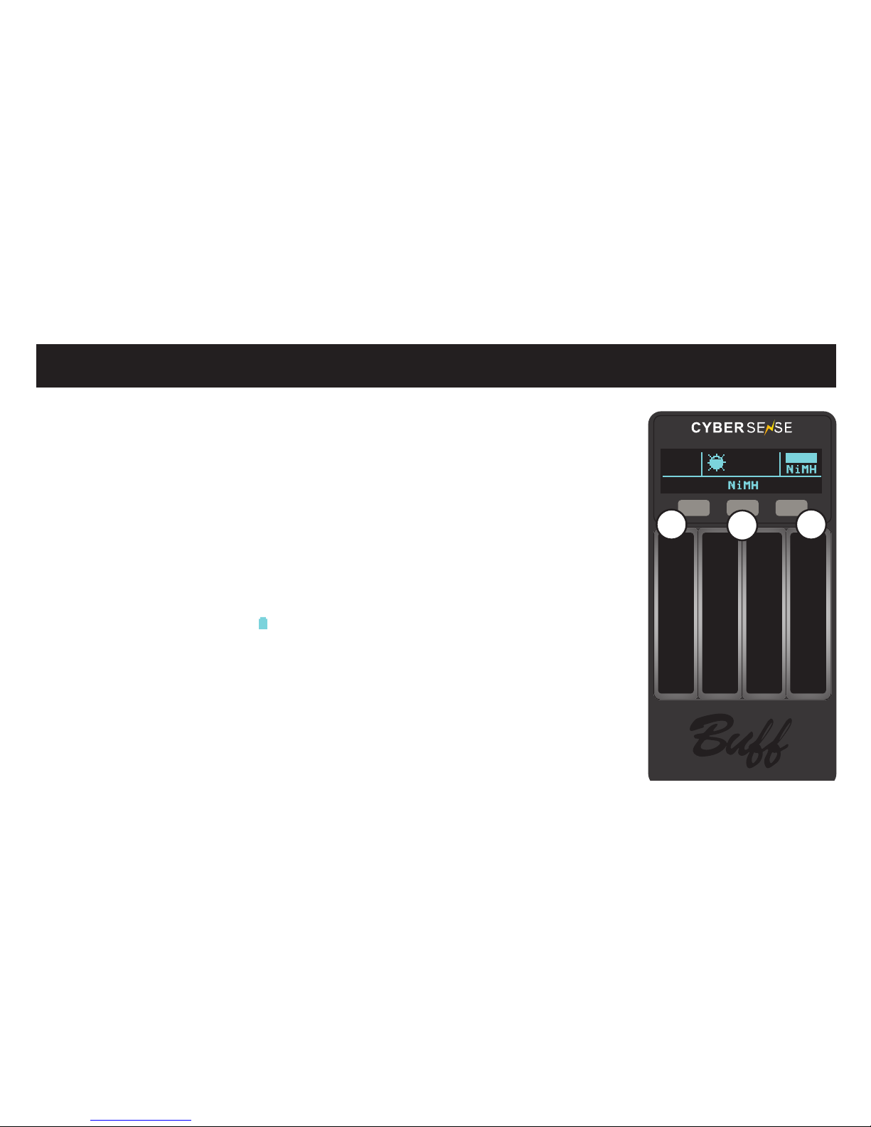
Press the (R) button indicated by SETUP in the digital display.
Press the (R) button to enter BATTERY (BATT) setup.
In BATTERY SETUP (BATT) mode, you can set which battery is being used
in the CyberSense. Options include: Alkaline (ALK), indicated above the
(L) button in the digital display, or Nickel Metal Hydride (NiMH), indicated
above the (C) button in the digital display. Finally, press the (R) button
indicated with DONE in the digital display to finalize your changes.
NOTE: The battery gauge ( ) will indicate the amount of energy left
in the battery. The icon will show the depletion of the battery in various
stages. The battery icon will flash when it is time to replace the batteries
in the CyberSense. If the battery life has been completely exhausted, it
will power on and prompt to replace the batteries before
you are able to proceed with using the remote.
Page 12

Paul C. Buff, Inc. guarantees all CyberSyncTM products for a period of two years from date of purchase.
We will, at our option, repair or replace any CyberSyncTM product that becomes defective during this period.
Batteries are excluded from this warranty, as is any damage resulting from improper use.
No claim is made for the suitability of this product for any intended use and no liability is implied
or assumed beyond the repair or replacement of this product.
Defective units should be returned to us at the address below with a note explaining the defect or problem.
We will return repaired or replaced units to you at our cost.
Designed in the USA by: Paul C. Buff, Inc., 2725 Bransford Ave., Nashville, TN 37204 USA
Toll Free: 1.800.443.5542 (USA) | Local: 615.383.3982 | [email protected] | paulcbuff.com
SAFETY AND LEGAL INFORMATION
- This product is NOT sealed or waterproof. - The only user-serviceable parts in this product are the batteries.
- When not in use, store in a dry environment where the temperature will not fall below -4° F (-20° C) nor exceed 158° F (70° C).
We recommend that you remove the batteries to prevent damage from corrosion during long-term storage.
FCC ID: OUECBRSNS
This device complies with Part 15 of the FCC Rules. Operation is subject to the following two conditions: (1) this device may not cause
harmful interference, (2) this device must accept any interference received, including interference that may cause undesired operation.
@PAULCBUFFINC
 Loading...