

Bueno Electric HFD8M-2SSC, HFD8M-W, HFD8M-2SSC-W, HFD8M-4SC-W, HFD8M-4SC Software Configuration Manual
...
Https://www.bueno-electric.com
BUENO ELECTRIC
BUENO ELECTRICBUENO ELECTRIC
BUENO ELECTRIC
Managed Ethernet Switch
User’s Manual

Information Coding: UM00D908
Version: V1.1
Product version: all
Product Name: Managed Industrial Ethernet Switches on DIN Rail and Rack.
Applicable to: Technical Support
Attention:
This document will be updated on regular bases due to version upgrades or
other requirements.
Unless otherwise agreed on, this document is only to be used as a guide and
not for warranty purposes.

Https://www.bueno-electric.com
BUENO ELECTRIC
BUENO ELECTRICBUENO ELECTRIC
BUENO ELECTRIC
Table of Contents
Chapter 1
Getting Started iv
1. S
ERIAL CONSOLE CONFIGURATION
..................................................................
IV
2. U
SER NAME AND PASSWORD
.............................................................................
V
3. C
ONSOLE MENU
................................................................................................
V
Chapter 2
Web Management Function vii
1. L
OGIN TO THE WEBSERVER
.............................................................................
VII
2. S
YSTEM STATUS
.............................................................................................
VIII
3. P
ORT SETTING
..................................................................................................
IX
3.1
Port Setting ............................................................................................... ix
3.2
Storm Protection ........................................................................................ x
3.3
Bandwidth Setting ...................................................................................... x
4. VLAN S
ETTING
................................................................................................
XI
4.1
Port VLAN ................................................................................................ xii
4.2
VLAN Table .............................................................................................. xii
5. QOS ................................................................................................................
XIV
5.1
QoS Setting.............................................................................................. xiv
5.2
DSCP QoS ................................................................................................ xv
6. L
INK MANAGEMENT
.......................................................................................
XVI
6.1
RSTP ....................................................................................................... xvi
7. N
ETWORK MANAGEMENT
............................................................................
XVIII
7.1
Port Trunking ........................................................................................ xviii
7.2
SNMP Setting .......................................................................................... xix
7.3
Port Mirror .............................................................................................. xx
7.4
IGMP Snooping ...................................................................................... xxi
7.5
GMRP .................................................................................................... xxii
8. N
ETWORK STATISTIC
....................................................................................
XXIII
8.1
Mac Address Table................................................................................ xxiii
8.2
Traffic Statistics .................................................................................... xxiii
9. S
YSTEM MANAGEMENT
................................................................................
XXIV
9.1
Device Address ...................................................................................... xxiv
9.2
User Management .................................................................................. xxv
9.3
Log Information .................................................................................... xxvi
9.4
File management ................................................................................. xxviii

Chapter 1 Getting Started
In this chapter we explain how to install a managed switch for the first time.
There are three ways to access the managed switch’s configuration settings:
serial console, Telnet console, or web console.
If you do not know the switch’s IP address, you can open the serial console by
connecting the switch to a PC’s COM port with a short serial cable. You can
open the Telnet or web console over an Ethernet LAN or over the Internet.
1. Serial Console Configuration
First, please make sure the managed switches are connected via a serial
cable through the PC’s serial ports.
Next, open Hyper Terminal from the computer: Start → programs →
Accessories → Communication → HyperTerminal.
Once you have opened Hyper Terminal, you need to create a new connection,
select the communication port to the switch, and set the parameter as follows:
115200 for Baud Rate, 8 for Data Bits, None for Parity, and 1 for Stop Bits.

Https://www.bueno-electric.com
BUENO ELECTRIC
BUENO ELECTRICBUENO ELECTRIC
BUENO ELECTRIC
2. User Name and Password
When HyperTerminal finish setting, you can see the page display as below :
Enter User Name and Password, the default User Name and Password as
“admin”, then press “Enter”, go into Console Program.
3. Console Menu

Console menu includes the following:
The default IP address for managed switches is 192.168.19.16. You can set
IP address as follows:
Switch>>ip address 192.168.0.1
When IP Address is set, you can access the Web page through this IP
address.

Https://www.bueno-electric.com
BUENO ELECTRIC
BUENO ELECTRICBUENO ELECTRIC
BUENO ELECTRIC
Chapter 2 Web Management Function
The switch’s web console is a convenient platform for modifying the
configuration and accessing the built-in monitoring and network administration
functions. You can open the switch’s web console using a standard web
browser, such as Internet Explorer.
1. Login to the Webserver
Please open a browser and enter in the address bar the switch IP address, for
example: http://192.168.19.16 once you have done so, please press “Enter”.
Once you have completed the above the following window will appear and you
are to type in your User Name and Password.
Please note that the default IP address is “admin”.
Input correct User Name and Password login to Webserver and we
recommend you to change User Name and Password.

2. System Status
Setting
Description
Time Zone Specifies the time zone, which is used to determine the
local time offset from GMT (Greenwich Mean Time).
Time Setting Use the local time or enables NTP time server functionality.
NTP Server Set NTP server IP address.
System Time Show the switch system time.
PC Time Show the PC time .

Https://www.bueno-electric.com
BUENO ELECTRIC
BUENO ELECTRICBUENO ELECTRIC
BUENO ELECTRIC
Update PC Time to Switch Click this button and the switch time will be set according
to the PC time.
Switch Name Give a different name for each switch.
Contact Info Display contact info for technical support.
Contact Address Describe the location of switches installed.
MAC Address Show the switch’s MAC address.
Hardware Version Show the hardware version.
Software Version Show the software version.
System Up Time Indicates how long the switch remained up since the last
start.
After finishing inputting info, click on “Save” to save info.
3. Port Setting
3.1 Port Setting

Setting
Description
Port Enable Allows data transmission through the port or not.
Port Speed Allows the port to use the IEEE 802.3u protocol to
negotiate with connected devices. The port and connected
devices will determine the best speed for that connection.
Choose one of these fixed speed options if the connected
Ethernet device has trouble auto-negotiating for line speed.
Duplex Mode Set Auto, Full or Half.
Traffic Limiting Enable or disable traffic control function.
Port Range You can select from the following port.
3.2 Storm Protection
Setting
Description
Storm Protection Enable / Disable protection function.
Broadcast Packets
Indicate the packet rate, the range 1-30Mbps.
Limited Type Broadcast packet, multi-cast packet or Unknown unicast
packet.
3.3 Bandwidth Setting

Https://www.bueno-electric.com
BUENO ELECTRIC
BUENO ELECTRICBUENO ELECTRIC
BUENO ELECTRIC
The switches provide Port Control Rate Limit, including Ingress and Egress
Rate Limit.
4. VLAN Setting
A Virtual, commonly known as a VLAN, is used to create independent logical
networks within a physical network. Several VLANs may co-exist within such a
network. VLAN can effectively reduce the scope of Broadcast, and it’s
convenient to manage network through logical network segment (for example,
company’s department) that cannot conduct data exchange and is separated.
As a matter of fact, if you add a router between different virtual network
segments, they can conduct data exchange through router.
Managed switches support IEEE802.1Q VLAN. There are three types of VLAN
port settings:
Access Port:
The port connects to a single device that is not tagged. The user must
define the default port PVID that assigns which VLAN the device belongs to.
Once the ingress packet of this Access Port egresses to another Trunk Port
(the port needs all packets to carry tag information), the switch will insert
this PVID into this packet so the next 802.1Q VLAN switch can recognize it.
Trunk Port:
The port connects to a LAN that consists of untagged devices, tagged
devices and/or switches and hubs. In general, the traffic of the Trunk Port

must have a Tag. Users can also assign a PVID to a Trunk Port. The
untagged packet on the Trunk Port will be assigned the port default PVID as
its VID.
Hybrid Port:
The port is similar to a Trunk port, except users can explicitly assign tags to
be removed from egress packets.
4.1 Port VLAN
Setting
Description
Port Range Select port to set.
Port Type Three types of VLAN port Access, Trunk or Hybrid can
be selected.
PVID Assigns the VLAN ID, the range is 1~4094.
Vlan-allowed The VLAN ID allowed to pass. Only valid if port type is
trunk.
Vlan-untaged Remove the tag for the port. Only valid if port type is
trunk.
4.2 VLAN Table

Https://www.bueno-electric.com
BUENO ELECTRIC
BUENO ELECTRICBUENO ELECTRIC
BUENO ELECTRIC

Setting
Description
VID VLAN ID
VLAN Name The name of VLAN
The table shows the VLAN groups that were created.
5. QoS
The switch’s traffic prioritization capability provides Quality of Service (QoS) to
your network by making data delivery more reliable. You can prioritize traffic
on your network to ensure that high priority data is transmitted with minimum
delay.
Traffic can be controlled by a set of rules to obtain the required Quality of
Service for your network. The rules define different types of traffic and specify
how each type should be treated as it passes through the switch. The switch
can inspect IEEE 802.1p/1Q layer 2 CoS tags and improves the performance
and determinism of industrial networks for mission critical applications.
5.1 QoS Setting
Setting
Description
QoS Setting Enable / Disable QoS function.
QoS Priority
Queue
The switches support two different queuing mechanisms:
• Weight Fair: This method services all the traffic queues, giving
priority to the higher priority queues. Under most circumstances,
the Weight Fair method gives high priority precedence over low
priority, but in the event that high priority traffic does not reach the
link capacity, lower priority traffic is not blocked.
• Strict: This method services high traffic queues first; low priority

Https://www.bueno-electric.com
BUENO ELECTRIC
BUENO ELECTRICBUENO ELECTRIC
BUENO ELECTRIC
queues are delayed until no more high priority data needs to be
sent. The Strict method always gives precedence to high priority
over low priority.
The switch has 4 priority queues.
In the weight fair scheme, an 8, 4, 2, 1 weighting is applied to the
four priorities. This approach prevents the lower priority frames
from being starved of opportunity for transmission with only a slight
delay to the higher priority frames.
In the Strict-priority scheme, all top-priority frames egress a port
until that priority’s queue is empty, and then the next lower priority
queue’s frames egress. This approach can cause the lower
priorities to be starved of opportunity for transmitting any frames
but ensures that all high priority frames will egress the switch as
soon as possible.
802.1p QoS
Setting
Enable / Disable 802.1p QoS function.
802.1p Tag
Range
About IEEE802.1p priority, there are 8 classified levels available. In
IEEE802.1Q tags, there are 3 user priority levels. The switches
parameters default settings are listed below:
Tag Value
Default
Tag Value
Default
0 Low 4 Middle
1 Low 5 Middle
2 Normal
6 High
3 Normal
7 High
Priority
5.2 DSCP QoS

Setting
Description
DSCP QoS Setting Enable / Disable DSCP QoS function
DSCP Range
Maps different TOS values to 4 different egress queues. The
default setting is :
1 to 16: Low
17 to 32: Normal
33 to 48: Medium
49 to 64: High
DSCP Priority
6. Link Management
6.1 RSTP
Spanning Tree Protocol (STP) was designed to help reduce link failures on a
network, and provide an automatic means of avoiding loops. This is
particularly important for networks that have a complicated architecture, since
unintended loops in the network can cause broadcast storms. The switches’
STP feature is disabled by default. To be completely effective, you must
enable RSTP/STP on every the switch connected to your network.
Rapid Spanning Tree Protocol (RSTP) implements the Spanning Tree
Algorithm and Protocol defined by IEEE 802.1D-2004. RSTP provides the
following benefits:

Https://www.bueno-electric.com
BUENO ELECTRIC
BUENO ELECTRICBUENO ELECTRIC
BUENO ELECTRIC
The topology of a bridged network will be determined much
more quickly compared to STP.
RSTP is backward compatible with STP, making it relatively
easy to deploy.
Setting
Description
RSTP Setting Enable / Disable RSTP function.
Bridge Priority Increase this device’s bridge priority by selecting a lower number.
A device with a higher bridge priority has a greater chance of
being established as the root of the Spanning Tree topology.
Hello Time The root of the Spanning Tree topology periodically sends out a
“hello” message to other devices on the network to check if the
topology is healthy. The “hello time” is the amount of time the
root waits between sending hello messages.
Max Age Time
If this device is not the root, and it has not received a hello
message from the root in an amount of time equal to “Max. Age,”
then this device will reconfigure itself as a root. Once two or more
devices on the network are recognized as a root, the devices will
renegotiate to set up a new Spanning Tree topology.
Forwarding Delay
The amount of time this device waits before checking to see if it
should change to a different state. The value range is 4~30s.
Bridge Information Show the current bridge information.

Port Cost
Input a higher cost to indicate that this port is less suitable as a
node for the Multiple Spanning Tree topology. Use the default
value (0) to use port speed in the auto port cost.
Priority
Increase this port’s priority as a node on the Multiple Spanning
Tree topology by entering a lower number.
Point to Point Port If the port is connected to only one bridge, the port is called point
to point port.
Edge Port Select to enable or disable the port as the edge port.
In RSTP info page, the RSTP information can be shown:
7. Network Management
7.1 Port Trunking
Trunking, sometimes called Link Aggregation, is a way to parallel Switch ports
using a few cables to improve the bandwidth and generate link redundancy.
Trunks are a very useful function in building redundancy network. Managed
series of switches provide Trunking function, which allows two or more ports to
be a group of Trunking as a single logical link in order to improve the
bandwidth and link redundancy; when a physical connection cannot
communicate or fails, other link in Trunking group will take over and maintain
communications, in this case fast recovery mechanism is set up.
Https://www.bueno-electric.com
BUENO ELECTRIC
BUENO ELECTRICBUENO ELECTRIC
BUENO ELECTRIC
Setting
Description
Trunk Index Totally 2 groups.
Port Members Lists the ports in the current trunk group and the
ports that are available to be added.
Enable Enable / Disable the function.
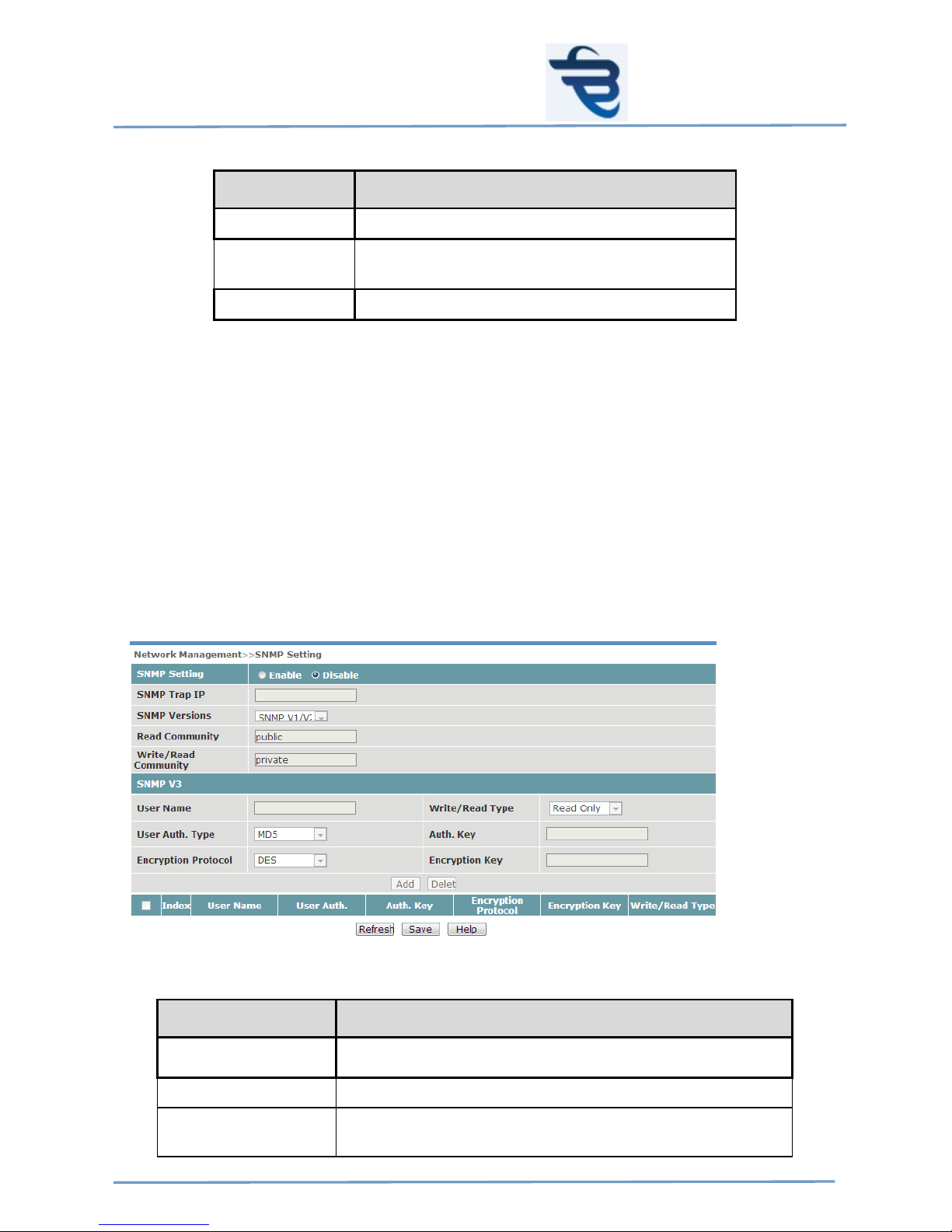
7.2 SNMP Setting
The switch supports SNMP V1, V2c, and V3. SNMP V1 and SNMP V2c use a
community string match for authentication, which means that SNMP servers
access all objects with read-only or read/write permissions using the
community strings public and private by default. SNMP V3 requires that you
select an authentication level of MD5 or SHA, and is the most secure protocol.
You can also enable data encryption to enhance data security.
SNMP V1/2 Setting is shown in the following table:
Setting
Description
SNMP Trap IP Specifies the IP address or name of the primary trap server
used by your network.
SNMP Version SNMP version.
Read Community Specifies the community string to authenticate the SNMP
agent for read-only access. The SNMP agent will access

all objects with read-only permissions using this community
string.
Write/Read
Community
Specifies the community string to authenticate the SNMP
agent for read/write access. The SNMP server will access
all objects with read/write permissions using this
community string.
SNMP V3 Setting is shown in the following table:
Setting
Description
User Name User Name.
Write/Read Type The write/read type selection.
User Auth. Type Provides authentication based on HMAC-MD5, or HMAC-SHA
algorithms. 8-character passwords are the minimum requirement
for authentication.
Auth. Key The Encryption key.
Encryption Protocol The encryption protocol could be DES, AES or 3DES.
Encryption Key Encryption Key.
7.3 Port Mirror
The Mirror Port function can be used to monitor data being transmitted
through a specific port. This is done by setting up another port (the mirror port)
to receive the same data being transmitted from, or both to and from, the port
under observation. Using a mirror port allows the network administrator to sniff
the observed port to keep tabs on network activity.
Setting
Description

Https://www.bueno-electric.com
BUENO ELECTRIC
BUENO ELECTRICBUENO ELECTRIC
BUENO ELECTRIC
Port Mirror Enable / Disable the function.
Mirror Port Select the number of the port that will be
used to monitor the activity of the monitored
port.
Monitored Port Select the number of the ports whose
network activity will be monitored.
Watch Direction Select one of the following two watch
direction options:
Input data stream:
Select this option to monitor only those data
packets coming into the switch’s port.
Output data stream:
Select this option to monitor only those data
packets being sent out through the switch’s
port.
Bi-directional:
Select this option to monitor data packets
both coming into, and being sent out
through, the switch’s port.
7.4 IGMP Snooping
IGMP Snooping provides the ability to prune multicast traffic so that it travels
only to those end destinations that require that traffic, thereby reducing the
amount of traffic on the Ethernet LAN.

Setting
Description
IGMP snooping Setting Enable / Disable the function.
IGMP Querier Enable / Disable IGMP Querirer function.
Query Interval Sets the query interval of the Querier function
globally. Valid settings are from 20 to 600
seconds.
Multicast Age Time The age time of the broadcast member.
Static Multicast MAC Static Multicast MAC
VLAN ID The ID of static multicast MAC
Port Range The port range of static multicast MAC
7.5 GMRP
The switches support IEEE 802.1D-1998 GMRP (GARP Multicast Registration
Protocol), which is different from IGMP (Internet Group Management Protocol).
GMRP is a MAC-based multicast management protocol, whereas IGMP is IPbased. GMRP provides a mechanism that allows bridges and end stations to
register or de-register Group membership information dynamically. GMRP
functions similarly to GVRP, except that GMRP registers multicast addresses
on ports. When a port receives a GMRP-join message, it will register the
multicast address to its database if the multicast address is not registered, and
all the multicast packets with that multicast address are able to be forwarded
from this port. When a port receives a GMRP-leave message, it will deregister the multicast address from its database, and all the multicast packets
with this multicast address will not be able to be forwarded from this port.
Setting
Description
GMRP Setting Enable / Disable the function.
Multicast Address This multicast address is learned by GMRP.
VLAN ID VLAN ID is learned by GMRP.
Type The type of learned by GMRP.

Https://www.bueno-electric.com
BUENO ELECTRIC
BUENO ELECTRICBUENO ELECTRIC
BUENO ELECTRIC
8. Network Statistic
8.1 Mac Address Table
MAC Address and related forwarding port will display in this table.
Setting
Description
By Port No. Query by port no.
By MAC Address Type Query by MAC address type
8.2 Traffic Statistics
Managed series of switches conduct each port monitoring, and send all
network data packets and display them in Web page. The statics start
Statistics Package as soon as switches power on, when switch soft reset and
power down and reset, the data will zero.
When opening the page as below, the page will be refreshed ever 30
seconds .Please refer to the page below for detailed data display:

9. System Management
9.1 Device Address
This function will assign a managed IP Address for the switches. There are
two options that can be used to set Ethernet managed switch: automatic
assign (DHCP) and Fixed (Static) IP Address. Managed series of switches
default fixed IP address when they leave the factor. Automatically assign
(DHCP): Switches automatically obtain IP Address, Sub-net Mask, Gateway
and DNS Address from DHCP Server in network.

Https://www.bueno-electric.com
BUENO ELECTRIC
BUENO ELECTRICBUENO ELECTRIC
BUENO ELECTRIC
Setting
Description
DHCP/Fixed IP
Obtain an IP address automatically or assign a
fixed IP
IP Address Only IP Address is network
Subnet Mask Space range sub-net logical address use
Default Gateway Network Node, reach a entry port of network
DNS
Domain Name System, IP Address for Domain
Server
9.2 User Management
Setting
Description
User Index Represent a group of users.
Account Level The switch provides two levels of configuration access.
The admin account has read/write access of all
configuration parameters, and the user account has read
access only. A user account can view the configuration,
but will not be able to make modifications.
User Name User Name
Password User Password
Confirm Password Confirm the password

9.3 Log Information
Managed series of switches provide Log function, which can be easily enable
and disable.
When enabling the function, if the following event occurs, it will be recorded in
event list of switches.
System Reboot
Port Link Down / Link UP
Power Status Change
Login Information
Broadcast Storm Occurs
System Action and Operation Record
RSTP Net Status Change
NTP Time Synchronization

Https://www.bueno-electric.com
BUENO ELECTRIC
BUENO ELECTRICBUENO ELECTRIC
BUENO ELECTRIC
Setting
Description
Remote Syslog Setting Enable / Disable remote syslog.
Log Server Address Enter the IP address of Syslog server
Record Min Level The different level of log can be choose.
The log can be downloaded or be cleared by the user.

9.4 File management
Setting
Description
Configuration File
Backup
Configuration file for managed series of switches can be
saved in one PC, click “Export”, a saving dialogue box
prompts, select a proper file and save setting
parameters in PC.
Configuration File
Restore
Restore configuration file from PC , click
“Browse”
,
open a setting file, then click “Import”. After finish
recovering, switches need to reboot.
Firmware Upgrade Upgrade switch following the steps below:
Click “Browse”, open Firmware File(*.bin).
Click “Upgrade”, message box will prompts, if
clicking “OK” in it, start to upgrade, if clicking
“Cancel”, Quit upgrading. Firmware upgrading will
last for a period of time till switches restart.
Reset to factory
default
Restore factory default can restore factory default
quickly. Click “Start” in Web page, select “OK” in
confirmation information box prompted, and factory
default can be restored. After finishing restoring,
switches need to reboot.
System Restart
Click
“St
art” to restart the switch.

Https://www.bueno-electric.com
BUENO ELECTRIC
BUENO ELECTRICBUENO ELECTRIC
BUENO ELECTRIC
 Loading...