


ISO 9001 Registered Company
ISOMET 2000 Precision Saw
MA112480-20 03/06/00

Declaration of Conformity
Manufacturer: BUEHLER, Ltd.
Of: 41 Waukegan Road
Lake Bluff, Illinois 60044
Declares the following product: ISOMET 2000
To be in accordance with EC Directive(s);
Safety of Machinery: EMC Directive:
89/392/EEC and 91/368/EEC and 93/44/EEC
according to the following standards:
EN 292 PART 1 1991
EN 292 PART 2 1991
EN 60204 PART 1 1993
Position: Engineering Manager
Name: Chuck Motley
Signature:
Chuck Motley
89/336/EEC and 92/231/EEC according to the
following standards:
EN 50081-1: 1992
EN 50082-1: 1992
Date:
11/28/95
This Manual is a custom generated document. It includes all revisions
relative to this specific Buehler item as of the date shown below.
MA112480-20 03/06/00

Table of Contents
Warranty ...................................................................................................................................... 2
Unpacking.................................................................................................................................... 2
Assembly ..................................................................................................................................... 2
Installation.................................................................................................................................... 2
Location .......................................................................................................................... 3
Electrical ......................................................................................................................... 3
Blade Installation ............................................................................................................3
Cooling and Lubrication..................................................................................................4
Operation ..................................................................................................................................... 5
Energizing the Unit .........................................................................................................5
Specimen Loading..........................................................................................................5
Positioning the Sample...................................................................................................6
Setting the Load.............................................................................................................. 7
Checking and Adjusting Load......................................................................................... 8
Cutting the Specimen ..................................................................................................... 8
Blade Dressing ...............................................................................................................10
Pre-Dressing...................................................................................................................10
Dressing During the Cycle..............................................................................................10
Maintenance ................................................................................................................................ 11
General Specification: .................................................................................................... 11
Internal Coolant/Lubricant Recirculating System ........................................................... 11
Cleaning the Unit ............................................................................................................ 11
ISOMET™ 2000 Precision Saw Application Guide........................................................33
OPERATION AND MAINTENANCE INSTRUCTIONS
BUEHLER
ISOMET 2000 PRECISION SAW
MA112480-20 03/06/00
1

Warranty
Unpacking
Assembly
Figure 1 ISOMET™ 2000 Precision Saw
This unit is guaranteed against defective material and workmanship for
a period of two (2) years from date of receipt by customer. Warranty is
void if inspection shows evidence of abuse, misuse or unauthorized
repair. Warranty covers only replacement of defective materials.
If for any reason, this unit must be returned to our plant for warranty
service, please apply for prior authorization with shipping instructions,
and include the following information: Customer Purchase Order
Number, Buehler Invoice Number, Date, Serial Number, and reason for
return.
Carefully unpack and check contents. If any components are missing
or damaged, save the packing list and material and advise the carrier
and BUEHLER of the discrepancy.
The ISOMET™ 2000 Precision Saw is shipped fully assembled. A
Dressing Stick, three Specimen Chucks, two Flanges, one Diamond
Wafering Blade, one bottle of ISOCUT
and an accessory wrench are included. (Accessories available for use
with this unit.)
Installation
MA112480-20 03/06/00
2
®
Plus Cutting Fluid Concentrate,

Location
The ISOMET™ 2000 Precision Saw is intended for bench-top
placement. Select a location with convenient access to electrical and
water services.
Electrical
All units operate with a universal requirement range from 85-264V
50/60 Hz AC Input. Appropriate cord for country of use is supplied.
Blade Installation
Flanges support the Wafering and Abrasive Blades. Failure to provide
adequate flange support may result in curved cuts and damaged
blades. Always select the maximum flange diameter commensurate
with the size of the specimen to be cut. (See Accessories and
Supplies.)
1. Remove Thumb Screw and End Cap Bushing from Drive Shaft.
2. Install the Inner Flange on the Drive Shaft.
3. Install the blade against the inner Flange.
4. Slip on the Outer Flange and End Cap Bushing, then hand
tighten Thumb Screw to complete installation.
NOTE Before installation of a Wafering or Abrasive Blade, the End Cap
Bushing, Screw and Flanges should be cleaned in a mild detergent
solution to remove adherent particles from prior cutting. This will
prevent misalignment and damage to the Blade.
Figure 2 Blade Installation
Blade Dressing
New wafering blades, including the original equipment blade, must be
dressed before making sample cuts. Dressing removes the normal
smeared matrix metal and exposes the abrasive grain to assure free
cutting. New wafering blades should be dressed several times and
MA112480-20 03/06/00
3

older blades dressed as required based on the properties of the
sample material being cut. (See Maintenance: Blade Dressing.)
Cooling and Lubrication
Two different methods of applying coolant/lubricant are provided with
the ISOMET™ 2000 Saw. For most applications the self contained
recirculating system will provide adequate coolant flow. For optimum
cooling at extremely high cutting speeds with hard materials, the
ISOMET™ 2000 Saw can be connected to an external water supply
and drain. A water overflow protects the cutter in the event that the
drain becomes clogged or inadvertently closed. (See Accessories)
NOTE The unit's motor and recirculating system operate only when the cover
is closed. These machines have a water spray deflector built into the
hood, but if the cooling discharge water valve is opened too far, the
directional nozzles may force water between the hood and the top of
the cabinet. This water may well over the lip of the cabinet and run
down the sides of the machine.
Internal Coolant/Lubricant Recirculating System
When using the internal coolant system, fill the coolant tank with the
correct mixture of ISOCUT
®
PLUS Cutting Fluid Concentrate and
water. The fluid level should be approximately 5.0 cm (2″) deep or 4
liters.
ISOCUT
®
PLUS Cutting Fluid has been formulated for optimum cooling
and lubrication in medium and high speed cutting applications. It is a
water soluble concentrate which enhances the cooling properties of
water with effective lubrication and anti-corrosive properties.
ISOCUT
®
PLUS Cutting Fluid promotes clean cutting with diamond
blades or abrasive wheels for faster, superior quality cuts. A flow
control valve is provided at the base of the coolant tubes to prevent
excessive coolant from over-flowing at the hood, etc. (See Accessories
and Supplies for part numbers.)
Internal Pump
The Plumbing Assembly contained in this unit is only used with the
internal coolant/lubricant system. (See Figure 3). When external
coolant is used, the plumbing will be modified. Instructions are supplied
with the Accessory kit.
Check and change the cutting fluid as required.
NOTE When using abrasive cut-off wheels with the ISOMET™ 2000 Saw, the
coolant tank should be cleaned frequently, not exceeding the life of 3
wheels. (See Maintenance Section.)
MA112480-20 03/06/00
4

Figure 3 Internal Lubrication System
Operation
Energizing the Unit
1. Attach the blade and flanges as described in blade installation
section. Refer to Application Guide for proper blade selection.
2. Plug the unit into an appropriate power source.
NOTE Some types of GFI protection circuitry on the market are very sensitive
and may trip prematurely during machine start-up. If this happens, the
BUEHLER Service Department should be contacted to recommend a
solution.
3. Check the circuit breaker on the rear of the unit. It should be in
the (I) On position. Press the POWER ON Button. The green
LED control light should energize as well as all the LED
displays. The unit is now ready for specimen loading.
Specimen Loading
Several chucks are available to hold specimens of many different sizes
and shapes. (See Accessories and Supplies.) Select the proper chuck
for the particular application and attach to the support arm.
1. Open the hood and press the RAISE Button in the Arm section
2. Attach the Chuck to the Support Arm with the Thumb Screw.
3. Clamp specimen into the Chuck.
MA112480-20 03/06/00
on the Control Panel. See Figure 5. Raise the Support Arm all
the way up.
See Figure 4.
5

CAUTION Make sure the specimen is secured into chuck and the chuck to
the arm so that the specimen will not slip or rotate during cutting.
Improper clamping or chuck selection may cause blade damage.
Positioning the Sample
To position the specimen for cutting, the Position section of the Control
Panel in Figure 5 is used.
1. Press the RETRACT Button on the control panel until the
Support Arm and sample are clear of the Blade.
NOTE If the sample will not clear the blade, temporarily replace
the sample with a dummy of similar cross-section that can
clear the blade until after step 3 in this section.
2. Press LOWER Button on the control panel until the Support Arm
and sample are in the position shown in Figure 6A. If the
movement of the sample stops prior to reaching the position
shown, loosen the screw at the rear of the support arm and
adjust the arm as shown. Check to be sure there is enough
clearance so specimen can travel .25 (6 mm) past completion of
the cut to allow for overtravel during the automatic stop cycle.
NO EXTERNAL
FORCES APPLIED
3. Raise the Support Arm to a level approximately 1 cm above the
CAUTION Do not allow the Specimen to contact the Blade while adjusting
the position of the arm. Blade damage may result. Also do not
apply any external force (pushing with fingers) to arm. This will
cause damage to the electronics.
4. Press the ADVANCE Button on the Control Panel moving the
5. Adjust the Position until the desired cut specimen thickness is
MA112480-20 03/06/00
Figure 6A Support Arm Adjustment
blade.
Support Arm until the Specimen is even with the outer surface
of the blade. Press the ZERO DISPLAY Button on the Control
Panel, Figure 3. The MILLIMETER LED Display should now
read zero.
measured on the MILLIMETER LED Display. The position has a
25.4mm range and is graduated in 0.005mm increments.
6

NOTE The Support Arm can be raised/lowered and advanced/retracted with
the cover open or closed.
Figure 4 Specimen Chuck Adjustment
Setting the Load
To set the amount of force to be applied to the sample during the
cutting cycle, the Load section of the Control Panel is used. Refer to
Application Guide for proper load selection.
1. Preset the amount of load to be applied to the blade during the
cutting cycle. This is accomplished by pressing the LOAD
INCREASE or DECREASE Button until the desired load is
indicated on the Load LED Display.
NOTE The Display automatically sets to 100g when the unit is powered up.
The Load can be preset between 100g and 1000g in 10g increments.
NOTE The specimen must be loaded while the arm is in the raised position.
The ISOMET™ 2000 automatically tares the sample weight before a
cycle begins. The taring is done when the arm is in the raised position.
This features allows the saw to accurately apply the force displayed on
the front panel.
MA112480-20 03/06/00
7

Figure 5 Front Panel
Checking and Adjusting Load
During the cutting cycle, the ISOMET™ 2000 Saw will monitor the load
being applied to the blade. If an overload condition occurs, the system
will automatically decrease the load to maintain optimum cutting
conditions. A Bar Graph on the Control Panel indicates the % of set
load at which the unit is operating. Optimum cutting is attained when
the bar graph reads near or at 100% during the cycle.
To change the set load during operation, press the LOAD DECREASE
or INCREASE Button.
Cutting the Specimen
To cut the Specimen, the Load, Speed, Lubricant and Cycle portions on
the Control Panel are used.
1. Press the Lower Button on the Arm Section of the Panel until
the Specimen is approximately 1 cm above the Blade.
2. Close the cover.
WARNING The ISOMET™ 2000 Saw is designed to operate only with the cover
closed. This prevents manual feeding of sample materials or
dressing sticks into the rotating blade, which could result in
personal injury and/or blade damage. Efforts to defeat safety
interlock could result in personal injury.
3. Set the Blade speed by pressing the SPEED INCREASE or
4. Press the LUBRICANT ON Button if the cooling/lubricant system is
MA112480-20 03/06/00
DECREASE Buttons until the desired RPM is indicated on the
Speed LED Display. The speed can be set between 200 and 5000
RPM in 100 RPM increments. Refer to Application Guide on Page
29 for proper speed selection.
being used.
8

5. Press the CYCLE RUN Button. The Support Arm will begin to lower
and the Blade will rotate at the selected speed. The preset load will
not be applied for approximately 7 seconds. During this interval, the
sample will approach the blade and a 100g load will be applied in
order to establish a "kerf" cut. The unit will then apply the set load.
The ISOMET™ 2000 Saw is supplied with a 6″ dia. Wafering Blade
as standard equipment and the Support Arm is set at the factory to
accommodate this condition. In normal operation, the Arm automatically advances the specimen into the Wafering Blade until the
cut is completed or until the lower position limit switch within the
cutter is activated, whichever comes first. If the specimen does not
contact the Wafering Blade within seven seconds, the Arm will
automatically return to the start position without cutting the sample.
This could occur if a much smaller Wafering Blade is used or if the
sample is very small and the Specimen Arm is not repositioned.
Figure 6 shows the factory set Arm position (when the arm is
raised to it’s maximum) relative to the various size Wafering
Blades that may be used with the ISOMET™ 2000 Saw. It is
easy to see that there is a considerable distance for the Support
Arm to travel before making contact with a four inch diameter
blade. The support arm should be lowered with the LOWER
button until the specimen is about 1 cm. from the blade before
starting the cut cycle.
If necessary to allow for a variety of operational conditions, the
Support Arm may be repositioned. This is accomplished by
loosening the Mounting Screw that secures the Support Arm to
the shaft. Be careful to prevent the Support Arm from striking
the Wafering Blade. Reposition the Support Arm as described in
Positioning The Sample section on page 6.
NOTE Do not move the specimen arm laterally along the shaft. The arm has
25.4 cm of stroke. Any loss in stroke by repositioning the arm may
result in the arm stalling against the cabinet resulting in loss of
micrometer accuracy.
Figure 6 Support Arm Adjustment
6. During operation, observe the Load Bar Graph. Due to
differences in sample thickness and density/consistency, or as
MA112480-20 03/06/00
9

the blade surface "loads up" when cutting soft materials, the %
set load may vary as the system adjusts for optimum load
conditions. (See Checking and Adjusting Load.)
NOTE If the bar graph does attain 100%, the removal rate may be too high for
the material being cut. (Example: thin wall tubing. The arm may retract
as if "end of cut". To correct for this type of material, the load or speed
should be reduced.
When the Support Arm reaches the end of the cut, it will return to its
upright position and the blade will stop.
NOTE If, at any time during the cutting mode, the operator lifts the cover or
presses the CYCLE STOP Button, the Support Arm will return to its
upright position and the blade will stop immediately.
7. At the end of operation, press the POWER OFF Button.
The ISOMET™ 2000 Saw will retain the last set of parameters
that were used even when the Power Off Button is pressed or if
the unit is disconnected from the power source.
Blade Dressing
Position the Dressing Stick in the Dressing Chuck shown in Figure 7.
Dressing should always be performed with coolant/lubricant.
WARNING The ISOMET™ 2000 Saw is designed to operate only with the
hood closed. Overriding this safety feature could result in serious
injury or equipment damage.
Pre-Dressing
To Pre-Dress the blade, close the hood and press the dressing
CHUCK RETRACT Button on the Control Panel. Hold this button until
the dressing chuck body retracts clear of the blade. Insert the dressing
stone in the clamp placing the edge of the stone approximately 1/16″
behind the blade. Secure the stone by tightening the thumbscrew.
Close the hood. Press the LUBRICANT ON Button to activate the
coolant. Press and hold the DRESSING CHUCK ADVANCE Button
until the stone begins to advance. As the stone advances toward the
blade the saw blade will automatically turn at 500 rpm for optimum
dressing. Continue advancing the stone until it touches the blade. Now
push the button intermittently advancing the stone slowly into the
blade. Press the DRESSING CHUCK RETRACT Button to return the
chuck back to the starting Pre-Dress position. Repeat as required.
NOTE To terminate the dressing cycle at any time simply stop pressing the
DRESSING CHUCK ADVANCE/RETRACT Buttons for a minimum of
three seconds.
NOTE When using 7″ diameter blades use supplied spacer (111198) to lock
dressing stick into vertical position.
Dressing During the Cycle
The blade can also be dressed during the Cycle-Run by simply
advancing the stone until it touches the blade and intermittently
advance the stone into the blade as required.
MA112480-20 03/06/00
10

Figure 7 Dressing Chuck and Blade Dressing
Maintenance
General Specification:
1. Sound level is 77dBA maximum.
Internal Coolant/Lubricant Recirculating System
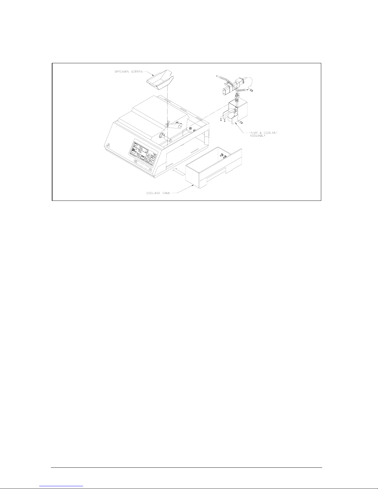
When Coolant/Lubricant is contaminated with abrasive residue or swarf, it
should be discarded and replaced.
1. To drain coolant; turn off unit, lift the hood, remove the blade and
flanges.
NOTE Retract arm to the far left position.
2. DISCONNECT THE POWER CORDS FROM THE CABINET.
3. Remove the Dressing Chuck Bracket and Coolant Assembly, and
Screen.
4. Lift the Coolant Tank at the handle and pull so that the tank slides
horizontally.
5. Thoroughly clean the Coolant Pump, Specimen Screen, Dressing
Chuck and Coolant Tank.
6. Slide the Coolant Tank back into the cabinet.
7. Place the components back into the tank as shown in Figure 8.
Cleaning the Unit
The ISOMET™ 2000 Precision Saw should be cleaned periodically to
prevent build-up of cutting residue and cutting fluids. Exterior painted
surfaces including the cutting chamber may be cleaned with non-abrasive
household cleaners.
MA112480-20 03/06/00
Connect the power cords into the correct connectors.
11
The protective hood and touch pad control panel should be cleaned using
mild soap and water applied with a soft cloth.
Figure 8 Tank Removal and Cleaning
MA112480-20 03/06/00
12

Figure 9 Parts Diagram for ISOMET™ 2000 Precision Saw
MA112480-20 03/06/00
13

Figure 10 Parts Diagram for ISOMET™ 2000 Precision Saw
MA112480-20 03/06/00
14

Figure 11 Parts Diagram for ISOMET™ 2000 Precision Saw
MA112480-20 03/06/00
15

Figure 12 Parts Diagram for ISOMET™ 2000 Precision Saw
MA112480-20 03/06/00
16

Figure 13 Parts Diagram for ISOMET™ 2000 Precision Saw
MA112480-20 03/06/00
17

Figure 14 Parts Diagram for ISOMET™ 2000 Precision Saw
MA112480-20 03/06/00
18

Figure 15 Parts Diagram for ISOMET™ 2000 Precision Saw
MA112480-20 03/06/00
19

Figure 16 Parts Diagram for ISOMET™ 2000 Precision Saw
MA112480-20 03/06/00
20

Figure 17 Parts Diagram for ISOMET™ 2000 Precision Saw
MA112480-20 03/06/00
21

Figure 18 Parts Diagram for ISOMET™ 2000 Precision Saw
MA112480-20 03/06/00
22

Figure 19 Parts Diagram for ISOMET™ 2000 Precision Saw
MA112480-20 03/06/00
23
POWER SUPPLY
R10095
L2
AC INPUT
85-264V
50/60HZ
L1
GND
N
L
G
STRAIN
GAUGE
TM1+
DC
OUT
TM2-
AC
IN
IEC
CONNECTOR
LINE
FILTER
R9838 (115V)
R9839 (220V)
ARM MOTOR
DRESSER MOTOR
RS232 PORT
2480S142
X1400
5
2
3
4
2480S204
20
21
+S
N/C
-S
N/C
FG
H
N
2480S236
15
16
17
1
1
3
N/C
2
N/C
4
5
N/C
2480S235
R88142480S231 2480S231
1
CIRCUIT
BREAKER
34
+-
A
2480S086
43
J10910
6 PIN
J10101
X1202
J11213
1 2 3 4
2480S228
SAW MOTOR
TACHOMETER
2
G/Y
B
W
18
B
19
W
G/Y
24
2480S139
CPU / ANALOG INTERFACE PCB
4
6
5
1
2
3
342 1
++
2480S217
X1103
AC HI VOLTAGE
X3100
2480S087
MICROMETER MOTOR
1234
J10304
2480S141
X3301
J3103
MICROMETER
X4201
TACHOMETER
1 2 3 4 5
1 2 4 8
J11112
J11011
J10614
J10910
6 PIN
12
N/C
--AA
X1304
R9856
2480S138
OPERATORS CONTROL PANEL
2480S232
2480S231
3
2
1
9
10
11
RED
GRN
BLK
MALE HOUSING 1180S133
MALE PINS R7042
FEMALE
HOUSING R7046
2480S147
3 N/C
7
6
5
2
1
1
23N/C
5
6
LIMIT SWITCHES
7
8
5
6
+
FAN
A
2480S148
-
+
PUMP MOTOR
A
2480S051
-
R8988
J4307
SAW BLADE MOTOR
X4105
2480S005
PART OF
MEMBRANE
2480S147
2480S147
2480S097
X5104
ARM UP
POSITION
ARM DOWN
POSITION
MICROMETER HOME
LID
OPEN
OPERATORS CONTROL
MEMBRANE PANEL
ISOMET 2000
PRECISION SAW
(2480900K.DSN)
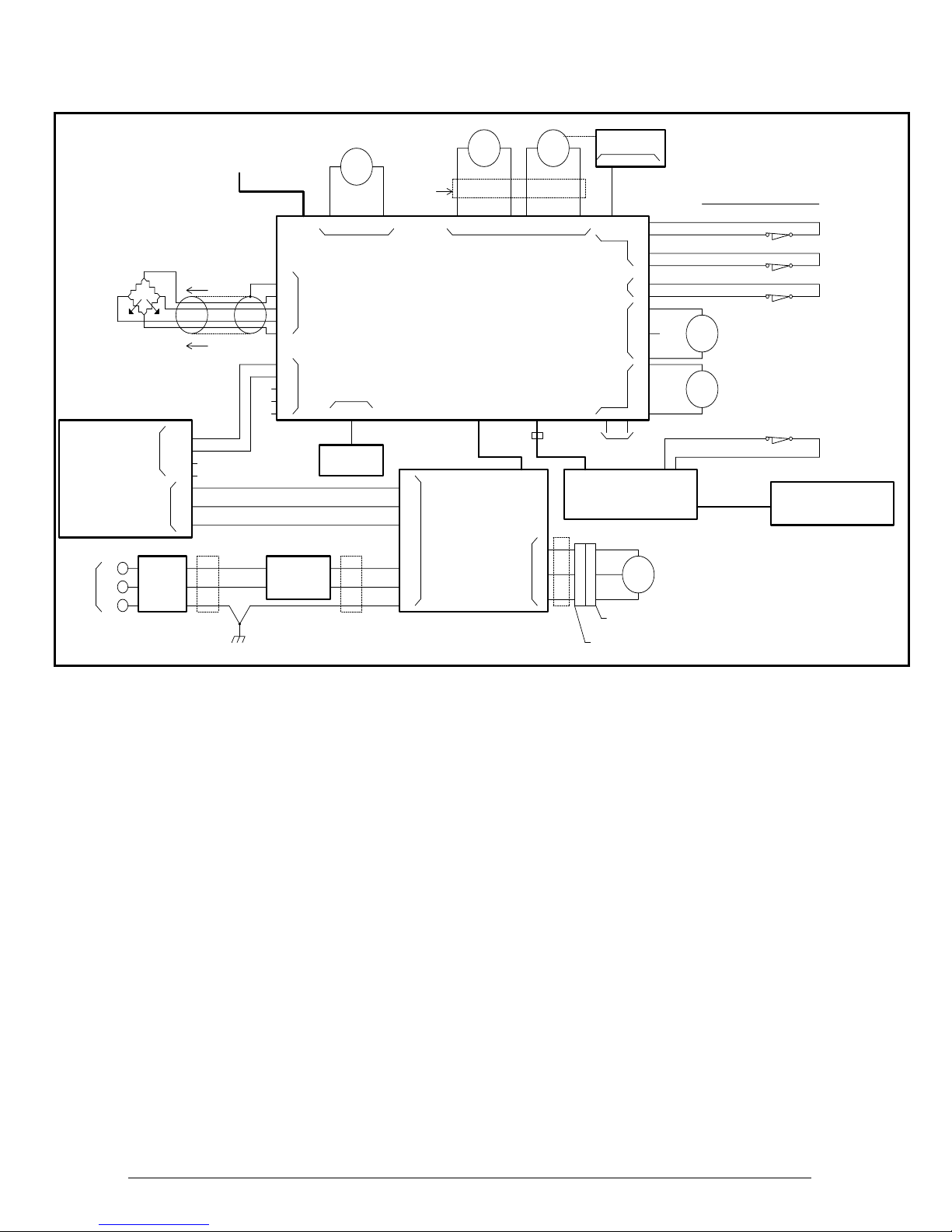
Figure 20 ISOMET™ 2000 Connection Diagram
MA112480-20 03/06/00
24

Figure 21 Parts Diagram for ISOMET™ 2000 Precision Saw
MA112480-20 03/06/00
25

ISOMET™ 2000 Precision Saw Parts List
PART
NUMBER DESCRIPTION QTY U/M
MA112480 MANUAL, INSTRUCT-ISOMET 2000 1.00 EA
MA112483 INSTR SHT, ISOMET PLUS CHUCK 1.00 EA
MA114207 SHEET,INSTRUCTION-7"C/O WHEELS 1.00 EA
R0585 TIE STRAP .10X4IN 8.00 EA
R0603 NUT 4-40 HEX SS 2.00 EA
R0603LW LOCK WASHER #4 STAINLESS STEEL 2.00 EA
R0603W WSHR,FLAT .125X.312X 04 STNSTL 4.00 EA
R0605LWE WSHR, EXT # 6 STN STL 4.00 EA
R0606LW LOCK WASHER #6 SS 2.00 EA
R0612LW LOCK WASHER #10 SS 12.00 EA
R0612W WASHER #10 SS 8.00 EA
R0615LW LOCK WASHER 1/4IN SS 8.00 EA
R0615W WASHER 1/4IN SS 1.00 EA
R0693 SCREW 8-32 1/2IN SKT HD SS 2.00 EA
R0962 SCREW 10-32 3/8IN SKT HD SS 2.00 EA
R0963 SCREW 10-32 1/2IN SKT HD SS 11.00 EA
R0965 SCREW 10-32 3/4IN SKT HD SS 4.00 EA
R0967 SCREW 10-32 1 IN SKT HD SS 1.00 EA
R0969 SCREW 10-32 1-1/4IN SKT HD SS 1.00 EA
R0984 SCREW 1/4-20 5/8IN SKT HD SS 2.00 EA
R0987 SCREW SKT HD 1/4-20 1 IN SS 3.00 EA
R10095 POWER SUPPLY, 12V DC 110W 1.00 EA
R10311 SCREW, 5/16-18 X 2-1/2 4.00 EA
R1185 SCREW SET 10-32 3/8IN 2.00 EA
R1273 SCREW SET 6-32 1/4IN SS 2.00 EA
R1281 SCREW SET 8-32 1/8IN SS 2.00 EA
R1293F SCREW SET 1/4-28 5/16IN SS NLC 1.00 EA
R1625 SCREW 6-32 3/8IN SLT RD HD SS 2.00 EA
R1652 SCREW 8-32 1-1/4IN SLT RDHD SS 4.00 EA
R2004 SCREW 4-40 1/2IN SLT OV HD SS 2.00 EA
R2408 SCREW 1/4-20 1-3/4IN HEX HD SS 4.00 EA
R2858 SPEC PLATE, BLANK - NON-C.S.A. 1.00 EA
R6106 CARTON, 4X3X3 200# OYS WHT 1.00 EA
R6159 16 OZ PVC CYL 1.00 EA
R6190 WHITE POLYPROP RIB CAP 1.00 EA
R6743 CARTON, BOOKFOLD 1.00 EA
R6744 PAD 2.00 EA
R6826 CARTON-ISOMET 2000 1.00 EA
R6826A BASE, PLYWOOD-ISOMET 2000 1.00 EA
R6827A PAD,HOLD DOWN 29.62X24.12X20.5 1.00 EA
R6827B PAD, TOP-ISOMET 2000 1.00 EA
R7042 PIN, MALE MOLEX 3.00 EA
R7079 LOCKNUT HEX - NYLON 21.00 EA
R7318 RETAINING RING EXT .25 SS 2.00 EA
R7414 SCREW, 10-32 X 5/8 IN CR PAN HD 1.00 EA
R7572 SCREW 6 x 7/16 CR PNHD NICKEL 2.00 EA
R7630 SCREW 6-32 3/4IN CR FLT HD SS 2.00 EA
R7654 SCREW 4-40 5/8IN CR RD HD SS 4.00 EA
R7745 CABLE TIE-MEDIUM 5.6 LG 4.00 EA
R7748 ADHESIVE CABLE MOUNT 2.00 EA
R7821 MAGNET-REEDSWITCH 1.00 EA
R7848 SCREW 6-32 3/4IN CR PAN HD SS 9.00 EA
R7855 NUT 1/4-28 HEX JAM SS 2.00 EA
MA112480-20 03/06/00
26

ISOMET™ 2000 Precision Saw Parts List
PART
NUMBER DESCRIPTION QTY U/M
R7861 ROLL PIN 1/16 X 7/16 1.00 EA
R7886 BUMPER RUBBER 5.00 EA
R7908 NUT 10-32 KEPS 6.00 EA
R7969 SCREW SKT HD 1/4-20 3/4 IN SS 4.00 EA
R7978 DOWEL PIN 1/8 X 1IN LONG 1.00 EA
R7979 WASHER .265 ID SS 2.00 EA
R8003 SCREW SET 10-32 5/8IN HFDG 2.00 EA
R8072 SCREW 1/4-20 7/8IN SKT HD SS 4.00 EA
R8086 SCREW 4-40 1/2IN CR PAN HD SS 4.00 EA
R8277 PLUG-HOLE .68 ID 3.00 EA
R8331 WSHR, FLAT .150X.32X.03 NYLON 2.00 EA
R8344 MOUNT-VIBRATION .31 ID 4.00 EA
R8370 MOUNT CABLE TIE 3.00 EA
R8512 SCREW 10-32 X 7/8 SKT HD CAP 4.00 EA
R8530 VALVE-BALL 1/4" FRAME 1.00 EA
R8579 TAPE PCB TRACK MOUNTING 14.00 IN
R8616 SCREW,HEX HD CAP 1/4-20X2-1/4 4.00 EA
R8681 WASHER, 1/4" INTERNAL-EXTERNAL 4.00 EA
R8744 NUT, HEX 1/4-20 HVY NYLON BLK 10.00 EA
R8814 CIRCUIT BREAKER, 10A 250V 1.00 EA
R8898 SCR,MA 4-40X1/4 SOC ST BO 4.00 EA
R8899 SCR,MA 0-80X1/4 SOC ST BO 5.00 EA
R8900 PIN, DOWEL-1/4 DIA X 1 ST NP 4.00 EA
R8902 CONNECTOR, AC POWER 1.00 EA
R8905 SCR,MA 0-80 X 3/8 SOC ST BO 2.00 EA
R8943 SCR, SS 4-40 X 1/8 SS 2.00 EA
R8944 SCR, SS 4-40 X 1/4 SS 4.00 EA
R8945 SCR, MA M2.5 X 16 SOC SS 3.00 EA
R8946 SCR, MA 4-40 X 3/8 SS 16.00 EA
R8972 ADAPTER, 3/4" FGHT X 1/4" MNPT 1.00 EA
R8975 CONN, SNAP-LOC M/HOSE-M/PIPE 1.00 EA
R8976 TUBING, VINYL 3/4" ID X 1" OD 2.00 IN
R8978 TEE, 1/4"FNPT 1.00 EA
R8979 CLAMP, 1" NYLON HOSE 2.00 EA
R8980 ADAPTER, 3/4" X 3/4" MGHT 1.00 EA
R8982 NUT, HEX 3/4-16 JAM SS 1.00 EA
R8983 HOSE, SNAP-LOC 1/4" SYSTEM 1.00 FT
R8985 NOZZLE, SNAP-LOC 1/4" 2.00 EA
R8986 FITTING, SNAP-LOC1/4" NPT 1.00 EA
R8987 PLUG, 1/4" NYLON SQ HD 1.00 EA
R8988 SWITCH, MAGNETIC REED 1.00 EA
R8995 TERMINAL, CRIMP .156 CENTER 8.00 EA
R8996 HOUSING,MOLEX 6 PIN.156 CENTER 1.00 EA
R8997 HOUSING,MOLEX 2 PIN.156 CENTER 1.00 EA
R9001 BUSHING, CORD .090-.265DIA BLK 1.00 EA
R9004 O-RING, 1/16" NOM. DIA. 7.00 EA
R9008A CORD, IEC POWER - U.S 0.00 EA
R9008B CORD, IEC POWER - EUROPE 0.00 EA
R9008C CORD, IEC POWER - U.K 0.00 EA
R9008D CORD, IEC POWER - JAPAN 0.00 EA
R9017 SCR, MA 6-32 X .50 SOC SS 3.00 EA
R9019 SPACER, .15IDX.25ODX.38LG CPVC 14.00 EA
R9022 SCR, MA 4-40 X .75 BH NY 3.00 EA
MA112480-20 03/06/00
27

ISOMET™ 2000 Precision Saw Parts List
PART
NUMBER DESCRIPTION QTY U/M
R9031 WASHER, EXT 1/4X.50X.03 SS 7.00 EA
R9032 SCR, MA 1/4-20X1 RD NL-BLK 6.00 EA
R9033 SCR, MA 1/4-20X3/4 RD NL-BLK 4.00 EA
R9052 NIPPLE, 1/4" NPT X 2" LONG SS 1.00 EA
R9054 SCR, MA 4-40X3/8 PN NL-BLK 4.00 EA
R9055 SCR, MA ¼ -20X ½ RD NL-BLK 4.00 EA
R9064 NIPPLE, CLOSE ¼ NPT NYLON BL 1.00 EA
R9069 WSHR, FLAT .25X.50X.125 NY BLK 4.00 EA
R9088 CONNECTOR, PLUG-IN 3 PIN 1.00 EA
R9089 CONNECTOR, PLUG-IN 6 PIN 1.00 EA
R9184 BEARING, .25 ID X .25 NYLON 1.00 EA
R9200 WASHER, .26ID X .38OD X .031 2.00 EA
R9311 SCR, MA 10-32X2.0 PN ST ZN 4.00 EA
R9327 PLASTIC, CASTING CASTOLITE-AP 1.00 OZ
R9532 SPRING, .36 OD x 1.75 LONG 1.00 EA
R9536 SCR, 6-32 X ¼ SOC STN STL 4.00 EA
R9561 SCR, MA 6-32 X 2 PN CR SS 2.00 EA
R9760 WRENCH, OPEN END 1/2 - 5/8 IN 1.00 EA
R9776 CABLE, BRAIDED SHIELDING 1.25 FT
R9810 TAPE, EMI/RFI SHIELDING 1.5 WIDE 9.00 IN
R9838 FILTER, LINE 10 AMP W/IEC SOCKET 1.00 EA
R9839 FILTER, LINE 6 AMP W/IEC SOCKET 1.00 EA
R9856 SUPPRESSOR, 34-40 RIBBON CABLE 1.00 EA
AK#207 ACCESSORY KIT F/112280/112480 1.00 EA
1180S72 NUT 6-32 KEPS 7.00 EA
1180S97 5/32 INCH HEX WR.CD.PL 1.00 EA
1180S133 MOLEX, 3 PIN MALE PLUG 1.00 EA
1186S001 GLUE CHUCK 1.00 EA
1751P076 CIRCUIT BREAKER, SPEED SENSOR 1.00 EA
1790S062 PLATE, BILINGUAL CAUTION 2.00 EA
1950S054 SWITCH, LIMIT-TOP 1.00 EA
1950S056 SWITCH, LIMIT-BOTTOM 1.00 EA
2280S031A PULLEY, .312 BORE 1.00 EA
2280S031B PULLEY, .500 BORE 1.00 EA
2280S057 FLANGE 4 INCH 2.00 EA
2280S110 BUSHING-SHAFT END ANODIZED 1.00 EA
2280S120 SCREW THUMB 10-32 X .31 1.00 EA
2280S123 LABEL-DRAIN ISOMET + 2.00 EA
2280S124 LABEL-OVERFLOW ISOMET+ 2.00 EA
2280S125 LABEL-EXT FLUID ISOMET+ 2.00 EA
2280S169 HINGE, ISOMET 2000 1.00 EA
2480S005 MOTOR, .4 HP 90 VDC 1.00 EA
2480S013 BASEPLATE,ISOMET 2000 1.00 EA
2480S029 COVER, MIC-ADJUSTMENT 1.00 EA
2480S033 BRACKET, MAIN 1.00 EA
2480S034 BOOT, MIC-MOTOR 1.00 EA
2480S036 BRACKET, MIC LIMIT 1.00 EA
2480S037 HUB AND SLINGER 1.00 EA
2480S038 SPACER 1.00 EA
2480S039 SLINGER, ARM 1.00 EA
2480S040 COVER, MIC-MOTOR 1.00 EA
2480S041 BELT, TIMING 1.00 EA
2480S042 ENCODER, ROTARY H.P. HEDS-5500 1.00 EA
MA112480-20 03/06/00
28

ISOMET™ 2000 Precision Saw Parts List
PART
NUMBER DESCRIPTION QTY U/M
2480S043 MOTOR, D.C. 1 RPM 40 IN.LB. T 1.00 EA
2480S044 MOTOR, D.C. 120 RPM 1 IN.LB. T 1.00 EA
2480S045 HOOD, ISOMET 2000 1.00 EA
2480S046 BRACKET, DRESSING CHUCK 1.00 EA
2480S047 COUPLING, TANK BULK-HEAD 3.00 EA
2480S050 LABEL, DRESS CHUCK-ISOMET 2000 1.00 EA
2480S051 PUMP ASSEMBLY 1.00 EA
2480S053 PUMP, COOLANT 12 VDC 1.00 EA
2480S054 PUMP AND COOLANT ASSEMBLY 1.00 EA
2480S055 GUIDE, DRESSING CHUCK 2.00 EA
2480S057 CLAMP, DRESSING CHUCK 1.00 EA
2480S059 COVER, FRONT 1.00 EA
2480S060 COVER, MIDDLE 1.00 EA
2480S061 LABEL, PUMP-ISOMET 2000 1.00 EA
2480S062 LABEL, POWER-ISOMET 2000 1.00 EA
2480S065 GUARD, SLINGER 1.00 EA
2480S066 CONNECTOR, TANK-PUMP 1.00 EA
2480S070 TANK, REMOVABLE 1.00 EA
2480S072 SAW HOUSING ASSEMBLY 1.00 EA
2480S074 CONNECTOR, CABINET-PUMP 1.00 EA
2480S078 GEAR, MITER-MACHINED 1.00 EA
2480S081 CABINET, UPPER - ISOMET 2000 1.00 EA
2480S082 CABINET, LOWER - ISOMET 2000 1.00 EA
2480S083 SPECIMEN ARM ASSEMBLY 1.00 EA
2480S084 THUMB SCREW ASSEMBLY 1.00 EA
2480S085 MOTOR, DRESSING CHUCK 1.00 EA
2480S086 DRESSING CHUCK ASSEMBLY 1.00 EA
2480S087 PCB, HIGH VOLTAGE 1.00 EA
2480S096 THUMB SCREW ASSEMBLY 1.00 EA
2480S097 MIC-SWITCH ASSEMBLY 1.00 EA
2480S114 CLAMP, SINGLE SADDLE 0.00 EA
2480S115 CHUCK, SINGLE SADDLE 0.00 EA
2480S135 CONNECTOR, SPIGOT 1.00 EA
2480S138 CABLE, OPER CONTROL/CPU ANALOG 1.00 EA
2480S139 HARNESS, CPU ANALOG/MOTORS 1.00 EA
2480S141 CABLE, CPU ANALOG/HIGH VOLTAGE 1.00 EA
2480S142 CABLE, RS232/CPU ANALOG 1.00 EA
2480S147 HARNESS, CPU ANALOG/ENCODER 1.00 EA
2480S148 FAN ASSEMBLY 1.00 EA
2480S149 CONNECTOR, CABINET-DRESSER 1.00 EA
2480S150 CONNECTOR, TANK-DRESSER 1.00 EA
2480S153 SCREEN, SPECIMEN 1.00 EA
2480S154 GASKET, DRESSING CHUCK 3.00 EA
2480S155 GASKET, ARM SLINGER 1.00 EA
2480S156 GASKET, GUARD SLINGER 1.00 EA
2480S157 HOOD ASSEMBLY 1.00 EA
2480S158 SPACER, HINGE 3.00 EA
2480S164 WIRE, JUMPER-2" 20 GAUGE BLK 1.00 EA
2480S166 STOP,HOOD 3.00 EA
2480S172 STIFFENER, HOOD 1.00 EA
2480S175 HINGE, ISOMET 2000 3.00 EA
2480S176 BLOCK, DRESSING 1.00 EA
2480S179 KIT, ACCESS-WRENCH 1.00 EA
MA112480-20 03/06/00
29

ISOMET™ 2000 Precision Saw Parts List
PART
NUMBER DESCRIPTION QTY U/M
2480S180 FILM, MYLAR 1.00 EA
2480S181 WASHER, 1.0IDX1.5ODX.19TH FELT 1.00 EA
2480S185 SHIELD, HOOD 1.00 EA
2480S186 SCREW, LH DRESSING CHUCK 1.00 EA
2480S187 COUPLER, SCREW DRESSING CHUCK 1.00 EA
2480S190 LABEL, CAUTION ARM 1.00 EA
2480S191 BODY, DRESSING CHUCK 1.00 EA
2480S192 ELBOW, SPEC 1.0 TUBE x 1/2 TUBE 1.00 EA
2480S193 NIPPLE, 1/2 NPT x 3.0 PVC 1.00 EA
2480S197 PLATE, LIMIT SWITCH 1.00 EA
2480S198 SHAFT, ARM 1.00 EA
2480S203 SCREW, MIC ADJUSTMENT 1.00 EA
2480S204 GAUGE, STRAIN ISOMET 2000 1.00 EA
2480S205 ARM HOUSING ASSEMBLY 1.00 EA
2480S206 MOTOR, D.C. 1RPM 40 IN/LBS T 1.00 EA
2480S207 BRACKET, ANGLE STRAIN GAUGE 1.00 EA
2480S208 PUMP & COOLANT ASSEMBLY 1.00 EA
2480S209 PLATE, STRAIN GAUGE MOUNT 1.00 EA
2480S210 BRACKET, DRESSING CHUCK 1.00 EA
2480S211 LEVER, GEAR MOTOR 1.00 EA
2480S213 ROD, 1/4-28 x 2.0 LG SS THREADED 1.00 EA
2480S217 PCB, CPU/ANALOG INTERFACE 1.00 EA
2480S219 SCREW, THUMB 1.00 EA
2480S221 SCREEN, .125 HOLES POLYPROP 1.00 EA
2480S222 SPACER, HINGE 3.00 EA
2480S226 BRACKET, SPD SENSOR 1.00 EA
2480S227 PLATE, SPEC ISOMET 2000 EC 1.00 EA
2480S228 SENSOR ASSEMBLY, SPEED 1.00 EA
2480S229 CABINET, UPPER-ISOMET 2000 EC 1.00 EA
2480S230 CABINET, LOWER ISOMET 2000 EC 1.00 EA
2480S231 HARNESS, CIRC BKR/EMI FILTER 1.00 EA
2480S232 PCB, OPERATORS CONTROL 1.00 EA
2480S233 NAMEPLATE,ISOMET 2000 MEMBRANE 1.00 EA
2480S235 CABLE, CPU ANALOG/POWER SUPPLY 1.00 EA
2480S236 HARNESS, HV BOARD/POWER SUPPLY 1.00 EA
2480S237 BRACKET, L SHAPE 1.00 EA
111186 CHUCK-WAFERS 1.00 EA
111198 DRESSING BLOCK SPACER KIT 1.00 EA
112282 FLANGE SET 3" SET OF 2 1.00 EA
112293 ISOCUT PLUS FLUID BULK 0.13 GL
112487 SINGLE SADDLE CHUCK 1.00 EA
112491 SMALL DOVETAIL CHUCK ASSEMBLY 1.00 EA
114276 WAFERING BLADE 6X.020X1/2 15LC 1.00 EA
112293016 ISOCUT PLUS FLUID - PINT 1.00 EA
114207001 CUT-OFF WHEEL 7X0.030 X 1/2 10.00 EA
114207010 CUT-OFF WHEELS 7X.030X1/2 0.20 EA
114217001 CUT-OFF WHEEL 7X0.030 X 1/2 10.00 EA
114217010 CUT-OFF WHEELS 7X.030X1/2 0.20 EA
MA112480-20 03/06/00
30

ISOMET™ 2000 Accessories and Supplies
Blades
ISOMET™ 2000 Wafering Blades
Blade Type 4″ dia.
Series 20 HC
Diamond,
high concentration
Series 15 HC
Diamond,
high concentration
Series 20 LC
Diamond,
low concentration
Series 15 LC
Diamond,
low concentration
Series 10 LC
Diamond,
low concentration
Series 5 LC
Diamond,
low concentration
Thickness 5″ dia.
(10.2 cm)
11-4215 .020″
11-4244 .012″
(0.3 mm)
11-4225 .020″
11-4254 .012″
(0.3 mm)
11-4285 .015″
11-4295 .015″
(12.7 cm)
11-4245 .015″
11-4255 .015″
Thickness 6″ dia.
(0.5 mm)
(0.4 mm)
(0.5 mm)
(0.4 mm)
(0.4 mm)
(0.4 mm)
Thickness 7″ dia.
(15.2 cm)
11-4237 .025″
11-4246 .020″
(0.5 mm)
11-4227 .025″
11-4276 .020″
(0.5 mm)
11-4287 .020″
(18.8 cm)
11-4247 .025″
11-4277 .025″
Thickness
(0.64 mm)
(0.63 mm)
(0.64 mm)
(0.64 mm)
(0.5 mm)
ISOCUT® Wafering Blades
Low concentration 11-4264 .012″
(0.3 mm)
11-4265 .015″
(0.4 mm)
11-4266 .020″
Abrasive Cut-off Wheels
For ferrous
materials
For tough non-
ferrous materials
* Use 1/2″ x 1/2″ x 3″ (13mm x 13mm x 76mm) Dressing Stick, Part Number 11-1190
for coarse series 20 & 15, or 11-1195 for fine series 10 & 5 Blades.
(0.5 mm)
11-4267 .025″
(0.6 mm)
11-4207-010
11-4207-010
.030″
(0.8 mm)
.030″
(0.8 mm)
MA112480-20 03/06/00
31

ISOMET™ 2000 Accessories and Supplies
Accessories
Part No. Description
11-1191
11-1197 FLANGES, 2.5” (64mm) DIA. set of two for use with larger diameter blades where greater depth of cut is
11-2282
11-2283
11-2284
11-2481 GONIOMETER, for precision sectioning of samples along specific planes, each axis provides monument in
11-2482
11-2483
11-2484
11-2485 IRREGULAR SPECIMEN CHUCK, for irregularly shaped samples.
11-2486 THIN SECTIONS AND WAFER CHUCK, for wafers, single crystals and thin sections.
11-2487
11-2488
11-2489
11-2491
11-2492
11-2493 EXTERNAL RECIRCULATING KIT.
11-2494 BONE CHUCK, for gripping bones and other irregularly shaped specimens.
11-1189
FLANGES, 1-3/4″ (44 mm) dia., recessed, set of two for use with larger specimens where greater depth of
cut is required.
required.
FLANGES, 3″ (76 mm) dia., set of two for use with larger diameter blades where greater depth of cut is
required.
FLANGES, 4″ (102mm) dia., set of two for use with larger diameter blades when higher cutting speed and
additional blade support is required.
FLANGES, 5″ (127 mm) dia., set of two for use with larger diameter blades where maximum cutting speed
and blade support is required.
2″ increments.
FASTENER CHUCK, 1-1/8″ - 2-1/8″ (29mm - 54mm) length capacity, for longitudinal sectioning of
fasteners, tubes and solid cylinders.
DOUBLE SADDLE CHUCK, 1-3/8″ (35mm) dia. capacity, prevents possible damage to specimen by
holding sectioned portion firmly after cutting is completed.
GLASS SLIDE CHUCK, 1-1/8″ W x 1-7/8″ L (29mm x 46 mm) capacity, for thin sectioning of specimens
mounted to a glass slide.
SINGLE SADDLE CHUCK, 1-1/4″ (32 mm) diameter capacity, for bar and tube stock.
GLASS SLIDE CHUCK, 2″ W x 3″ L (51 mm x 76 mm) capacity, for thin sectioning of specimens mounted
to a glass slide.
MOUNTED SPECIMEN CHUCK, 1-1/2″ (38 mm) diameter capacity for mounted samples.
DOVETAIL CHUCK, 1-1/4″ (32 mm) for rigid mounting of solid stock.
DOVETAIL CHUCK, 1-1/2″ (38 mm) diameter capacity for rigid mounting of solid bar stock.
MOUNTED SPECIMEN CHUCK, 1″ (25 mm) or 1-1/4″ (32 mm) diameter capacity for mounted samples.
Supplies
Part No. Description
11-2293-016 ISOCUT® PLUS FLUID, pint, combination lubricant/coolant concentrate for use with ISOMET™ 2000
11-2490
11-2495
11-2496 ISOMET™ 2000 Chuck Padding, PSA backed.
Precision Saw.
DRESSING STICK for ISOMET™ 2000, 1″ x 1/2″ x 3″ (25 mm x 13 mm x 76 mm) For Series 20 and 15
Diamond Wafering Blades.
DRESSING STICK for ISOMET™ 2000, 1″ x 1/2″ x 3″ (25 mm x 13 mm x 76 mm) For Series 10 and 15
Diamond Wafering Blades.
MA112480-20 03/06/00
32

ISOMET™ 2000 Accessories and Supplies
ISOMET™ 2000 Precision Saw Application Guide
Specimen Material Blade Type Speed Applied Load
Turbine blades - ferrous 11-4207 Abrasive wheel 3500 rpm 300-500 grams
Turbine blades - non-ferrous 11-4217 Abrasive wheel 3500 rpm 200-500 grams
Thermal Spray Coatings:
Ceramics 11-4207 or Series 15 HC diamond
Metallic - ferrous 11-4207 Abrasive wheel
Metallic - non-ferrous 11-4217 Abrasive wheel
Abradable 11-4207 Abrasive wheel
Titanium (bar stock, 1″ dia.)
Aluminum (bar stock, 1″ dia.)
Mild Steel (bar stock, 1″ dia.)
Printed circuit boards 11-4207 or Series 15 HC diamond 2000 rpm 200 grams
Tungsten carbide (1/2″ triangle x 1/4″ thick)
Hot pressed silicon nitride, Si3N4 Series 15 LC diamond 4000 rpm 800 grams
Boron carbide, B4C Series 20 LC diamond 3500 rpm 700 grams
Sapphire, Al2O3 Series 15 LC diamond 1500 rpm 300 grams
Chromium doped sapphire, Al2O3 Series 15 LC diamond 2500 rpm 500 grams
Partially stabilized zirconia, ZrO2 Series 15 LC diamond 2500 rpm 500 grams
Silicon carbide, SiC Series 15 LC diamond 2500 rpm 500 grams
Tungsten carbide 6% cobalt binder, WC Series 15 HC diamond 4000 rpm 800 grams
Tungsten carbide 25% cobalt binder, WC Series 15 HC diamond 4500 rpm 900 grams
High purity fused silica, SiO2 Series 10 LC diamond 1500 rpm 300 grams
Extruded alumina, Al2O3 Series 10 LC diamond 2500 rpm 500 grams
Aluminum nitride, AlN Series 10 LC diamond 3000 rpm 600 grams
Nickel zinc ferrite, Mo. Fe2O3 Series 10 LC diamond 1500 rpm 300 grams
Manganese zinc ferrite, Mo. Fe2O3 Series 10 LC diamond 1500 rpm 300 grams
Yttria alumina garnet, "YAG" Series 10 LC diamond 2500 rpm 500 grams
Chrysocolla (copper ore), hydrous copper
silicate
Gray Cast Iron 11-4207 Abrasive wheel 2500 rpm 800 grams
Zinc 11-4217 Abrasive wheel 3500 rpm 800 grams
Hastelloy 11-4207 Abrasive wheel 3500 rpm 800 grams
White Cast Iron ISOCUT(R) Wafering blade 2500 rpm 700 grams
Stainless Steels 11-4207 Abrasive wheel 4000 rpm 350 grams
Magnesium 11-4217 Abrasive wheel 2500 rpm 800 grams
PC Boards 11-4217 Abrasive wheel 2500 rpm 500 grams
Titanium 11-4217 Abrasive wheel 2500 rpm 800 grams
Plastics 11-4217 Abrasive wheel 2500 rpm 500 grams
Aluminum 11-4217 Abrasive wheel 2500 rpm 600 grams
Brass 11-4217 Abrasive wheel 2500 rpm 600 grams
Thermal Spray Coatings 15 HC Diamond blade 3000 rpm
11-4207 Abrasive wheel
Turbine Blades 15 HC Diamond blade 2500 rpm 600 grams
11-4207 Abrasive wheel 2500 rpm 600 grams
11-4217 Abrasive wheel 3500 rpm 650 grams
11-4217 Abrasive wheel 2500 rpm 500 grams
11-4207 Abrasive wheel 4000 rpm 600 grams
Series 15 HC diamond 3500 rpm 400-600 grams
Series 10 LC diamond 3000 rpm 600 grams
3000 rpm 200 grams
3000 rpm 200 grams
2500 rpm 200 grams
2500 rpm 200 grams
2500 rpm 700 grams
MA112480-20 03/06/00
33

NOTES
MA112480-20 03/06/00
34
 Loading...