

Page 1

8
Environmental Protection / Disposal
8 Environmental Protection / Disposal
Environmental protection is one of the fundamental company policies of
the Bosch Group.
Quality of products, efficiency and environmental protection are equally
important objectives for us. Environmental protection laws and
regulations are strictly observed.
To protect the environment, we use the best possible technology and
materials, taking into account economic points of view.
Packaging method
For the packaging, we participate in the country-specific recycling
systems, which guarantees optimal recycling.
All packaging materials used are environmentally-friendly and
recyclable.
Old appliances
Old appliances contain materials that should be recycled.
The relevant assemblies are easy to separate, and all plastics are
identified. This allows the various components to be sorted for
appropriate recycling or disposal.
9 Boiler inspection and maintenance
Note the following when performing preventive maintenance:
DANGER: Danger to life from electric shock!
▶ When performing maintenance, label all connection
cables before disconnecting them.
▶ If cables are connected incorrectly, the system may
not operate correctly, with possibly dangerous
consequences.
▶ Always check that the heating system is working properly after
carrying out any maintenance work.
9.1 Why is regular maintenance important?
Heating systems must be serviced annually for the following
reasons:
• To maintain high efficiency Economical operation (low fuel
consumption)
• To achieve a high level of operational safety
• To maintain the cleanest combustion
• To ensure reliable operation and a
• Long service life
Maintenance work must be carried out only by a trained and certified
installer or service company. When replacing components, only Bosch
approved Buderus components may be used. The system should be
serviced annually. The results of the inspection must be recorded in the
maintenance log ( Chapter 9.8, page 35).
Spare parts can be ordered from Bosch with the aid of
the parts list.
9.2 Checking the flue gas system, combustion air supply,
air inlet and ventilation openings
▶ Check the flue gas system, including the combustion air supply.
▶ Check air inlet and ventilation openings.
▶ Remedy any defects immediately.
▶ Make sure that the combustion air supply and the ventilation
openings are not blocked at any point.
9.3 Inspection of the boiler and burner
▶ Perform a visual inspection of the boiler and burner for external dirt
accumulation.
▶ If dirt is found, clean boiler and burner.
Logano G334X – 6 720 811 237 (2017/02)28
Page 2

9.4 Preparing the boiler for cleaning
DANGER: Risk of fatal injury from electric current when
appliance is opened up!
▶ Before opening the boiler:
Disconnect heating system from the power supply
via the ON/OFF switch or the appropriate building
fuse.
▶ Take measures to ensure that the heating system
cannot be accidentally reactivated.
WARNING: Risk of fire from foreign objects!
Foreign objects between the main orifice and burner rod
inlet opening can cause a fire.
▶ Ensure that there are no objects at this location.
▶ When working on an open boiler: Secure appliance
components and cables to prevent them from getting
between the openings during operation.
▶ Shut down the heating system ( Chapter 7.1, page 27).
Removing the front wall of the boiler ( Fig. 38):
▶ Unscrew the locking screws [2] at the bottom of the front wall of the
boiler.
▶ Tilt the front wall of the boiler [1] forward and lift it out.
1
Boiler inspection and maintenance
9
1
7 747 014 639-30.2T
Fig. 39 Gas valve in OFF position
[1] ON/OFF knob (OFF position)
9.5 Cleaning the boiler
The boiler can be cleaned with brushes and/or by wet cleaning. Cleaning
tools are available as accessories.
9.5.1 Cleaning the boiler with brushes (mechanical cleaning)
Remove burner:
DANGER: Danger to life from electric shock!
If cables are connected incorrectly, the system may not
operate correctly, with possibly dangerous
consequences.
▶ When performing maintenance, label all connection
cables before disconnecting them.
▶ Always check that the heating system is working
properly after carrying out any maintenance work.
2
Fig. 38 Removing the front wall of the boiler
[1] Front wall of boiler
[2] Locking screws
DANGER: Risk of fatal injury from explosion of
flammable gases!
▶ Operations on the gas lines may be carried out only
by properly licensed gas contractors.
▶ Wait five (5) minutes until all gas has dissipated.
Check whether there is any smell of gas, including at
floor level. If you smell gas: STOP!
Check that the gas shutoff valve is closed. Repeat the
odor test. If you do not smell gas, proceed to the next
step.
▶ Turn the gas valve ON/OFF knob [1] clockwise to the OFF position.
Do not use excessive force.
6 720 810 547-35.1T
DANGER: Risk of fatal injury from electric current when
appliance is opened up!
▶ Before opening the boiler:
Disconnect the heating system from the electrical
power supply by means of the emergency shutoff
switch or the appropriate building fuse.
▶ It is not sufficient just to switch off the controller.
▶ Take measures to ensure that the heating system
cannot be accidentally reactivated.
▶ Disconnect the heating system from the power supply.
▶ Close the gas main shutoff valve.
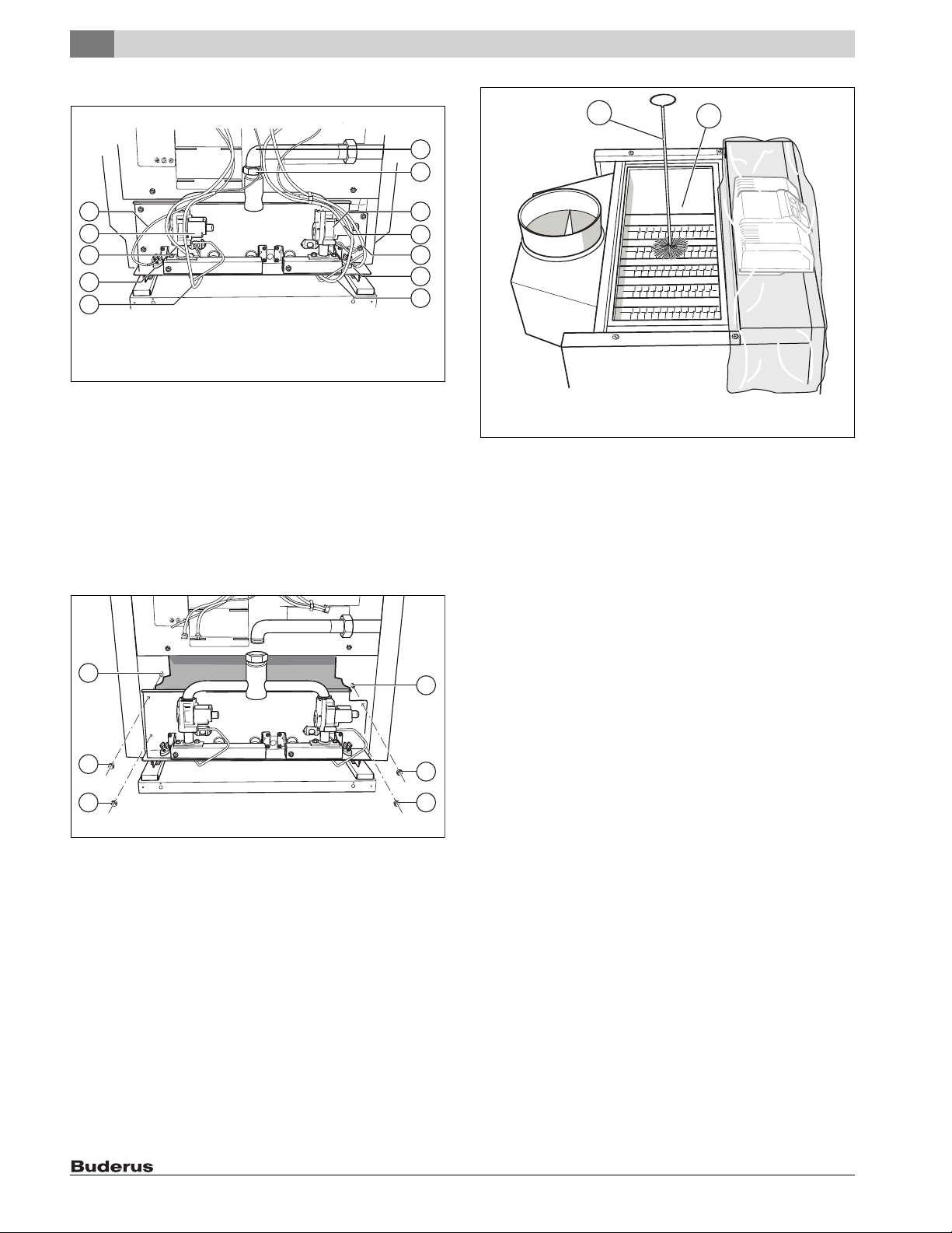
▶ Disconnect pilot gas line [6] from the gas valve [8].
▶ Disconnect high-tension ignition lead [3] from the burner controller.
▶ Tie gas line [2] with wire or cord (secure).
▶ Loosen the retaining screw [1] on the gas feed line.
▶ Check the gasket for damage. Replace damaged gasket. Keep the
gasket in a safe place.
▶ Label wires of flame roll-out safety shutoff switch [4] and disconnect
them from the switch [5].
Logano G334X – 6 720 811 237 (2017/02) 29
Page 3
9
Boiler inspection and maintenance
▶ Disconnect connection lines to the gas valve [7].
1
2
6
7
5
4
3
2
1
6 720 810 547-16.1T
Fig. 40 Removing the burner
[1] High-tension ignition lead
[2] Flame roll-out safety shutoff switch
[3] Connection cable to gas valve
[4] Gas valve
[5] Connection cable to flame roll-out safety shutoff switch
[6] Gas supply line
[7] Union on gas supply line
▶ Loosen retaining nuts [1] on the burner shield. Pull the burner out
straight.
▶ Make sure that the spacers [2] remain on the studs.
4
5
3
2
1
6 720 810 547-36.1T
Fig. 42 Cleaning the hot gas flues
[1] Cleaning Brush
[2] Thermal insulation
2
1
1
6 720 810 547-17.1T
Fig. 41 Removing the burner
[1] Retaining nuts
[2] Studs with spacers
Cleaning the boiler:
▶ Remove the boiler casing and thermal insulation; check for damage.
▶ Unscrew cleaning cover from the draft diverter.
▶ Use cleaning brushes to brush out hot gas flues.
To prevent entry of metal dust into the control unit:
▶ Cover controller with foil.
▶ Clean combustion chamber and bottom panel.
▶ Screw cleaning cover into place and replace thermal insulation.
▶ Install boiler casing.
2
1
1
Logano G334X – 6 720 811 237 (2017/02)30
Page 4

Boiler inspection and maintenance
9
9.5.2 Wet cleaning the boiler (chemical cleaning)
For wet cleaning use a cleaning agent appropriate for the degree of
soiling (soot or scale).
Follow the same procedure as for cleaning with brushes
( Chapter 9.5.1, page 29).
Observe the operating instructions of the cleaning agent.
Under some circumstances you may have to proceed
differently from the method described here.
▶ Remove the boiler casing and thermal insulation, check for damage.
▶ Unscrew cleaning cover from the draft diverter.
To prevent entry of metal dust into the control unit:
▶ Cover controller with foil.
▶ Ventilate boiler room well.
▶ Spray cleaning agent evenly into the hot gas flues.
▶ Carry out the burner assembly and installation in reverse order to
their removal and disassembly ( page 29).
9.6 Cleaning of burner
▶ Remove the burner ( page 29).
▶ Check burner rods for dirt.
If necessary:
▶ Clean burner as described below.
▶ Unscrew pilot burner unit [1] from burner.
▶ Disconnect pilot gas line [3] from pilot burner unit.
▶ Remove and blow out pilot orifice [2].
▶ Immerse burner rods in water with cleaning agent and brush off.
Make sure that the thermal insulation on the burner
shield does not get wet.
6 720 645 166-24.1T
Fig. 43 Wet cleaning the boiler
▶ Check the gasket for damage.
▶ Replace damaged gasket.
▶ Place the heating system in operation.
▶ Heat the boiler to a temperature of at least 122 °F (55 °C).
▶ Shut down the heating system.
▶ Allow boiler to cool.
▶ Remove the burner ( page 29).
▶ Brush out the hot gas flues.
▶ Clean combustion chamber and bottom panel.
▶ Ventilate boiler room well again.
▶ Install or clean the burner ( page 31).
▶ Screw cleaning cover into place and replace thermal insulation.
▶ Install boiler casing.
Fig. 44 Pilot burner
[1] Pilot assembly
[2] Pilot orifice
[3] Pilot gas line
[4] Igniter sensor cable
▶ Rinse off the burner rods under a stream of water. Hold burner so that
water enters all slots of the burner rods and drains out again.
▶ Remove remaining water by swinging the burner.
▶ Check that the burner rods are free.
▶ Remove water and dirt residue in the slots.
If slots are damaged:
▶ Replace the burner.
Logano G334X – 6 720 811 237 (2017/02) 31
Page 5

9
Boiler inspection and maintenance
Fig. 45 Swinging the burner
▶ Carry out the burner assembly and installation in reverse order to
their removal and disassembly ( page 29).
▶ Replace gaskets if necessary.
▶ Place boiler in operation as directed in Chapter 6, starting on
page 20.
▶ Check the functioning of the aquastat.
▶ Check low water indicator if one is installed.
▶ Check area around boiler for hazards.
The area around the boiler must be free from flammable substances,
gasoline or any other flammable or corrosive vapors and liquids.
▶ Complete the maintenance log to confirm that all maintenance work
has been carried out ( Chapter 9.8, page 35). Sign the
maintenance log and familiarize the owner with how the heating
system operates.
Logano G334X – 6 720 811 237 (2017/02)32
Page 6

9.7 Troubleshooting the G334X
Required material:
• Circuit diagrams ( page 36)
• Voltmeter 120 VAC and 24 VAC
Start
Boiler inspection and maintenance
9
Close gas valve. Set thermostat
(control) to require heat (flue
baffle open).
Switch on power.
Observe ignition sparks in gap
between electrode and sensor
through sight glass.
Open main gas valve. Pilot flame
is burning.
Ignition spark stops as soon as
pilot flame burns.
Main burner ignites.
No
No
No
No
No
Check electrical power supply, low-voltage transformer, thermostat
•
(control) and wiring. Check that the vent damper (if installed) is open and
the limit switch is present.
On models with vent damper check that it operates and lmit switches are
•
present. If necessary, replace vent damper.
Check ignition wiring, ceramic insulator of ignition electrode and ignition
•
gap, adjust if necessary.
Check the ignition cable contact for signs of scorching or kinking.
•
Replace automatic ignition unit.
•
Check that all manually operated dampers are open; check that gas
•
connections and pressures are correct and that ignition gas orifice are not
blocked.
Check electrical connection between automatic ignition and ignition timer
•
on the gas valve.
Use MV-MV/PV terminals to check 24 V alternating current at the
•
automatic ignition. If the voltage is correct replace gas valve, otherwise
replace automatic ignition module.
Check ignition wiring and ground for continuity.
•
Check ignition electrode.
•
Check electrical connections between ignition electrode and automatic
•
ignition.
Check whether the ceramic insulator in the ignition electrode is broken.
•
Check that the pilot flame surrounds the electrode and burns steadily with
•
a bluish flame.
Adjust pilot flame.
•
If this does not correct the fault, replace the automatic ignition unit
•
module.
Use MV-MV/PV terminals to check 24 V alternating current, closed
•
current circuit at the automatic ignition. If there is no voltage, replace
automatic ignition.
Check electrical connection between automatic ignition module and gas
•
valve. If OK, replace gas valve.
Check ignition wiring and ground for continuity. Note: If the ground is
System operates until the heat
requirement ends.
Heat requirement ended, system
switches off, vent damper
closes.
End of troubleshooting Repeat procedure until heating system operates correctly.
No
No
•
weak or faulty, the system may switch off at random, even if the heating
system operates correctly when checked.
Check that the pilot flame surrounds the electrode and burns evenly with
•
a bluish flame. If OK replace electrode.
If everything is OK replace automatic ignition module.
•
Check operation of thermostat (control).
•
Disconnect 24-V connection to gas valve. If gas valve closes, check
•
thermostat and connection line again.
If the gas valve does not close, replace gas valve.
•
Fig. 46 Troubleshooting the G334X
Logano G334X – 6 720 811 237 (2017/02) 33
Page 7

9
Boiler inspection and maintenance
START
PHASE 1
Ignition attempt
Room thermostat (control) signals heat requirement
Vent damper (if installed) opens.
Ignition spark generator operates
• ignition gas valve opens.
Ignition burner operation
Pilot flame burns, automatic
ignition signals steady ignition
flame.
or Pilot flame does not burn,
automatic ignition starts ignition
attempt,
switches off after 90 seconds.
PHASE 2
Main burner
operating
END
Fig. 47 Troubleshooting the G334X
With steady pilot flame
• ignition spark generator stops.
• main gas solenoid valve opens.
Main burner operation
• automatic ignition monitors pilot flame.
Specified thermostat value (control) reached
Main and ignition gas valves close, gas burners
extinguished, vent damper (if installed) closes.
Power interruption
System switches off. Does
the system restart when
power is restored?
Pilot flame fault
Main gas valve closes,
automatic ignition starts
ignition attempt.
Logano G334X – 6 720 811 237 (2017/02)34
 Loading...