

Page 1
6302 8646 – 03/2003 GB For heating engineers
Installation instructions
xM10 function modules for
Wall-mounted and floor-standing
boilers, and wall mounting
Please read carefully prior to installation.
Page 2

Foreword
This device meets all fundamental requirements
of applicable standards and guidelines.
Conformity has been verified. All associated
documents and the original Declaration of
Conformity are available from the manufacturer.
About these instructions
These instructions describe the installation options for the xM10
series of function modules for:
– wall-mounted boilers
– floor-standing boilers
– wall mounting
For boilers installed in non-standard situations, installation of the
modules is described in the relevant instructions for the boiler.
Subject to technical modifications.
Constant development may lead to minor deviations in the
illustrations, functional steps and specifications from those
described/shown.
Updating your documentation
Please let us know if you have any suggestions which would
improve our documentation or if you have noticed any errors.
We reserve the right to make any changes due to technical modifications.
2
Installation instructions xM10 function modules • Issue 03/2003
Buderus Heiztechnik GmbH • http://www.heiztechnik.buderus.de
Page 3

Table of contents
1 Safety . . . . . . . . . . . . . . . . . . . . . . . . . . . . . . . . . . . . . . . . .4
1.1 Correct use . . . . . . . . . . . . . . . . . . . . . . . . . . . . . . . . . .4
1.2 Please observe these notes . . . . . . . . . . . . . . . . . . . . . . . .5
1.3 Disposal . . . . . . . . . . . . . . . . . . . . . . . . . . . . . . . . . . . .5
2 Product description . . . . . . . . . . . . . . . . . . . . . . . . . . . . . .6
3 Wall-mounted boilers . . . . . . . . . . . . . . . . . . . . . . . . . . . . .7
4 Floor-standing boilers. . . . . . . . . . . . . . . . . . . . . . . . . . . . 12
5 Wall mounting. . . . . . . . . . . . . . . . . . . . . . . . . . . . . . . . . . 17
We reserve the right to make any changes due to technical modifications.
Installation instructions xM10 function modules • Issue 03/2003
Buderus Heiztechnik GmbH • http://www.heiztechnik.buderus.de
3
Page 4

Safety1
1 Safety
1.1 Correct use
This chapter contains general safety instructions, which you
should observe when installing the xM10 function modules.
Severe injury and even death, as well as material losses and
environmental damage, may follow if you ignore safety
instructions.
The xM10 function modules must only be used in combination with
the energy management system (EMS) from Buderus and
components thereof.
The wall-mounted version of the function module has protection
class IP 40, which means that it must not be installed in any area
where there is risk of water spray. The total length of the bus cable
must be no more than 100 m (the extent of the EMS).
For wall-mounted and floor-standing boilers the protection class for
the function module is dictated by the boiler or controller.
We reserve the right to make any changes due to technical modifications.
4
Installation instructions xM10 function modules • Issue 03/2003
Buderus Heiztechnik GmbH • http://www.heiztechnik.buderus.de
Page 5
Safety 1
1.2 Please observe these notes
RISK TO LIFE
from electric shock.
WARNING!
1.3 Disposal
! The relevant legal requirements must always be observed
when working on electrical installations.
PLEASE NOTE
Only use original Buderus spare parts. Losses caused by the use
of spare parts not supplied by Buderus are excluded from the
Buderus warranty.
Dispose of defunct function modules in an environmentally
acceptable manner, through an approved organisation.
We reserve the right to make any changes due to technical modifications.
Installation instructions xM10 function modules • Issue 03/2003
Buderus Heiztechnik GmbH • http://www.heiztechnik.buderus.de
5
Page 6
Product description2
2 Product description
3
2
1
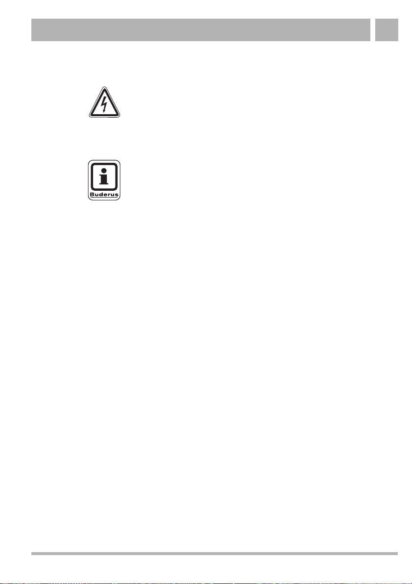
Fig. 1 xM10 function module (in this case wall-mounted)
Item 1: Terminal cover
Item 2: Fuse holder
Item 3: Function module
Item 4: Identification plate and access to the spare fuse and to the rotary
encoder (for MM10 only)
Item 5: Operation/fault LED
Item 6: Wall bracket
4
5
6
PLEASE NOTE
If you are installing the MM10 function module you should ensure
that behind the identification plate (Fig. 1, Item 5) the rotary
encoder is set to position 2 (corresponding to heating circuit 2).
We reserve the right to make any changes due to technical modifications.
6
Installation instructions xM10 function modules • Issue 03/2003
Buderus Heiztechnik GmbH • http://www.heiztechnik.buderus.de
Page 7
Wall-mounted boilers 3
3 Wall-mounted boilers
This chapter describes installation of the xM10 function modules in
a wall-hanging boiler (in this example Logamax plus GB142).
At most, two function modules can be integrated in a wall-mounted
boiler.
2
1
3
4
Fig. 2 Hook the function module into position, ensuring that it is
Item 1: Function module in slot 1
Item 2: Function module in slot 2
Item 3: Lock
Item 4: Function module
engaged
! Remove casing from the boiler (see the installation and
maintenance instructions).
! Fit the function module (Fig. 2, Item 4) in the recesses using
the locking hooks and get it to engage on the lock (Fig. 2,
Item 3.
We reserve the right to make any changes due to technical modifications.
Buderus Heiztechnik GmbH • http://www.heiztechnik.buderus.de
Installation instructions xM10 function modules • Issue 03/2003
7
Page 8

Wall-mounted boilers3
WARNING!
Making electrical connections
RISK TO LIFE
from electric shock.
! Isolate the heating system from the mains supply using the
emergency stop switch or by extracting the mains fuse.
5
4
Fig. 3 Providing an electrical supply
Item 1: Terminal box for boiler
Item 2: Mains supply cable (in cable harness)
Item 3: Terminals for 230-V inputs or outputs (e. g. for mains connection
Item 4: Low-voltage terminals (e. g. for bus system or temperature
Item 5: Bus cable (in cable harness)
We reserve the right to make any changes due to technical modifications.
8
or pumps)
sensors)
Installation instructions xM10 function modules • Issue 03/2003
2
1
3
Buderus Heiztechnik GmbH • http://www.heiztechnik.buderus.de
Page 9

Wall-mounted boilers 3
Using the terminals provided, connect the mains supply cable, bus
cable and other components (e. g. pumps, temperature sensors
etc.) to the function module according to the application. The exact
assignment (components - terminals) is shown in the connection
diagrams supplied with the equipment.
! Remove cover from terminal box (Fig. 3, Item 1).
! Carefully take the mains supply cable (Fig. 3, Item 2) and bus
cable (Fig. 3, Item 5) from the boiler's cable harness and
connect them to terminals (Fig. 3, Item 3 and 4) of the function
module.
! Carefully connect other components to terminals (Fig. 3,
Item 3 and 4) on the function module in accordance with the
connection diagram.
If you install a second function module you must bridge the mains
supply cable and bus cable from the first to the second function
module using the cables provided.
PLEASE NOTE
You should ensure that the mains connection is implemented
correctly in respect of phases to ensure that the system is properly
protected by the fuse.
We reserve the right to make any changes due to technical modifications.
Buderus Heiztechnik GmbH • http://www.heiztechnik.buderus.de
Installation instructions xM10 function modules • Issue 03/2003
9
Page 10

Wall-mounted boilers3
3
2
1
Fig. 4 Close terminal cover
Item 1: Terminal box cover
Item 2: Terminal cover on function module
Item 3: Cross-head screw with square head
! Replace cover on terminal box (Fig. 4, Item 1).
! Replace terminal cover on function module (Fig. 4, Item 2).
! Tighten the cross-head screws (Fig. 4, Item 3) either with a
cross-head screwdriver or with a bleed key.
! Close the boiler casing.
We reserve the right to make any changes due to technical modifications.
10
Installation instructions xM10 function modules • Issue 03/2003
Buderus Heiztechnik GmbH • http://www.heiztechnik.buderus.de
Page 11

Wall-mounted boilers 3
! Commission the heating system and controller.
PLEASE NOTE
Connected pumps can some times start immediately after the
system is switched on unless the controller has detected the
function module. The heating system must be filled up to ensure
that the pumps cannot run dry.
PLEASE NOTE
A higher-level control unit must be installed to ensure problemfree operation of the function modules.
! When commissioning the system you should carry out all the
required settings with the help of the service instructions
provided.
! You should also check that the system conditions are set
correctly in the control unit.
We reserve the right to make any changes due to technical modifications.
Buderus Heiztechnik GmbH • http://www.heiztechnik.buderus.de
Installation instructions xM10 function modules • Issue 03/2003
11
Page 12

Floor-standing boilers4
4 Floor-standing boilers
This chapter describes installation of the xM10 function modules in
the Logamatic MC10 controller in floor-standing boilers.
At most, two function modules can be integrated in a floor-standing
boiler.
Fig. 5 Remove the cover
! Undo the 2 screws on the top of the cover (Fig. 5).
! Remove the cover by pulling it upwards in the direction
indicated by the arrow.
We reserve the right to make any changes due to technical modifications.
12
Installation instructions xM10 function modules • Issue 03/2003
Buderus Heiztechnik GmbH • http://www.heiztechnik.buderus.de
Page 13

Floor-standing boilers 4
1
2
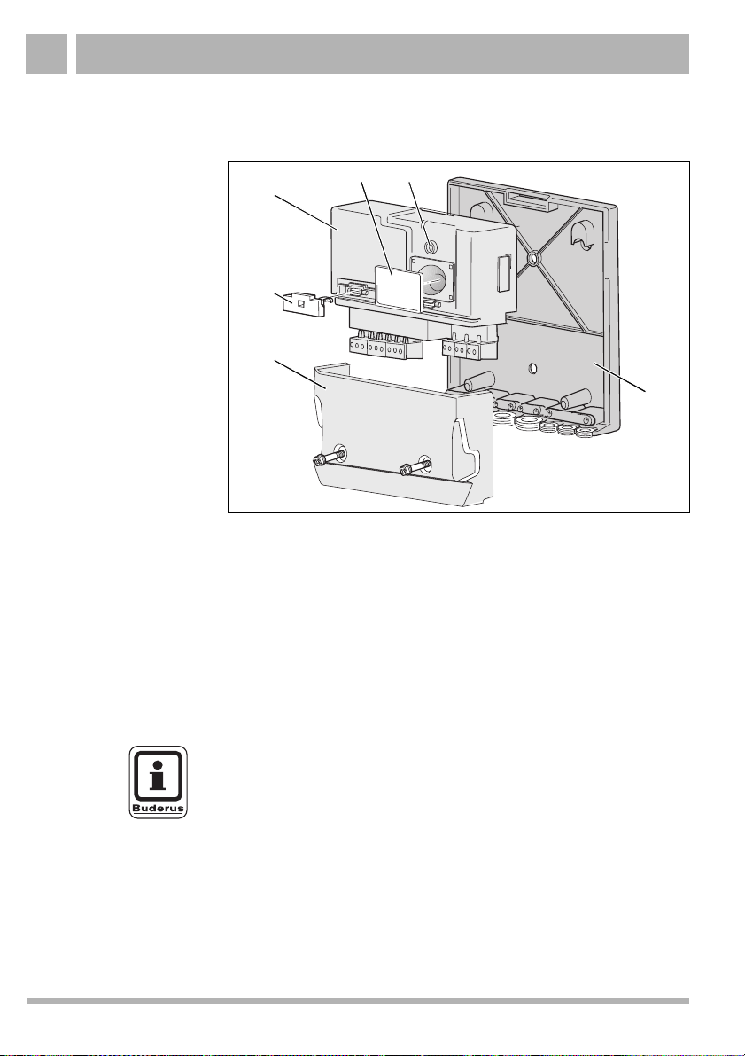
Fig. 6 Install the function module, ensuring that it is engaged
Item 1: Function module in slot 1
Item 2: Function module in slot 2 (if required)
! Present the outside hooks on the rear of the function module to
the tabs on the controller.
! Press the front side of the module downwards.
Making electrical connections
RISK TO LIFE
from electric shock.
WARNING!
We reserve the right to make any changes due to technical modifications.
! Isolate the heating system from the mains supply using the
emergency stop switch or by extracting the mains fuse.
Buderus Heiztechnik GmbH • http://www.heiztechnik.buderus.de
Installation instructions xM10 function modules • Issue 03/2003
13
Page 14

Floor-standing boilers4
3
4
2
1
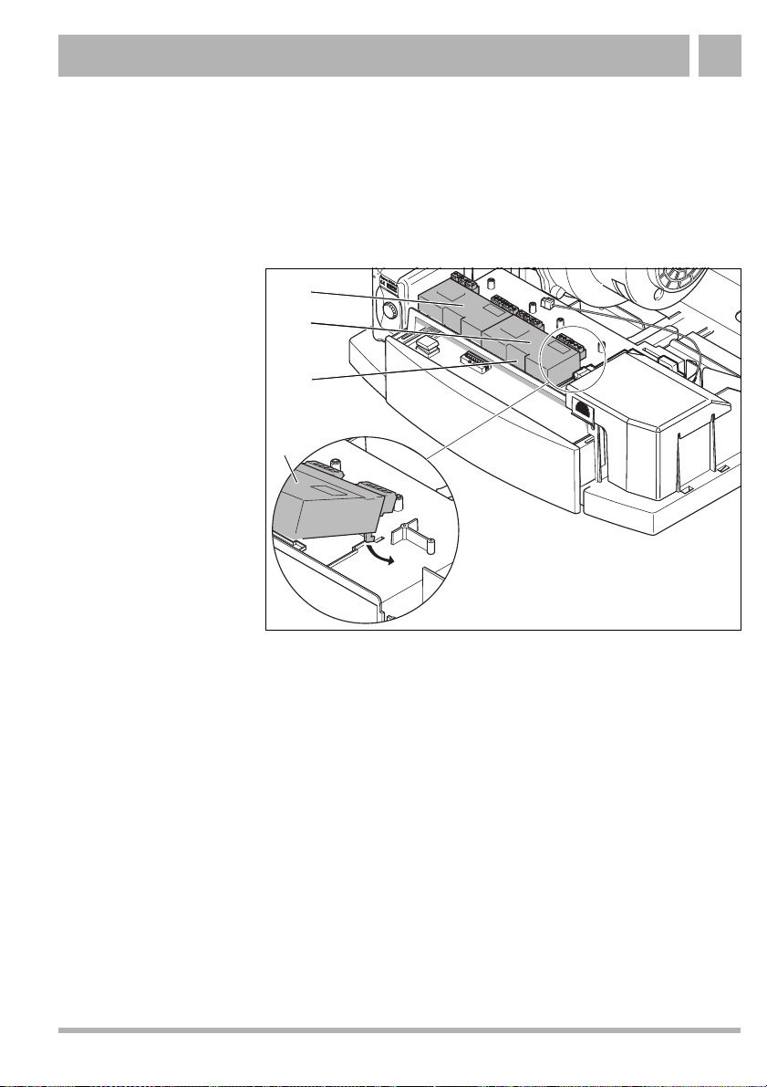
Fig. 7 Provide an electrical supply for the first function module
Item 1: Mains supply cable
Item 2: Bus cable
Item 3: Terminals for 230 V inputs or outputs (e. g. for mains connection
Item 4: Low-voltage terminals (e. g. for bus system or temperature
or pumps)
sensors)
Using the terminals provided, connect the mains supply cable, bus
cable and other components (e. g. pumps, temperature sensors
etc.) to the function module according to the application. The exact
assignment (components - terminals) is shown in the connection
diagrams supplied with the equipment.
! Carefully take the mains supply cable and bus cable (Fig. 7,
Item 1 and 2) from the boiler's controller and connect them to
terminals (Fig. 7, Item 3 and 4) on the first function module.
! Carefully connect other components to terminals (Fig. 7,
Item 3 and 4) on the function module in accordance with the
connection diagram.
We reserve the right to make any changes due to technical modifications.
14
Installation instructions xM10 function modules • Issue 03/2003
Buderus Heiztechnik GmbH • http://www.heiztechnik.buderus.de
Page 15

Floor-standing boilers 4
1
2
Fig. 8 Provide an electrical supply for the second function module
Item 1: Mains supply cable
Item 2: Bus cable
If you install a second function module you must bridge the mains
supply cable and bus cable from the first to the second function
module using the cables provided.
Using the terminals provided, connect the mains supply cable, bus
cable and other components (e. g. pumps, temperature sensors
etc.) to the function module according to the application. The exact
assignment (components - terminals) is shown in the connection
diagrams supplied with the equipment.
! Carefully connect the mains supply cable and bus cable
(Fig. 7, Item 1 and 2) from the first function module to the
terminals on the second function module.
! Carefully connect other components to the terminals on the
function module in accordance with the connection diagram.
We reserve the right to make any changes due to technical modifications.
Buderus Heiztechnik GmbH • http://www.heiztechnik.buderus.de
Installation instructions xM10 function modules • Issue 03/2003
15
Page 16

Floor-standing boilers4
! Commission the heating system and controller.
PLEASE NOTE
Connected pumps can some times start immediately after the
system is switched on unless the controller has detected the
function module. The heating system must be filled up to ensure
that the pumps cannot run dry.
PLEASE NOTE
A higher-level control unit must be installed to ensure problemfree operation of the function modules.
! When commissioning the system you should carry out all the
required settings with the help of the service instructions
provided.
! You should also check that the system conditions are set
correctly in the control unit.
We reserve the right to make any changes due to technical modifications.
16
Installation instructions xM10 function modules • Issue 03/2003
Buderus Heiztechnik GmbH • http://www.heiztechnik.buderus.de
Page 17

Wall mounting 5
5 Wall mounting
This chapter describes the wall mounting of xM10 function
modules.
2
2
5 mm
1
3
Fig. 9 Install wall bracket
Item 1: xM10 wall bracket
Item 2: Screws (4 × 45)
Item 3: Hole for more secure attachment
! Mark hole positions for the wall bracket (Fig. 9, Item 1).
! Drill holes according to the wall bracket's drilling template
(Fig. 9, Item 1) (Ø 6 mm).
! Insert wall plugs in the holes and screw in the screws provided
(Fig. 9, Item 2) until their heads are 5 mm proud of the wall.
We reserve the right to make any changes due to technical modifications.
Installation instructions xM10 function modules • Issue 03/2003
Buderus Heiztechnik GmbH • http://www.heiztechnik.buderus.de
17
Page 18

Wall mounting5
! Hook the wall bracket into position (Fig. 9, Item 1) and tighten
screws. If necessary, secure the bracket (Fig. 9, Item 1) to the
wall using its extra hole (Fig. 9, Item 3).
21
Fig. 10 Install the function module, ensuring that it is engaged
Item 1: Function module
Item 2: Lock
! First fit the bottom of the function module (Fig. 10, Item 1 in the
wall holder and get it to engage on the lock (Fig. 10, Item 2).
We reserve the right to make any changes due to technical modifications.
18
Installation instructions xM10 function modules • Issue 03/2003
Buderus Heiztechnik GmbH • http://www.heiztechnik.buderus.de
Page 19

Wall mounting 5
Make electrical connections
RISK TO LIFE
from electric shock.
WARNING!
! Isolate the heating system from the mains supply using the
emergency stop switch or by removing the mains fuse.
4
3
2
1
Fig. 11 Provide an electrical supply
Item 1: Mains supply cable
Item 2: Rubber sleeve (e. g. for mains connection)
Item 3: Strain relief (e. g. for mains connection)
Item 4: Terminals for 230 V inputs or outputs (e. g. for mains connection
Item 5: Low-voltage terminals (e. g. for bus system or temperature
Item 6: Bus cable
We reserve the right to make any changes due to technical modifications.
Installation instructions xM10 function modules • Issue 03/2003
or pumps)
sensors)
Buderus Heiztechnik GmbH • http://www.heiztechnik.buderus.de
5
6
19
Page 20

Wall mounting5
Using the terminals provided, connect the mains supply cable, bus
cable and other components (e. g. pumps, temperature sensors
etc.) to the function module according to the application.
The exact assignment (components - terminals) is shown in the
connection diagrams supplied with the equipment.
! Start by fitting the rubber sleeves (Fig. 11, Item 2) over the
cable.
! Carefully connect the mains supply cable (Fig. 11, Item 1, the
bus cable (Fig. 11, Item 6 and other components to terminals
(Fig. 11, Item 4 and 5 on the function module in accordance
with the connection diagram.
! Secure the strain relief devices (Fig. 11, Item 3) correctly using
the clips provided.
PLEASE NOTE
You should ensure that the mains connection is implemented
correctly in respect of phases to ensure that the system is properly
protected by the fuse. A mains connection via a plug with an earth
conductor is not permissible.
We reserve the right to make any changes due to technical modifications.
20
Installation instructions xM10 function modules • Issue 03/2003
Buderus Heiztechnik GmbH • http://www.heiztechnik.buderus.de
Page 21

Wall mounting 5
3
2
1
Fig. 12 Fit terminal cover
Item 1: Bleed key and/or screwdriver
Item 2: Cross-head screw with square head
Item 3: Terminal cover
! Fit the terminal cover (Fig. 12, Item 3).
! Tighten the cross-head screw (Fig. 12, Item 2 either with a
cross-head screwdriver or with a bleed key (Fig. 12, Item 1).
We reserve the right to make any changes due to technical modifications.
Buderus Heiztechnik GmbH • http://www.heiztechnik.buderus.de
Installation instructions xM10 function modules • Issue 03/2003
21
Page 22

Wall mounting5
! Commission the heating system and controller.
PLEASE NOTE
Connected pumps can some times start immediately after the
system is switched on unless the controller has detected the
function module. The heating system must be filled up to ensure
that the pumps cannot run dry.
PLEASE NOTE
A higher-level control unit must be installed to ensure problemfree operation of the function modules.
! When commissioning the system you should carry out all the
required settings with the help of the service instructions
provided.
! You should also check that the system conditions are set
correctly in the control unit.
We reserve the right to make any changes due to technical modifications.
22
Installation instructions xM10 function modules • Issue 03/2003
Buderus Heiztechnik GmbH • http://www.heiztechnik.buderus.de
Page 23

Notes
We reserve the right to make any changes due to technical modifications.
Buderus Heiztechnik GmbH • http://www.heiztechnik.buderus.de
Installation instructions xM10 function modules • Issue 03/2003
23
 Loading...