

Page 1
Panel Radiators
Design Manual
For Buderus Panel Radiator models:
- Model 21
- Model 22
- Towel Warmers
Page 2

Panel Radiator
Design Manual
2 |
Technical specications are subject to change without prior notice
Panel Radiator Design Manual | 12.2009
Page 3

Applications manual
Panel Radiator
Design Manual
Table of Contents
1 General Info 5
2 Safety 6
3 Product Description 7
4 Mounting Guidelines 15
5 Radiator Output Ratings 17
6 Radiator Selection Procedure 21
7 Piping Arrangements 22
8 Buderus NB Style Towel Racks 32
Panel Radiator Design Manual | 12.2009 Technical specications are subject to change without prior notice
| 3
Page 4

Panel Radiator
Design Manual
4 |
Technical specications are subject to change without prior notice
Panel Radiator Design Manual | 12.2009
Page 5

Applications manual
1. General information
Panel Radiator
Design Manual
1.1. This manual
This application manual is intended for engineers,
architects, contractors, and installers. It provides
specication on panel radiator and towel rack models,
sizing information, and system layout assistance for
hydronic heating systems with panel radiators.
This manual describes the basic operation of the Buderus
panel radiators and towel racks, thermostatic controls and
piping accessories. It also provides rough in dimensions
and installation procedures.
Radiator heating capacities are listed by model, height and
length and are based on different supply water
temperatures.
For added savings Buderus recommends running panel
radiator systems at reduced temperatures. When using a
condensing boiler, the system should be designed so that
the return water temperature makes the boiler condense
except on the coldest days of the year.
Dew point ue gases:
• Natural Gas: 130°F (55°C)
• #2 Fuel Oil: 118°F (48°C)
1.2. Standards, regulations and directives
It is the responsibility of the installer to ensure that the
system corresponds to all current regulations and rules.
General guide lines are discussed with respect to sizing
and radiator selection. The design and radiator selection
process for one and two pipe heat distribution systems are
provided including examples. Quick and easy “rules of
thumb” for trouble free installation and operation are
presented.
Panel Radiator Design Manual | 12.2009 Technical specications are subject to change without prior notice
| 5
Page 6
2. Safety
Panel Radiator
Design Manual
2.1. Layout of the instructions
Two levels of danger are identied and signied by the
following terms:
WARNING! RISK OF FATAL INJURY
Identies possible dangers emanating from
a product, which might cause serious injury
or death if appropriate care is not taken.
WARNING! RISK OF INJURY/SYSTEM
DAMAGE
Indicates a potentially dangerous situation
that could cause minor or moderately
serious injuries and damage to property.
Additional symbols for identication of dangers and user
instructions:
USER NOTE
User tips for optimal use of equipment and
adjustment as well as other useful information.
2.4. Disposal
● Dispose of the packaging in an environmentally
responsible manner.
— Dispose of defunct components through an
authorized agent in an environmentally
responsible manner.
2.2. Please follow these instructions
Only use original Buderus spare parts.
Damage caused by the use of parts not
supplied by Buderus is excluded from the
Buderus warranty.
2.3. Tools, materials and accessories
For the installation of panel radiators and towel racks,
you will need standard tools used for central heating,
boiler and DHW water systems.
6 |
Technical specications are subject to change without prior notice
Panel Radiator Design Manual | 12.2009
Page 7
Applications manual
Panel Radiator
Design Manual
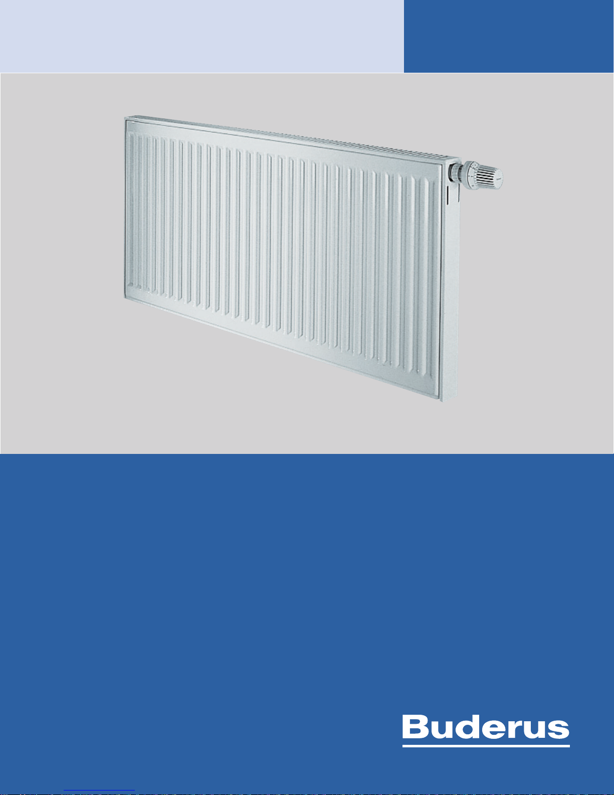
3. Product Description
With the line of panel radiators Buderus offers a real
alternative to conventional baseboard heating. For
decades Europeans have enjoyed the unsurpassed
comfort and versatility of radiant heat that is more exible,
efcient, and a cleaner alternative to baseboard heating.
Unlike conventional baseboard heat that provides only
convection heat, the high performance hydronic steel
panel radiators provide the perfect combination of both
convective and radiant heat while offering signicant
savings from lower water temperatures.
Radiant Heat vs. Convection Heat:
Forced hot air or baseboard systems with n tubes
produce heat that warms the air by convection, which
requires high water temperatures to effectively output
BTU. This results in large temperature differentials in the
room, can cause drafty conditions, and in many cases
results in hot air collecting at the ceiling and cooler air at
oor level.
Radiant heat, like the sun, warms objects rather than just
the air, creating a greater sense of warmth while requiring
lower room temperatures. The added radiant component
from panel radiators may permit return water
temperatures below 130°F (55°C) for natural gas and
118°F (48°C) for oil red appliances, allowing a
condensing boiler to condense and take advantage of its
added efciency.
Because Buderus radiators don’t turn “on and off”
randomly in the way traditional baseboards do, they are
virtually silent — eliminating the noise associated with
other heating systems.
The exibility of Buderus panel radiators offers builders,
designers, and homeowners a variety of sizes for any
heating and design requirement. These space-saving
panel radiators require between a third to a quarter of the
space of baseboard heating and are a perfect solution
where design exibility is important. The radiator’s unique
wall-mounted and optional oor-mounted styling also
minimizes areas where dust and dirt can collect and
allows for greater exibility in furniture placement.
Panel radiators from Buderus are stocked in several
heights and lengths, and in two widths.
Each panel radiator includes side panels, front and back
grill covers, and a owsetter valve. This feature enables
the system installer to quickly and easily regulate the
water ow through the radiator room by room. The result
is a consistent, even heat throughout all panel units in the
house — no more feeling warm in one room and chilly in
another.
Buderus Panel Radiators
Buderus “solidoux N” panel radiators are manufactured
from 18 Gauge (0.049”/0.125mm) steel panels. They
consist of water lled welded steel panels with convector
channels mounted on the back. These layers are
combined and arranged into two basic models:
model # 21 (width 2.5"), model # 22 (width 4.0").
Standard equipment with each radiator include wall
mounting brackets, bottom piping connections, built in
manual air vents, a drain plug and a ow setter valve with
a protective cover over it.
All stocking models have the ow setter (control) valve
and piping on the same side, and can be mounted facing
left or right.
Available Models
Model 21 Table 1
Dimensions Dry weight Water volume
H x L x W lbs kg gal liters
12"x24"x2"
12"x36"x2"
12"x48"x2"
12"x59"x2" 50 23 1.6 6.3
12"x63"x2" 54 24 1.8 6.7
12"x71"x2" 60 27 2.0 7.6
20"x24"x2" 35 16 1.0 3.8
20"x36"x2" 52 24 1.5 5.8
20"x48"x2" 69 31 2.0 7.7
20"x59"x2" 85 39 2.5 9.4
20"x63"x2" 91 41 2.6 10.1
20"x71"x2" 102 47 3.0 11.4
20 9 0.7 2.6
31 14 1.0 3.8
41 19 1.3 5.1
Special order sizes, up to 3‘ high and 10‘ long, are
available with a 4 to 6 week lead-time.
Buderus panel radiators come in a multi-layered, powder
coat enamel white nish that is durable, easy to clean
and ideal for most existing color schemes. They can also
easily be custom painted to any desired color.
Panel Radiator Design Manual | 12.2009 Technical specications are subject to change without prior notice
24"x24"x2" 41 19 1.2 4.5
24"x36"x2" 62 28 1.7 6.7
24"x48"x2" 83 38 2.3 8.9
24"x59"x2" 102 46 2.9 10.9
24"x63"x2" 108 49 3.1 11.7
24"x71"x2" 122 56 3.4 13.2
| 7
Page 8
Panel Radiator
Design Manual
Buderus Towel Warmers
Model 22 Table 2
Dimensions Dry weight Water volume
H x L x W lbs kg gal liters
12"x16"x4"
12"x24"x4"
12"x36"x4"
12"x48"x4" 48 22 1.3 5.1
12"x63"x4" 63 28 1.8 6.7
12"x71"x4" 71 32 2.0 7.6
20"x16"x4" 27 12 0.7 2.6
20"x24"x4" 41 19 1.0 3.8
20"x36"x4" 62 28 1.5 5.8
20"x48"x4" 82 37 2.0 7.7
20"x59"x4" 101 46 2.5 9.4
20"x63"x4" 108 49 2.6 10.1
20"x71"x4" 121 121 3.0 11.4
24"x16"x4" 33 15 0.8 3.0
24"x24"x4" 49 22 1.2 4.5
24"x36"x4" 74 34 1.7 6.7
24"x48"x4" 98 45 2.3 8.9
24"x59"x4" 121 55 2.9 10.9
24"x63"x4" 129 59 3.1 11.7
24"x71"x4" 146 66 3.4 13.2
16 7 0.4 1.7
24 11 0.7 2.6
36 16 1.0 3.8
Nothing is more comforting than a warm towel after a
bath or shower. European towel warmers from Buderus
are the perfect combination of contemporary styling and
economical luxury. Towel warmers are also an excellent
way to add heat and remove humidity and dampness
from any bathroom.
Available in three sizes, the NB style towel warmers are
nished in a high quality white enamel for use in damp
environments like bathrooms. They should not be
installed in showers or areas where they are exposed to
direct water spraying.
The NB style is perfect for minimal space requirements
with a total depth of 5“ and a width of 24“. It is available in
heights of 32“, 48“ and 72“. These ready-to install towel
warmers offer outputs from 2,000 BTU/Hr to 4,500 BTU/
Hr at an average water temperature of 176ºF (80ºC).
All Buderus towel warmers have the water connections
on the bottom and a manual air vent at the top. Mounting
hardware is included. Piping accessories, valves and
thermostatic heads are available as accessories.
Buderus towel warmers must not be used with
potable water or open loop systems.
Chapter 5 has detailed radiator output ratings in table and
graphical form.
36"x16"x4" 48 22 1.1 4.2
8 |
Technical specications are subject to change without prior notice
Panel Radiator Design Manual | 12.2009
Page 9
Applications manual
Panel Radiator
Design Manual
Radiator Accessories
Buderus offers a variety of accessories for installation
and control of the radiators for different piping
arrangements.
Mounting Brackets
Buderus panel radiators include wall mounting brackets.
Floor mounting brackets are available as an accessory.
Rough in instructions and mounting guidelines are
presented in chapter 5.
Piping Connections
Each stocking radiator has 20 mm (approx. 3/4) metric
male tappings on the bottom on one side. The radiator
can be mounted with these connections facing left or
right. Figure 9 shows supply and return connections
which cannot be reversed. Buderus supplies the following
compression ttings for most applications.
Compression ttings are available from Buderus in sets
of two (see Table 3). These ttings are normally secured
to the piping connection on the radiator. When diverter or
shutoff valves are used, the compression ttings mount
on the valve.
Compression ttings for panel radiators Table 3
Pipe size and style Part #
½" copper
12 x 2 mm (⅜" PEX)
16 x 2 mm (½" PEX)
20 x 2 mm (¾" PEX) 1016879
⅝" copper
6198924
1016870
1016874
1646851
Additional accessories are available that help with the
installation of the panel radiator as well as the application
in which it is installed.
Panel Radiator Design Manual | 12.2009 Technical specications are subject to change without prior notice
| 9
Page 10
Panel Radiator
Design Manual
Part no. 1016311
Straight Diverter Valve
w/ isolation valves for
panel radiators
Part no. 1016362
Straight Crossover
Valve w/ isolation
valves for panel
radiators
Part no. 3L602502
Pressure Bypass
Valve 3/4" male
thread for panel
radiators and towel
racks
Part no. 013G81013
Single Valve, angled
with adjustment
facing down for towel
racks; Head can be
replaced with
thermostatic head
#013G8250 or
Part no. 3L0143
Angled Return
Elbow with
isolation valve for
towel racks
Part no. 013G5002
Manual Adjuster
for panel padiators
and towel racks
Part no. 1016312
Angled Diverter
Valve w/ adjustable
bypass and isolation
valves for panel
radiators
Fig. 1 Valve/accessory dimensions in inches
1 0 |
Technical specications are subject to change without prior notice
Part no. 013G8250
Danfoss
Thermostatic Head
for panel radiators
Part no. 82911060
Drain Valve w/
hose bib for panel
radiators
Panel Radiator Design Manual | 12.2009
Page 11
Applications manual
Panel Radiator
Design Manual
Part no. 80262170
Straight Valve
w/ isolation valves
for panel radiators
Part no. 80262172
Angled Valve w/
isolation valves for
panel radiators
Part no. 82721124
Buderus Thermostatic
Head for panel
radiators and towel
racks
Part no. 013G8015
Single Valve, straight with adjustment at front for towel racks;
Head can be replaced with thermostatic head #013G8250
or #82721124
Part no. 013G8014
Single Valve, angled with adjustment at the front for towel
racks; Head can be replaced with thermostatic head
#013G8250 or #82721124
Part no. 82721180
Buderus Thermostatic
Head w/ remote
sensor for panel
radiators and towel
racks - capillary 79"
(2000 mm)
Fig. 2 Valve/accessory dimensions in inches continued
Panel Radiator Design Manual | 12.2009 Technical specications are subject to change without prior notice
| 11
Page 12

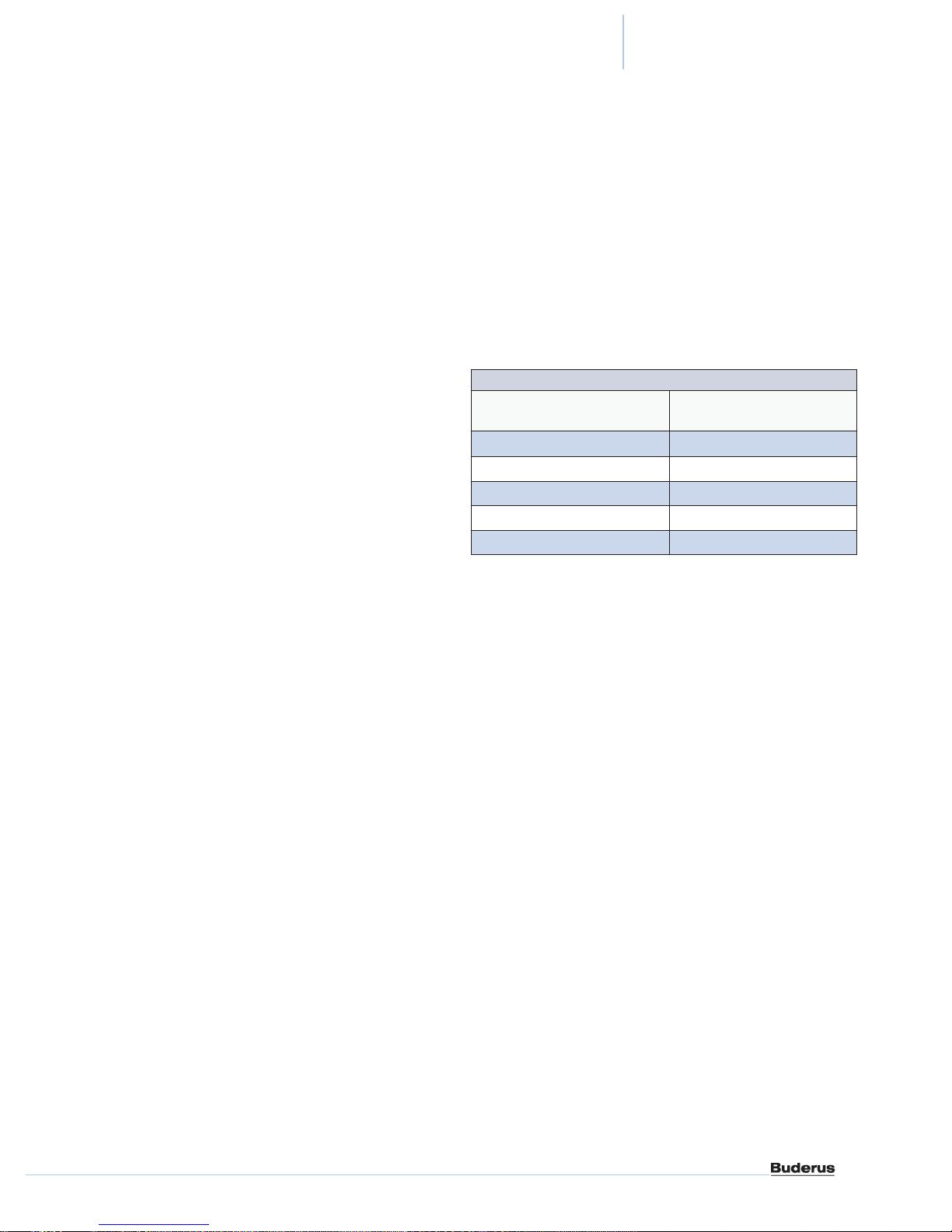
Floor Brackets for panel radiators Table 4
Floor Brackets Part Number
Model numbers: 22 817-BUD
Model numbers: 21 817-BUD-1
Optional covers for brackets 81606400
Flow Setter Valve:
Each radiator is equipped with a ow setter valve
mounted on the same side as the water connections of
the panel radiator. This valve consists of two part integral
components for temperature control and ow balancing.
Flow Balancing:
Panel Radiator
Design Manual
Fig. 3 Flow setter valve adjustment
Flow balancing is done by adjustment of the ring marked
1-7 and N on the ow setter valve, lining the desired
setting up with the dimple in the rst ring. Turning of the
ring adjusts the diameter available for water ow. The N
marking indicates a fully open setting; the 1 marking
indicates nearly full restriction. The diagram on page 13
shows the pressure drop across the radiator as a function
of the ow rate and setting of the ow setter.
Air Vent and Drain Plug
Each radiator is equipped with a manual air vent (1/2”)
and removable drain plug (3/4”) for draining the radiator.
A at head screw driver is needed to open the air vent.
1 2 |
Technical specications are subject to change without prior notice
Panel Radiator Design Manual | 12.2009
Page 13

Applications manual
Panel Radiator
Design Manual
Diverter Valves:
Straight (part number 1016311) and angled (part number
1016312) diverter valves are available from Buderus for
use in a one-pipe system (g. 4). Shut offs are located on
the supply and return branches to the radiator, allowing to
isolate the radiator from the piping system so it can be
drained and removed without decommissioning the
complete heating system.
Each diverter valve is factory set for 35 % ow through
the radiator and 65% through the bypass. Other ow
percentages are easily set according to the diagram (g.
5). To adjust the bypass, turn the spindle clockwise to the
fully closed position. Then open the bypass spindle the
desired number of turns from the fully closed position.
Refer to the chart that is on page 30, explaining the
pressure drop for a one-pipe system with diverter valves.
You will need to add up the pressure drop of radiator and
diverter valve when sizing the circulator.
Straight Valve
50
ADJUSTABLE
BYPASS
TO RADIATOR
TO RADIATOR
FROM RADIATOR
ISOLATION
VALVES
FROM RADIATOR
45
40
35
30
Radiator percentage of flow
50
45
40
35
30
Radiator percentage of flow
¾
Fig. 5 Setting for Straight and Angled diverter valves
1
Number of turns
Angle Valve
1¼ 1½ 1¾
1
Number of turns
2 3
Factory setting
Factory setting
ADJUSTABLE
BYPASS
ISOLATION
VALVES
Fig. 4 Straight and Angled Diverter Valves
Installation considerations:
1. The valve mounts directly to the supply and return
of the radiator. The compression ttings now
connect to the diverter valve.
2. Allow 5” oor clearance below the radiator for the
straight; 4” for the angled diverter valve.
Panel Radiator Design Manual | 12.2009 Technical specications are subject to change without prior notice
| 13
Page 14

Thermostatic Sensor head:
Adding a Buderus Thermostatic Head enables room-byroom zone control for optimum comfort and efciency. It
is easily installed on the ow setter valve.
A thermostatic head with remote sensor is available for
locations where the valve head would be covered behind
a curtain or otherwise blocked from sensing the actual
room temperature. Length of the capillary: 79“ (2000
mm).
Panel Radiator
Design Manual
4
3
Buderus
2
Buderus
Temperature Control:
Thermostatic control head is mounted on the ow setter
valve of panel radiators and towel racks, and through its
capillary expansion controls the ow rate and therefore
the heat output of the panel. When using the thermostatic
head the ow setter valve needs to be in the N position. A
moveable, spring-loaded seat assembly inside the ow
setter valve regulates the water ow through thermostatic
action of the control head. This thermostatic head is
required for individual temperature control at each
radiator. The asterics provides frost protection of the
panel itself provided the heating system is operational.
The sensor indicator numbers correspond to the following
approximate temperatures:
Thermostatic Sensor Head Setting Table 5
Dial * 1 2 3 4 5
Room Temperature °F 40 57 63 68 73 79
Room Temperature °C 5 14 17 20 23 26
1
Fig. 6 Thermostatic Sensor Head
1 4 |
Technical specications are subject to change without prior notice
Panel Radiator Design Manual | 12.2009
Page 15

Applications manual
4. Mounting Guidelines
Panel Radiator
Design Manual
Panel Radiator Installation
Both model 21 and 22 radiators can be wall or oor
mounted. All wall brackets must be secured to studs or
other supports of sufcient strength for panel radiator
weight. Radiators with a length of 71" or less require 2
brackets (1 set); lengths 79” or larger require 2 sets.
Note: Do not attempt to mount radiators soley to sheet
rock or similar material.
Radiator Clearance Requirements:
Clearance for right hand radiators Table 6
Clearance
dimensions
Floor 2" (51mm)
Minimum
clearance
4" (102mm)
5" (127mm)
5" (127mm)
Reason
- No diverter valves
- Angled diverters
- Straight diverters
- Cross-over valves
Model 21 and 22: Wall Mounting
Each bracket is supplied with a slotted plastic locating
clip. Position brackets evenly along the radiator and at
least 4" in from either side for aesthetic reasons. The
bottom of the radiator rests 5/8" above the bottom edge
of the bracket. The radiator wall clearance can be set at
1-9/16" or 2-1/16" depending on the orientation of the
plastic locating clips. Piping connections are located at
1-3/16" return and 3-3/16” (supply) in from the valve side
of the radiator. The piping wall offset is 3-9/16" or 4-1/16"
for both Model 21 and 22 radiators. For left hand
radiators, measure these dimensions from the left side.
See Fig. 8 and 9 for details.
Mount the brackets to studs or other wall supports
capable of carrying the load of the full radiator (see
Tables 1 & 2). Use at least 2 screws per bracket. Pull the
T-shaped plastic securing plate forward and slide the top
holder upward.
Insert the radiator with the bottom edge into the locating
clip at the bottom of the bracket. Now slide the top
bracket down to secure the radiator in place. Refer to the
installation instructions included with the brackets for
details.
Side of
owsetter
valve
Side opposing
the owsetter
valve
Top 2" - 4"
2" - 4"
(51-102mm)
(51-102mm)
5" (127mm) Thermostatic Sensor Head
Access to manual air
bleeder
Access to the top of wall
bracket
Model 21 and 22: Floor Mounting
Floor brackets permit placement of Model 21 and 22
radiators in front of tall windows or where wall mounting
is not an option. These brackets include a oor pedestal
mount, radiator support, channel section and tightening
assembly. The top grille of the radiator must be removed
to install the channel section and tightening assembly.
Radiators are adjustable in height from 4” to 8” bottom
clearance.
Fig. 7 Floor mounting bracket
Panel Radiator Design Manual | 12.2009 Technical specications are subject to change without prior notice
| 15
Page 16

Panel Radiator
Design Manual
Finished wall
2½"
Minimum of
4"
Bracket
1⁹/₁₆"
or
2¹/₁₆"
Panel Radiator
Bracket
TOP VIEW
Fig. 8 Model 21 Panel Radiator Rough in Dimensions in inches for wall mounting
Finished wall
Supply
Stud
Minimum of
4"
Return
2" 1³/16"
Stud
2⅝" from
finished
wall to
center of
tapings
1 2
Minimum of
4"
Bracket
4"
1⁹/₁₆"
or
2¹/₁₆"
Panel Radiator
Bracket
TOP VIEW
Fig. 9 Model 22 Panel Radiator Rough in Dimensions in inches for wall mounting
Supply
Minimum
of 4"
Return
2"
1³/
3⅜" from
finished
wall to
center of
tapings
1 2
16"
1 6 |
Technical specications are subject to change without prior notice
Panel Radiator Design Manual | 12.2009
Page 17

Applications manual
5. Radiator Output Ratings
Outputs depend on panel radiator size, average water
temperature, and room temperature.
Four examples are presented below to illustrate a range
of options. If none of them applies, use Figure 10 and
Table 9 to determine output based on individual
requirements.
Tables 7 and 8 show the outputs of Model 21 and 22
in-stock radiators at four different water temperatures.
Use the high temperature column if restricted in wall
space. To maximize efciency in condensing boiler
applications, ensure the return water temperature drops
below the ue gas’ dew point of 131°F (55°C) for
signicant periods of the heating season.
2½
Radiator outputs in BTU/Hr:
Panel Radiator
Design Manual
Model 21: 2½" (63.5mm) deep Table 7
Output BTU/hr
Supply 194°F (90°C) 176°F (80°C) 158°F (70°C) 140°F (60°C) Part Number
Delta T 36°F (20°C) 36°F (20°C) 18°F (10°C) 18°F (10°C)
12"x24"x2½"
12"x36"x2½"
12"x48"x2½"
12"x59"x2½" 4700 3700 3200 2300 3-41259
12"x71"x2½" 5700 4500 4000 2900 3-41271
20"x24"x2½" 2800 2200 1900 1400 3-42024
20"x36"x2½" 4200 3300 2900 2100 3-42036
20"x48"x2½" 5600 4400 3900 2800 3-42048
20"x59"x2½" 7000 5500 4800 3500 3-42059
20"x71"x2½" 8400 6600 5800 4200 3-42071
24"x24"x2½" 3200 2500 2200 1600 3-42424
24"x36"x2½" 4900 3800 3400 2400 3-42436
24"x48"x2½" 6500 5100 4500 3200 3-42448
24"x59"x2½" 8100 6300 5600 4000 3-42459
24"x63"x2½" 8700 6800 6000 4300
24"x71"x2½" 9700 7600 6700 4800 3-42471
1900 1500 1300 1000 3-41224
2900 2300 2000 1400 3-41236
3800 3000 2600 1900 3-41248
All values based on 68°F (20°C) room temperature.
Panel Radiator Design Manual | 12.2009 Technical specications are subject to change without prior notice
| 17
Page 18

Panel Radiator
Design Manual
Model 22: 4" (100mm) deep Table 8
Output BTU/hr
Supply 194°F (90°C) 176°F (80°C) 158°F (70°C) 140°F (60°C) Part Number
Delta T 36°F (20°C) 36°F (20°C) 18°F (10°C) 18°F (10°C)
12"x16"x4"
12"x24"x4"
12"x36"x4"
12"x48"x4" 4900 3800 3400 2400 3-21248
12"x63"x4" 6500 5100 4500 3300 3-21263
12"x71"x4" 7300 5800 5100 3700 3-21271
20"x16"x4" 2500 2000 1700 1200 3-22016
20"x24"x4" 3700 2900 2600 1900 3-22024
20"x36"x4" 5600 4400 3900 2800 3-22036
20"x48"x4" 7500 5900 5200 3700 3-22048
20"x59"x4" 9300 7300 6400 4600 3-22059
20"x71"x4" 11200 8800 7800 5600 3-22071
24"x16"x4" 2900 2300 2000 1400 3-22416
24"x24"x4" 4300 3400 3000 2200 3-22424
24"x36"x4" 6500 5100 4500 3200 3-22436
24"x48"x4" 8700 6800 6000 4300 3-22448
24"x59"x4" 10800 8400 7400 5300 3-22459
24"x71"x4" 13000 10200 9000 6500 3-22471
36"x16"x4" 3500 2700 2400 1700 3-23616
1600 1300 1100 800 3-21216
2400 1900 1700 1200 3-21224
3700 2900 2500 1800 3-21236
All values based on 68°F (20°C) room temperature.
1 8 |
Technical specications are subject to change without prior notice
Panel Radiator Design Manual | 12.2009
Page 19

Applications manual
If tables 7 and 8 do not match a system‘s requirements,
the following guidelines provide means to calculate the
effects of ambient room temperature, supply water
temperature and temperature drop through the radiator
on the radiator output.
Ambient room temperature effect: The (adjusted)
output of a radiator at any room temperature (∆T room)
can be computed from the output listed at a room
temperature of 68°F (20°C) as:
Adjusted Output = Listed Output x [1+α x (68-Troom)]
(Troom in °F) where α is a correction factor computed as:
α = 1.385 / (ΔT supply - 75) with ΔT supply in °F.
Note: The listed radiator output depends on the supply
temperature.
Example: Select the proper radiator to heat a porch
which is to be kept at 55°F (13°C) during the winter.
Maximum heat loss is 8,750 Btu/hr. Assume supply
temperature equal to 194°F (90°C).
Panel Radiator
Design Manual
Solution: The larger temperature difference between the
radiator and the porch increases the radiator output. To
nd the proper size radiator, we must compute the listed
output at 68°F (20°C).
Adjusted Output = 8,750 Btu/hr at 194°F (90°C) and 55°F
(13°C). (∆T room).
Compute correction factor α as:
α = 1.385 / (194 - 75) = 0.0116
Listed Output = 8,750 / [1 + (0.0116 x (68 - 55)] =
7,560 Btu/hr
From Table 8: Use Model 22 20” x 48” x 4“ instead of
Model 22 24” x 48” x 4“ (listed output = 7,500 Btu/hr).
This ambient room temperature effect is generally small
and need only be considered in system design if desired
room temperatures are well beyond the typical 68 - 72°F
(20 - 22°C) range.
Supply water temperature effect: The effect of different
supply temperatures on the output of panel radiators is
computed using the conversion factors of Table 9 or read
directly from the Performance Curves in Figure 10.
Table 9 contains conversion factors needed to compute
the adjusted radiator output from the listed ratings. The
∆T factor is computed as the difference between the
average water temperature and room temperature.
Fig. 10 Performance Curves Model 22 Radiators
Conversion Factors Table 9
∆ T in ºF (°C) Conversion Factor
10 (6) 0.045
20 (11) 0.112
30 (17) 0.198
40 (22) 0.275
50 (28) 0.367
60 (33) 0.466
70 (39) 0.569
80 (44) 0.677
90 (50) 0.789
100 (56) 0.905
108 (60) 1.000
110 (61) 1.024
120 (67) 1.147
130 (72) 1.272
140 (78) 1.401
150 (83) 1.535
Panel Radiator Design Manual | 12.2009 Technical specications are subject to change without prior notice
| 19
Page 20

Example: Compute the output of a Model 21 20” x 59”
radiator with an average water temperature of 140°F
(60°C) in the radiator and a room temperature of 70°F
(21°C).
Solution: Listed output = 7,000 Btu/hr (See Table 9)
∆T = 140 - 70 = 70°F: Conversion Factor = 0.569 (See
Table 9) Adjusted output = 0.569 x 7,000 = 3,983 Btu/hr.
Comment: The effect of the ambient room temperature is
already accounted for in the conversion factors listed in
Table 9. Figure 10 contains the performance curves for
Model 22 radiators showing the output per linear foot of
radiation for the different heights as a function of supply
temperature.
Different curves are shown based on a 18°F (10°C) and
36°F (20°C) temperature drop through the radiator and a
68°F (20°C) room temperature.
Example: A room requires 12,000 Btu/hr with 6 ft of
available space. Maximum supply temperature is 170°F
(77°C). What model(s) can be used for this application?
Panel Radiator
Design Manual
Solution: Required heat output per foot = 12,000/6 =
2,000 Btu/hr per linear foot. Check Figure 10 at 170°F
(77°C) supply temperature and 2,000 Btu/hr Output:
Model 22: Use 24” high with about 18°F (10°C) ∆T drop.
2 0 |
Technical specications are subject to change without prior notice
Panel Radiator Design Manual | 12.2009
Page 21

Applications manual
6. Radiator Selection Procedure
Several factors must be considered in the selection of a
panel radiator. These are:
• Heat loss of the room.
• Location of the radiator(s) and available oor to
window height.
• Desired piping arrangement.
• Room usage.
• Type of room control used.
All factors are discussed below and must be given
consideration prior to nal radiator size and model
selection.
1. The panel radiator(s) must have at least the required
capacity to match the heat loss. Oversizing is not a
problem provided thermostatic sensor heads or other
temperature sensitive controls are used to cycle the heat
off once the desired room temperature is reached.
Panel Radiator
Design Manual
2. Radiators are frequently selected based on the
intended location. A 3’ radiator ts nicely under a 36”
window, whereas a 24” radiator may only be needed
based on the heat loss. Window size and number of
windows as well as overall room size affect the selection
process. Once a room exceeds 12’ x 12’, it is advisable to
install 2 smaller radiators on outside walls for more
comfort.
3. The selected piping arrangement affects the radiator
sizing on monoow or one-pipe diverter valve based
systems, because the supply temperature reduces with
distance from the boiler. Minor oversizing of the last
radiators in the one-pipe system may be necessary.
4. For rooms that are used occasionally where a rapid
heat-up is required, it is advisable to install some extra
radiation. This becomes important on heating systems
operating with outdoor reset control. There is no need for
over sizing radiation in main living areas as they are
generally maintained at uniform temperatures.
5. Radiators equipped with thermostatic sensor heads on
a constant circulation system maintain a more uniform
room temperature and respond faster to temperature
disturbances such as open doors or windows, solar or
internal heat gain from appliances, lights, etc. compared
to a centrally located thermostat system.
Panel Radiator Design Manual | 12.2009 Technical specications are subject to change without prior notice
| 21
Page 22

Panel Radiator
Design Manual
7. Piping Arrangements
The design of a panel radiator based heating system
involves selection of a piping system, pipe sizes, overall
design temperature drop, required ow rates and desired
type of system control. For trouble-free system operation,
do not exceed the ow rates in Table 10.
Maximum ow rates & heat carrying capacities Table 10
Pipe size* Max
½" copper
or PEX
⅝" PEX 2.0 20,000 30,000 40,000
¾" copper 4.0 40,000 60,000 80,000
1" copper 8.0 80,000 120,000 160,000
1¼" copper 14.0 140,000 210,000 280,000
Diverter
valve
Radiator
Flow
ow
(gpm)
1.5 15,000 22,500 30,000
2.0 20,000 30,000 40,000
2.5 25,000 37,500 50,000
Note: Q (∆T = 20°F (11°C)) denotes the maximum heat
load carrying capacity based on a 20°F (11°C)
temperature drop.
*Pipe size used for main supply/return piping in multiple
one-pipe diverter valve based systems or for one-pipe
systems using monoow tees. This information is useful
for pipe sizing in two-pipe distribution systems.
This chapter discusses several piping arrangements,
guidelines for system design, pipe size, pump selection
and ne-tuning of individual components. Heat loss (Q),
water ow rate (GPM) and temperature drop (∆T) through
a hydronic heating system are related to each other as:
Q = 500 x GPM x ∆T
This equation is used extensively for accurate sizing of
radiators.
Q
(∆T=20ºF)Q(∆T=30ºF)Q(∆T=40ºF)
One-Pipe System Options
Figure 11 presents three different one-pipe
arrangements. In any one-pipe system, a single pipe
connects all radiators together. Fewer materials are
needed in a one-pipe system where a perimeter loop
supplies water to all radiators. Since water may ow
through all radiators and cools off along the way, it is
necessary to oversize the last radiator(s) in the loop. A
sizing procedure is outlined.
Table 10 shows maximum Btu load on a one-pipe system
based on pipe size and overall temperature drop.
Series loop system
All water ows through all radiators.
A thermostatic head cannot be used on any radiator as it
will shut off all ow. A central thermostat is required for
temperature control. Do not exceed heat loads as listed
in Table 10.
Option 1: one-pipe system with monoow tees
(Fig 11).
Monoow tees are used to divert some water from the
main loop into each radiator. Use one monoow tee on
the return if the radiator(s) are located above the main
loop; use two monoow tees if the radiators are installed
below the main loop. Place the tees in the main loop to
each radiator at least 12” apart. Thermostatic heads on
each radiator provide very easy means for individual
temperature control. The system can be operated off a
central thermostat or with constant circulation using an
outdoor reset system. Size the main loop based on the
selected temperature drop (20°F, 30°F, or 40°F (11°C,
17°C, 22°C)) and heat load. Make sure to oversize the
last radiators properly, especially when using an overall
temperature drop of 30°F (17°C) or 40°F (22°C). It is
important to size the main supply and return pipes for the
total heat load and volume to avoid ow restriction or
noise.
Option 2: one-pipe system with diverter valves
(Fig 12).
This arrangement is similar to using monoow tees
except that now each radiator is equipped with a diverter
valve. Secondly, the total loop ow can NOT exceed 2
GPM because of possible noise at greater ow rates. The
bypass adjustment in the diverter valve can be used to
throttle down the ow through the rst radiators and
increase ow through the last radiators in the loop to
make up for the drop in loop temperature. Thermostatic
heads on each radiator provide an easy means for
individual temperature control. The system
can operate off a central thermostat or with constant
circulation using an outdoor reset system. Follow Table
10 for pipe sizing. It is important to size the main supply
and return pipes for the total heat load and volume to
avoid ow restriction or noise.
2 2 |
Technical specications are subject to change without prior notice
Panel Radiator Design Manual | 12.2009
Page 23

Applications manual
Option 3: Multiple one-pipe systems.
Options 2 and 3 above can be installed in a multiple loop
fashion where several one-pipe systems are connected
between a common supply and return manifold. Assure
adequate ow in all piping systems when using monoow
loops and/or diverter valve loops. Isolation and balancing
valves are recommended on each loop for service and
ow control.
A properly sized pump operating on constant circulation
can supply water to all loops. A single Grundfos UP15-42
or equivalent can handle up to 3 diverter valve loops; use
a Grundfos UP26-64 or equivalent for 4 to 6 loops. Size
the main piping for the combined ow in all branches,
Option 1: One-Pipe System with Venturi Tees or Monoflow Tees.
1 2
Panel Radiator
Design Manual
following the guidelines in Table 10. Refer to the Pressure
Drop Curves (Fig. 14 & 15) on pages 30 & 31 for
estimating the pressure drop through each radiator when
using monoow tees. Use the Pressure Drop Diagram on
page 30 for a one-pipe system with diverter valves. Use
the approximate ow rate through the radiator and ow
setter valve setting to read off the pressure drop. Size the
circulator based on total ow and overall system pressure
drop. Thermostatic heads are required in this
arrangement for individual temperature control.
Ensure all supply and return piping is sized properly to
avoid restriction and noise.
1 2
1 2
Option 2: One-Pipe System with Diverter Valves.
1 2
Option 3: Multiple One-Pipe System (Home Run).
1 2
1 2
1 2
1 2
1 2
Drawing not to scale
Fig. 11 One-Pipe System Options
Panel Radiator Design Manual | 12.2009 Technical specications are subject to change without prior notice
| 23
Page 24

Panel Radiator
Design Manual
Design procedure for One-Pipe System with
monoow tees or diverter valves
1. Select radiator hook-up sequence.
2. Determine individual heat loads.
3. Determine linear footage of wall space available for
each radiator.
4. Compute the required heat load per foot for each
room.
5. Select system temperature drop ∆T = 20, 30 or 40°F
(11°C, 17°C, 22°C) and maximum supply temperature.
6. Compute the total heat load (Q) in the loop by adding
the individual heat loads.
7. Determine loop ow rate from total heat load (Q) and
selected ∆T as: GPM (loop) = Q / 500 / ∆T
8. Compute the supply temperature for each room based
on the supply temperature and heat load of the
previous room and the total loop ow rate (GPM) as:
New Supply Temp = Previous Supply Temp - (Q room)
/ 500 / GPM
With the supply temperature computed in Step 8 and the
linear heat load in Step 4, refer to Figure 10 to nd the
required radiator size, or tables 9 and 10 for the total
individual radiator output if the any of the four examples
applies. Use the same ∆T value in reading from the
curves in Figure 10 as the selected value in Step 5. In
case more than one radiator is to be installed in a room,
size all radiators based on the above procedure.
Table 11
1 Select
room
sequence
2 Heat load
per room
3 (BTU/hr)
4 Available
wall space
(ft)
5 Minimum
Required
Heat Load
per linear
ft (BTU/ft)
6 Total
heat load
(BTU/ft)
7 Total loop
GPM GPM(loop) = Q / 500 / ΔT = ____ GPM
8 Supply
temp per
room
9 List
possible
radiator
Models
and sizes
Room 1 Room 2 Room 3 Room 4
ΔT =___ºF Supply temp(room1)
=max supply temp
= _______ ºF
Q = __________BTU/Hr
____ºF ____ºF ____ºF ____ºF
2 4 |
Technical specications are subject to change without prior notice
Panel Radiator Design Manual | 12.2009
Page 25

Applications manual
Panel Radiator
Design Manual
Example: One-Pipe System Layout
Design a one-pipe system for a second oor with
individual room temperature control:
Table 12
Description Heat Load Window
Size
Bathroom 3,000 1x3 ft wide rst
Master Bedroom 9,000 2x4 ft wide second
Bedroom 2 6,000 1x3 ft wide third
Bedroom 3 4,000 1x3 ft wide fourth
Hook-up
Sequence
Solution:
Step 1. Complete the Radiator Sizing Sheet to nd
minimum size radiator.
Step 2. Select control strategy and size piping and pump
using Table 7.
Step 3-4: See Table 13.
Step 5: Assume temperature drop (∆T) = 30°F (17°C),
maximum supply temperature = 180°F (82°C).
Results: Output/ft Radiator Models
Bedroom Supply Temp = 180°F (82°C) 1500 Btu/ft
#22 20”
M. Bedroom Supply Temp = 176°F (80°C) 1125 Btu/ft
#22 x 12
Bedroom #2 Supply Temp = 164°F (70°C) 2000 Btu/ft
#22 24”
Bedroom #3 Supply Temp = 156°F (60°C) 1333 Btu/ft
#22 24”
Use 5/8 ” PEX and diverter valves (or: 3/4” copper main
line with 3/4” x 3/4” x 1/2” monoow tees) with
thermostatic heads on all radiators for individual room
control. Place a thermostat in the bathroom or master
bedroom or run constant circulation. Use a Grundfos
UP15-42, a Taco 007, or equivalent pump with a
balancing valve to throttle the ow. Noise may otherwise
develop in the diverter valves.
Table 13
1 Select
room
sequence
2 Heat load
per room
Bathroom Master
Bedroom
3000 9000 6000 4000
Bedroom 2Bedroom
3
Step 6: Add all heat loads from row 2 and enter in Step 6.
Step 7: Compute ow rate in the one-pipe system in
GPM.
The ow rate can not exceed 2 GPM when
using diverter valves. Using a larger ∆T lowers
the GPM.
Step 8: Here we must compute the supply temperature
for each room. Start with the rst room and
compute each supply temperature step by step
as shown here.
Supply Temp (1) = 180°F (82°C)
Supply Temp (2) = 180 - 3000 / (500 x 1.47) = 176°F
(80°C)
Supply Temp (3) = 176 - 9000 / (500 x 1.47) = 164°F
(70°C)
Supply Temp (4) = 164 - 6000 / (500 x 1.47) = 156°F
(60°C)
Step 9: Now with each value computed in steps 4 and 8,
locate those values in Fig. 10. The output curve
located directly above that point identies the
minimum size radiator required. Use the 18°F
(10°C) ∆T curves if designing for a 20 to 30°F (11
to 17°C) temperature drop, use the 36°F (20°C)
∆T curves if designing for a 40°F (22°C) drop.
3 Available
wall space
(ft)
4 Minimum
required
heat
load per
linear foot
(BTU/ft)
5 Minimum
Required
Heat Load
per linear
ft (BTU/ft)
6 Total
heat load
(BTU/ft)
7 Total loop
GPM GPM = Q / 500 / ΔT = 22000 / 500 / 30 = 1.5 GPM
8 Supply
temp per
room
9 Possible
radiator
Models
and sizes
2 8 3 3
1500 1125 2000 1333
ΔT = 30ºF
Supply temperature (room1)
=max supply temperature
= 180 ºF
Q = 3000 + 9000 + 6000 + 4000 = 22000 BTU/Hr
ΔT = Q / 500 / GPM
180 176 164 156
Panel Radiator Design Manual | 12.2009 Technical specications are subject to change without prior notice
| 25
Page 26

Two-Pipe System Options
Figure 12 illustrates two common two-pipe congurations.
Option 4: Two-Pipe Direct Return System
1 2
Option 5: Two-Pipe Reverse Return System
1 2
Panel Radiator
Design Manual
1 2
1 2
1 2
1 2
Pressure Bypass Valve
Drawing not to scale
Fig. 12 Two-pipe System Options
Benets of Two-Pipe Systems:
1. Each radiator is supplied with the same
temperature water maximizing radiator output.
2. No limit to the number of radiators on a two pipe
system loop; the supply and return mains must be sized
for maximum ow. Follow the guidelines in Table 10 for
sizing the supply and return runs. Use 1/2” copper or
PEX tubing to connect radiators to main runs.
3. Individual radiator control is easily done using
thermostatic sensor heads. Use constant circulation with
outdoor reset control for optimum system performance. A
central thermostat can be used for on/off control;
however, thermostat location governs overall system
control and may override individual room control.
Requirements for Two-Pipe System:
• Two main distribution pipes are needed; one for
the supply to the radiators and a second pipe for the
return to the boiler.
• A pressure actuated bypass valve (Part No.
3L602502 for a 3/4” Danfoss valve) connected between
supply and return mains is necessary on constant
circulation systems with thermostatically controlled
radiators to prevent dead-heading the pump. This bypass
valve is not needed on thermostat controlled systems if
the radiators are not equipped with thermostatic sensor
heads.
2 6 |
Technical specications are subject to change without prior notice
Panel Radiator Design Manual | 12.2009
Page 27

Applications manual
Design Procedure for Two-Pipe System
1. Determine individual heat loads.
2. Select desired overall temperature drop of systems
(∆T); i.e. 20°F (11°C), 30°F (17°C) or 40°F (22°C).
3. Compute loop ow rate GPM from:
GPM = Q / 500 / ∆T
4. Use Figure 10 or the Conversion Factors in Table 9 to
determine output of radiator models in case of lower
supply temperatures.
5. Use the Pressure Drop Chart on pages 30-31 as a
guide to set the ow setter valve for each radiator to
ensure proper ow through each radiator. Adjust ow
setter valves as needed based on system
performance. Close down the ow setter on “hot”
radiators by dialing in a lower setting on the adjustment
ring, or adjust the ow setter to a higher setting for
“cool” radiators.
6. Size piping based on system ow rate; size circulator
based on ow rate and overall system pressure drop.
Panel Radiator
Design Manual
Table 14
1 Select
room
sequence
2 Heat load
per room
3 (BTU/hr)
4 Available
wall space
(ft)
5 Minimum
Required
Heat Load
per linear
ft (BTU/ft)
6 Total
heat load
(BTU/ft)
7 Total loop
GPM GPM(loop) = Q / (500xΔT) = ______ GPM
Room 1 Room 2 Room 3 Room 4
ΔT =___ºF Supply temp(room1) =max supply
temp= _______ ºF
Q = __________BTU/Hr
8 Supply
temp per
room
9 List
possible
radiator
Models
and sizes
____ºF ____ºF ____ºF ____ºF
Panel Radiator Design Manual | 12.2009 Technical specications are subject to change without prior notice
| 27
Page 28

Panel Radiator
Design Manual
Example 2: Two-pipe System Lay-out
Design and select a two pipe panel radiator system with
the following requirements:
Table 15
Description Heat Load Window
Size
Walk-in closet 2,000 none
Bathroom 5,000 1x2 ft wide 2,500
Bedroom 1 8,000 2x3 ft wide 1,333
Bedroom 2 10,000 2x4 ft wide 1,250
Master Bedroom 12,000 2x4 ft wide 1,500
Required
BTU/ft
Total Load: 37,000 Btu/hr
System Parameters:
Maximum Supply Temperature: 194°F (90°C)
Thermostat in master bedroom for ON/OFF control.
Solution: Two-Pipe System Lay-out
1. If sufcient space is available for radiators, select
radiators based on required heat output and desired
style. Select radiators from Tables 9 & 10 since the
system temperature is similar to those listed.
Table 16: Radiator Option Determination Chart: Two-Pipe
System
Table 16
Description
Walk-in
closet
Bathroom 5000 2,500 1x #22
Bedroom 18000 1,333 2x #22
Bedroom 210000 1,250 2x #22
Master
Bedroom
Heat
Load
2000 1 3-4
12000 1,500 2x #22
BTU/ftSelected
Models
20"x36"
12"x36"
12"x48"
20"x48"
No. and
length of
radiators
1x 3ft 6-7
2x 3ft 5-6
2x 4ft 6-7
2x 4ft 7-N
Flowsetter
valve
If the radiators must be sized for the available window
space, determine the minimum needed model radiator
based on the required Btu/ft for each room from Figure
10 with a 194°F (90°C) supply temperature. Use the
same supply temperature for each radiator in a two-pipe
system.
2. Select an overall temperature drop of 20°F (11°C).
3. Compute system ow rate as: GPM = Q / 500 / ∆T =
37000 / 500 / 20 = 3.7 GPM
4. Combine all information in tabular form as shown in
Table 2.
2 8 |
Technical specications are subject to change without prior notice
Panel Radiator Design Manual | 12.2009
Page 29

Applications manual
Panel Radiator
Design Manual
Balancing the system
Initial settings of ow setter valves will help to
ensure proper ow through all radiators.
Keep in mind that this is only a starting point
and that the system may require further
adjustment based on the heating
characteristics of the structure.
Procedure for setting the ow-setter valves.
1. Identify the largest radiator. In the above example it
would be the master bedroom radiator. The setting for
this radiator should be “N”. This radiator will have the
highest pressure drop and requires that the ow-setter
valve be fully open.
2.Using the Pressure Drop Chart on page 30-31, nd the
output for this radiator (at selected ∆T) at the bottom of
the chart. Based on 6,000 btu/hr at a 20°F ∆T the ow
rate for this radiator is 0.6 GPM. Follow the 0.6 GPM
line vertically until you intersect the N setting. Reading
across to the left you will see that the pressure drop for
this radiator is approximately 12 in. W.C. or 1ft/hd.
3. Draw a horizontal line across the diagram at 12 in.
W.C.
Piping Lay-out Suggestions:
1. For small systems, use one-pipe system with
monoow tees or diverter valves.
Btu’s per loop:
15,000 - 20,000 Btu/hr with 1/2 “ copper
20,000 - 30,000 Btu/hr with 5/8 “ PEX.
Increasing the overall temperature drop in the system
from 20°F (11°C) to 30°F (17°C) or 40°F (22°C)
permits more radiation per loop. (See Table 14).
Oversize radiators by 20 - 30% at the end of a onepipe loop. Always install a balancing valve in each
loop to regulate the ow rate to eliminate possible ow
noise.
Maximum ow rate for diverter valves: 2 GPM
Maximum ow rate per radiator: 2.5 GPM.
2. For larger systems, use two-pipe reverse return or
multiple one-pipe systems with common supply and
return manifolds. Refer to Table 10 for pipe sizing.
Pump Selection:
1-3 loops: Grundfos UP15-42, Taco 007 or equivalent
3-6 loops: Grundfos 26-64 or equivalent
Use pressure bypass valve on two-pipe systems to
prevent deadheading the pump.
4. Select the next radiator. Identify its btu/hr output, locate
this gure at the bottom of the chart as you did for the
rst radiator. At the corresponding ow-rate, move
vertically on chart until you intersect the horizontal line
that you drew indicating 12” W.C. Find the appropriate
ow setting. If the value is between two settings, say 3
and 4, then simply set the valve between 3 and 4.
5. Repeat step 4 for remaining radiators.
6. Use guidelines in Table 10 to size main piping. In this
case, use 3/4” copper mains with 1/2” copper (or PEX)
to/from each radiator. Install a thermostat in master
bedroom. Size circulator based on total ow rate and
install balancing valve for ow control.
Radiator Selection & System Start-up Suggestions:
1. Size radiators based on heat load, location, available
space, desired style and system operating
temperatures.
2. Use of thermostatic sensor heads increases comfort,
eliminates problems with over sizing the radiation and
provides individual room control.
3. Balance the system to ensure proper heat output from
each radiator using the ow setter valve on each
radiator. Shut off thermostatic heads one at a time and
monitor system response. Make necessary
adjustments.
4. Retighten compression ttings slightly after initial
start-up.
Panel Radiator Design Manual | 12.2009 Technical specications are subject to change without prior notice
| 29
Page 30

Pressure drop curves:
Panel Radiator
Design Manual
Settings on flowsetter
200
1 2 3 4 5 6 7 N
100
90
80
70
60
50
²
40
30
20
Pressure Drop in Inches H 0
10
9
8
7
6
5
4
0.05 0.08 0.1 0.2 0.3 0.4 0.5 0.6 0.7 0.9 1 2 3
BTU/Hr
500 1,000 2,000 5,000 10,000
BTU/Hr
750 1,500 3,000 7,500 15,000
BTU/Hr
1,000 2,000 4,000 10,000 20,000
Fig. 13
3 0 |
Technical specications are subject to change without prior notice
GPM
∆T = 20°F (10°C)
∆T = 30°F (15°C)
∆T = 40°F (20°C)
Panel Radiator Design Manual | 12.2009
Page 31

Applications manual
% Radiator Flow
3
2
45
Panel Radiator
Design Manual
35
30
4050
Fig. 14
1
∆p Head in Feet
0.50 0.75 1.0 1.5 2.0 2.5 3.0 4.0
Circuit Flow - GPM
Panel Radiator Design Manual | 12.2009 Technical specications are subject to change without prior notice
| 31
Page 32

8. Buderus NB Style Towel Racks
Panel Radiator
Design Manual
The Noblesse style towel racks are attractively designed
with a vertical frame of two 2-3/4" round pipes connected
horizontally with 1” curved round steel tubing precision
welded in the interior. Two ½” NPT female tapings are
available on the bottom of the towel rack for the supply
and return. An air vent is already installed on the top right
of the NB towel rack. The NB has an adjustable offset of
3” and 4” from the wall.
All towel racks come in a multi-layered, powder coat
enamel white nish that is durable, easy to clean and
ideal for most existing color schemes. Supply and return
pipes are reversible. Openings in the towel rack are
provided to hang towels. Complete wall mounting
hardware and a manual air vent is supplied with each
towel rack.
For piping accessories available through Buderus for a
clean, nish installation see Figures 1 and 2.
NB Style towel rack stock sizes Table 17
Model # Dimensions
NB towel
rack
NB towel
rack
NB towel
rack
(height x
width)
24" x 32" 2,000 17 lbs. * NB2432
24" x 48" 3,000 25 lbs. * NB2448
24" x 71" 4,500 35 lbs. NB2471
BTU @
180º F
Approx.
Ship Wt.
Part NO.
* Item can be shipped via UPS
3 2 |
Technical specications are subject to change without prior notice
Panel Radiator Design Manual | 12.2009
Page 33

Applications manual
Panel Radiator
Design Manual
Width - 24"
(installed)
Recommended Bracket
locations
16"
Bleeder
Finished
Wall
2"
Recommended bracket
spacing
32" Towel Rack - 25"
47" Towel Rack - 41"
72" Towel Rack - 65"
Adjustable
from
3" to 4"
½"
Taping
Recommended Bracket
location
21½"
center to center
½"
Taping
Top view
Recommended minimum
floor clearance 6"
Fig. 15 Buderus NB Style Towel Warmers
- Supply and Return tapings are interchangeable.
| 33
Panel Radiator Design Manual | 12.2009 Technical specications are subject to change without prior notice
Page 34

Panel Radiator
Design Manual
3 4 |
Technical specications are subject to change without prior notice
Panel Radiator Design Manual | 12.2009
Page 35

Applications manual
Panel Radiator
Design Manual
Panel Radiator Design Manual | 12.2009 Technical specications are subject to change without prior notice
| 35
Page 36

Bosch Thermotechnology Corporation
50 Wentworth Avenue
Londonderry, NH 03053
Tel.: 603-552-1100
Fax: 603-584-1681
www.buderus.net
Products manufactured by:
Bosch Thermotechnik GmbH
Sophienstrasse 30-32
D-35576 Wetzlar
www.buderus.de
Bosch Thermotechnology Corporation reserves the right to
make changes without notice due to continuing engineering
and technological advances.
BTC 451001101 A | 12.2009
 Loading...