

Page 1

For contractors
Read carefully prior to
installation and maintenance
WARNING: If installation, adjustment, modification, oper-
ation or maintenance of the heating system is carried out
by an unqualified person, this may result in personal injury
or property damage.
The directions of this installation manual must be followed
precisely.
If support or additional information is required, contact a
qualified service company, service provider or the gas
company.
WARNING:
Observe the safety instructions of this installation manual
before placing the heating appliance in operation.
The operating manual is a component of the technical
documentation and must be handed over to the operator
of the heating system. Explain to the owner or operator
how to use the heating system using the operating
instructions. Make sure that he has been familiarized with
all information required for the operation of the heating
system.
NOTICE: In the Commonwealth of Massachusetts this
boiler must be installed by a licensed plumber or gas fitter.
This manual is available in the English and French language.
Please keep this manual for future reference.
Installation and Service
Instructions
Low-temperature oil/
gas boiler
Logano G615
6 720 642 625-00.1O
Boilers for oil/gas-fired power burners
6 720 647 207(2010/12) US/CA
Page 2
Table of Contents
Logano G615 - Subject to technical modifications
2
About this manual
This installation and maintenance instructions contain
important information for the safe and proper installation,
initial start-up and maintenance of the oil/gas-fired boiler
Logano G615.
These service and installation instructions are designed
for specialists, who, due to their vocational training and
experience, are knowledgeable in handling heating
systems and oil and gas installations.
The oil/gas-fired boiler Logano G615 is available in two
variants (disassembled and assembled).
These installation and service instructions explain the
installation and service of both boiler types.
Table of Contents
1 Guideline to symbols and safety instructions 4
1.1 Guideline to symbols . . . . . . . . . . . . . . . . . 4
1.2 Safety instructions . . . . . . . . . . . . . . . . . . . 4
2 Product description . . . . . . . . . . . . . . . . . . . . . . 6
2.1 Designated use . . . . . . . . . . . . . . . . . . . . . . 7
2.2 Operating conditions . . . . . . . . . . . . . . . . . 8
2.3 Compliance with standards
and regulations . . . . . . . . . . . . . . . . . . . . . . 9
2.4 Additional regulations for installations in
the Commonwealth of Massachusetts . .10
3 Specifications . . . . . . . . . . . . . . . . . . . . . . . . . . 11
4 Scope of delivery . . . . . . . . . . . . . . . . . . . . . . . . 14
4.1 Logano G615 – Delivery
as a pre-assembled block . . . . . . . . . . . . .14
4.2 Logano G615 – Delivery
in loose sections . . . . . . . . . . . . . . . . . . . .14
5 Transporting the boiler . . . . . . . . . . . . . . . . . . 14
6 Positioning the boiler . . . . . . . . . . . . . . . . . . . . 15
6.1 Tools and auxiliary materials . . . . . . . . . . 15
6.2 Recommended wall clearances . . . . . . . . 16
6.3 Installing the boiler on a boiler base or
foundation . . . . . . . . . . . . . . . . . . . . . . . . . .17
The appliance has been tested to meet all
national requirements in effect on the date of
manufacture. The certificates are on file with
the manufacturer.
Page 3
Table of Contents
Logano G615 - Subject to technical modifications
3
7 Boiler block assembly . . . . . . . . . . . . . . . . . . . 18
7.1 Assembly of a boiler block from sections 18
7.2 Joining the boiler block assembly
(delivery as loose sections) . . . . . . . . . . . .19
7.3 Setting up the boiler block –
(assembled block) . . . . . . . . . . . . . . . . . . .23
7.4 Inserting the supply pipe (parts crate) . . 24
7.5 Installing sensor well (fittings crate) . . . . 24
7.6 Inserting the lower distribution tube
(fittings crate) . . . . . . . . . . . . . . . . . . . . . . .25
7.7 Leak test . . . . . . . . . . . . . . . . . . . . . . . . . . 26
7.7.1 Carrying out leak test . . . . . . . . . . . . . . . . 26
7.7.2 Seal leaks. . . . . . . . . . . . . . . . . . . . . . . . . . 26
7.8 Boiler water connections . . . . . . . . . . . . . 27
7.9 Installing draft diverter, baffles,
and burner door . . . . . . . . . . . . . . . . . . . . .28
7.9.1 Positioning the draft diverter . . . . . . . . . . 28
7.9.2 Screwing cleanout cover
onto rear section . . . . . . . . . . . . . . . . . . . .28
7.9.3 Fitting burner door . . . . . . . . . . . . . . . . . . 29
7.9.4 Inserting the flue gas baffles . . . . . . . . . . 29
7.10 Installation of the boiler jacket . . . . . . . . . 30
7.10.1 Fitting the thermal insulation . . . . . . . . . . 30
7.10.2 Fitting the profile rails . . . . . . . . . . . . . . . . 32
7.10.3 Fitting side panels and top covers . . . . . 35
8 Connecting the boiler on the flue gas side . 38
8.1 Fitting the vent pipe sealing collar
(accessory) . . . . . . . . . . . . . . . . . . . . . . . . .38
8.2 Installing a flue gas temperature sensor
(option) . . . . . . . . . . . . . . . . . . . . . . . . . . . .38
9 Installing the control panel . . . . . . . . . . . . . . . 39
9.1 Installing the control panel . . . . . . . . . . . . 39
9.2 Installing set of temperature sensors . . . 41
10 Mounting the burner . . . . . . . . . . . . . . . . . . . . . 42
11 System start-up . . . . . . . . . . . . . . . . . . . . . . . . . 43
11.1 Filling the system . . . . . . . . . . . . . . . . . . . . 43
11.2 Commissioning the system . . . . . . . . . . . 44
11.3 Start up the control panel . . . . . . . . . . . . . 44
11.4 Initial burner start-up . . . . . . . . . . . . . . . . . 44
11.5 Commissioning log . . . . . . . . . . . . . . . . . . 45
12 Shutting down the system . . . . . . . . . . . . . . . 46
12.1 Shutting down the heating system
via the control panel . . . . . . . . . . . . . . . . . 46
12.2 Shutting down the system
in an emergency . . . . . . . . . . . . . . . . . . . . 46
13 System inspection and maintenance . . . . . . 47
13.1 General information . . . . . . . . . . . . . . . . . . 47
13.2 Why is regular maintenance important? . 47
13.3 Cleaning the boiler with cleaning
brushes . . . . . . . . . . . . . . . . . . . . . . . . . . . 47
13.4 Wet-cleaning the boiler . . . . . . . . . . . . . . . 50
13.5 Checking the operating pressure . . . . . . . 51
13.6 Refilling boiler water and purging
the system . . . . . . . . . . . . . . . . . . . . . . . . . 51
13.7 Inspection and maintenance logs . . . . . . 52
14 Troubleshooting burner faults . . . . . . . . . . . . 56
15 Spare parts . . . . . . . . . . . . . . . . . . . . . . . . . . . . 57
Index . . . . . . . . . . . . . . . . . . . . . . . . . . . . . . . . . . 74
Appendix . . . . . . . . . . . . . . . . . . . . . . . . . . . . . . 75
Page 4
1
Guideline to symbols and safety instructions
Logano G615 - Subject to technical modifications
4
1 Guideline to symbols and safety instructions
1.1 Guideline to symbols
Warnings
Signal words at the beginning of a warning are used to
indicate the type and seriousness of the ensuing risk if
measures for minimizing damage are not taken.
• NOTICE indicates that damage to property may occur.
• CAUTION indicates possible minor to medium
personal injury.
• WARNING indicates possible severe personal injury.
• DANGER indicates a potential for loss of life.
Important Information
Additional symbols
1.2 Safety instructions
Danger from failing to consider your own safety in
an emergency such as a fire
B Never risk your own life. Your own safety must always
take the highest priority.
Risk due to oil leaks
B When using oil as the fuel, national regulations hold the
operator responsible for immediately asking a
specialist contractor to remedy oil leaks the moment
they are discovered.
If you smell gas
B Close the gas shut-off valve.
B If you hear gas escaping, evacuate the affected area
immediately.
B Open the windows.
B Do not operate any electrical switches or equipment
such as telephones, power plugs and doorbells.
B Extinguish all open flames.
B Do not smoke.
Do not use lighters.
B Warn all occupants of the building, but do not ring
doorbells.
B Call your gas utility company and your local heating
contractor from outside the building. If necessary,
notify police or the fire department.
If you smell flue gas
B Switch OFF the appliance.
B Open windows and doors.
B Inform a trained and certified heating contractor.
Danger of electric shock when the control panel is
open
B Always de-energize the control panel before working
on electrical parts (circuit breaker).
B Take provisions against unintentional reconnection.
Danger of poisoning due to flue gas if supply of
combustion air is insufficient
B Safeguard supply of combustion air.
B Do not cover or reduce the size of ventilation openings
in doors, windows and walls.
B Safeguard sufficient supply of combustion air also for
appliances installed at a later date, e.g. kitchen exhaust
fans, clothes dryers, and air conditioning units with vent
to the outside.
Warnings are indicated in the text by a
warning triangle and a gray background.
In case of danger from electric shock, the
exclamation point on the warning triangle is
replaced with a lightning symbol.
Important information neither indicating
personal injury nor damage to property are
marked with this symbol. They are separated
by lines above and below the text.
Symbol Explanation
B
Sequence of steps
Æ
Cross-reference to other points in this
document or to other documents
• Listing/list entry
– Listing/list entry (2nd level)
Tab. 1
Page 5
1
Guideline to symbols and safety instructions
Logano G615 - Subject to technical modifications
5
B Never operate the appliance if the supply of
combustion air is insufficient.
Combustion air / room air
To prevent corrosion, keep the supply of combustion air /
room air free of corrosive substances (e.g. halogenated
hydrocarbons that contain chlorine or fluorine
compounds).
Danger of explosion of flammable gases.
B Only employ a trained and certified contractor to carry
out work on the gas train.
Explosive and easily combustible materials
Never use or store easily combustible materials (paper,
thinners, paints, etc.) near the appliance.
Installation, conversion
Only have the appliance installed or modified by a trained
and certified heating contractor.
Never modify any parts that carry flue gas.
Never close the outlet of safety valves. Water may be
expelled from any safety valve during heat-up.
Inspection and maintenance
The operator is responsible for safety and environmental
compliance of the heating system.
Sign a maintenance and inspection contract with a
trained and certified contractor, covering an annual
inspection and demand-dependent maintenance. This
guarantees high efficiency and environmentally sound
combustion.
Instructing the customer
B Instruct customers about the functions and operation
of the appliance.
B Inform the customer that they must not carry out any
modifications or repairs.
B Only use the boiler for its intended purpose and only
when it is in working order.
Disposal
B Dispose of packaging in an environmentally
responsible manner.
B All heating system components that have to be
replaced should be disposed of in environmentallyresponsible manner at an authorized disposal site.
Other important information
B If the system overheats or the gas supply does not shut
off, do not switch off or disconnect the power supply to
the pump. Instead, shut off the gas supply somewhere
else separate from the heating system.
Page 6
2
Product description
Logano G615 - Subject to technical modifications
6
2 Product description
The boiler is a low-temperature boiler for oil or gas power
burners with constant or reset boiler water temperature
control without minimum return temperature.
The main components of the Logano G615 oil/gas-fired
boiler are:
• The boiler heat exchanger transfers the heat generated
by the burner to the boiler water.
• The boiler jacket and thermal insulation minimize
energy loss.
• The control panel serves to monitor and control all
electrical boiler components.
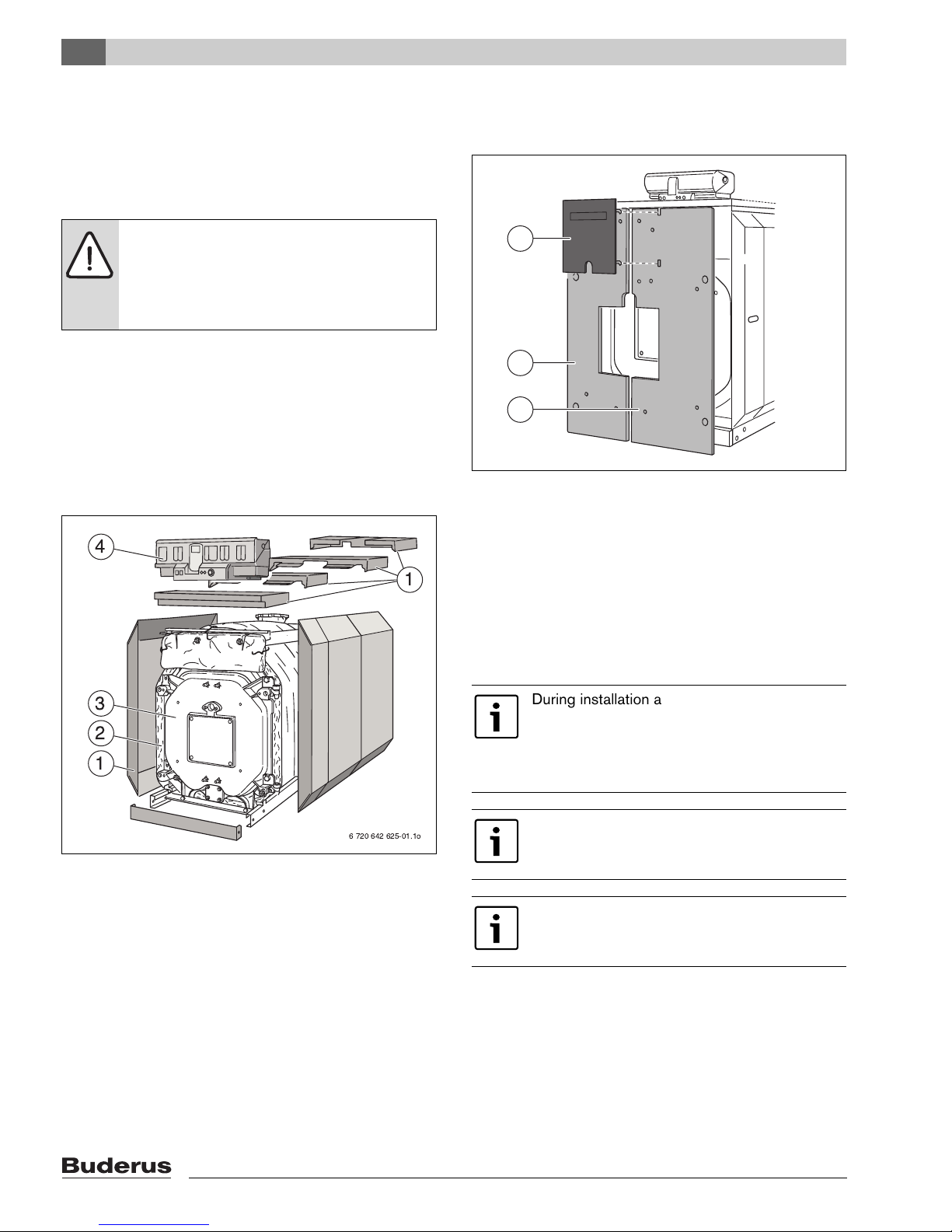
Fig. 1 Oil/gas-fired boiler Logano G615
1 Boiler shell (jacket)
2 Thermal insulation
3 Boiler heat exchanger
4 Control panel assembly
Fig. 2 Front jacket
1 Burner door panel
The Logano G615 oil/gas-fired boiler is supplied with or
without a burner You can obtain undrilled or predrilled
burner plates (hole pattern depends on burner) as
accessories from Buderus.
The predrilled burner plate is included in the scope of
delivery for the Logano G615 with oil or gas-fired fanassisted burners.
NOTICE: Risk of system damage from use of
incorrect burner.
B Only use burners that meet the technical
requirements of the oil/gas-fired boiler
Logano G615 (Æ Chapter 3, page 11).
6 720 642 625-01.1o
3
4
2
1
1
During installation and operation of the
heating system, observe all national
standards and guidelines!
Also observe the details on the boiler rating
plate.
To prevent boiler contamination, we
recommend installing a dirt trap in the water
system.
As a basic rule, flush existing systems before
connecting the boiler.
1
1
1
6 720 642 625-51.1o
Page 7
2
Product description
Logano G615 - Subject to technical modifications
7
2.1 Designated use
The Logano G615 oil/gas-fired boilers have been
designed for the heating of boiler water.
The Logano G615 can be operated with oil, gas, and
combination burners. For a list of the approved burners,
please contact Bosch Thermotechnology Corp.
This boiler can be operated with an aquastat, the
Logamatic 4000, and other control systems.
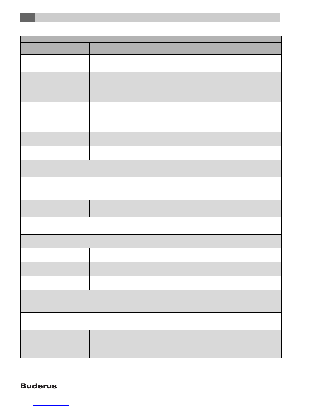
Fuels
Logano G615
Heating oil Liquid propane (LPG) Natural Gas (NG)
Remark
The Logano G615 boiler can be operated with the specified fuels. Select a burner suitable for use with the
fuels specified for the Logano G615 boiler.
The output figures shown in the Tab. “Technical Data” are nominal power figures.
Carry out maintenance and cleaning procedures annually. Check that the entire system is functioning
correctly.
Immediately remedy faults.
If heating oil is used, shorter maintenance intervals may be necessary depending on the operating time.
Tab. 2 Fuels
Page 8
2
Product description
Logano G615 - Subject to technical modifications
8
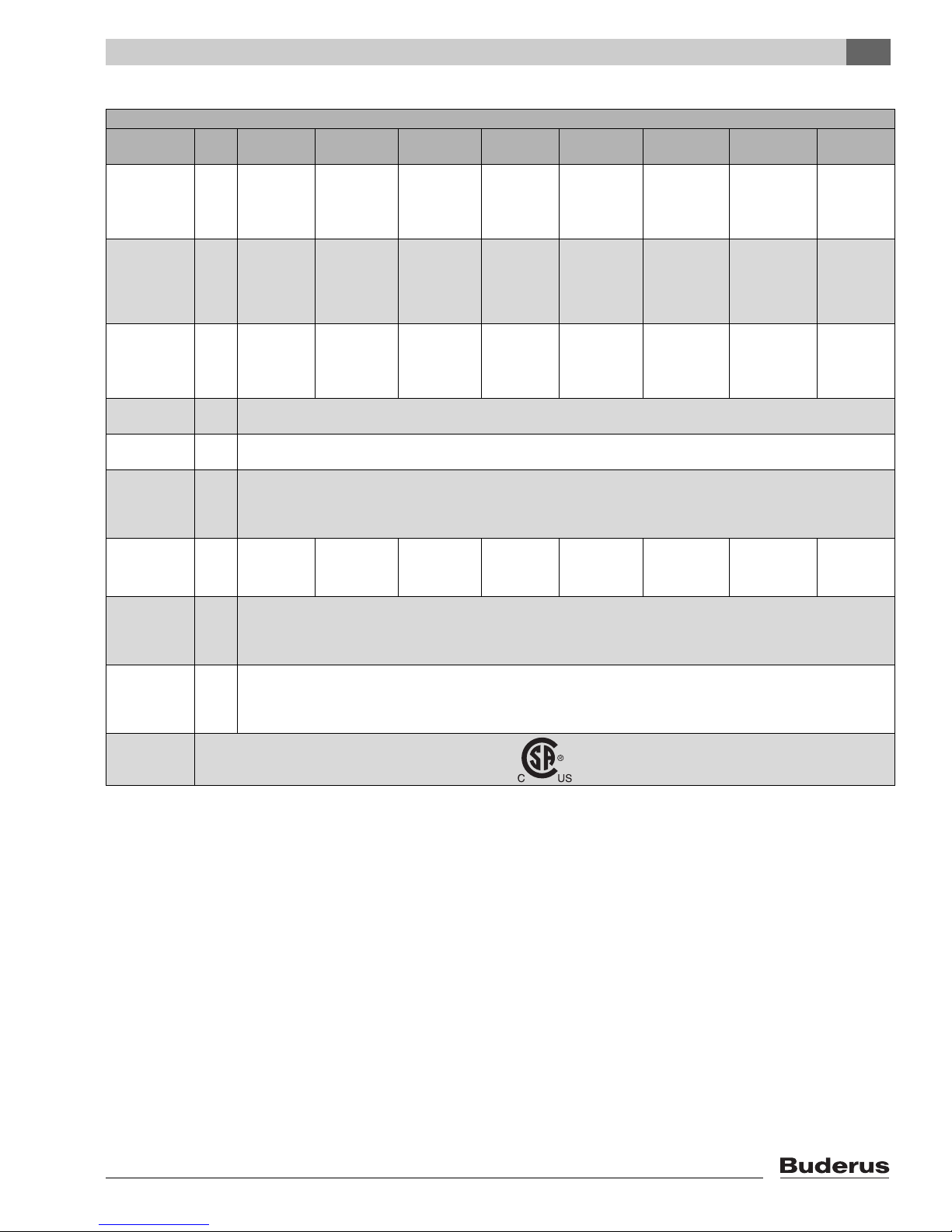
2.2 Operating conditions
Thermostream technology is a unique feature of Buderus
cast iron boilers. Return water is preheated and mixed
within the boiler before it comes in contact with the
heating surface of the combustion chamber. The
Thermostream technology ensures there is an even
temperature distribution in the boiler and avoids
condensate forming within the combustion chamber. This
unique feature reduces thermal stress, the main cause of
failure of traditional cast iron boilers. The advantage of this
technology is the maintenance of the minimum operating
temperature of the boiler (Æ Tab. 3); this makes the
installation of a shunt pump unnecessary. This way, the
costs for the pump itself and its power consumption, as
well as possible failure costs are saved. The minimum
boiler operating temperature as shown in the table below
must be reached within 10 minutes and then be
maintained while the burner is running.
This operating condition can be easily achieved by the
controls monitoring the boiler temperature and reducing
the flow rate through the boiler until the required
temperature is reached. This is then maintained by
continuing to control flow based on the boiler water
temperature. The controls can reduce the flow rate by
closing the valves on the mixed heating circuits,
modulating the boiler primary pumps, closing the
motorized butterfly valves or by having a motorized valve
in the boiler return on a single boiler installation. The
Buderus 4000 series controls can manage this process
or it can be completed by the BMS.
If it is not possible for the control panel to regulate the
flow sufficiently to meet this operating condition, then a
shunt pump circuit must be fitted to avoid the type of
thermal stress that all boilers would experience in these
conditions. This shunt pump circuit can be controlled
either with a Buderus 4000 control or with a third-party
controller. Failure to ensure that the operating condition is
maintained may lead to thermal stress in the boiler and
eventual failure of the sections which would be outside
the scope of the warranty.
Control of all heating
zones with Buderus 4000
External controls (BMS) or
with Buderus 4212 with
ZM 427 or Aquastat control
Minimum flow rate none
Minimum return temperature °F ( °C) none
Minimum operating temperature oil boiler
1)
1) This temperature has to be reached within ten minutes of the burner starting and has to be maintained whilst the burner is firing.
°F ( °C) 122 (50)
Minimum operating temperature gas boiler
1)
°F ( °C) 122 (50)
2)
2) 65 with partial load < 60 % °C
140 (60)
2)
Maximum supply temperature °F ( °C) 2123)/2484) (1003)/1204))
3) The maximum supply temperature is 212 °F (100 °C), if the boiler is operated as hot water boiler.
4) The maximum supply temperature is 248 °F (120 °C), if the boiler is operated as a hot water generator.
Maximum operating pressure PSI (bar) 87 (6)
For operation with two-stageoil and gas bumers – Set the partial load stage to 60 %
Time constant of the temperature controller sec 40
Time constant of the monitor/limiter sec 40
Tab. 3
A heating zone with a mixing valve improves
controllability and is specifically
recommended for systems with differing
water temperature zones.
Page 9

2
Product description
Logano G615 - Subject to technical modifications
9
2.3 Compliance with standards and
regulations
Installation and operation of the system must comply with
all applicable codes, regulations and statutory
requirements.
Installation, connection of the fuel supply and flue
connector, commissioning, connection of the electrical
power supply, servicing and repair may only be carried out
by a trained and certified heating contractor. Only
registered gas fitters may carry out work on the gas train.
The system must be cleaned and serviced once a year.
The operation of the complete system must be tested at
the same time. Any faults must be corrected immediately.
The design and mode of operation of this boiler comply
with the American National Standard ANSI Z21.13/
CSA4.9, latest edition for Gas Fired Low Pressure Steam
and Hot Water Boilers.
Other confirmed approvals and certifications are
indicated by labels on the boiler.
The heat exchanger has been designed and certified in
accordance with the ASME Boiler and Vessel Code,
Section IV.
Installation of the wall mounted condensing gas boiler
must comply with all applicable codes and regulations
imposed by the national, Federal or local authorities and
bodies. If no specific requirements are defined, in the
USA, the latest edition of the National Fuel Gas Code
ANSI Z223.1/NFPA 54 applies. In Canada, installation
must comply in all respects with the latest edition of the
Installation Code for Gas Burning Appliances and
Equipment, CAN/CSA-B.149 and the applicable local
regulations and requirements for the appliance category.
The relevant authorities and regulatory bodies must be
informed before installation starts.
Where required by local regulations, the system must
comply with the American Society of Mechanical
Engineers Safety Code for Controls and Safety Devices
for Automatically Fired Boilers (ASME CSD-1).
The hot water distribution system must comply with all
applicable codes and regulations. When replacing an
existing boiler, it is important to check the condition of the
entire hot water distribution system to ensure safe
operation.
In the Commonwealth of Massachusetts, this appliance
must be installed by a licensed plumber and gas fitter.
Valves external to the boiler must be fitted with T-handles
and condensate piping must be installed in accordance
with the State Plumbing Code.
Page 10

2
Product description
Logano G615 - Subject to technical modifications
10
2.4 Additional regulations for
installations in the Commonwealth
of Massachusetts
(a) For all side wall horizontally vented gas fueled
equipment installed in every dwelling, building or structure
used in whole or in part for residential purposes, including
those owned or operated by the Commonwealth and
where the side wall exhaust vent termination is less than
seven (7) feet above finished grade in the area of the
venting, including but not limited to decks and porches,
the following requirements shall be satisfied:
• INSTALLATION OF CARBON MONOXIDE
DETECTORS. At the time of installation of the side wall
horizontal vented gas fueled equipment, the installing
plumber or gasfitter shall observe that a hard wired
carbon monoxide detector with an alarm and battery
back-up is installed on the floor level where the gas
equipment is to be installed. In addition, the installing
plumber or gasfitter shall observe that a battery
operated or hard wired carbon monoxide detector with
an alarm is installed on each additional level of the
dwelling, building or structure served by the side wall
horizontal vented gas fueled equipment. It shall be the
responsibility of the property owner to secure the
services of qualified licensed professionals for the
installation of hard wired carbon monoxide detectors.
– In the event that the side wall horizontally vented gas
fueled equipment is installed in a crawl space or an
attic, the hard wired carbon monoxide detector with
alarm and battery back-up may be installed on the
next adjacent floor level.
– In the event that the requirements of this subdivision
cannot be met at the time of completion of
installation, the owner shall have a period of thirty
(30) days to comply with the above requirements;
provided, however, that during said thirty (30) day
period, a battery operated carbon monoxide
detector with an alarm shall be installed.
• APPROVED CARBON MONOXIDE DETECTORS.
Each carbon monoxide detector as required in
accordance with the above provisions shall comply
with NPA 720 and be ANSI/UL 2034 listed and IAS
certified.
• SIGNAGE. A metal or plastic identification plate shall
be permanently mounted to the exterior of the building
at a minimum height of eight (8) feet above grade
directly in line with the exhaust vent terminal for the
horizontally vented gas fueled heating appliance or
equipment. The sign shall read, in print size no less than
one-half (½) inch in size, “GAS VENT DIRECTLY
BELOW. KEEP CLEAR OF ALL OBSTRUCTIONS”.
• INSPECTION. The state or local gas inspector of the
side wall horizontally vented gas fueled equipment shall
not approve the installation unless, upon inspections,
the inspector observes carbon monoxide detectors
and signage installed in accordance with the
provisions of 248 CRM 5.08(2)(a) 1 through 4.
(b) EXEMPTIONS: The following equipment is exempt
from 248 CRM 5.08(2)(a) 1 through 4:
• The equipment listed in Section 10 entitled
“Equipment Not Required To Be Vented” in the most
current edition of NFPA 54 as adopted by the board;
and
• Product Approved side wall horizontally vented gas
fueled equipment installed in a room or structure
separate from the dwelling, building or structure used
in whole or in part for residential purposes.
(c) MANUFACTURERS REQUIREMENTS - GAS
EQUIPMENT VENTING SYSTEM REQUIRED. When the
manufacturer of Product Approved side wall horizontally
mounted gas equipment provides a venting system
design or venting system components with the
equipment, the instructions provided by the manufacturer
for the installation of the equipment and venting shall
include:
• Detailed instructions for the installation of the venting
system or the venting system components; and
• A complete parts list for the venting system design or
venting system.
(d) MANUFACTURERS REQUIREMENTS - GAS
EQUIPMENT VENTING SYSTEM NOT PROVIDED.
When the manufacturer of Product Approved side wall
horizontally vented gas fueled equipment does not
provide the parts for the venting of flue gases, but
identifies “special venting systems”, the following
requirements shall be satisfied by the manufacturer:
• The referenced “special venting systems” shall be
included with the appliance or equipment installation
instructions; and
• The “special venting systems” shall be Product
Approved by the Board, and the instructions for that
system shall include a parts list and detailed installation
instructions.
(e) A copy of all instructions for all Product Approved side
wall horizontally vented gas fueled equipment, all venting
instructions, all parts lists for venting instructions, and/or
venting design instructions shall remain with the
appliance or equipment at the completion of the
installation.
Page 11
3
Specifications
Logano G615 - Subject to technical modifications
11
3 Specifications
The technical data provides information about the output
profile of the Logano G615 .
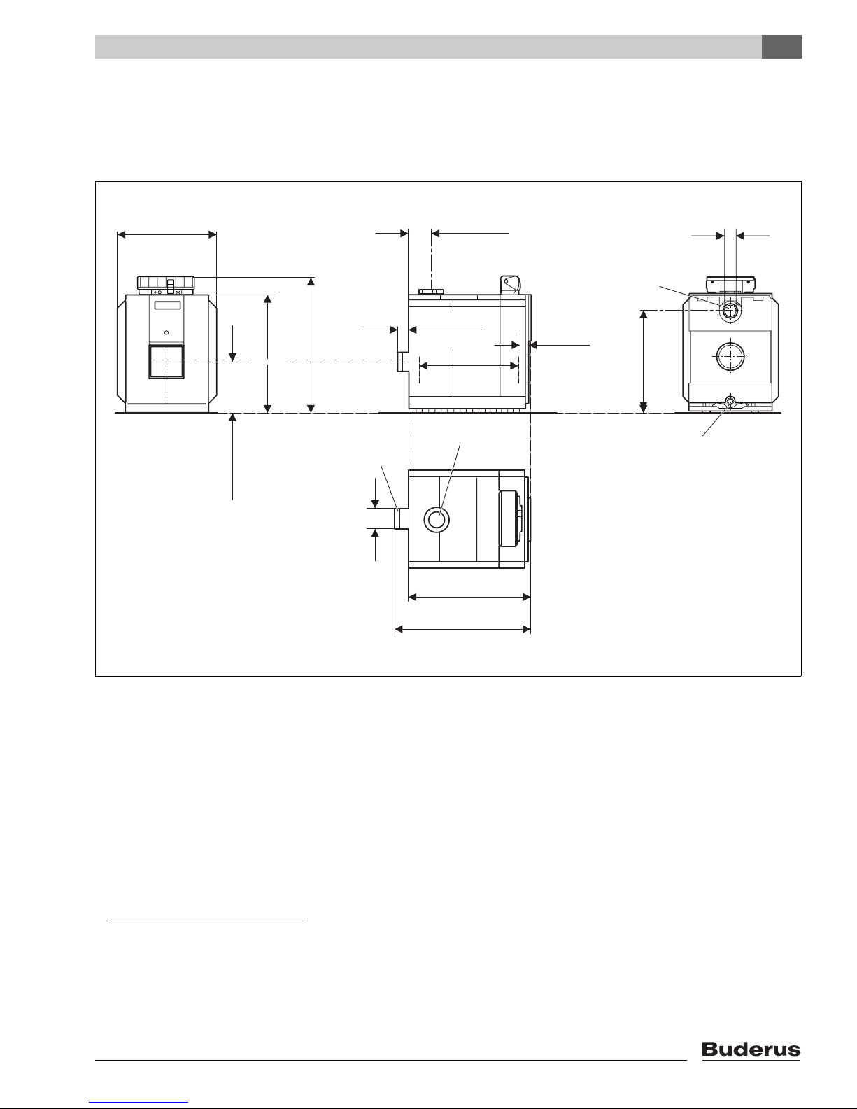
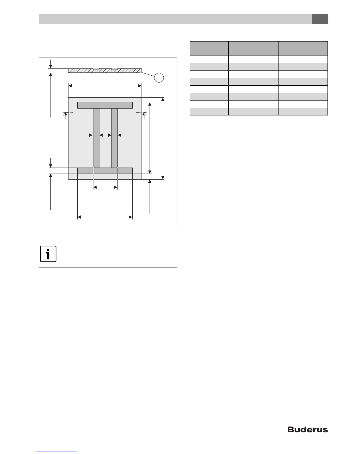
Fig. 3 Connections and dimensions
AA Flue gas spillage
EL Drain valve (Rp ¾)
1)
LKBoiler heat exchanger length
LGOverall boiler length
RK Return connection on the boiler
2)
VK Supply connection on the boiler
3)
(1390 mm)
54 23/32"
EL
RK
6 720 642 625-02.1o
L
G
VK
L
K
(125 mm)
4 59/64"
L
F
T
(750 mm)
29 17/32"
14 11/64"
(360 mm)
AA
(1826 mm)
71 57/64"
(1596 mm)
62 27/32"
(1281 mm)
50 7/16"
(350 mm)
13 25/32"
6"
(150 mm)
1) With the drain valve (EL), you may only drain the system, not fill it.
2) The filling of the boiler and the system must be undertaken on a
separate connector on the return line.
3) The flange corresponds to the order reduced to 212 (DN100), 176
(DN80) or 149 (DN65).
Page 12
3
Specifications
Logano G615 - Subject to technical modifications
12
Logano G615
Boiler
capacity
Unit 570 660 740 820 920 1020 1110 1200
Number of
boiler
sections
– 9 10 11 12 13 14 15 16
Nominal
output
Btu/hr
(kW)
1,743,604
–
1,944,921
(511 – 570)
1,948,333
–
2,252,014
(571 – 660)
2,255,426
–
2,524,984
(661 – 740)
2,528,397
–
2,797,956
(741 – 820)
2,801,368
–
3,139,170
(821 – 920)
3,142,582
–
3,480,385
(921 – 1020)
3,483,797
–
3,787,477
(1021 –
1110)
3,790,889
–
4,094,570
(1111 –
1200)
Thermal
output
Btu/hr
(kW)
1,865,077
–
2,102,562
(546.6 –
616.2)
2,083,795
–
2,434,563
(610.7 –
713.5)
2,412,384
–
2,729,713
(707.0 –
800.0)
2,704,122
–
3,024,864
(792.5 –
886.5)
2,996,202
–
3,393,716
(878.1 –
994.6)
3,360,960
–
3,760,180
(985.0 –
1102.0)
3,726,059
–
4,094,570
(1092.0 –
1200.0)
4,053,624
–
4,425,548
(1188.0 –
1297.0)
Overall boiler
length (L
G
)
inches
(mm)
75 53/64"
(1926)
82 33/64"
(2096)
89 7/32"
(2266)
95 29/32"
(2436)
102 19/32"
(2606)
109 19/64"
(2776)
115 63/64"
(2946)
122 43/64"
(3116)
Boiler block
length (L
K
)
inches
(mm)
71 1/64"
(1804)
77 23/32"
(1974)
84 13/32"
(2144)
91 7/64"
(2314)
97 51/64"
(2484)
104 31/64"
(2654)
111 3/16"
(2824)
117 7/8"
(2994)
Single boiler
section size
(B × H × T)
inches
(mm)
43 9/64" × 64 9/16" × 6 45/64"
(1096 × 1640 × 170)
Boiler block
transport
size
(B × H × L)
inches
(mm)
43 9/64" × 64 9/16" × L
K
(1096 × 1640 × LK)
Combustion
chamber
length (L
F
)
inches
(mm)
60 1/32"
(1525)
66 47/64"
(1695)
73 27/64"
(1865)
80 1/8"
(2035)
86 13/16"
(2205)
93 1/2"
(2375)
100 13/64"
(2545)
106 7/8"
(2715)
Combustion
chamber
diameter
inches
(mm)
26 49/64"
(680)
Burner door
thickness
inches
(mm)
5 4 5/64"
(145)
Weight, net 1)lbs.
(kg)
5.523
(2505)
6.056
(2747)
6.592
(2990)
7.125
(3232)
7.661
(3475)
8.179
(3710)
8.715
(3953)
9.143
(4147)
Boiler water
content
gal
(l)
148.25
(561)
164
(621)
180
(681)
195.75
(741)
211.5
(801)
227.5
(861)
243.25
(921)
259.25
(981)
Gas capacity
gal
(l)
243.5
(922)
271.25
(1027)
299
(1132)
326.75
(1237)
354.5
(1342)
382.25
(1447)
410
(1552)
437.75284
(1657)
Flue gas
temperature
partial load
60 %
°F
(°C)
284
(140)
Flue gas
temperature
full load
°F
(°C)
338 – 356
(170 – 180)
Flue gas
mass flow
rate, oil,
partial load
60 %
°F
(°C)
32.277
(0.1537)
32.32
(0.1778)
32.359
(0.1995)
32.397
(0.2207)
32.446
(0.2479)
32.495
(0.275)
32.539
(0.2992)
32.582
(0.3234)
Tab. 4 Technical data and dimensions
Page 13
3
Specifications
Logano G615 - Subject to technical modifications
13
Flue gas
mass flow
rate oil, full
load
2)
lbs./s
(kg/s)
0.5115 –
0.5765
(0.232 –
0.2615)
0.5714 –
0.6676
(0.2592 –
0.3028)
0.6616 –
0.7487
(0.3001 –
0.3396)
0.7416 –
0.8296
(0.3364 –
0.3763)
0.8217 –
0.9308
(0.3727 –
0.4222)
0.9218 –
1.0313
(0.4181 –
0.4678)
1.0218 –
1.1228
(0.4635 –
0.5093)
1.1118 –
1.2136
(0.5043 –
0.5505)
Flue gas
mass flow
rate, gas,
partial load
60%
lbs./s
(kg/s)
0.34
(0.1542)
0.3935
(0.1785)
0.4414
(0.2002)
0.4883
(0.2215)
0.5485
(0.2488)
0.6085
(0.276)
00.662
(0.3003)
0.7156
(0.3246)
Flue gas
mass flow,
gas, full
load
2)
lbs./s
(kg/s)
0.5132 –
0.5787
(0.2328 –
0.2625)
0.5736 –
0.67
(0.2602 –
0.3039)
0.664 –
0.7513
(0.3012 –
0.3408)
0.7443 –
0.8325
(0.3376 –
0.3776)
0.8247 –
0.9341
(0.3741 –
0.4237)
0.9251 –
1.0348
(0.4196 –
0.4694)
1.0256 –
1.127
(0.4652 –
0.5112)
1.1158 –
1.2181
(0.5061 –
0.5525)
CO2 content,
oil
% 13
CO2 content,
gas
%10
Required flue
pressure
(draft
requirement)
PSI
(Pa)
0
(0)
Fireside
pressure
drop
in
W.C.
(mbar)
0.9624
(2.4)
1.3634
(3.4)
1.6842
(4.2)
1.6842
(4.2)
1.6441
(4.1)
1.8045
(4.5)
2.1654
(5.4)
2.3258
(5.8)
Permissible
supply
temperature
3)
°F
(°C)
212 – 248
(100 – 120
4)
Allowable
operating
water
pressure
PSI
(bar)
87
(6)
1) Weight not incl. packaging material approx. 4 – 5 % less.
2) The details relate to the upper and lower rated output range.
3) Safety limit (high limit safety cut-out). Maximum possible supply temperature = safety limit (STB) – 32 °F ( – 18 K).
Example: Safety limit (STB) = 212 °F (100 °C), max. possible supply temperature = 212 – 32 = 180 °F (100 – 18 = 82 °C).
4) Observe all gas regulations and requirements for your country.
Logano G615
Boiler
capacity
Unit 570 660 740 820 920 1020 1110 1200
Tab. 4 Technical data and dimensions
Page 14
4
Scope of delivery
Logano G615 - Subject to technical modifications
14
4 Scope of delivery
The boiler can be delivered either as a pre-assembled
block or in loose sections.
B After delivery, check all packaging for perfect
condition.
B Check the delivery for completeness.
4.1 Logano G615 – Delivery as a preassembled block
4.2 Logano G615 – Delivery in loose
sections
5 Transporting the boiler
Use suitable equipment to transport the individual boiler
sections (delivery as loose sections) and other individual
parts.
Component Qty Packaging
Boiler heat exchanger 1 Pallet
Fittings 1 Crate
Assembly parts 1 Crate
Jacket pack A 1 Crate
Jacket pack B 1 Crate
Thermal insulation 1 Foil pouch
Tab. 5 Scope of delivery (block delivery)
Component Qty Packaging
Front, rear, intermediate
section with top supply
connection and burner door
1 Pallet
Central sections (depending
on boiler size)
2– 5 Pallet
Fittings basic unit, 9 – 16
pieces
1Crate
Additional fittings (content
depends on boiler size)
1 Crate
Assembly parts 1 Crate
Jacket pack A 1 Crate
Jacket pack B 1 Crate
Thermal insulation 1 Foil pouch
Tie rods set with spring
packages
Tab. 6 Scope of supply (loose sections)
WARNING: Risk of injury from improperly
secured boiler sections.
B Use only suitable means of transportation
when handling the boiler sections, e.g. a
sack truck with strap or heavy duty dolly.
B Secure the individual boiler sections to
prevent them from sliding off when
transporting them.
NOTICE: Risk of system damage from
impacts.
B The standard delivery of the Logano G615
oil/gas-fired boiler contains components
that are sensitive to shock.
B During handling protect all electronic and
other components against impact.
B Please observe the transport instructions
on the packaging.
NOTICE: Risk of system damage from
contamination.
B If you intend to keep the boiler in storage
once it has been assembled, observe the
following:
B Protect the boiler connections against
contamination by sealing them off or
covering them.
Dispose of packaging in an environmentally
responsible manner.
Page 15

6
Positioning the boiler
Logano G615 - Subject to technical modifications
15
6 Positioning the boiler
This chapter describes how to properly position the
Logano G615.
6.1 Tools and auxiliary materials
The following tools and auxiliary materials are required for
the boiler assembly (the listed items are not contained in
the scope of delivery).
• Boiler assembly tool 2.3
• Installation kit (accessory)
• Steel hammer and wooden or rubber mallet
• Half-round bastard file
• Screwdriver (Philips and flat head)
• Flat chisel, support wedge, flat iron
• Metric wrenches
• Cleaning rags and cloth
• Fine emery cloth
•Wire brush
•3-in-1 oil
• Solvent (gasoline, mineral spirits)
• Level, tape measure, chalk, straight edge
Boiler assembly tool size 2.3
Fig. 4 Boiler assembly tool size 2.3 (dimensions in
mm)
1 Mating flange
2 Additional flange
3 Compression unit
4 Tie rod
5 Extension
6 Wedge (size 2.3)
L
1
121 1/4" (3080 mm)
L
2
31 1/2" (800 mm)
NOTICE: Risk of system damage from
freezing.
B Install the system in a room free from the
danger of freezing.
Boiler
sections
Assembly
tool(s) per
boiler hub
Extension
piece per
boiler hub
Length
(total) in
inches
(mm)
9– 16 1 3
121 1/4
(3080)
Tab. 7 Boiler assembly tool size 2.3 (complete in the
toolbox)
For the correct arrangement of the flange
when performing the assembly procedure,
refer to page 21.
6 720 642 623-03.1o
3 2 1
6
4 5
L
1
L
2
L
2
Page 16
6
Positioning the boiler
Logano G615 - Subject to technical modifications
16
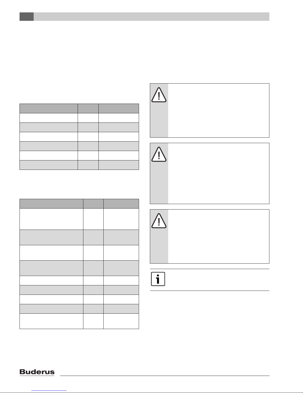
6.2 Recommended wall clearances
Fig. 5 Installation room with boiler
The burner door can be hung with the hinges on the right
or left.
The wall clearance on the hinge side must be at least the
burner projection (AB). A distance of AB + 4"
(AB + 100 mm) from the wall is recommended.
If you do not observe the recommended minimum wall
clearances, you will not be able to use the cleaning kit.
Alternatively shorter cleaning devices or wet cleaning may
be used.
Observe the recommended wall clearances
for complete opening of the burner door, for
boiler installation and for cleaning and
maintenance (Æ Fig. 5 and Tab. 8).
6 720 642 625-03.1o
L
K
(400 mm)
≥ 15 3/4"
(1281 mm)
50 7/16"
(AB+100 mm)
AB + 4"
AB
A
(~ 1150 mm)
45 1/4"
50 7/16"
≥
15 3/4"
45 1/4"
Boiler capacity Clearance A inch (mm)
BTU/h (kW) Sections Recommended minimum
1,944,921 –
2,797,956
(570 – 820)
9– 12 90 35/64"
(2300)
55 1/8"
(1400)
3,139,170 –
4,094,570
(920 – 1200)
13 – 16 118 7/64"
(3000)
59 1/16"
(1500)
Tab. 8 Recommended and minimum wall clearances
Page 17
6
Positioning the boiler
Logano G615 - Subject to technical modifications
17
6.3 Installing the boiler on a boiler base
or foundation
Fig. 6 Base dimensions
Place the boiler on a 2 – 4 inch (450 – 100 mm) tall base
(observe wall clearances). The base must be flat and level.
The front edge of the boiler should be flush with the edge
of the base.
When pouring a foundation for the boiler, use the steel
inserts with the following dimensions:
3 15/16 × 1 31/32 × 5/16 inches (100 × 50 × 8 mm)
or sheet metal with the dimensions
3 15/16 × 13/64 inches (100 × 5 mm).
A silencing boiler base is available as an
accessory from Buderus.
6 720 642 621-01.1o
L
2
(820 mm)
(~ 100 mm)
(100 mm)
(~ 1160 mm)
(~ 50...100 mm)
2...4"
L
1
34 3/4"
1
4"
4"
32 9/32"
(410 mm)
16 9/64"
(100 mm)
4"
16 9/64"
34 3/4"
32 9/32"
Number of
boiler sections
L1 (base)
inch (mm)
L2 (steel section)
inch (mm)
9 65 3/4“ (1670) 57 7/8“ (1470)
10 72 7/16“ (1840) 64 9/16“ (1640)
11 79 9/64“ (2010) 71 1/4“ (1810)
12 85 53/6“4 (2180) 77 61/64“ (1980)
13 92 33/64“ (2350) 84 41/64“ (2150)
14 99 7/32“ (2520) 91 11/32“ (2320)
15 105 29/32“ (2690) 98 1/32“ (2490)
16 112 19/32“ (2860) 104 23/32“ (2660)
Tab. 9 Base dimensions for angle or sheet metal steel
lengths
Page 18
7
Boiler block assembly
Logano G615 - Subject to technical modifications
18
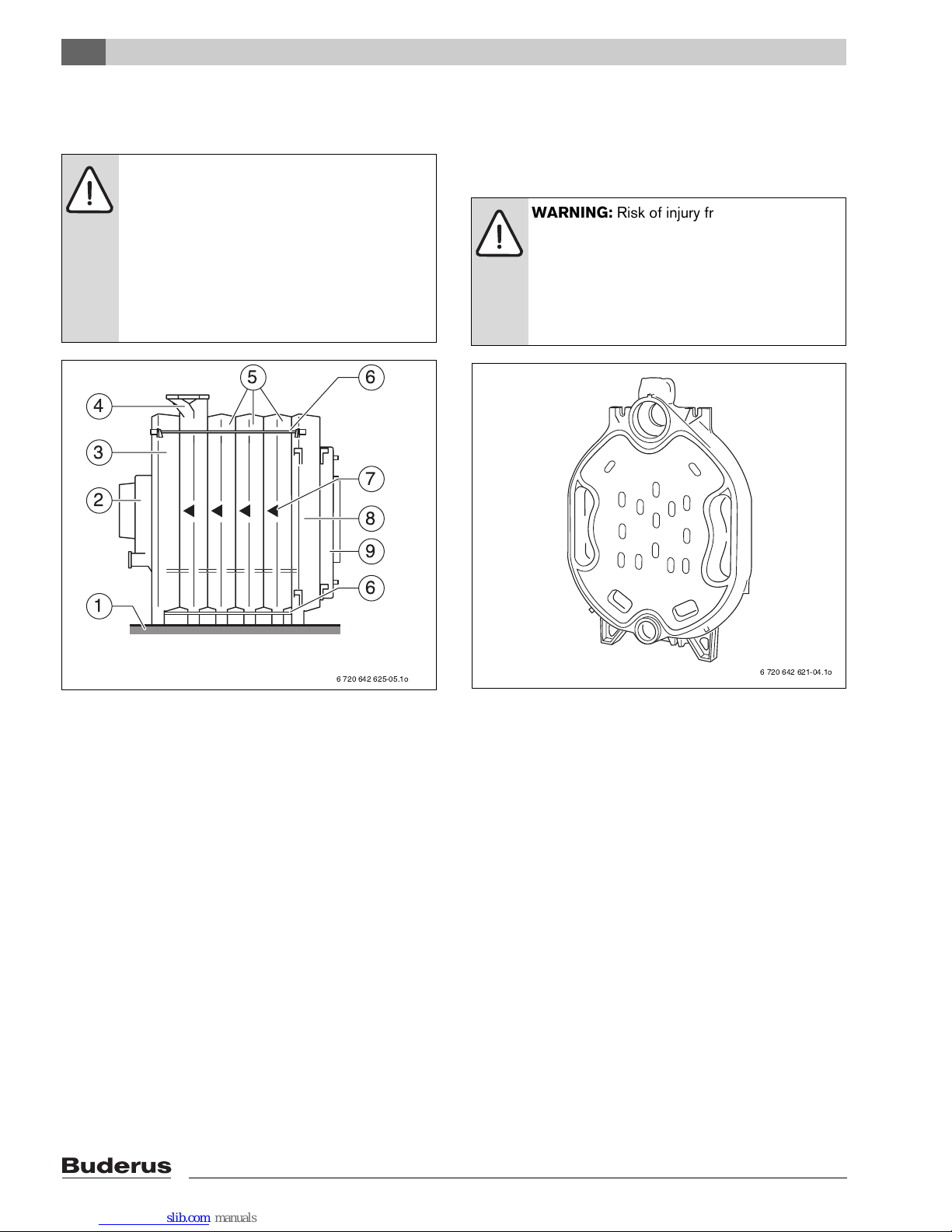
7 Boiler block assembly
Fig. 7 Assembled boiler block
1 Boiler base or foundation
2 Draft diverter
3 Rear section
4 Intermediate section with supply connection
5 Intermediate section
6 Tie rod
7 Sequence of installation
8 Front section
9 Burner door with burner plate
A distinction is made between delivery as a preassembled block and delivered as disassembled
sections. When delivered as a block, the boiler sections
are already fully assembled and checked for leaks prior to
delivery. If the assembled boiler is too large or too heavy
to be brought to its final installation location in the
building, delivery of the disassembled boiler in sections
offers a solution.
The assembly of the boiler block from individual sections
is described below.
For details on final assembly of the remainder of the boiler,
Æ see Chapter 7.3, page 23.
7.1 Assembly of a boiler block from
sections
Fig. 8 Rear section
The assembly of the boiler block is always done from the
rear to the front, that is, the rear section (Æ Fig. 7, [3]) is
always mounted first and the front section (Æ Fig 7, [8])
is always mounted last.
Observe the installation direction arrows of the boiler
sections (Æ Fig. 7, [7]) during assembly!
Observe the correct positioning of the intermediate
section with top supply connection (Æ Fig. 7, [4])!
Mount the boiler block according to the instructions and
figures below!
WARNING: Risk of injury from improperly
secured boiler sections.
B Use only suitable means of transportation
when handling the boiler sections, e.g. a
heavy duty hand truck with strap or a
heavy duty hand truck.
B Secure the individual boiler sections to
prevent them from sliding off during
transport.
6 720 642 625-05.1o
1
2
3
4
6
6
7
9
8
5
WARNING: Risk of injury from insufficiently
secured boiler sections.
B Secure boiler sections during assembly
and take measures to prevent them from
tipping over. The installation aid
(accessory) is available from Buderus on
request.
6 720 642 621-04.1o
Page 19
7
Boiler block assembly
Logano G615 - Subject to technical modifications
19
7.2 Joining the boiler block assembly
(delivery as loose sections)
Preparing boiler sections
B Remove nuts and washers from the studs on the hubs
of the boiler sections before attaching the rear section
and front section.
B Put the rear section in place and secure during
assembly taking measures to prevent tipping over (Æ
Fig 8 and separate instructions for installation).
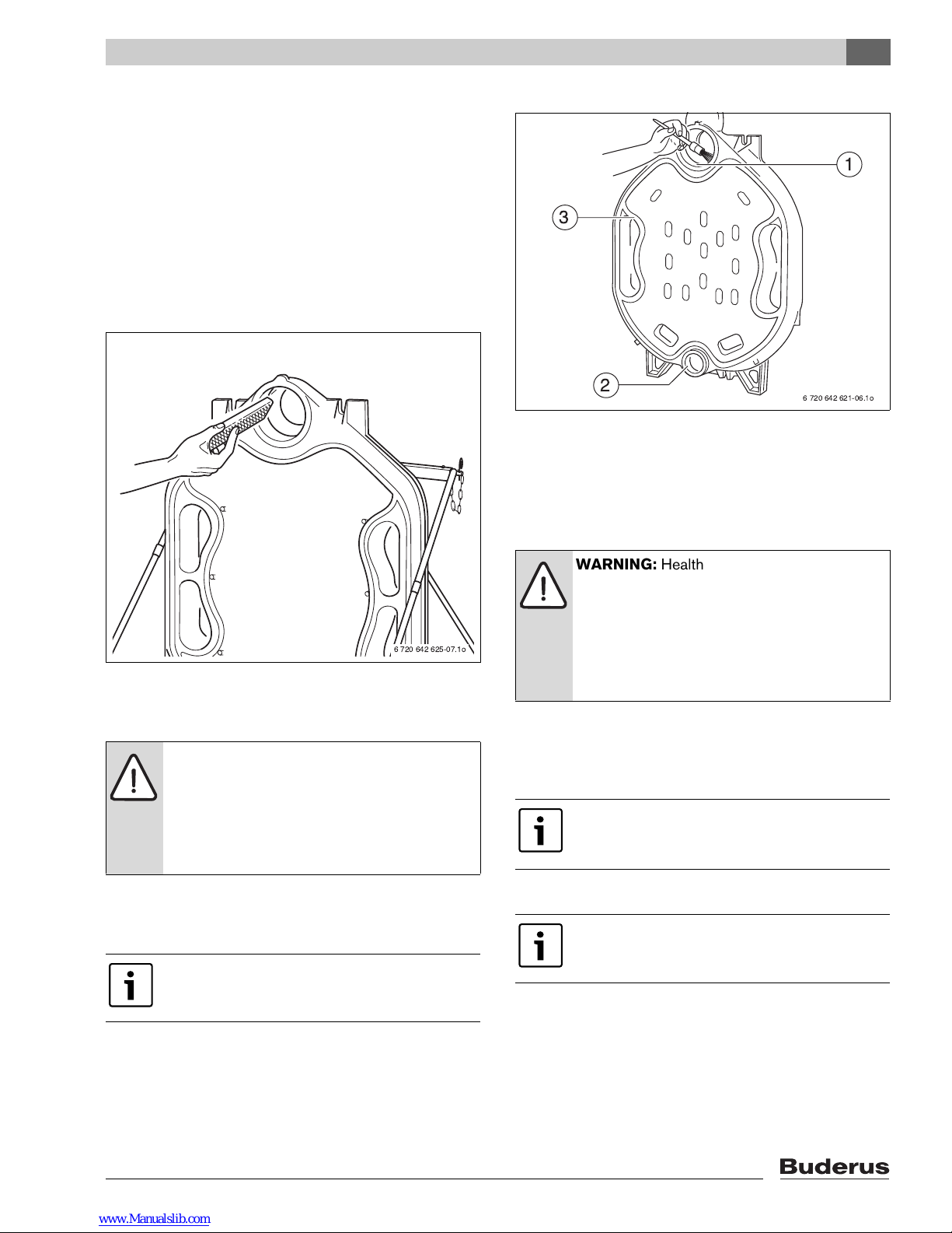
B File down any burrs on the hubs if necessary.
Fig. 9 Filing down burrs on the hub
B Clean the packing grooves where required using a wire
brush and cloth.
B Clean the hub sealing faces with a rag soaked in
solvents or gasoline.
B Evenly coat the hub sealing faces with sealant.
Fig. 10 Coating the hub sealing faces
1 Sealing face of top hub
2 Sealing face of bottom hub
3 Packing groove
B Clean nipple with a rag soaked in solvents or gasoline
and coat evenly with sealant.
B Insert nipple directly into the top (size 4, 181/70) and
bottom (size 2, 119/50) hub on the rear section.
B Strike the nipple with hefty hammer strokes in a cross
pattern.
B Remove any burrs with a file.
WARNING: Danger of fire from combustible
cleaning agents.
B When using solvents, avoid open flames,
ambers and sparks.
B Please observe the safety instructions
regarding any solvents used.
The next step involves preparing the nipples
that will eventually seal the boiler sections.
6 720 642 625-07.1o
WARNING: Health hazard from noxious
vapors released during material handling,
such as solvents, primers or sealant.
B Ensure adequate ventilation of the
installation area.
B Please note the handling and safety
instructions of the product used.
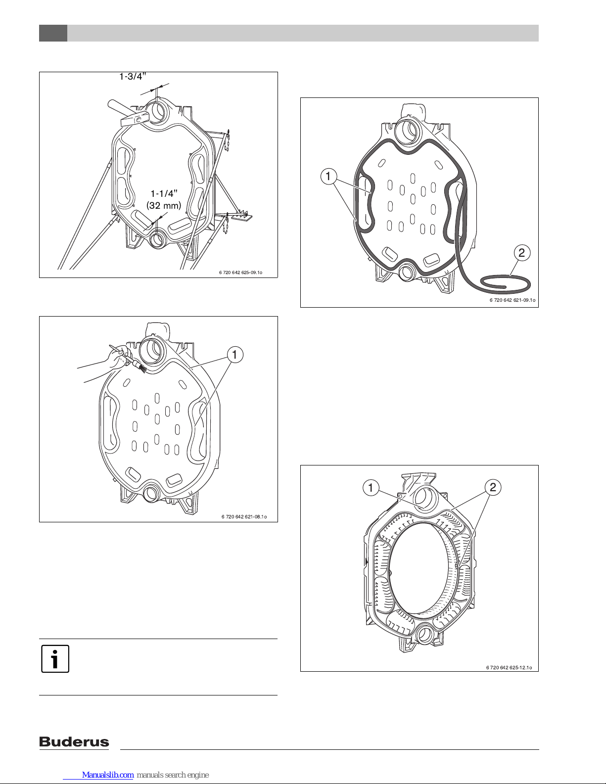
The top nipple must protrude approx. 1 3/4"
(43 mm) and the bottom nipple approx. 1 1/4"
(32 mm) out of the corresponding hubs.
The packing grooves must be clean and dry
for the sealant rope to adhere properly.
6 720 642 621-06.1o
2
3
1
Page 20
7
Boiler block assembly
Logano G615 - Subject to technical modifications
20
Fig. 11 Driving nipples home
B Coat the packing grooves with adhesive (primer).
Fig. 12 Coat the packing grooves with adhesive
(primer)
1 Packing grooves
B Insert the flexible sealant rope on the front of the rear
section, starting around the top hub, into the packing
grooves, and press in lightly.
B At the butt joints, overlap the sealant rope by approx.
3/4" (20 mm) and press firmly together.
B Do not let sealant rope overlap at the left and right of
the butt joints (Æ Fig. 13, [3]).
Fig. 13 Inserting sealant rope
1 Packing grooves
2 Sealant rope
3 Butt joints
Prepare the first intermediate section (with top
supply connection):
B File down any burrs on the hub.
B The packing springs must be clean and dry. Clean if
necessary.
B Clean the hub sealing faces with a rag soaked in
mineral spirit or gasoline.
Fig. 14 Preparing the center section
1 Sealing face of the hub
2 Packing springs
Unroll the required length of sealant rope
from the spool supplied. Peel the backing
paper from the sealant rope when inserting
into the packing groove (do not stretch).
6 720 642 625-09.1o
43
32
1-1/4"
(32 mm)
1-3/4" (43 mm)
6 720 642 621-08.1o
1
6 720 642 621-09.1o
2
1
6 720 642 625-12.1o
2
1
Page 21
7
Boiler block assembly
Logano G615 - Subject to technical modifications
21
B Evenly coat the hub sealing faces with sealant.
B Coat the packing springs with primer.
B Position the intermediate section with the supply
connection so that the top and bottom hubs fit onto the
nipples in the rear section. The directional arrow must
point towards the rear.
B Drive first intermediate section onto the rear section
using a wooden or a rubber mallet.
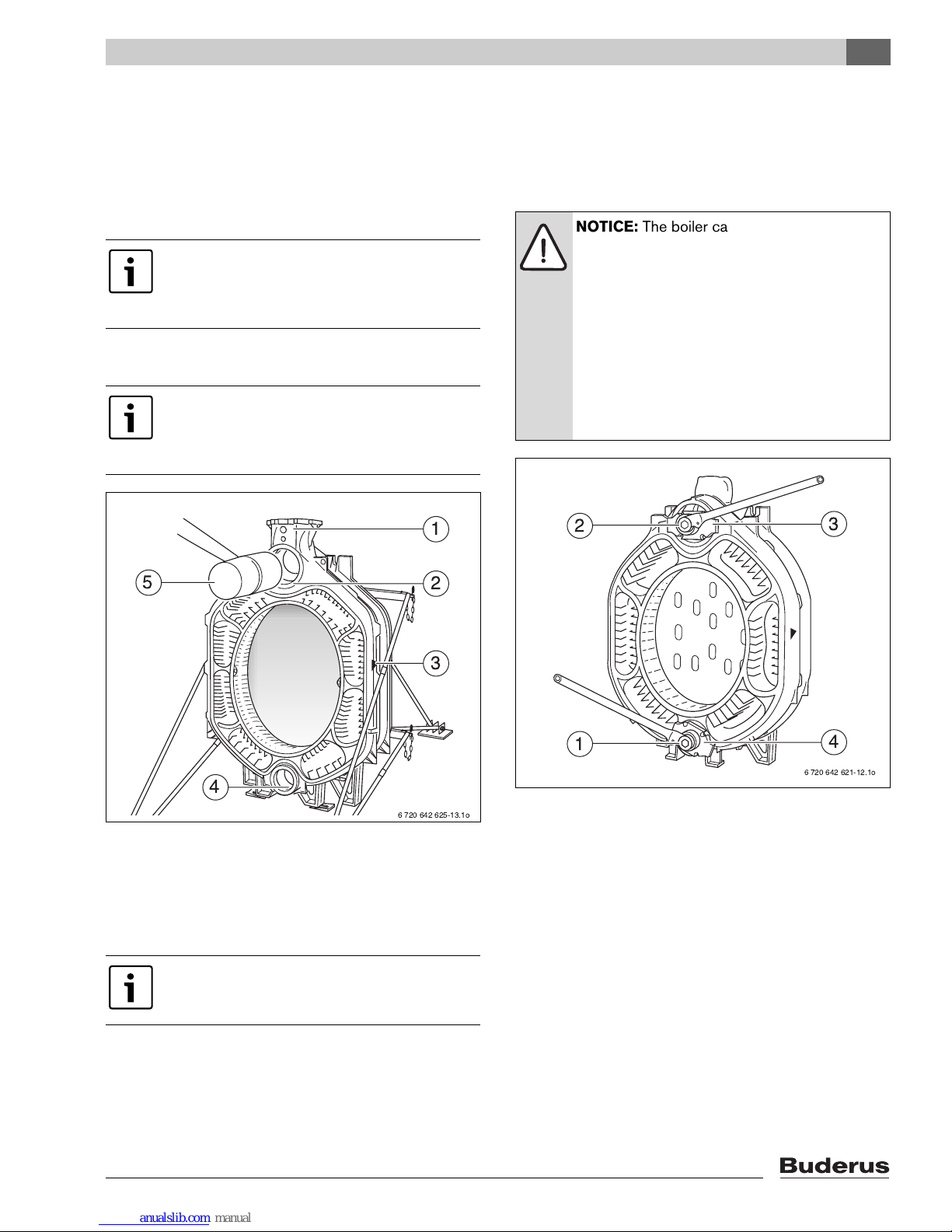
Fig. 15 Pound intermediate section in place
1 Supply connection
2 Top hub
3 Directional arrow
4 Bottom hub
5 Wood or rubber mallet
B Push pressure flange with clamping nuts onto the tie
rods.
B Push a tie rod through the top and bottom hubs on the
boiler block.
B Push mating flanges onto the tie rods and secure each
with wedge.
B Hold the tie rod in the center of the hubs and slightly
draw together the compression tools using the
clamping nut.
Fig. 16 Using the boiler assembly tool
1 Boiler assembly tool (bottom hub)
2 Boiler assembly tool (top hub)
3 Pressure flange (top)
4 Pressure flange (bottom)
B Place ratchet wrench onto clamping nut and compress
boiler sections by tightening evenly.
To make installation easier, place the boiler
section to be fitted onto the nipple on the top
hub first. Then it is easier to align the boiler
section on the bottom hub.
Before the nipples are inserted in the next
intermediate section, the partly-assembled
boiler block must be compressed using the
boiler assembly tool.
Use boiler assembly tool 2.3 (Æ Fig. 4,
page 15).
6 720 642 625-13.1o
1
2
3
5
4
NOTICE: The boiler can be damaged by
pulling the boiler sections together
incorrectly or due to excessive compression.
B Ensure that the nipples are positioned
straight in the boiler hubs after being
pounded in and that they have not been
compromised.
B Never compress more than one nipple
joint at a time.
B Stop compressing the sections when the
boiler hubs meet.
6 720 642 621-12.1o
3
4
1
2
Page 22
7
Boiler block assembly
Logano G615 - Subject to technical modifications
22
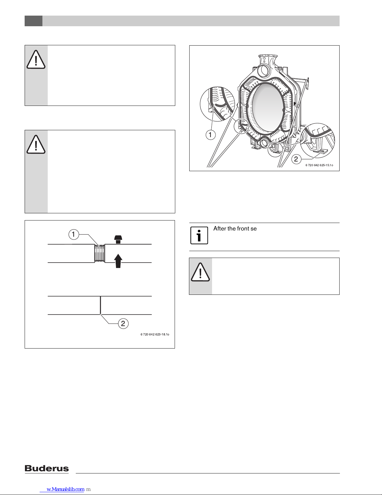
B Release and remove the boiler assembly tool.
B Check nipples are seated correctly.
Fig. 17 Boiler assembly tool 2.3
1 Screw connection of the tie rods (disassembled)
2 Screw connection of the tie rods (correctly positioned)
Fig. 18 shows the intermediate section with supply
connection. The nipples for mounting of the next
intermediate section are inserted into the corresponding
hubs. The sealant rope has already been inserted into the
packing groove. As shown for the rear section (Æ Fig. 13,
page 20), here too, the flexible sealant rope is interrupted.
The boiler section has been equipped with foot wedges
for ease of installation. The boiler section foot wedges are
also used later for final leveling of the boiler block.
Fig. 18 Using the boiler section foot wedges
1 Sealant rope (interrupted)
2 Boiler section foot wedge
Assemble all other boiler sections as described. The front
section is fitted last.
B Insert the tie rods (with spring packages fitted) into the
cast lugs on the top left and right, and bottom left and
right, next to the boiler block hubs.
B Turn and tighten each nut on the tie rods by hand.
B Now tighten the nuts on the tie rods 1 to 1½ turns.
B Level the boiler block vertically and horizontally on the
base/foundation (Æ see Chapter 6.3, page 17). Use
the boiler section foot wedges provided for this
purpose (Æ Fig. 18, page 22).
CAUTION: Danger of accident from material
fatigue. Improperly used or poorly maintained
assembly tools may fail.
B Never work directly in front of the
assembly tool while it is being tensioned.
B Ensure that no one is standing in front of
the assembly tool.
NOTICE: Assembly tool damage due to
loose screw connections of the tie rods.
B Always check the tie rods before each use
and retighten as necessary. The tie rod is
correctly positioned if it is fully inserted
and no threads are showing (Æ Fig. 17,
[2]).
B Always keep the threads (Æ Fig. 17, [1])
clean. Dirty threads may damage the
assembly tool during compression.
6 720 642 623-18.1o
1
2
After the front section is attached, loosen the
assembly tool but do not remove it. First
insert the tie rods.
NOTICE: Damage to system through
excessively low contact pressure.
B Do not compress the spring pack. Only
use the spring pack in its original state.
6 720 642 625-15.1o
1
2
Page 23
7
Boiler block assembly
Logano G615 - Subject to technical modifications
23
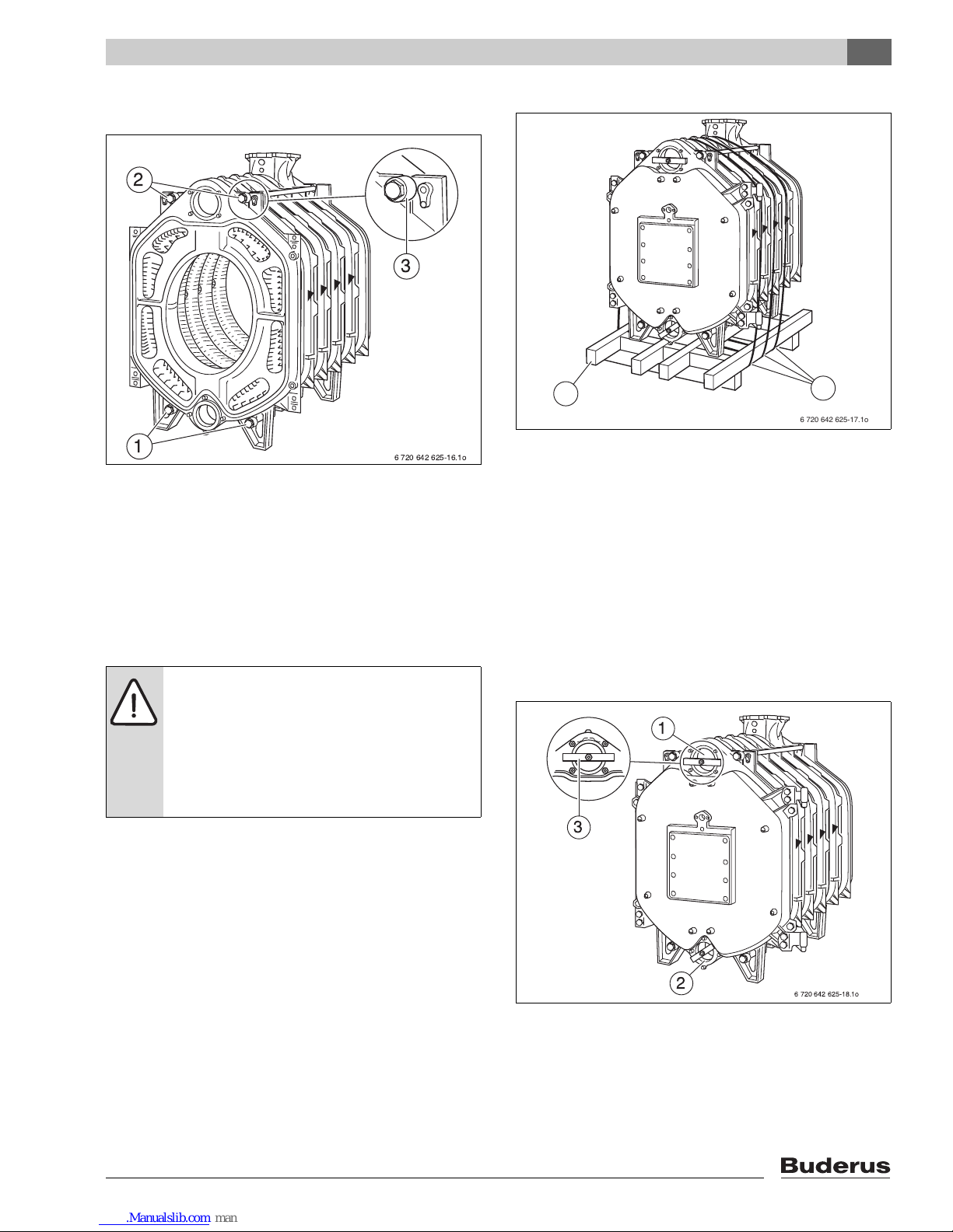
B Remove boiler assembly tool.
Fig. 19 Inserting the tie rods
1 Tie rods (bottom)
2 Tie rods (top)
3 Tie rod with spring package
The next step describes the installation of the supply pipe
(Æ see Chapter 7.4, page 24).
7.3 Setting up the boiler block –
(assembled block)
B Cut the straps.
B Remove pallet.
Fig. 20 Boiler block on pallet
1 Securing straps
2 Pallet
B Level the boiler block vertically and horizontally on the
base/foundation. Use the boiler section foot wedges
provided for this purpose.
B After leveling the boiler block, remove the transport
safety brace from the top and bottom hub.
The following pages describe the installation of the supply
pipe and sensor well. You must do both irrespective of
whether the boiler is supplied pre-assembled or in
separate sections.
Fig. 21 Removing the transport safety brace
1 Top hub
2 Bottom hub
3 Transport safety brace
DANGER: Risk of fatal injury from falling
objects.
B Provide a suitable means of supporting
the load.
B Observe all locally applicable
occupational health & safety regulations
regarding lifting equipment.
6 720 642 625-16.1o
1
2
3
6 720 642 625-17.1o
2
1
6 720 642 625-18.1o
3
1
2
Page 24

7
Boiler block assembly
Logano G615 - Subject to technical modifications
24
7.4 Inserting the supply pipe (parts
crate)
For boilers with 9 – 11 sections, the supply pipe consists
of 2 pieces, and 12 – 16 sections 3 pieces.
B Push the flat gasket over the supply pipe.
B Push the supply pipe from the front into the top boiler
hub.
B Close off with flange cover.
Fig. 22 Sealing in the supply pipe
1 Flat gasket
2 Flange cover
3 Cam
4 Supply pipe
5 Notch in top boiler hub
7.5 Installing sensor well (fittings crate)
Sensor well R ¾ "
B Seal and install sensor well R ¾ " from the front
(length: 4 21/64" (110 mm)) into the top R ¾ " tapped
hole of the supply connection.
Sensor well R ½ "
B Seal and install sensor well R ½ " from the front
(length: 4 21/64" (110 mm)) into the lower R ½ "
tapped hole of the supply connection.
Fig. 23 Installing sensor wells
1 Sensor well R ¾ "
2 Sensor well R ½ "
The supply pipe must be fixed in such a way
that the holes on the supply pipe are
positioned at the correct angle. This ensures
optimum distribution of water in the area of
the top boiler hub (Thermostream principle).
B Make sure that the cam [3]) on the end
plate of the supply pipe (Æ Fig. 22, [3]) fits
in the notch in the top boiler hub
(Æ Fig 22, [5]).
6 720 642 625-19.1o
2
5
5
1
43 3
6 720 642 625-20.1o
2
1
Page 25
7
Boiler block assembly
Logano G615 - Subject to technical modifications
25
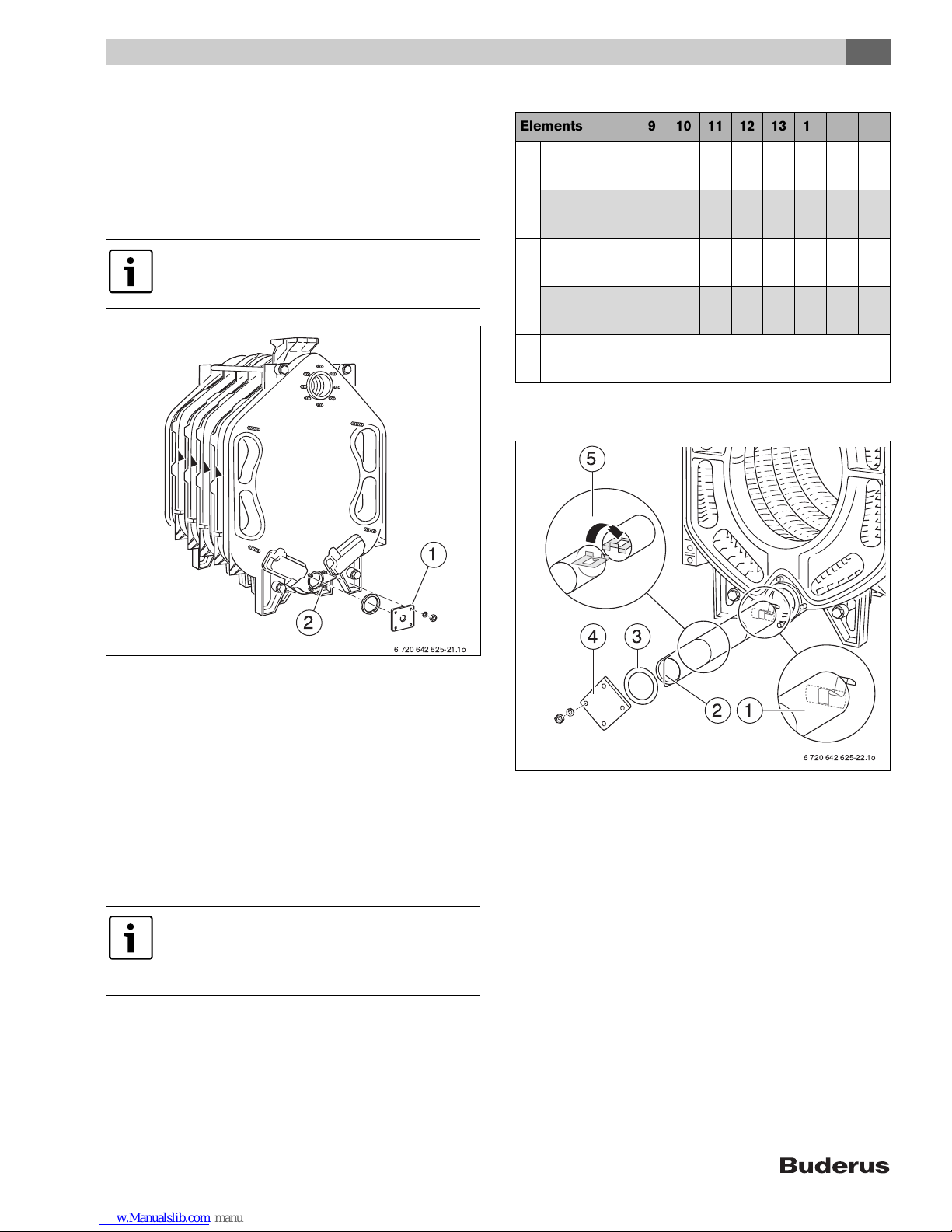
7.6 Inserting the lower distribution tube
(fittings crate)
B Mount the tapped hole for the drain connection on the
bottom boiler hub behind the flange
(edge length 5 – 1/8" (130 mm)) with R ¾ ".
B Fit customer-supplied boiler drain valve.
Fig. 24 Fitting the flange
1 Fill and drain connection
2 Bottom boiler hub (rear)
B Push the lower distribution tube element with spring
(L
3
) into the bottom boiler hub first.
B Hook the other lower distribution tube elements (L
2
)
into one another according to the detailed drawing.
B As the last lower distribution tube element, hook in the
one with the handle (L
1
).
B Close off bottom boiler hub with flat gasket and flange
cover.
Fig. 25 Inserting the lower distribution tube
1 Lower distribution tube element L
3
2 Lower distribution tube element L
1
3 Flat gasket
4 Flange cover
5 Lower distribution tube element L
2
The customer-supplied boiler fill and drain
valve is only used as a drain valve here.
The length and number of the lower
distribution tube elements depends on the
boiler size and can be determined using
Æ Table 10 below.
6 720 642 625-21.1o
2
1
Elements 9 10 11 12 13 14 15 16
L
1
18 29/32"
(480 mm)
1– – 1– 1– –
25 19/32"
(650 mm)
– 1 1 – 1 – 1 1
L
2
20 5/64" (510
mm)
1 1 – 2 2 – – 3
26 49/64"
(680 mm)
– – 1 – – 2 2 –
L
3
17 23/32"
(450 mm)
1
Tab. 10 Length and number of the lower distribution
tube elements
6 720 642 625-22.1o
12
34
5
Page 26

7
Boiler block assembly
Logano G615 - Subject to technical modifications
26
7.7 Leak test
Conduct a leak test of the boiler block only when the
boiler was delivered disassembled. Pre-assembled
blocks are leak tested at the factory.
For details of assembling the remainder of the boiler if the
block is delivered pre-assembled Æ see Chapter 7.9.4,
page 29.
7.7.1 Carrying out leak test
The leak test must be performed with a test pressure of
125 psi (8.6 bar). Use a suitable pressure gauge to
measure the pressure.
B Drain the water from the fill and drain valve (Æ Fig. 24,
[1], page 25), at the water supply connection, or at a
leaky hub connection.
B Close off supply and return connections (supply
connection flange with air vent valve).
B Slowly fill the boiler block with water via the fill and
drain connection. Purge the air from the boiler block via
the boiler supply connection with purger.
7.7.2 Seal leaks.
If leaky hub connections are discovered during the
pressure test, proceed as follows.
B Remove supply pipe and lower distribution tube.
B Undo nuts on tie rods and remove tie rods.
B Separate the boiler block at the leak location by driving
(knocking) in flat wedges or chisels between the
sections at the points provided at the top and bottom
(Æ Fig. 26).
Fig. 26 Separating the boiler block
WARNING: Danger of life from neglecting to
follow safety regulations.
B Observe the applicable national
standards, occupational safety provisions
and regulations for executing leak tests.
NOTICE: Risk of system damage from
overpressure.
B Ensure that no pressure, control or safety
equipment is fitted during leak tests.
Use new nipples and new sealant rope for
the reassembly.
B Pull the boiler back together and repeat
the leak test.
6 720 642 625-23.1o
Page 27

7
Boiler block assembly
Logano G615 - Subject to technical modifications
27
7.8 Boiler water connections
Please observe the following information regarding the
boiler connection to the system of pipes. These
instructions are important for trouble-free operation.
The weld neck flange is fitted to the top boiler hub if the
return is connected at a later stage.
The weld neck flange and flat gasket are shown.
B The supply connection flange is required for
connecting the supply at a later stage.
Fig. 27 Fitting a flange
1 Supply connection flange
2 Flat gasket
3 Top boiler hub (return connection)
4 Flat gasket
5 Weld neck flange
NOTICE: Risk of system damage from
leaking connections.
B All pipe connections to the boiler must be
free of stress and tension.
NOTICE: System damage due to deposits,
local overheating, and corrosion.
B As a basic rule, clean and flush existing
systems thoroughly before connecting
new boiler.
B Install a desludging unit in the boiler return
to prevent damage to the boiler.
6 720 642 625-24.1o
543
2
1
The supply and return manifolds are included
in the Buderus scope of delivery.
NOTICE: Risk of system damage from
temperature stresses.
B Install a fill valve on the system side.
B When the heating system is in operation,
do not fill it via the boiler fill & drain valve.
Instead, fill it on the system side.
Page 28

7
Boiler block assembly
Logano G615 - Subject to technical modifications
28
7.9 Installing draft diverter, baffles, and
burner door
The next step in the assembly process is to install the
burner door and draft diverter. The pre-assembled boiler
comes with these components already installed.
7.9.1 Positioning the draft diverter
The GP sealant rope (fiberglass cord with silicon casing)
which forms a seal is inserted in the draft diverter at the
factory.
B Glue GP sealant rope (approx. 59 1/16 inches
(1500 mm) long) into the groove on the rear section
using adhesive.
B Insert the sealant rope in such a way that its joint is at
the top of the groove.
B Place the draft diverter onto the four threaded studs on
the rear section and secure using washers and nuts.
Fig. 28 Positioning the draft diverter
1 Sealant rope joint at the top of the groove
2 Sealant rope
3 Draft diverter
4 Threaded studs
5 Rear section
6 Threaded studs
7.9.2 Screwing cleanout cover onto rear section
Fig. 29 shows the fully equipped rear section with the
cleanout covers on the draft diverter and the cleanout
covers on the rear section.
B GP10Glue GP sealant rope (approx. 31 1/2 inches
(800 mm) long) into the groove on the rear section with
Silastic adhesive (sealant rope joint at top).
B Secure the cleanout covers on the rear section with
washers and nuts.
Fig. 29 Securing the cleanout covers
1 Cleanout cover on the draft diverter
2 Cleanout cover on the draft diverter
3 Cleanout cover on the rear section
4 Cleanout cover on the rear section
2
6 720 642 625-26.1o
3
1
4
Page 29

7
Boiler block assembly
Logano G615 - Subject to technical modifications
29
7.9.3 Fitting burner door
In the factory, the burner door is mounted with the hinges
on the right hand side. For left-hand closing, remove the
hinges from the right-hand side and reinstall them on the
left-hand side of the burner door.
B Place a few drops of Silastic adhesive, 6 – 8 inches
(15 – 20 cm) apart in the packing grooves on the front
section.
B Insert GP sealant rope into the packing groove on the
front section with the joint on the right or left hand side.
Position the sealant rope on the side.
B Screw the hinge pins (right-hand) to the boiler front
section with M12 × 55 machine screws in each case.
For left-hand closing, secure accordingly on the lefthand side.
B Hook the burner door with the hinge lobes into the
hinge pins.
Fig. 30 Fitting burner door panel
1 Hinge pins (top)
2 Sealant rope (side)
3 Hinge pins (bottom)
4 Hinge lobe (bottom)
5 Holes in the burner door
6 Hinge lobe (top)
7.9.4 Inserting the flue gas baffles
B Remove the flue gas baffles from the crate and insert
into the flue gas passages as indicated by their
inscription (Æ Fig. 31, Fig. 32, Fig. 33, and Tab. 11).
Fig. 31 Insert the flue gas baffles (boiler block with 9
sections)
1 Flue gas baffles with sickle profile (sectional baffle)
2 Flue gas baffles with sickle profile (interconnected)
In pre-assembled boilers, the flue gas baffles
are already fitted
B Remove the cardboard transport
protectors from the pre-assembled boiler.
The boiler consisting of 16 boiler sections
does not contain any flue gas baffles.
Flue gas baffles with sickle profile and wave
profile are being used in these boilers.
The flue gas baffles with sickle profile consist
of two pieces, and it is very important that
both parts are connected securely when
inserting the baffle into the boiler. When
fitting a hot gas flue with sickle profile baffles,
make absolutely certain that both partial
plates are hooked into one another.
Æ Fig. 32, page 30 shows sectional and
interconnected baffles.
1
2
6 720 642 625-28.1o
Page 30

7
Boiler block assembly
Logano G615 - Subject to technical modifications
30
Fig. 32 Insert the flue gas baffles (boiler block with
13 sections)
1 Flue gas baffles with sickle profile (sectional baffle)
2 Flue gas baffles with sickle profile (sectional baffle)
3 Flue gas baffle with wave profile
Fig. 33 Insert the flue gas baffles (boiler block with
15 sections)
1 Flue gas baffle with wave profile
7.10 Installation of the boiler jacket
7.10.1 Fitting the thermal insulation
The thermal insulation provided corresponds to the boiler
size.
B Arrange the thermal insulation on the boiler block as
shown in the diagram in Æ Fig. 35 (the figures to the
left of the boiler blocks represent the number of boiler
sections).
B Push thermal insulation under the boiler block. The
boiler feet are placed in the cut-outs in the thermal
insulation.
Fig. 34 Boiler block with thermal insulation
1 Thermal insulation
2
1
3
6 720 642 625-29.1o
6 720 642 625-30.1o
Number of sections
Number of flue gas baffles
top left top right bottom left bottom right
9
2 × sickle profile 2 × sickle profile 2 × sickle profile 2 × sickle profile
10
2×sickle profile 2×sickle profile 2×sickle profile 2×sickle profile
11
2 × sickle profile 2 × sickle profile 2 × sickle profile 2 × sickle profile
12
1×wave profile 1×wave profile 2×sickle profile 2×sickle profile
13
2 × sickle profile 2 × sickle profile 1 × wave profile 1 × wave profile
14
1×wave profile 1×wave profile 1×wave profile 1×wave profile
15
– – 1 × wave profile 1 × wave profile
16
– – – –
Tab. 11 Number of flue gas baffles
1
6 720 642 625-31.1o
Page 31

7
Boiler block assembly
Logano G615 - Subject to technical modifications
31
Fig. 35 Thermal insulation for the various boiler sizes
6 720 642 625-32.1o
L
V
L
9,H
L
V
L
M
L
13,H
L
V
L
M
L
15,H
L
V
L
11, H
L
V
L
10,H
L
V
L
M
L
14,H
L
V
L
M
L
16,H
L
V
L
12,H
1 2
3 4
5 6
7 8
V
H
V
H
V
H
V
H
V
H
V
H
V
H
V
H
Item Æ Fig. 35 Number of boiler sections LV in inch (mm) LM in inch (mm) L
n,H
in inch (mm)
19
45 43/64" (1160)
–
16 17/32" (420)
2 10 23 15/64" (590)
3 11 29 59/64" (760)
4 12 36 39/64" (930)
513
26 49/64" (680)
16 17/32" (420)
6 14 23 15/64" (590)
7 15 29 59/64" (760)
8 16 36 39/64" (930)
Tab. 12
Page 32

7
Boiler block assembly
Logano G615 - Subject to technical modifications
32
7.10.2 Fitting the profile rails
B Place top front profile rails onto the cast lugs and
screw in place with machine screws (M8 × x 12). The
folded edge on the front profile rail must face forward.
B Place top rear profile rails onto the cast lugs and screw
in place with machine screws (M8 × x 12). The folded
edge of the rear profile rail must face rearward.
B Place the side profile rails from the side on the front and
rear profile rails and screw on with self-tapping screws.
The folded edge of the side profile rails must point
towards the rear, while the oval holes must be
positioned towards the center of the boiler.
Fig. 36 Fitting front, rear, and side profile rails
1 Cast lugs
2 Side profile rail
3 Front profile rail (top front)
4 Rear profile rail (top rear)
5 Side profile rail
6 Cast lugs
B Attach the bottom front and rear profile rails onto the
feet of the end sections using machine screws.
Fig. 37 Fitting the lower profile rails
1 Front profile rail (bottom front)
2 Rear profile rail (bottom rear)
B Place the bottom side profile rails with the folded
edges towards the inside and the oval hole towards the
rear of the boiler from the side on the front and rear
profile rails and screw on using self-tapping screws.
B Push rear section thermal insulation onto the breach.
The cut-out for the boiler return must point upward.
B Attach the rear section thermal insulation to the rear
profile rail with two spring hooks.
1
2
6 720 642 625-34.1o
Page 33

7
Boiler block assembly
Logano G615 - Subject to technical modifications
33
B Close the slot below the flue outlet with spring hooks.
Fig. 38 Fitting lower side profile rails and thermal
insulation
1 Rear profile rail
2 Rear section thermal insulation
3 Spring hooks
4 Bottom side profile rail
5 Bottom side profile rail
B Push rectangular thermal insulation onto the front top
profile rail.
B Fasten thermal insulation with 3 spring hooks.
B If a burner cable is used, now would be the time to
route it on the outside of the insulation.
Fig. 39 Fitting the rectangular thermal insulation and
burner cable (installation optional)
1 Thermal insulation
2 Spring hooks
3 Burner cable (installation optional)
B Attach strain relief for the burner cable depending on
the door hinges left or right, to the bottom profile rail
(Æ Fig. 40 – for burner door hinge right).
B Push the front base panel from the front onto the
bottom side profile rail and screw together.
There are advantages to routing the burner
cable underneath the boiler jacket. To
prevent damage to the burner cable while
opening the burner door, the burner cable
must always be fed down the hinge side.
Page 34

7
Boiler block assembly
Logano G615 - Subject to technical modifications
34
B Mount rear base panel in the same way.
Fig. 40 Installation of the burner cable strain relief and
base plates
1 Burner cable strain relief
2 Bottom front profile rail
3 Front base panel
B Push the first side panel with the lower folded edge
behind the bottom side profile rail, lift slightly and slide
the hook into the slots in the top side profile rail.
Fig. 41 Mounting the side panel
1 First side panel
2 Top side profile rail
3 Bottom side profile rail
B Push the remaining side panels with the lower folded
edge behind the bottom side profile rail, lift slightly and
slide the upper folded edge into the slots in the upper
side profile rail.
Fig. 42 Fitting the remaining side panels
1 Top side profile rail
2 Bottom side profile rail
For the arrangement of the side panels and
covers, please see Fig. 43, page 35.
1
2
6 720 642 625-39.1o
Page 35

7
Boiler block assembly
Logano G615 - Subject to technical modifications
35
7.10.3 Fitting side panels and top covers
B Fit all side panels as shown in the diagram.
Fig. 43 Arrangement of side panels for the various boiler sizes (dimensions in inches (mm))
1 9 boiler sections
2 10 boiler sections
3 11 boiler sections
4 12 boiler sections
5 13 boiler sections
6 14 boiler sections
7 15 boiler sections
8 16 boiler sections
L
A
11 1/32" (280 mm)
L
B
26 49/64" (680 mm)
L
C
30 33/64" (775 mm)
L
D
33 15/32" (850 mm)
LE20 5/64" (510 mm)
6 720 642 625-40.1o
1
A B C
A E E C A E B C
A B B C A B D C
A D D C A E ED C
A D C
2
3
4
5 6
7
8
L
A
LAL
E
L
E
L
A
L
B
L
B
L
A
L
D
L
D
L
C
L
C
L
C
L
B
L
C
L
A
L
D
LAL
E
L
B
L
A
L
B
L
D
LAL
E
L
E
L
D
L
C
L
C
L
C
L
C
Page 36

7
Boiler block assembly
Logano G615 - Subject to technical modifications
36
B Fit all top covers as shown in the diagram.
Fig. 44 Arrangement of top covers for the various boiler sizes
1 9 boiler sections
2 10 boiler sections
3 11 boiler sections
4 12 boiler sections
5 13 boiler sections
6 14 boiler sections
7 15 boiler sections
8 16 boiler sections
L
A
11 1/32" (280 mm)
L
B
13 25/64" (340 mm)
L
C
15 3/4" (400 mm)
LD15 3/4" (400 mm)
L
E
19 15/16" (485 mm)
LF20 5/64" (510 mm)
L
G
22 7/16" (570 mm)
6 720 642 625-55.1o
1
A D G E
A D B EG
A D B EFC
A D B EGB B
A D CB E
A D CB B E
A D GB F E
A D GB B F E
2
3
4
5 6
7
8
L
A
LALDL
B
LALDLBL
C
LAL
D
L
B
L
B
L
B
L
G
L
E
L
F
L
E
L
G
L
E
L
D
L
G
L
E
LAL
D
LALDL
B
LAL
D
L
G
L
B
LAL
D
L
G
L
B
L
B
LCLBL
E
L
F
L
E
L
E
L
F
L
C
L
B
L
E
Page 37

7
Boiler block assembly
Logano G615 - Subject to technical modifications
37
B Push front top cover marked “A” with the hook in the
slots of the side profile rail and push forward.
B Screw back of top cover “A” to each side profile rail
using one self-tapping screw.
Fig. 45 Fitting the front top cover “A”
1 Hook
2 Slots in side profile rail
B Push 15 3/4 inches (400 mm) wide top cover marked
“D” with the folded edge under the front top cover.
Fig. 46 Fitting top cover “D”
1 Front top cover
2 Top cover “D”
B Screw the top rear boiler to the back of the rear most
top cover and side panels.
B Screw the bottom rear boiler with the cut-out for the fill
and drain connection down onto the side panels.
Fig. 47 Fitting the top and bottom boiler rear panels
1 Top rear boiler
2 Bottom rear boiler
B Screw the left or right front panel with four machine
screws to the cast lugs of the burner door.
B Hook burner door panel into the cut-outs in the front
cover.
Fig. 48 Fitting the left and right front panels
1 Burner door panel
Before the remaining top covers are put in
place, the control panel must be fitted, the
capillary tubes fed to the sensor wells and
the sensors placed in the sensor wells (see
Æ Chapter 9.1, page 39).
1
2
6 720 642 625-41.1o
1
2
6 720 642 625-42.1o
1
2
6 720 642 625-43.1o
1
6 720 642 625-44.1o
Page 38

8
Connecting the boiler on the flue gas side
Logano G615 - Subject to technical modifications
38
8 Connecting the boiler on the flue gas side
This chapter describes how the boiler connections are
made on the flue gas side.
8.1 Fitting the vent pipe sealing collar
(accessory)
B Push the vent pipe (Æ Fig. 49, [4]) as far as possible
onto the draft diverter outlet (Æ Fig. 49, [6]).
B Place the vent pipe sealing collar (Æ Fig. 49, [1])
around the vent pipe (Æ Fig. 49, [4]) and draft diverter
(Æ Fig. 49, [6]) outlet so that it overlaps at the top.
B Place hose clamps (Æ Fig. 49, [5]) over the vent pipe
sealing collar (Æ Fig 49, [1]). One of the hose clamps
(Æ Fig. 49, [5]) must press onto the draft diverter
outlet (Æ Fig. 49, [6]) and and one onto the vent pipe
(Æ Fig. 49, [4]).
B Tighten hose clamps (Æ Fig. 49, [5]). The vent pipe
sealing collar (Æ Fig. 49, [1] must fit smoothly and
firmly in place.
Fig. 49 Sealing the vent pipe
1 Vent pipe sealing collar
2 Flue gas temperature sensor
3 Sleeve
4 Vent pipe
5 Hose clamps
6 Draft diverter
A 2 × Vent pipe diameter, at least 28 22/64 inches
(720 mm)
8.2 Installing a flue gas temperature
sensor (option)
B Weld a sleeve (Æ Fig. 49, [3]) at a distance of two
(2) × vent pipe diameters (A) from the draft diverter (Æ
Fig. 49, [6]) in the vent pipe (Æ Fig. 49, [4]).
B Fit the flue gas temperature sensor (Æ Fig. 49, [2]) as
described in the separate installation manual.
We recommend you use a vent pipe sealing
collar (Æ Fig. 49, [1]).
)
6 720 642 623-57.1o
64
1 3
2
5
Retighten the hose clamps if needed.
Page 39

9
Installing the control panel
Logano G615 - Subject to technical modifications
39
9 Installing the control panel
This section explains how to install a Logamatic 4000
series control panel and its set of temperature sensors.
9.1 Installing the control panel
Fig. 50 shows the control panel and front top cover “A”
from behind.
B Loosen both screws on top of the control panel and
remove the cover. Lift off the terminal cover toward the
top.
Mounting the control panel
B Fit the control panel at the front by inserting the
alignment tabs into the oval holes in the front top boiler
cover.
B Tilt the control panel forward and then tip back.
The flexible hooks must engage with the rectangular
openings at the rear of the front boiler cover.
B Attach the base of the control panel to the top cover
using two self-tapping screws.
Fig. 50 Installing the control panel
1 Terminal cover
2 Flexible hooks
3 Rectangular cutouts in the front top boiler cover
4 Alignment tabs
5 Oval holes in the front top boiler cover
6 Cable duct
7 Front top boiler cover
DANGER: Risk to life from electric shock.
B Electrical work may only be performed by
professionals with appropriate
qualifications.
B Before opening the appliance,
isolate all poles of the mains power supply
and secure against unintentional
reconnection.
B Please observe all installation instructions.
1
2
45637
6 720 615 362-18.2O
Page 40

9
Installing the control panel
Logano G615 - Subject to technical modifications
40
Connecting power supply
Fig. 51 Fastening the connecting cables
1 Sensor wells
2 Sensor retaining clip
3 Cable entry
4 Cable strain relief
B Connect the electrical cables as shown in the wiring
diagram. Take care to ensure proper cable and
capillary tube routing.
B Insert cable strain relief with cable inside into the clip
frame and secure by closing the lever.
Mounting rear panel and terminal cover
B If necessary, break away section from the rear panel.
B Engage the lower hook of the rear panel section with
the frame at an angle and tilt upward until the upper
hooks engage with the side panels.
B Put the top cover in place and tighten the screws.
Fig. 52 Mounting the rear wall section
1 Side hooks
2 Rear panel section (control panel)
Hard wire the control panel to the building
power supply following recognized
standards such as EN 50165 and local code,
rules, and regulations.
Secure all cables with cable strain reliefs.
21
6 720 642 625-46.1o
Page 41

9
Installing the control panel
Logano G615 - Subject to technical modifications
41
9.2 Installing set of temperature
sensors
B Route the capillaries through the cable duct and unroll
to the required length.
B Guide the capillaries to the corresponding sensor wells
and secure with the clips (magnified view in Fig. 53 is
rotated by 180°).
B Attach cable entry (Æ Fig. 52) to the left and right of
the boiler rear panel.
Fig. 53 Fastening the connecting cables
1 Sensor wells
2 Sensor retaining clip
3 Cable entry
4 Cable strain relief
Both sensor wells have already been installed in the
supply (Æ Chapter 7.5, page 24).
The sensors (control panel sensor TRK, manual reset high
limit and Logamatic sensor FK or thermostat sensor) are
installed in the sensor wells.
The sensors must be arranged as follows:
B Push the control panel sensor TRK out of the sensor
spacer by pressing it lightly.
Fig. 54 Temperature sensor set
B Insert the control panel sensor in the sensor well R ½ "
and secure with a screw.
B Insert the manual reset high limit (STB) and Logamatic
FK plus the two sensor spacers in the sensor well
R ¾ " and secure with a clip.
Fig. 55 Installing set of temperature sensors
NOTICE: Appliance damage from damaged
capillaries.
B Make sure that the capillaries are not
crushed or otherwise compromised
during unrolling and routing.
The manual reset high limit (STB) can be
distinguished from the control panel sensor.
6 720 642 625-47.1o
FK STB
TRK
6 720 642 625-48.1o
FK
STB
TRK
R3/4"
R1/2"
Page 42

10
Mounting the burner
Logano G615 - Subject to technical modifications
42
10 Mounting the burner
This chapter explains how to install the burner.
B Close the burner door and secure with 4 machine
screws (M16 × 140) in the positions shown. Tighten
the machine screws evenly crosswise.
If you have ordered an undrilled burner plate, you will have
to machine this on site:
B Drill or cut the burner plate (Æ Fig. 56, [1]) to match
the required burner tube diameter Ø 10 5/8 inches
(270 mm).
B Drill burner attachment holes using the burner flange as
a template.
B Screw burner plate onto the burner door (seal with GP
sealant rope; diameter Ø 25/64 inches (10 mm)).
B Screw the burner to the burner plate.
B Cut insulating rings to match the burner tube diameter
(Æ Fig. 56, [2]).
B Fill the remaining gap between the burner door thermal
insulation and the burner tube Æ Fig. 56, [4]) using the
appropriate insulating rings or boiler packing insulation
(Æ Fig. 56, [3]).
B Connect the vent blower connection to the burner to
ensure the inspection window remains free of deposits.
Fig. 56 Mounting the burner
NOTICE: Damage to boiler due to incorrect
burner.
B Only use burners that conform to the
technical requirements of the boiler (see
Æ Chapter 3, page 11).
You can obtain undrilled or predrilled burner
plates (hole pattern depends on burner) as
accessories from Buderus.
6 720 642 623-63.1o
2
3
4
1
(145 mm)
5 45/64"
Page 43

11
System start-up
Logano G615 - Subject to technical modifications
43
11 System start-up
You can connect control panel of the 4000 series to the
Logano G615. The commissioning process for the
different types of control panels is the same.
B Complete the commissioning log during the start-up
process (Æ Chapter 11.5, page 45).
B If the burner got contaminated as a result of
construction work, it must be cleaned before being
commissioned.
11.1 Filling the system
Refer to the table below for information about correct use
and treatment of the fill and make-up water.
The pH value of the boiler water increases after the heating system has been filled. After 3 – 6 months (at the time of the
first service), check whether the pH value of the boiler water has stabilized.
NOTICE: Boiler damage from contaminated
combustion air supply.
B Ensure there is sufficient air supply.
B Do not use or store any chlorine-
containing cleaning agents or
halogenated hydrocarbons (e.g. in spray
cans, solvents and cleansers, paints,
adhesives) in the boiler room.
B Do not operate the boiler when heavy dust
is present, e.g. caused by construction
work.
NOTICE: Risk of system damage from
temperature stresses.
B During operation, only fill the heating
system via the fill valve on the system side.
Overall boiler output
Q/MBH (kW)
Ca (HCO3)2
concentration /
grains per gallon
1)
(ppm m³)
1) ft3= 7.48 gal
Maximum fill and make-up water quantity
V
max
/ ft3 (m³)
Boiler water
pH value
341 < Q ≤1,194
(100 < Q
≤
350)
≤
11.7 (≤2.0)
V
max
= three times system volume 8.2–9.5
1,194 < Q ≤3412
(350 < Q
≤
1000)
≤
8.8 (≤1.5)
341 < Q
≤
1,194
(100 < Q
≤
350)
> 11.7 (> 2.0)
8.2–9.5
1,194 < Q ≤3412
(350 < Q
≤
1000)
>8.8 (> 1.5)
Tab. 13 Requirements for fill, make-up and boiler water
V
max
0 0243
QMBH()
Ca HCO
3
()
2
gr
gal
-------
⎝⎠
⎛⎞
---------------------------------------------- -
V
max
0 0313
QkW()
Ca HCO
3
()
2
mol
m
3
---------
⎝⎠
⎛⎞
------------------------------------------------ -
⋅,=
⎝⎠
⎜⎟
⎜⎟
⎜⎟
⎛⎞
⋅,=
Page 44

11
System start-up
Logano G615 - Subject to technical modifications
44
11.2 Commissioning the system
B For commissioning, establish the required normal
operating pressure.
B Check that the flue gas baffles have been inserted
correctly.
Fig. 57 Checking that flue gas baffles are seated
correctly
11.3 Start up the control panel
Please see the accompanying technical documentation
for the 4000 series control panel for information about on
how to start it up.
11.4 Initial burner start-up
B When commissioning the burner, follow the
instructions in the technical documentation enclosed
with the burner.
B Complete the commissioning log for the burner.
Details about the quality of the boiler water
Æ operator's log
NOTICE: Boiler damage due to temperature
stresses.
If you fill the heating system when it is hot, the
resulting temperature stress can cause
stress cracks causing the boiler to leak. The
boiler will then leak.
B Only fill the heating system when cold.
(max. supply temperature 104 °F (40 °C)).
B During operation, only fill the heating
system via the fill valve on the system side.
6 720 642 625-49.1o
Page 45

11
System start-up
Logano G615 - Subject to technical modifications
45
11.5 Commissioning log
The Logano G615 can be used with an oil- or gas-fired
burner. Fill in the commissioning log for the appropriate
type of oil or gas burner carefully.
B Sign all start-up work as completed and enter the
relevant date.
Commissioning operations Individual steps Comments (signature)
1. Perform leak test of the entire system
2. Fill the heating system with water
Æ
page 43
3. Air purge the heating system
4. Perform the leak test if the boiler was assembled on site
Æ
page 26
5. Record the filling water quantity and composition in the
operator’s log (included with the technical
documentation).
6. Check position of the flue gas baffles (do not install
baffles in the 16-section boiler))
Æ
page 29
7. Check the fuel line for leaks.
8. Start up the control panel
Æ
page 44
9. Initial burner start-up See burner
documentation
10. Check the flue gas temperature
11. Check vent pipe for leaks
12. Check boiler and flue gas side for leaks
13. Enter the fuel used in the table provided in the operating
instructions.
14. Inform the owner and operator and hand over technical
documentation
15. Confirm properly-completed commissioning
Company stamp/signature/date
Page 46

12
Shutting down the system
Logano G615 - Subject to technical modifications
46
12 Shutting down the system
12.1 Shutting down the heating system
via the control panel
B Turn off the ON/OFF switch on the controls
(position “0”).
This switches off the boiler and all its components (e.g.
burner).
B Close the main fuel shutoff valve.
Fig. 58 Turning the heating system off
1 ON/OFF switch
12.2 Shutting down the system in an
emergency
In other dangerous situations, immediately close the main
fuel shut-off valve.
B Shut off the fuel supply to the burner.
NOTICE: Risk of system damage from
freezing.
B The heating system can freeze up if it is
disabled, e.g. shut down due to a fault.
B Protect the heating system from freezing
when temperatures below freezing are
expected. Drain the boiler water from the
heating system at its lowest point using
the drain valve. To do this, open the air
vent at the highest point in the system.
In an emergency disconnect electrical power
to the boiler and heating system by shutting
off the emergency shut-off switch on the
boiler or outside the boiler room, or
disengage the heating system circuit
breaker.
1
6 720 642 623-73.1O
Page 47

13
System inspection and maintenance
Logano G615 - Subject to technical modifications
47
13 System inspection and maintenance
13.1 General information
Offer your customer a maintenance contract covering
annual inspection and servicing work as required. To find
out what a contract for annual inspection and demandbased servicing covers, refer to Chapter 13.7, page 52.
13.2 Why is regular maintenance
important?
Heating systems must be serviced regularly for the
following reasons:
• to achieve a high level of efficiency and to operate the
system economically (low fuel consumption),
• to achieve a high level of operational safety and
reliability,
• to maintain a clean and environmentally friendly
combustion.
13.3 Cleaning the boiler with cleaning
brushes
B Shut down the heating system (Æ Chapter 12.1,
page 46).
Opening the boiler door
B Lift the side panels (with hand hole Æ Fig. 59, [2])
slightly and remove. Do not remove the front panels
(burner door jacket Æ Fig. 59, [1 and 3]).
Fig. 59 Opening the boiler door
1 Front side panel (left)
2 Front side panel (right)
3 Front panel sections (burner door jacket)
B Loosen the fastening screws of the burner door with a
flat wrench from the side.
B Swing out burner door.
The boiler can be cleaned with brushes and/or by a wet
method. Cleaning accessories are available from the
manufacturer
B Remove the flue gas baffles from the heat exchanger
(Æ Fig. 60).
DANGER: Risk of fatal injury from the
explosion of flammable gases.
B Work on gas components must be carried
out by trained and certified personnel only.
Spare parts can be ordered from the
Buderus spare parts catalog.
DANGER: Risk to life from electric shock.
B Before opening the appliance, isolate all
poles of the mains power supply and
secure against unintentional
reconnection.
DANGER: Risk of fatal injury from the
explosion of flammable gases.
B Work on gas components must only be
carried out by trained and certified gas
fitters.
NOTICE: Damage to the jacket parts from
opening of the burner door.
B Before opening the burner door, remove
the front side panels.
The boiler consisting of 16 boiler sections
does not contain any flue gas baffles
(Æ Chapter 7.9.4, page 29).
1
2
6 720 642 625-50.1o
3
Page 48

13
System inspection and maintenance
Logano G615 - Subject to technical modifications
48
Fig. 60 Flue gas baffles, removing
B Remove bottom boiler rear panel.
B Loosen spring hooks below the flue outlet (Æ see
Fig. 38, page 33).
B Fold both ends of the thermal insulation upward and
fasten with the spring hooks.
B Remove the cleanout covers from the draft diverter.
Fig. 61 Removing the cleanout cover
1 Thermal insulation (folded upwards)
2 Thermal insulation (folded upwards)
3 Cleanout cover on the rear section
4 Cleanout cover on the draft diverter
B Clean the top and bottom flue gas passages with
cleaning brushes #4 and #5 [Æ Fig. 63].
B Clean the combustion chamber with cleaning brush 8.
B Remove debris from the front and the cleanout
openings on the rear section and on the draft diverter
(Æ Fig. 61, page 48).
B Check sealant ropes on the cleanout openings and
burner door. Replace damaged or hardened sealant
ropes.
Fig. 62 Heat exchanger flue gas passages, cleaning
1 Bottom flue gas passages
2 Combustion chamber
3 Top flue gas passages
B Clean flue gas baffles with the cleaning brushes.
B Insert flue gas baffles into flue gas passages
(Æ Fig. 31, page 32 and Fig. 33 and Fig. 29,
page 30).
B Close cleanout covers and burner door. Tighten
screws evenly. Reinstall front side panels. Reinstall any
plugs.
B Fold the rear section thermal insulation down and pull
together under the flue outlet using spring hooks.
B Remount bottom boiler panel.
With the use of the cleaning brushes, optimal cleaning of
the boiler can be achieved.
The various brush types available are shown in Fig. 63.
For brush sizes as well as usage locations for the brushes,
consult Table 14.
6 720 642 625-49.1o
6 720 642 625-52.1o
4
2
3
1
Appropriate sealant ropes are available from
your local Buderus wholesaler.
6 720 642 625-53.1o
3
2
1
Page 49

13
System inspection and maintenance
Logano G615 - Subject to technical modifications
49
Fig. 63 Cleaning brushes
6 720 642 625-54.1o
5
K G
A
4
8
Number of
sections
Brush
designation
Brush size inch (mm) Application Rod
designation
Length of the rods
inch (mm)
9 - 11 4
5
8
2 61/64 × 4 21/64
(75 × 110)
2 23/64 × 2 7/8
(60 × 73)
7 7/8 × 3 5/32
(200 × 80)
Flue gas passages
Combustion
chamber
A + K
78 47/64 (2000)
12 -14 98 27/64 (2500)
15 -16 A + G + K
78 47/64 + 39 3/8
(2000 + 1000)
Tab. 14 Brush sizes and usage locations
Page 50

13
System inspection and maintenance
Logano G615 - Subject to technical modifications
50
13.4 Wet-cleaning the boiler
When wet cleaning, pick the cleaning agent based on the
degree of contamination (encrustations or soot).
Proceed in the same sequence as if cleaning with
cleaning brushes (Æ see Chapter 13.3, page 47).
B Cover the control panel with plastic to prevent spray
from entering the control panel.
B Spray cleaning agent evenly into the heat exchanger
flue gas passages.
B Close burner door and start up the heating system.
B Heat the boiler water temperature to at least 158 °F
(70 °C).
B Shut down the boiler.
B Allow boiler to cool down, then open burner door.
B Brush out the heat exchanger heater.
Follow the operating instructions of the
cleaning agent and the cleaning brushes!
Under some circumstances, it may be
necessary to deviate from the procedure
described here.
Page 51

13
System inspection and maintenance
Logano G615 - Subject to technical modifications
51
13.5 Checking the operating pressure
The operating pressure must be at least 15 psi (1 bar).
B Read the current operating pressure (psi) and
temperature ( °C or °F) from the temperature/pressure
gauge.
B If the operating pressure drops below 15 psi (1 bar), ref
boiler water.
Fig. 64 Pressure/temperature gauge
13.6 Refilling boiler water and purging
the system
B Slowly fill the heating system via the on-site fill valve.
During filling, observe the display (pressure gauge).
B Once the desired operating pressure is reached, stop
the procedure.
B Purge the heating system via the purge valves on the
system.
B Fill with water again if the operating pressure drops as
a result of purging the system.
7 747 019 141-17.1RS
NOTICE: Risk of system damage from
temperature stresses.
B When the heating system is in operation,
do not fill it via the boiler fill & drain valve.
Instead, fill it on the system side.
Bring the system up to the required operating
pressure.
NOTICE: Risk of system damage due to
frequent refilling.
B The system may be damaged, depending
on water quality, by corrosion or scaling, if
you frequently need to re-fill your system
with make-up water.
B Ensure that your heating system is bled.
B Check the heating system for leaks and
the function of the expansion vessel.
Page 52

13
System inspection and maintenance
Logano G615 - Subject to technical modifications
52
13.7 Inspection and maintenance logs
The inspection and maintenance logs provide an overview of the required inspection and maintenance work.
B Initial and date the inspection operations completed.
The inspection and maintenance logs can also be used as templates.
Inspection work Page Date:____________ Date:____________
1. Check general condition of heating system
2. Visual inspection and function check of the heating
system
3. Check fuel and water-carrying components of the system
for:
• Leaks during operation
• Visible signs of corrosion
• Signs of aging
4. Check the combustion chamber and heating surfaces for
contamination. Shut down the heating system first.
Æ
48
5. Check the burner (Æ burner documentation)
6. Check the flue gas and venting system for proper
operation and safety (see
Æ
burner documentation)
7. Check the operating pressure and inlet pressure of the
diaphragm expansion vessel for heating systems
Æ
51
8. Check the function of indirect-fired water heater tank and
anode rod (
Æ
tank documentation)
9. Check the control panel setting (see Æ control panel
documentation)
10. Record the final checks of the inspection work, incl.
measurements and test results
Confirm professional inspection
Company stamp/
signature
Company stamp/
signature
Tab. 15 Inspection log
If during inspection work conditions are identified that require additional service and maintenance, perform
this work on an as-needed basis. If make-up water is added, the quality of this water must correspond to the
specifications in the enclosed operating manual.
Page 53

13
System inspection and maintenance
Logano G615 - Subject to technical modifications
53
Date:____________ Date:____________ Date:____________ Date:____________
1.
2.
3.
4.
5.
6.
7.
8.
9.
10.
Company stamp/
signature
Company stamp/
signature
Company stamp/
signature
Company stamp/
signature
Tab. 16 Continuation
Page 54

13
System inspection and maintenance
Logano G615 - Subject to technical modifications
54
Additional maintenance work as-needed Page Date:____________ Date:____________
1. Shut down the heating system
Æ
46
2. Remove and clean heat exchanger baffles
Æ
48
3. Clean the flue gas passages (heating surfaces) and flue
gas baffles
Æ
48
4. Clean the combustion chamber
Æ
48
5. Clean the draft diverter
Æ
48
6. Insert the flue gas baffles
Æ
29
7. Check gaskets/sealant ropes on the burner and burner
door and replace if required
Æ
48
8. Commissioning the heating system
Æ
43
9. Record the final checks of the maintenance work, incl.
measurements and test results
10. Check safe and proper operation
Confirm professional inspection
Company stamp/
signature
Company stamp/
signature
Tab. 17 Maintenance log book
Page 55

13
System inspection and maintenance
Logano G615 - Subject to technical modifications
55
Date:____________ Date:____________ Date:____________ Date:____________
1.
2.
3.
4.
5.
6.
7.
8.
9.
10.
Company stamp/
signature
Company stamp/
signature
Company stamp/
signature
Company stamp/
signature
Tab. 18 Continuation
Page 56

14
Troubleshooting burner faults
Logano G615 - Subject to technical modifications
56
14 Troubleshooting burner faults
Heating system faults are shown on the display of the
control panel. You will find detailed information regarding
fault displays in the service instructions for the relevant
control panel. The burner fault is also indicated by a fault
lamp on the burner.
Troubleshooting burner faults
B Press the burner reset button (see burner operating
instructions).
If the burner does not restart after three attempts, refer to
the technical documentation provided with the burner to
find out how to reset it.
NOTICE: Risk of system damage from
freezing.
The heating system can freeze up in cold
weather if it has been disabled due to a fault
shutdown.
B Rectify the fault immediately and restart
the heating system.
B If this is not possible, drain the heating and
DHW system of pipes at the lowest point.
NOTICE: Risk of system damage due to too
many resets.
B The burner ignition transformer may be
damaged if you press the reset button
more than three times in succession when
the burner refuses to start.
B Do not attempt to remedy the fault by
pressing the reset button more than three
times in succession.
Page 57

15
Spare parts
Logano G615 - Subject to technical modifications
57
15 Spare parts
B Request spare parts with name and part number using
the spare parts list.
Fig. 65 Spare part groups Logano G615
NOTICE: Damage caused by use of spare
parts not supplied by Buderus may not be
covered under the manufacturer`s warranty.
Item (Æ Fig. 65) Designation Spare parts list
1 Group 1 – boiler block - front
Æ
page 58
2 Group 2 – boiler block - rear
Æ
page 60
3 Group 3 – boiler block - accessories
Æ
page 62
4 Group 4 – burner door
Æ
page 64
5 Group 5 – jacket - fastening
Æ
page 66
6 Group 6 – sheetmetal parts front/rear
Æ
page 68
7 Group 7 – sheetmetal parts
Æ
page 70
8 Group 8 – sheetmetal parts carriers
Æ
page 72
Tab. 19 Spare part groups Logano G615
6720906688.aa.RS-G615
2
6
4
5
7
8
9A
3
1
9B
Page 58

15
Spare parts
Logano G615 - Subject to technical modifications
58
Fig. 66 Group 1 – boiler block - front Logano G615
6720906689.aa.RS-Kesselblock GE615
20
2
22
21
23
17
18
20
1
14
4
12
12
12
16
16
16
14
11
11
11
14
10
5
7
9
8
6
19
3
20
25
27
26
17
20
19
18
3
15
13
18
18
2
22
24
23
Page 59

15
Spare parts
Logano G615 - Subject to technical modifications
59
Item
(Æ Fig. 66)
Designation Order number
1 Front section G615 8 718 572 185 0
2 Threaded stud DIN939 M16x45 5.6 3719328
3 Hexagon nuts ISO4032 M16 8 A3K 82585200
4 Sealant rope 18x3800 GP 63020975
5 Intermediate section G615 8 718 572 186 0
6 Intermediate section G615 VLO 8 718 572 187 0
7 Gasket D160x206x1.5mm 8 718 572 754 0
8 Sensor well R3/4" (100 mm) 5446065
9 Sensor well R 1/2" 4" (100 mm) long 8D 5446160
10 Rear section G615 8 718 572 216 0
11 Boiler nipple 181/70 Sz 4 7 747 024 979
12 Boiler nipple 119/50 Sz 2 7 747 024 966
13 Sealant graphite treated with linseed oil 450 g can 8 718 571 927
14 Sealant rope D15x4300 20 KMVk Pack A=2 7 747 013 784
Sealant rope D15x4300 20 KMVk Pack B=3 7 747 013 785
Sealant rope D15x5050 20 KMVk Pack A=2 7 747 013 787
Sealant rope D15x5050 20 KMVk Pack B=3 7 747 013 788
15 Adhesive base 181, 12.5 oz (370 ml) in 17 oz (500 ml) can 5909922
16 Section foot wedge 5503802
17 Tie rod M16x1510 cpl 5128020
Tie rod M16x1675 cpl 5128022
Tie rod M16x1850 cpl 5128024
Tie rod M16x2020 cpl 5128026
Tie rod M16x2190 cpl 5128028
Tie rod M16x2360 cpl 5128030
Tie rod M16x2530 cpl 5128032
Tie rod M16x2700 cpl 5128060
18 Spring package for tie rod 5526300
19 Hexagon nuts ISO4032 M16 8 A3K 82585200
20 Washer DIN125-A17-A3K 3869840
21 Supply pipe G615 compl. (1532 mm, 9 seg.) 67902740
Supply pipe G615 compl. (1702 mm, 10 seg.) 67902741
Supply pipe G615 compl. (1872 mm, 11 seg.) 67902742
Supply pipe G615 compl. (2042 mm, 12 seg.) 67902743
Supply pipe G615 compl. (2204 mm, 13 seg.) 67902744
Supply pipe G615 compl. (2374 mm, 14 seg.) 67902745
Supply pipe G615 compl. (2544 mm, 15 seg.) 67902746
Supply pipe G615 compl. (2714 mm, 16 seg.) 67902747
22 Flange cover square 170mm 5428121
23 Gasket D125x170x1.5mm (2x) 8 718 572 753 0
24 Lower distribution tube G615 compl. 1553 long (9 seg.) 67900510
Lower distribution tube G615 compl. 1723 long (10 seg.) 67900511
Lower distribution tube G615 compl. 1893 long (11 seg.) 67900512
Lower distribution tube G615 compl. 2063 long (12 seg.) 67900513
Lower distribution tube G615 compl. 2233 long (13 seg.) 67900514
Lower distribution tube G615 compl. 2413 long (14 seg.) 67900515
Lower distribution tube G615 compl. 2573 long (15 seg.) 67900516
Lower distribution tube G615 compl. 2743 long (16 seg.) 67900517
25 Hinge G615 cpl 70003789 5327460
26 Hex-head bolt ISO4017 M12x55 8.8 5090262
27 Washer DIN125-A13-A3K 5883276
Tab. 20 Group 1 – boiler block - front Logano G615
Page 60

15
Spare parts
Logano G615 - Subject to technical modifications
60
Fig. 67 Group 2 – boiler block - rear Logano G615
Ansicht "A"
Ansicht "A" 90 gedreht
M10x50
M8x12
6720906690.aa.RS-Kesselblock GE615 Rückansicht
5
16
19
30
18
24
25
15
17
10
14
11
12
12
5
6
6
6
6
6
20
21
22
23
31
5
7
4
3
9
8
2
1
View "A" turned 90°
View "A"
Page 61

15
Spare parts
Logano G615 - Subject to technical modifications
61
Item
(Æ Fig. 67)
Designation Order number
1 Rear section compl. G615 63011551
2 Threaded stud DIN939 M16x45 5.6 3719328
3 Washer DIN125-A17-A3K 3869840
4 Hexagon nuts ISO4032 M16 8 A3K 82585200
5 Threaded stud DIN939 M12x35 5.6 3719184
6 Hexagon nuts EN1661 M12 8.8 A3K 5834420
7 Threaded stud DIN939 M12x45 5.8 3719192
8 Gasket D160x206x1.5mm 8 718 572 754 0
9 Weld neck flange, round, steel PN 6 DN150 DIN2631 5663034
Weld neck flange, round, steel DN100 DIN2631 5663160
Flange PN 6 DN125 for G615 5663162
10 Draft diverter G615 cpl 70003785 5321806
11 Rear panel G615 70003786 5932680
12 Sealant rope GP14x1650mm long 63020965
14 Cleanout cover compl. for the draft diverter 5371906
15 Sealant rope GP10x1070mm long 63020962
16 Hex-head bolt ISO4017 M12x55 8.8 5090262
17 Locking plate 14x22.5x22x0.6 63007334
18 Hexagon nuts EN1661 M12 8.8 A3K 5834420
19 Sealing compound brown 63014361
20 Cleanout cover G615 cpl 70003794 5371876
21 Sealant rope GP10x1070mm long 63020962
22 Thermal insulation cleanout cover G615 67902738
23 Protective plate D G615 70003796 5371176
24 Flange RP3/4 Mod11306470, square 130 Exc 5430284
25 Gasket D94x120x1.5mm (2x) 8 718 572 752 0
30 Sealing material Silastic 732 90ml tube 5909320
31 Sealant rope GP10x1070mm long 63020962
Tab. 21 Group 2 – boiler block - rear Logano G615
Page 62

15
Spare parts
Logano G615 - Subject to technical modifications
62
Fig. 68 Group 3 – boiler block - accessories Logano G615
6720906691.aa.RS-Kesselblock GE615 Zubehör
8
10
6
9
8
7
7
1
3
4
5
2
2
1
40
3
5
5
5
Number of
sections
Number of flue gas baffles
top left top right bottom left bottom right
2x sickle profile
2x sickle profile
2x sickle profile
2x sickle profile
2x sickle profile
2x sickle profile
2x sickle profile
2x sickle profile
2x sickle profile
2x sickle profile
2x sickle profile
2x sickle profile
2x sickle profile 2x sickle profile
2x sickle profile 2x sickle profile
1x wave profile 1x wave profile
1x wave profile 1x wave profile 1x wave profile 1x wave profile
1x wave profile 1x wave profile
1x wave profile 1x wave profile
Page 63

15
Spare parts
Logano G615 - Subject to technical modifications
63
Item
(Æ Fig. 68)
Designation Order number
1 Flue gas baffle top sickle profile T1 67902699
2 Flue gas baffle top sickle profile T2 67902700
3 Flue gas baffle bottom sickle profile T1 67902701
4 Flue gas baffle bottom sickle profile T2 67902702
5 Flue gas baffle with wave profile 5265250
6 Vent pipe G615-wt70S2 5384862
7 Thermal insulation vent pipe part 1+2 67902965
8 Thermal insulation vent pipe part 3+4 67902967
9 Vent pipe seal sleeve set DN360 5354432
10 Gasket for flue collar DN360 compl. 5354308
Maintenance package G615 verp 63007464
Tab. 22 Group 3 – boiler block - accessories Logano G615
Page 64

15
Spare parts
Logano G615 - Subject to technical modifications
64
Fig. 69 Group 4 – burner door Logano G615
M5x16
M10x25
M12x40
St6,3x25
6720906692.aa.RS-Brennertür GE615
20
3
14
1
17
18
16
15
11
10
2
9
8
7
5
4
21
Page 65

15
Spare parts
Logano G615 - Subject to technical modifications
65
Item
(Æ Fig. 69)
Designation Order number
1 Burner door compl. G615 63015445
2 Insulation ring burner door cpl. G615/SB735 5335835
3 Thermal insulation br door G615 Board607 63002425
4 Hex-head bolt M16x140 (DIN931), black 80080136
5 Washer DIN125-A17-A3K 3869840
7 Washer 6.4x20x1.25 A3K (10x) 7 747 030 742
8 Burner plate 10x430x430 V1 ungeb verp 8 718 575 172
9 Sealant rope 10x2000 GP 63020963
10 Inspection hole cover plate cpl. 63037570
11 Gasket D42x52x1.5mm 5752520
14 Threaded pipe adapter GE 10-lr Ermeto 5802753
15 Gasket D13.5x1mm 5752220
16 Seal ring 13x18x1.5 5883094
17 Hinge eyelet G615 70003791 5327464
18 Washer DIN125-A13-A3K 5883276
20 Sealant rope 18x3800 GP 63020975
21 Sealing compound brown 63014361
Tab. 23 Group 4 – burner door Logano G615
Page 66

15
Spare parts
Logano G615 - Subject to technical modifications
66
Fig. 70 Group 5 – jacket - fastening Logano G615
M8x12
M8x12
M8x12
M8x12M8x12
M8x12
M8x12
M8x12
M8x12
6720906693.aa.RS-Verkleidung GE615 Grundbegestigung
6
7
15
14
1
10
13
8
5
5
9
3
4
2
9
9
10
13
15
Page 67

15
Spare parts
Logano G615 - Subject to technical modifications
67
Item
(Æ Fig. 70)
Designation Order number
1 Thermal insulation 80x280x1250mm 67902651
2 Thermal insulation 100x4700x420mm 67902659
Thermal insulation 100x4700x590mm 67902660
Thermal insulation 100x4700x760mm 67902661
Thermal insulation 100x4700x930mm 67902662
3 Thermal insulation 100x4700x680 5932818
4 Thermal insulation 100x4700x1160mm 67902650
5 Retaining spring (10x) 7 747 016 084
6 Thermal insulation front cover left G615 67902658
7 Thermal insulation front cover right G615 63014989
8 Rear panel insulation G615 67902649
9 Profile rail compl. 1720mm long G615 67902652
Profile rail compl. 1890mm long G615 67902653
Profile rail compl. 2060mm long G615 67902654
Profile rail compl. 2230mm long G615 67902655
Profile rail compl. 2400mm long G615 67902656
Profile rail compl. 2570mm long G615 67902664
Profile rail compl. 2740mm long G615 67902665
Profile rail compl. 2910mm long G615 67902666
10 Top profile rail G615 5932702
13 Bottom profile rail G615 5932700
14 Base panel compl. G615 67902663
15 Flat-head screw ST3.9x9.5 A3T (10x) 7 747 026 999
Tab. 24 Group 5 – jacket - fastening Logano G615
Page 68

15
Spare parts
Logano G615 - Subject to technical modifications
68
Fig. 71 Group 6 – sheetmetal parts front/rear Logano G615
M8x12
M8x12
St3,5x22
6720906694.aa.RS-Verkleidung GE615
12
14
13
7
9
3
15
1
2
4
9
17
18
8
Page 69

15
Spare parts
Logano G615 - Subject to technical modifications
69
Item
(Æ Fig. 71)
Designation Order number
1 Front cover G615 left cpl 67902647
2 Front cover G615 right cpl 67902648
3 Cover G615 cpl 67902642
4 Logano G615 name plate 67902828
Rear panel top G615 67902851
7 Rear panel bottom G615 5932732
8 Flat-head screw ST3.9x9.5 A3T (10x) 5932734
9 Burner connection cable 170" (4300 mm) long compl. 7 747 026 999
12 Connection terminal 7-pin green BR 1 burner 7079331
13 Connector part ST18/7 silver-plated 7 747 023 989
14 Cover clamp strain relief 67903164
15 Cable clamp 5340450
17 Flat-head screw ST3.9x9.5 A3T (10x) 7060754
18 Front cover G615 left cpl 7 747 026 999
Tab. 25 Group 6 – sheetmetal parts front/rear Logano G615
Page 70

15
Spare parts
Logano G615 - Subject to technical modifications
70
Fig. 72 Group 7 – sheet metal parts Logano G615
6720906695.aa.RS-Verkleidung GE615 Anordnung
13 5
14 5
122 5
12 3 5
13 3 5
13 4 5
97811106
9 7 12 11 106
9 7 7 7 12 106
9 7 12 7 116
14 4 5
12 4 52
912 106
978106
9712
10
6
9787
10
6
10
Boiler capacity Side panels Covers
Page 71

15
Spare parts
Logano G615 - Subject to technical modifications
71
Item
(Æ Fig. 72)
Designation Order number
1 Side panel G615 280br left cpl (parts A-l) 67902628
Side panel G615 510br left cpl (part B) 67902644
2 Side panel G615 680br left cpl (part C) 67902629
3 Side panel G615 850br left cpl (part D) 67902631
4 Side panel G615 775br left cpl (parts E-I) 67902632
5 Top cover front G615 cpl (part A) 67902630
Top cover cpl 340br G615 (part B) 67902645
6 Top cover cpl 400br G615 (part C) 67902633
7 Top cover G615 400br cpl (part D) 67902637
8 Top cover G615 485br cpl (part E) 67902635
9 Top cover cpl 510br G615 (part F) 67902636
10 Top cover cpl 570br G615 (part G) 67902639
11 Side panel G615 280br left cpl (parts A-l) 67902638
12 Side panel G615 510br left cpl (part B) 67902634
Tab. 26 Group 7 – sheet metal parts Logano G615
Page 72

15
Spare parts
Logano G615 - Subject to technical modifications
72
Fig. 73 Group 8 – sheetmetal parts carriers Logano G615
St4,8x19
St4,8x19
6720906696.aa.RS-Verkleidung Träger für Regelgerät
4
4
4
4
2
10
8
3
1
5
9
11
Page 73

15
Spare parts
Logano G615 - Subject to technical modifications
73
Item
(Æ Fig. 73)
Designation Order number
1 Side control panel bracket 5097580
2 Base carrier for control panel 7079670
3 Cover for control panel carrier 63045232
4 Flat-head screw ST3.9x9.5 A3T (10x) 7 747 026 999
5 Cover plate for control panel carrier 63045231
8 Conduit shield (blue) 63045229
9 Conduit slotted (blue) (1x) 63045226
10 Top cover for HS 4311/4312 63045225
11 Burner cable 8M 7079690
Installation material for control panel carrier 63045180
Tab. 27 Group 8 – sheetmetal parts carriers Logano G615
Page 74

Index
Logano G615 - Subject to technical modifications
74
Index
A
Assembly tool ........................................................................ 15
B
Boiler conditions of use ........................................................ 7
F
Fill water.................................................................................. 43
Fuels .......................................................................................... 7
I
Inspection contract .............................................................. 47
M
Maintenance contract (as-required basis) ...................... 47
Make-up water....................................................................... 43
O
Operating pressure, maximum............................................. 8
S
Safety instructions.................................................................. 4
Supply temperature................................................................ 8
T
Temperature control............................................................... 8
Transport ................................................................................ 14
Page 75

Appendix
Logano G615 - Subject to technical modifications
75
Appendix
Data and system handover
For use by system installer
Type ______________________ User ______________________
Manufacturer no. ______________________ Location ______________________
System installer ______________________
The system named above has been installed and
commissioned according to standard engineering practice, as well as provisions of the buildings inspectorate and any legislative
requirements.
The technical documentation has been handed
over to the user. He has been familiarized with
the safety instructions, operation and maintenance of the system.
Date, signature (system installer) Date, signature (user)
Type ______________________ User ______________________
Manufacturer no. ______________________ Location ______________________
The technical documentation has been handed
over to the user. He has been familiarized with
the safety instructions, operation and maintenance of the system.
Date, signature (user)
please cut along dotted line
Page 76

United States and Canada
Bosch Thermotechnology Corp.
50 Wentworth Avenue
Londonderry, NH 03053
Tel. 603-552-1100
Fax 603-584-1681
www.buderus.us
U.S.A.
Products manufactured by
Bosch Thermotechnik GmbH
Sophienstrasse 30-32
D-35576 Wetzlar
www.buderus.com
Bosch Thermotechnology Corp. reserves the right
to make changes without notice due to continuing
engineering and technological advances.
 Loading...