

Buderus Logano G315 Installation And Service Instructions Manual
Installation and
Service Instructions
Low-temperature
oil/gas boiler
WARNING: If installation, adjustment, modification, oper-
ation or maintenance of the heating system is carried out
by an unqualified person, this may result in personal injury
or property damage.
The directions of this installation manual must be followed
precisely.
If support or additional information is required, contact a
qualified service company, service provider or the gas
company.
WARNING:
Observe the safety instructions of this installation manual
before placing the heating appliance in operation.
The operating manual is a component of the technical
documentation and must be handed over to the operator
of the heating system. Explain to the owner or operator
how to use the heating system using the operating
instructions. Make sure that he has been familiarized with
all information required for the operation of the heating
system.
Logano G315
Boilers for oil/gas-fired power burners
NOTICE: If the heating appliance will be installed in Mas-
sachusetts, it must be installed by an installer or dealer
who is registered there.
This manual is available in the English and French
language.
Please keep this manual for future reference.
For contractors
Read carefully prior to
installation and maintenance
6 720 647 211 (12/2010) US/CA

Contents
About this manual
The appliance has been tested to meet all
national requirements in effect on the date of
manufacture. The conformity has been
confirmed. The corresponding documentation
and the original Declaration of Conformity are
on file with the manufacturer.
This installation and maintenance instructions contain
important information for the safe and proper installation,
initial start-up and maintenance of the oil/gas-fired boiler
Logano G315.
These installation and maintenance instructions are
designed for specialists, who, due to their vocational
training and experience, are knowledgeable in handling
heating systems and oil and gas installations.
The oil/gas-fired boiler Logano G315 is available in two
variants (disassembled and assembled).
These installation and maintenance instructions explain
the installation and maintenance of both boiler types.
Contents
1 Guideline to symbols and safety instructions 4
1.1 Explanation of symbols . . . . . . . . . . . . . . . . 4
1.2 Safety instructions . . . . . . . . . . . . . . . . . . . 4
2 Product description . . . . . . . . . . . . . . . . . . . . . . 6
2.1 Designated use . . . . . . . . . . . . . . . . . . . . . . 7
2.2 Operating conditions . . . . . . . . . . . . . . . . . 8
2.3 Compliance with standards
and regulations . . . . . . . . . . . . . . . . . . . . . 8
2.4 Additional regulations for installations in
the Commonwealth of Massachusetts 10
3 Specifications . . . . . . . . . . . . . . . . . . . . . . . . . . 11
4 Scope of delivery . . . . . . . . . . . . . . . . . . . . . . . . 14
4.1 Logano G315 - delivery as a
pre-assembled block . . . . . . . . . . . . . . . . 14
4.2 Logano G315 – delivery unassembled . . 14
5 Transporting the boiler . . . . . . . . . . . . . . . . . . 14
6 Positioning the boiler . . . . . . . . . . . . . . . . . . . . 15
6.1 Tools and auxiliary materials . . . . . . . . . . 15
6.1.1 Boiler assembly tool size 2.3 . . . . . . . . . . 15
6.2 Recommended wall clearances . . . . . . . . 16
6.3 Installing the boiler on a boiler base or
foundation . . . . . . . . . . . . . . . . . . . . . . . . . 17
7 Boiler block assembly . . . . . . . . . . . . . . . . . . . 18
7.1 Assembly of a boiler block from sections 18
7.2 Joining the boiler block assembly
(delivery unassembled) . . . . . . . . . . . . . . 19
7.3 Setting up the boiler block (assembled
block) . . . . . . . . . . . . . . . . . . . . . . . . . . . . 23
7.4 Sliding the supply pipe into place . . . . . . 24
7.5 Sealing the immersion sleeve . . . . . . . . . 24
7.6 Leak test . . . . . . . . . . . . . . . . . . . . . . . . . . 25
7.6.1 Carrying out leak test . . . . . . . . . . . . . . . . 25
7.6.2 Sealing leaks . . . . . . . . . . . . . . . . . . . . . . . 25
7.6.3 Supply flange with safety components,
return flange . . . . . . . . . . . . . . . . . . . . . . . 26
7.7 Boiler water connections . . . . . . . . . . . . . 26
2
Logano G315 - Subject to technical modifications

Contents
7.8 Installing fittings and burner door . . . . . . 27
7.8.1 Positioning the draft diverter . . . . . . . . . . 27
7.8.2 Screwing cleanout cover onto rear
section . . . . . . . . . . . . . . . . . . . . . . . . . . . 27
7.8.3 Inserting the flue gas baffle plates . . . . . . 28
7.8.4 Fitting burner door panel . . . . . . . . . . . . . 28
7.9 Boiler outer casing . . . . . . . . . . . . . . . . . . 29
7.9.1 Fitting the profile rails . . . . . . . . . . . . . . . . 29
7.9.2 Attaching the thermal insulation . . . . . . . 29
7.9.3 Fitting side panels and top covers . . . . . 31
8 Connecting the boiler on the flue gas side 33
8.1 Installing a vent pipe sealing collar
(accessory) . . . . . . . . . . . . . . . . . . . . . . . . 33
8.1.1 Installing a flue gas temperature sensor
(accessory) . . . . . . . . . . . . . . . . . . . . . . . . 33
9 Installing the control panel . . . . . . . . . . . . . . . 34
9.1 Installing the control panel . . . . . . . . . . . . 34
9.2 Fitting temperature sensor assembly . . . 34
10 Mounting the burner . . . . . . . . . . . . . . . . . . . . . 36
14 Troubleshooting burner faults . . . . . . . . . . . . 50
15 Spare parts . . . . . . . . . . . . . . . . . . . . . . . . . . . . 51
Index . . . . . . . . . . . . . . . . . . . . . . . . . . . . . . . . . . 65
Appendix . . . . . . . . . . . . . . . . . . . . . . . . . . . . . . 66
11 System start-up . . . . . . . . . . . . . . . . . . . . . . . . . 37
11.1 Filling the system . . . . . . . . . . . . . . . . . . . . 37
11.2 Commissioning the system . . . . . . . . . . . 38
11.3 Start up the control panel . . . . . . . . . . . . . 38
11.4 Initial burner start-up . . . . . . . . . . . . . . . . . 38
11.5 Raising flue gas temperature . . . . . . . . . . 38
11.6 Commissioning log . . . . . . . . . . . . . . . . . . 39
12 Shutting down the system . . . . . . . . . . . . . . . . 40
12.1 Shutting down the heating system via
the control panel . . . . . . . . . . . . . . . . . . . 40
12.2 Shutting down the system in an
emergency . . . . . . . . . . . . . . . . . . . . . . . . 40
13 System inspection and maintenance . . . . . . 41
13.1 General information . . . . . . . . . . . . . . . . . 41
13.2 Why is regular maintenance important? 41
13.3 Cleaning the boiler with cleaning
brushes . . . . . . . . . . . . . . . . . . . . . . . . . . . 41
13.4 Wet-cleaning the boiler . . . . . . . . . . . . . . 43
13.5 Checking the operating pressure . . . . . . 44
13.6 Refilling with boiler water and purging
the system . . . . . . . . . . . . . . . . . . . . . . . . 45
13.7 Inspection and maintenance reports . . . . 46
Logano G315 - Subject to technical modifications
3
1
Guideline to symbols and safety instructions
1 Guideline to symbols and safety instructions
1.1 Explanation of symbols
Warnings
Warnings are indicated in the text by a
warning triangle and a gray background.
In case of danger from electric shock, the
exclamation point on the warning triangle is
replaced with a lightning symbol.
Signal words at the beginning of a warning are used to
indicate the type and seriousness of the ensuing risk if
measures for minimizing damage are not taken.
• NOTICE indicates that material losses may occur.
• CAUTION indicates that minor to medium injury may
occur.
• WARNING indicates possible severe personal injury.
• DANGER indicates a risk to life.
Important information
Important information that presents no risk to
people or property is indicated with this
symbol. It is separated by horizontal lines
above and below the text.
Additional symbols
Symbol Function
B
Æ
• Listing/list entry
– Listing/list entry (2nd level)
Tab. 1
Sequence of steps
Cross-reference to other points in this
document or to other documents
1.2 Safety instructions
Danger from failing to consider your own safety in
an emergency such as a fire
B Never risk your own life. Your own safety must always
take the highest priority.
Risk due to oil leaks
B When using oil as the fuel, national regulations hold the
operator responsible for immediately asking a
specialist contractor to remedy oil leaks the moment
they are discovered.
If you smell gas
B Close the gas shut-off valve.
B If you hear gas escaping, evacuate the affected area
immediately.
B Open the windows.
B Do not operate any electrical switches or equipment
such as telephones, power plugs and doorbells.
B Extinguish all open flames.
B Do not smoke.
Do not use lighters.
B Warn all occupants of the building, but do not ring
doorbells.
B Call your gas utility company and your local heating
contractor from outside the building. If necessary,
notify police or the fire department.
If you smell flue gas
B Switch OFF the appliance.
B Open windows and doors.
B Inform a trained and certified heating contractor.
Danger of electric shock when the control panel is
open
B Always de-energize the connection before working on
electrical parts (circuit breaker). Take measures to
prevent accidental reconnection.
B Take provisions against unintentional reconnection.
4
Logano G315 - Subject to technical modifications

Guideline to symbols and safety instructions
1
Danger of poisoning from flue gas if supply of
combustion air is insufficient
B Safeguard supply of combustion air.
B Do not cover or reduce the size of ventilation openings
in doors, windows and walls.
B Safeguard sufficient supply of combustion air also for
appliances installed at a later date, e.g. kitchen exhaust
fans, clothes dryers, and air conditioning units with vent
to the outside.
B Never operate the appliance if the supply of
combustion air is insufficient.
Combustion air / room air
To prevent corrosion, keep the supply of combustion air /
room air free of corrosive substances (e.g. halogenated
hydrocarbons that contain chlorine or fluorine
compounds).
Danger of explosion of flammable gases
B Only employ a trained and certified contractor to carry
out work on the gas train.
Explosive and easily combustible materials
Never use or store easily combustible materials (paper,
thinners, paints, etc.) near the appliance.
Disposal
B Dispose of packaging in an environmentally
responsible manner.
B All heating system components that have to be
replaced should be disposed of in environmentallyresponsible manner at an authorized disposal site.
Other important information
B If the system overheats or the gas supply does not shut
off, do not switch off or disconnect the power supply to
the pump. Instead, shut off the gas supply somewhere
else separate from the heating system.
Installation, conversion
Only have the appliance installed or modified by a trained
and certified heating contractor.
Never modify any parts that carry flue gas.
Never close the outlet of safety valves. Water may be
expelled from any safety valve during heat-up.
Inspection and maintenance
The operator is responsible for safety and environmental
compliance of the heating system.
Sign a maintenance and inspection contract with a
trained and certified contractor, covering an annual
inspection and demand-dependent maintenance. This
guarantees high efficiency and environmentally sound
combustion.
Instructing the customer
B Instruct customers about the functions and operation
of the appliance.
B Inform the customer that they must not carry out any
modifications or repairs.
B Only use the boiler for its intended purpose and only
when it is in working order.
Logano G315 - Subject to technical modifications
5
2
Product description
2 Product description
NOTICE: Risk of system damage from use of
incorrect burner.
B Only use burners that meet the technical
requirements of the oil/gas-fired boiler
Logano G315 (Æ chapter 3, page 11).
The oil/gas-fired boiler Logano G315 has been
developed and built employing the latest technologies
and safety regulations.
Particular emphasis is placed on ease of operation.
Please observe the safety instructions and the operating
instructions to ensure optimum safe, economical and
environmentally-friendly utilization of your system.
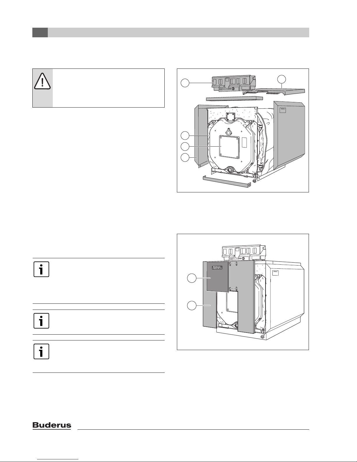
The main components of the Logano G315 oil/gas-fired
boiler are:
• Boiler block (Æ Fig. 1, [3])
The boiler block transfers the heat generated by the
burner to the boiler water.
• Boiler shell (jacket Æ Fig 1 and 2, [1]), thermal
insulation (Æ Fig 1, [2])
The boiler jacket and thermal insulation minimize
energy loss.
• Control panel (Æ Fig 1, [4])
The control panel is designed to monitor and control all
electrical components of the oil/gas-fired boiler
Logano G315.
4
2
3
1
Fig. 1 Oil/gas-fired boiler Logano G315
1 Boiler shell (jacket)
2 Thermal insulation
3 Boiler heat exchanger
4 Control Panel Assembly
1
6 720 642 622-01.1o
Observe all standards and guidelines
applicable to the installation and operation of
the system in your country.
Please observe the information on the boiler
rating plate. These are definitive and must be
observed.
To prevent boiler contamination, we
recommend installing a dirt trap in the water
system.
As a basic rule, flush existing systems before
connecting the boiler.
Install a desludging unit in the boiler return to
prevent damage to the boiler.
1
1
6 720 642 622-02.1o
Fig. 2 Front jacket
1 Boiler shell (jacket)
6
Logano G315 - Subject to technical modifications

Logano G315
Remarks
Heating oil Liquid propane (LPG) Natural Gas (NG)
The Logano G315 boiler can be operated with the specified fuels. Select a burner suitable for use with the
fuels specified for the Logano G315 boiler.
The output figures shown in the Table “Technical Data” are nominal power figures.
Carry out maintenance and cleaning procedures annually. Check that the entire system is functioning
correctly.
Immediately remedy faults.
If heating oil is used, shorter maintenance intervals may be necessary depending on the operating time.
Tab. 2
2.1 Designated use
The Logano G315 oil/gas-fired boilers have been
designed for the heating of water.
The Logano G315 can be operated with oil, gas, and
combination burners. For a list of the approved burners,
please contact Bosch Thermotechnology Corp.
This boiler can be operated with an aquastat, the
Logamatic 4000, and other control systems.
Fuels
Product description
2
Logano G315 - Subject to technical modifications
7
2
Product description
2.2 Operating conditions
Thermostream technology is a unique feature of Buderus
cast iron boilers. Return water is preheated and mixed
within the boiler before it comes in contact with the
heating surface of the combustion chamber. The
Thermostream technology ensures there is an even
temperature distribution in the boiler and avoids
condensate forming within the combustion chamber. This
unique feature reduces thermal stress, the main cause of
Minimum flow rate none
Minimum return temperature °F ( °C) none
Minimum operating temperature oil boiler
Minimum operating temperature gas boiler
Maximum supply temperature °F ( °C) 2123)/2484) (1003)/1204))
Maximum operating pressure PSI (bar) 87–(6)
For operation with two-stage oil and gas burners – Set the partial load stage to 60 %
Time constant of the temperature controller sec 40
Time constant of the monitor/limiter sec 40
1)
1)
°F ( °C) 122–(50)
°F ( °C) 122–(50)
failure of traditional cast iron boilers. The advantage of this
technology is the maintenance of the minimum operating
temperature of the boiler (Æ Tab. 3); this makes the
installation of a shunt pump unnecessary. This way, the
costs for the pump itself and its power consumption, as
well as possible failure costs are saved. The minimum
boiler operating temperature as shown in the table below
must be reached within 10 minutes and then be
maintained while the burner is running.
Control of all heating
zones with Buderus 4000
2)
External controls (BMS) or
Aquastat control
140–(60)
Tab. 3
1) This temperature has to be reached within ten minutes of the burner starting and has to be maintained whilst the burner is firing.
2) 65 °C with partial load < 60 %
3) The maximum supply temperature is 212 °F (100 °C), if the boiler is operated as hot water boiler.
4) The maximum supply temperature is 248 °F (120 °C), if the boiler is operated as a hot water generator.
2)
A heating zone with a mixing valve improves
controllability and is specifically
recommended for systems with differing
water temperature zones.
This operating condition can be easily achieved by the
controls monitoring the boiler temperature and reducing
the flow rate through the boiler until the required
temperature is reached. This is then maintained by
continuing to control flow based on the boiler water
temperature. The controls can reduce the flow rate by
closing the valves on the mixed heating circuits,
modulating the boiler primary pumps, closing the
motorized butterfly valves or by having a motorized valve
in the boiler return on a single boiler installation. The
Buderus 4000 series controls can manage this process
or it can be completed by the BMS.
If it is not possible for the control panel to regulate the
flow sufficiently to meet this operating condition, then a
shunt pump circuit must be fitted to avoid the type of
thermal stress that all boilers would experience in these
conditions. This shunt pump circuit can be controlled
either with a Buderus 4000 control panel or with a thirdparty controller. Failure to ensure that the operating
condition is maintained may lead to thermal stress in the
boiler and eventual failure of the sections which would be
outside the scope of the warranty.
8
Logano G315 - Subject to technical modifications

2.3 Compliance with standards and
regulations
Installation and operation of the system must comply with
all applicable codes, regulations and statutory
requirements.
Installation, connection of the fuel supply and flue
connector, commissioning, connection of the electrical
power supply, servicing and repair may only be carried out
by a trained or certified heating contractor. Only
registered gas fitters may carry out work on the gas train.
The system must be cleaned and serviced once a year.
The operation of the complete system must be tested at
the same time. Any faults must be corrected immediately.
The design and mode of operation of this boiler must
comply with the American National Standard ANSI
Z21.13/CSA4.9, latest edition for Gas Fired Low
Pressure Steam and Hot Water Boilers.
Other confirmed approvals and certifications are
indicated by labels on the boiler.
The heat exchanger has been designed and certified in
accordance with the ASME Boiler and Vessel Code,
Section IV.
Installation of the boiler must comply with all applicable
codes and regulations imposed by the national, Federal or
local authorities and bodies. If no specific requirements
are defined, in the USA, the latest edition of the National
Fuel Gas Code ANSI Z223.1/NFPA 54 applies. In
Canada, installation must comply in all respects with the
latest edition of the Installation Code for Gas Burning
Appliances and Equipment, CAN/CSA-B.149 and the
applicable local regulations and requirements for the
appliance category. The relevant authorities and
regulatory bodies must be informed before installation
starts.
Where required by local regulations, the system must
comply with the American Society of Mechanical
Engineers Safety Code for Controls and Safety Devices
for Automatically Fired Boilers (ASME CSD-1).
The hot water distribution system must comply with all
applicable codes and regulations. When replacing an
existing boiler, it is important to check the condition of the
entire hot water distribution system to ensure safe
operation.
In the Commonwealth of Massachusetts, this appliance
must be installed by a licensed plumber and gas fitter.
Valves external to the boiler must be fitted with T-handles
and condensate piping must be installed in accordance
with the State Plumbing Code.
Product description
2
Logano G315 - Subject to technical modifications
9

2
Product description
2.4 Additional regulations for
installations in the Commonwealth
of Massachusetts
(a) For all side wall horizontally vented gas fueled
equipment installed in every dwelling, building or structure
used in whole or in part for residential purposes, including
those owned or operated by the Commonwealth and
where the side wall exhaust vent termination is less than
seven (7) feet above finished grade in the area of the
venting, including but not limited to decks and porches,
the following requirements shall be satisfied:
• INSTALLATION OF CARBON MONOXIDE
DETECTORS. At the time of installation of the side wall
horizontal vented gas fueled equipment, the installing
plumber or gasfitter shall observe that a hard wired
carbon monoxide detector with an alarm and battery
back-up is installed on the floor level where the gas
equipment is to be installed. In addition, the installing
plumber or gasfitter shall observe that a battery
operated or hard wired carbon monoxide detector with
an alarm is installed on each additional level of the
dwelling, building or structure served by the side wall
horizontal vented gas fueled equipment. It shall be the
responsibility of the property owner to secure the
services of qualified licensed professionals for the
installation of hard wired carbon monoxide detectors.
– In the event that the side wall horizontally vented gas
fueled equipment is installed in a crawl space or an
attic, the hard wired carbon monoxide detector with
alarm and battery back-up may be installed on the
next adjacent floor level.
– In the event that the requirements of this subdivision
cannot be met at the time of completion of
installation, the owner shall have a period of thirty
(30) days to comply with the above requirements;
provided, however, that during said thirty (30) day
period, a battery operated carbon monoxide
detector with an alarm shall be installed.
• APPROVED CARBON MONOXIDE DETECTORS.
Each carbon monoxide detector as required in
accordance with the above provisions shall comply
with NPA 720 and be ANSI/UL 2034 listed and IAS
certified.
• SIGNAGE. A metal or plastic identification plate shall
be permanently mounted to the exterior of the building
at a minimum height of eight (8) feet above grade
directly in line with the exhaust vent terminal for the
horizontally vented gas fueled heating appliance or
equipment. The sign shall read, in print size no less than
one-half (½) inch in size, “GAS VENT DIRECTLY
BELOW. KEEP CLEAR OF ALL OBSTRUCTIONS”.
• INSPECTION. The state or local gas inspector of the
side wall horizontally vented gas fueled equipment shall
not approve the installation unless, upon inspections,
the inspector observes carbon monoxide detectors
and signage installed in accordance with the
provisions of 248 CRM 5.08(2)(a) 1 through 4.
(b) EXEMPTIONS: The following equipment is exempt
from 248 CRM 5.08(2)(a) 1 through 4:
• The equipment listed in Section 10 entitled
“Equipment Not Required To Be Vented” in the most
current edition of NFPA 54 as adopted by the board;
and
• Product Approved side wall horizontally vented gas
fueled equipment installed in a room or structure
separate from the dwelling, building or structure used
in whole or in part for residential purposes.
(c) MANUFACTURERS REQUIREMENTS - GAS
EQUIPMENT VENTING SYSTEM REQUIRED. When the
manufacturer of Product Approved side wall horizontally
mounted gas equipment provides a venting system
design or venting system components with the
equipment, the instructions provided by the manufacturer
for the installation of the equipment and venting shall
include:
• Detailed instructions for the installation of the venting
system or the venting system components; and
• A complete parts list for the venting system design or
venting system.
(d) MANUFACTURERS REQUIREMENTS - GAS
EQUIPMENT VENTING SYSTEM NOT PROVIDED.
When the manufacturer of Product Approved side wall
horizontally vented gas fueled equipment does not
provide the parts for the venting of flue gases, but
identifies “special venting systems”, the following
requirements shall be satisfied by the manufacturer:
• The referenced “special venting systems” shall be
included with the appliance or equipment installation
instructions; and
• The “special venting systems” shall be Product
Approved by the Board, and the instructions for that
system shall include a parts list and detailed installation
instructions.
(e) A copy of all instructions for all Product Approved side
wall horizontally vented gas fueled equipment, all venting
instructions, all parts lists for venting instructions, and/or
venting design instructions shall remain with the
appliance or equipment at the completion of the
installation.
10
Logano G315 - Subject to technical modifications
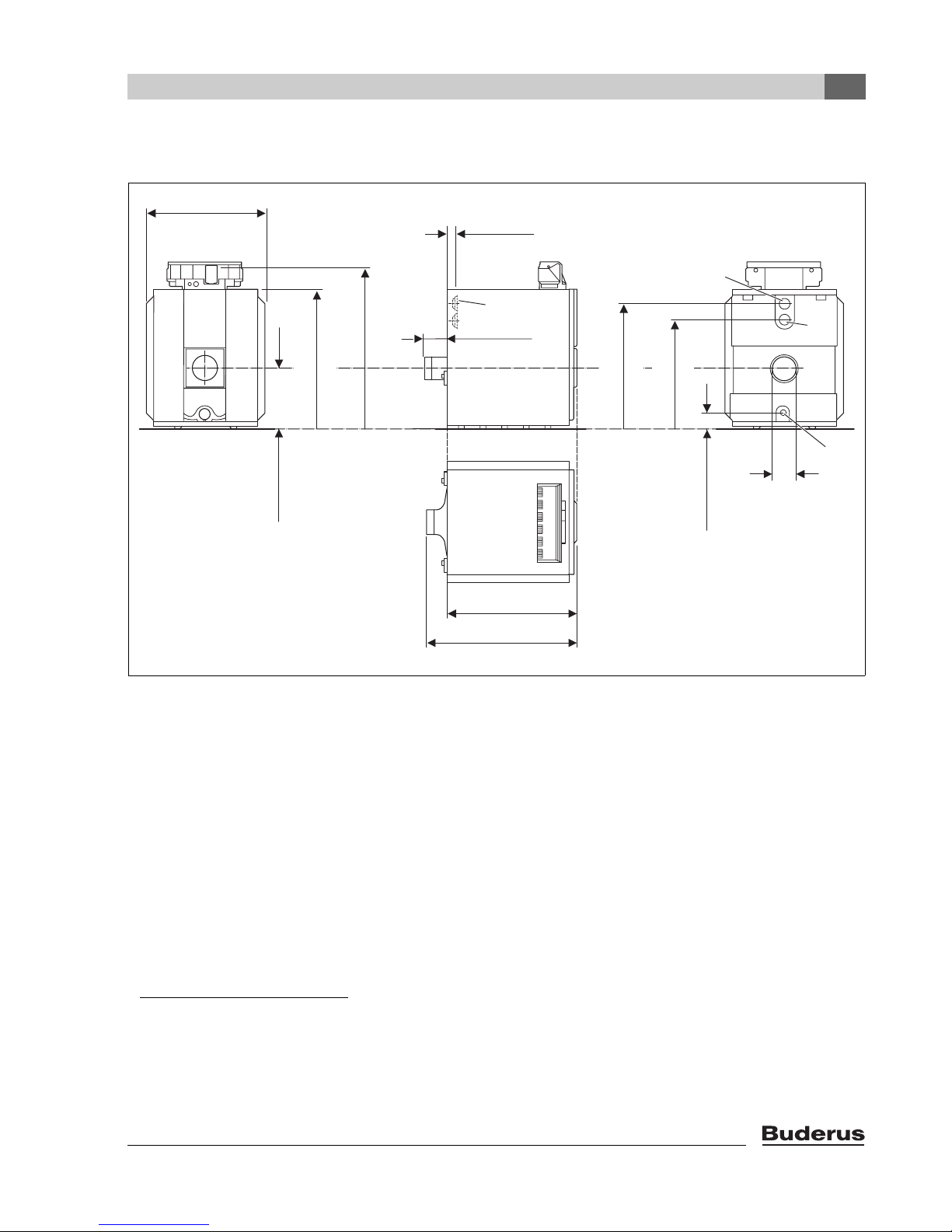
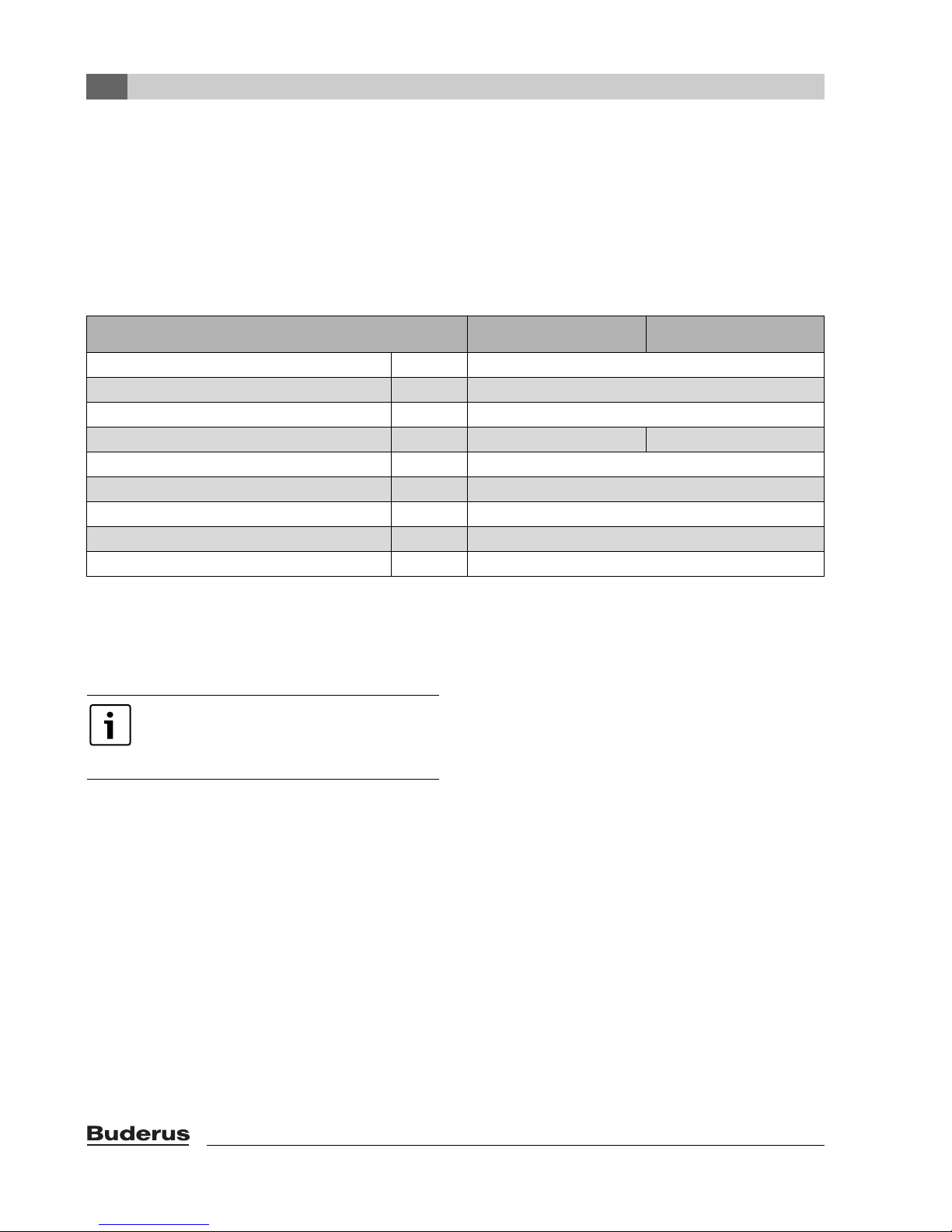
3 Specifications
34-41/64"
34 41/64"
(880 mm)
40 3/4"
40-3/4"
17-23/32"
17 23/32"
(450 mm)
47 3/64"
47-3/64"
(1195 mm)
(1035 mm)
2-13/64"
2 13/64"
(56 mm)
VK
6 7/64"
(155 mm)
36 59/64"
(938 mm)
36-59/64"
32-13/64"
Specifications
VK
32 13/64"
(818 mm)
4 11/64"
4-11/64"
(180 mm)
(106 mm)
3
RK
EL
7"
L
K
L
Fig. 3 Technical data for Logano G315 (dimensions in inches (mm))
EL Drain valve (Rp ¾)
LKBoiler heat exchanger length
L Overall boiler length
RK Return connection on the boiler
VK Supply connection on the boiler
1) With the drain valve (EL), you may only drain the system, not fill it.
2) The filling of the boiler and the system must be undertaken on a
separate connector on the return line.
3) The flange corresponds to the order reduced to 212 (DN100),
176 (DN80) or 149 (DN65).
1)
2)
3)
6 720 642 621-48.1o
Logano G315 - Subject to technical modifications
11
3
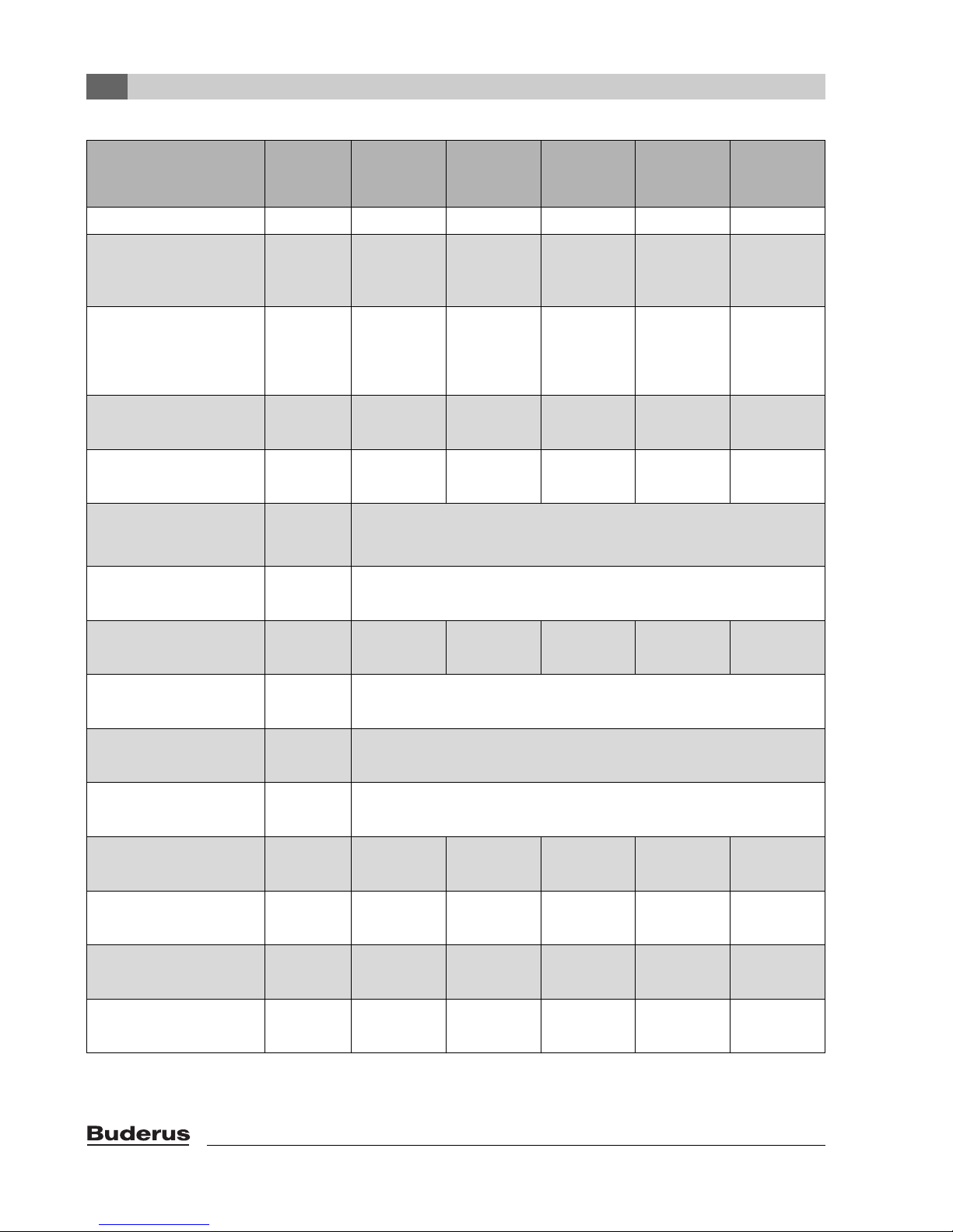
Specifications
Logano G315
Boiler capacity Unit 105 140 170 200 230
Number of boiler sections – 5 6 7 8 9
Nominal output Btu/hr
(kW )
Combustion output Btu/hr
(kW)
Boiler overall length (L) inches
(mm)
Boiler block length (L
) inches
K
(mm)
Fitting clearance, boiler
section
(width × height × depth)
Fitting clearance, boiler block
(width × height × length)
inches
(mm)
inches
(mm)
Combustion chamber length inches
(mm)
Combustion chamber
diameter
inches
(mm)
293.500 –
358.000
(86 – 105)
314.300 –
387.300
(92.1 –
113.5)
44-19/64
(1125)
38-3/16
(970)
31-7/64
(790)
362.000 –
477.800
(106 – 140)
387.300 –
516.700
(113.5 –
151.4)
50-19/32
(1285)
44-31/64
(1130)
481.000 –
580.200
(141 – 170)
515.300 –
625.900
(151.0 –
183.4)
56-57/64
(1445)
50-25/32
(1290)
28-1/32 × 36-25/32 × 6-19/64
(712 × 934 × 160)
28-1/32 × 39-1/8 × L
(712 × 994 × LK)
37-13/32
(950)
43-45/64
(1110)
15 3/4
(400)
583.600 –
682.600
(171 – 200)
624.900 –
734.100
(183.1 –
215.1)
63-3/16
(1605)
57-3/32
(1450)
K
50
(1270)
686.000 –
784.990
(201 – 230)
734.400 –
846.000
(215.2 –
247.9)
69-31/64
(1765)
63-25/64
(1610)
56-19/64
(1430)
Burner door thickness inches
(mm)
Vent connection diameter inches
(mm)
Weight, net
1)
Boiler water content gal.
Gas capacity gal.
Flue gas temperature,
partial load (60 %)
(°C)
Tab. 4
12
lb.
(kg)
(l)
(l)
°F
1.20
(543)
37.75
143
38.83
147
178.6
(137)
1.395
(631)
45.25
171
47.82
181
280.4
(138)
4-59/64
(125)
7"
(178)
1.59
(719)
52.5
199
56.8
215
176.8
(136)
1.78
(807)
60
227
65.78
249
269.6
(132)
1.975
(895)
67.5
255
69.48
263
285.8
(141)
Logano G315 - Subject to technical modifications
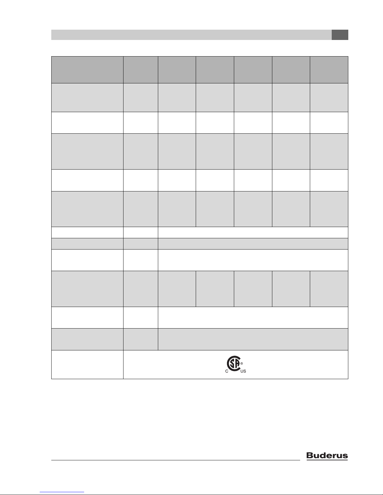
Specifications
Logano G315
Boiler capacity Unit 105 140 170 200 230
3
Flue gas temperature,
full load
°F
(°C)
323.6 – 365
(162 – 185)
309.2 –
359.6
321.8 – 356
(161 – 180)
(154 – 182)
Flue gas mass flow rate, oil,
partial load (60 %)
Flue gas mass flow rate oil,
2)
full load
Flue gas mass flow rate, gas,
partial load (60%)
Flue gas mass flow, gas,
2)
full load
CO
content, oil % 13.0
2
lb./s
(kg/s)
lb./s
(kg/s)
lb./s
(kg/s)
lb./s
(kg/s)
0.0624
(0.0283)
0.0862 –
0.1063
(0.0391 –
0.0482)
0.0626
(0.0284)
0.0864 –
0.1067
(0.0392 –
0.0484)
0.0831
(0.0377)
0.1063 –
0.1418
(0.0482 –
0.0643)
0.0836
(0.0379)
0.1067 –
0.1422
(0.0484 –
0.0645)
0.101
(0.0458)
0.1413 –
0.1717
(0.0641 –
0.0779)
0.1014
(0.0460)
0.1418 –
0.1722
(0.0643 –
0.0781)
CO2 content, gas % 10
Required draft PSI
(Pa)
(0)
316.4 –
348.8
334.4 – 374
(168 – 190)
(158 – 176)
0.1188
(0.0539)
0.1713 –
0.2013
(0.0777 –
0.0913)
0.1193
(0.0541)
0.172 –
0.2019
(0.0780 –
0.0916)
0.1367
(0.0620)
0.2013 –
0.2319
(0.0913 –
0.1052)
0.1371
(0.0622)
0.2022 –
0.2328
(0.0917 –
0.1056)
0
Fireside pressure drop in. W.C.
(mbar)
Maximum permissible supply
temperature
3)
Maximum permissible
operating pressure
°F
(°C)
PSI
(bar)
0.112 –
0.165
(0.28 – 0.41)
0.185 –
0.317
(0.46 –
0.79)
0.285 –
0.522
(0.71 –
1.30)
248
(120)
87
(6)
0.538 –
0.715
(1.34 –
1.78)
Tab. 4
1) Weight with packaging approx. 6 – 8 % higher.
2) The details relate to the upper and lower rated output range.
3) Safety limit (high limit safety cut-out). Maximum possible supply temperature = safety limit (STB) – 32 °F ( – 18 K).
Example: Safety limit (STB) = 212 °F (100 °C), max. possible supply temperature = 212 – 32 = 180 °F (100 – 18 = 82 °C).
0.530 –
0.711
(1.32 –
1.77)
Logano G315 - Subject to technical modifications
13
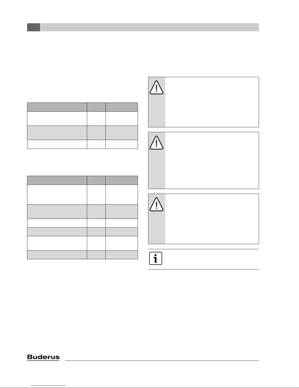
4
Scope of delivery
4 Scope of delivery
The Logano G315 can be delivered either as a preassembled block or in loose sections.
B Check that the packaging is undamaged on delivery.
B Check that the delivery is complete.
4.1 Logano G315 - delivery as a
pre-assembled block
Component Qty Packaging
Boiler block with burner door
and supply pipe
Jacket pack (according to boiler
rating)
Thermal insulation 1 bag
Tab. 5
4.2 Logano G315 – delivery
unassembled
Component Qty Packaging
Front and rear section,
3 intermediate sections as well
as burner door
Intermediate sections –
(depending on boiler size)
Fittings and draft diverter 1 Box
Tie rods and supply pipe 1 Bundle
Jacket pack (according to boiler
rating)
Thermal insulation 1 Bag
Tab. 6
1 Pallet
1 Cartons
1 Pallet
1 Pallet
1Cartons
5 Transporting the boiler
Use suitable equipment to transport the individual boiler
sections (delivery unassembled) and other individual
parts.
WARNING: Risk of injury from improperly
secured boiler sections.
B Use only suitable means of transportation
when handling the boiler sections, e.g. a
heavy duty hand truck.
B Secure the individual boiler sections to
prevent them from sliding off during
transport.
NOTICE: Risk of system damage from
impacts.
B The standard delivery of the Logano G315
oil/gas-fired boiler contains components
that are sensitive to shock.
B During handling protect all electronic and
other components against impact.
B Please observe the transport instructions
on the packaging.
NOTICE: Risk of system damage from
contamination.
B If you intend to keep the boiler in storage
once it has been assembled, observe the
following:
B Protect the boiler connections against
contamination by sealing them off or
covering them.
Dispose of packaging in an environmentally
responsible manner.
14
Logano G315 - Subject to technical modifications
6 Positioning the boiler
Positioning the boiler
6
This chapter describes how to properly position the
Logano G315.
NOTICE: Risk of system damage from
freezing.
B Install the system in a room free from the
danger of freezing.
6.1 Tools and auxiliary materials
The following tools and auxiliary materials are required for
the boiler assembly (the listed items must be provided by
the installer):
• Boiler assembly tool 2.3 (Æ Fig. 4)
• Installation kit (accessory)
• Steel hammer and wooden or rubber mallet
• Half-round bastard file
• Screwdriver (Philips and flat head)
• Flat chisel
• Metric wrenches
• Support wedge, flat iron
• Cleaning rags and cloth
• Fine emery cloth
•Wire brush
•3-in-1 oil
• Solvent (gasoline, mineral spirits)
• Spirit level, tape measure, chalk, straight edge
• Blanking flange with vent facility (for pressure test)
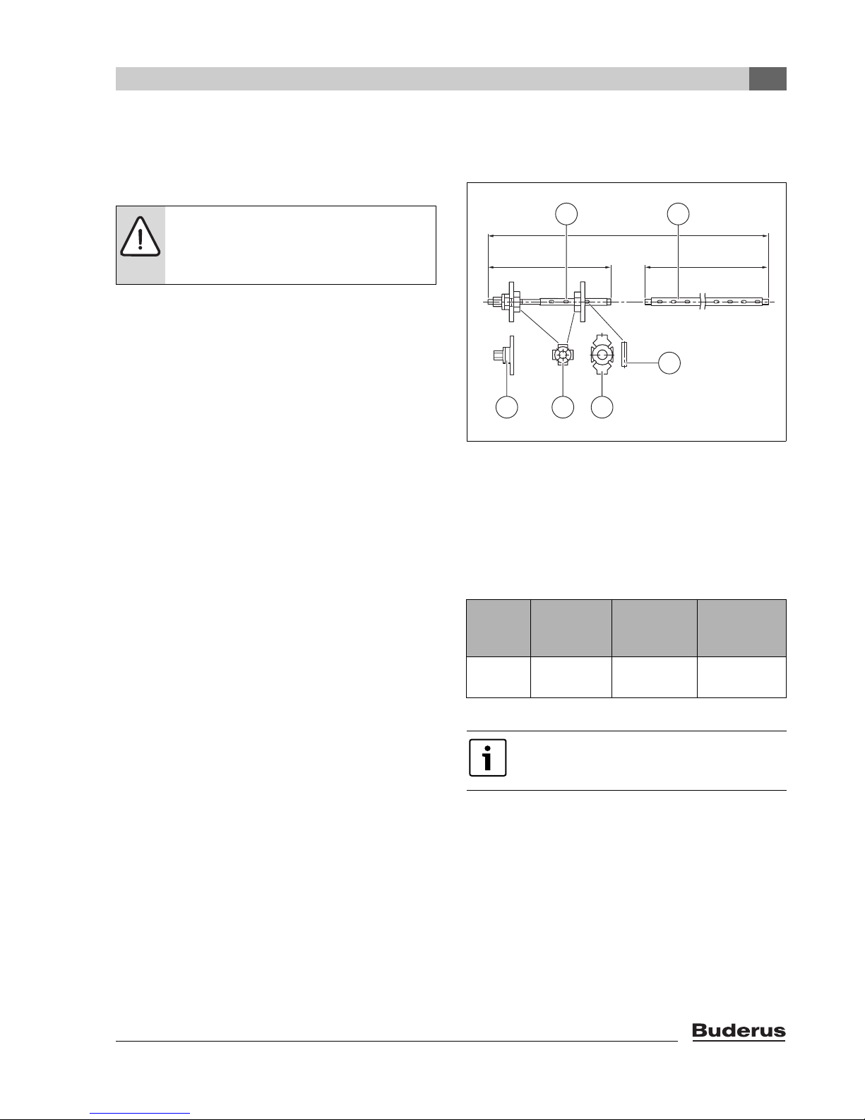
6.1.1 Boiler assembly tool size 2.3
4 5
L
2
L
1
L
2
6
3 2 1
Fig. 4 Boiler assembly tool size 2.3
1 Mating flange
2 Additional flange
3 Compression unit (pressure flange with clamping nut)
4 Tie rod
5 Extension
6 Wedge (size 2.3)
121-1/4" (3080 mm)
L
1
31-1/2" (800 mm)
L
2
Boiler
sections
Assembly
tool(s) per
boiler hub
Extension
piece per
boiler hub
6 720 642 623-03.1o
Length (total)
in inches
(mm)
Logano G315 - Subject to technical modifications
5 – 9 1 3
Tab. 7
For the correct arrangement of the flange
when performing the assembly procedure,
refer to page 22.
121-1/4
(3080 mm)
15
6
Positioning the boiler
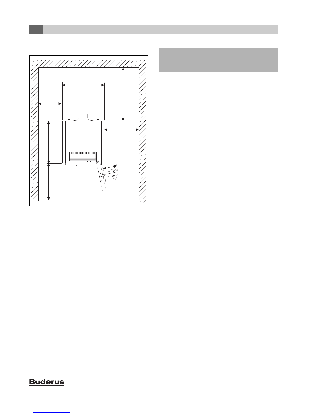
6.2 Recommended wall clearances
34-41/64"
34 41/64"
15-3/4"
≥ 15 3/4"
(400 mm)
(880 mm)
29 1/2"
29-1/2"
AB + 4"
(~ 750 mm)
Boiler capacity Clearance A in inches (mm)
Boiler
MBH (kW)
358 – 686
(105 – 230)
sections
5 – 9 59 (1500) 39-3/8 (1000)
Recommended Minimum
Tab. 8
If you do not observe the recommended minimum
clearance (Æ Fig. 5), you will not be able to use the
cleaning kit (accessory). Alternatively shorter cleaning
devices or wet cleaning may be used.
K
L
(AB+100 mm)
AB
A
6 720 642 621-02.1o
Fig. 5 Installation room with boiler
Observe the recommended wall clearances for complete
opening of the burner door, for boiler installation and for
cleaning and maintenance Fig. 5.
The burner door can be hung with the hinges on the right
or left.
When installing your boiler maintain the recommended
minimum dimensions. Select the recommended
clearances between wall and boiler for easy access for
installation, maintenance and service work.
The wall clearance on the hinge side must be at least the
burner projection (AB). A distance of AB +4 inches
(AB + 100 mm) from the wall is recommended.
The length L
or boiler rating Æ Spare parts, page 51.
depends on the number of boiler sections
K
16
Logano G315 - Subject to technical modifications
Positioning the boiler
6
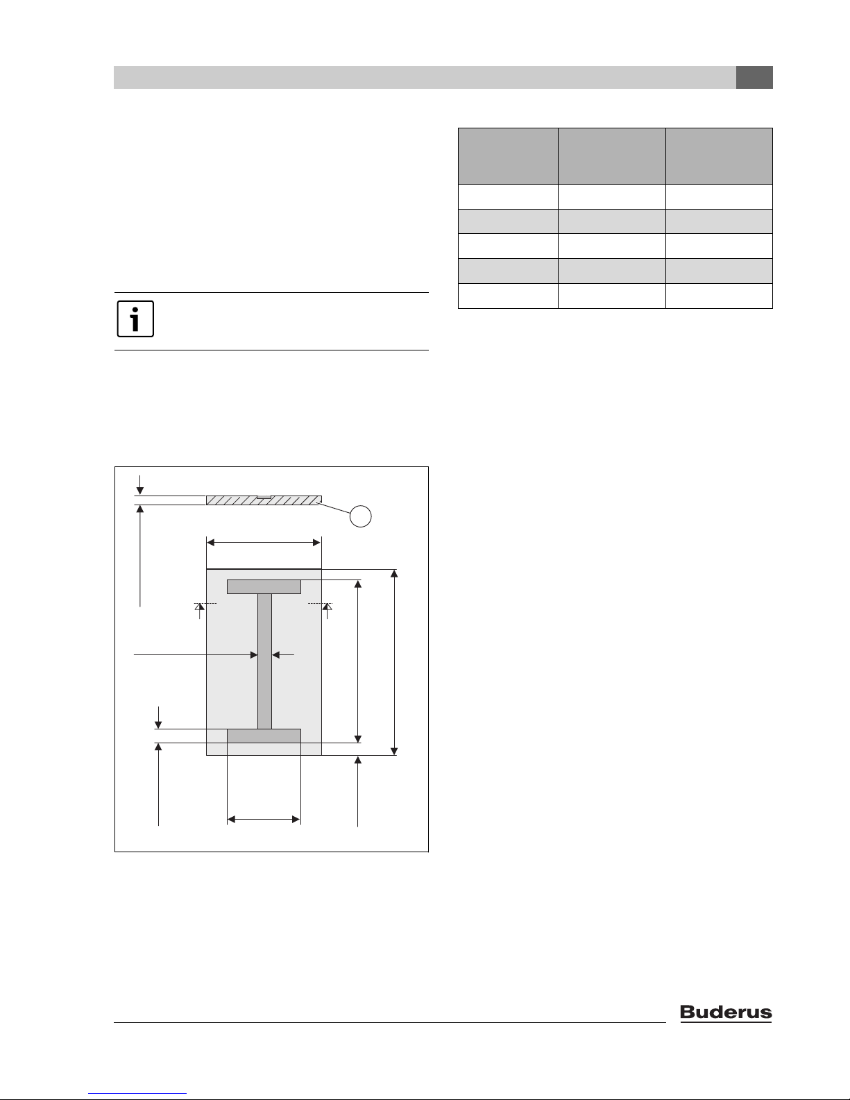
6.3 Installing the boiler on a boiler base
or foundation
When setting up the boiler, we recommend you observe
the specified wall clearances for improved installation and
maintenance (Fig. 5).
It is advisable to place the boiler on a 2 – 4 inch
(50 – 80 mm) tall base (Fig. 6, [1]). The base should be
completely flat and level. The front edge of the boiler
should be flush with the edge of the base.
A silencing boiler base is available as
optional equipment from Buderus.
If this optional boiler base is not used, a concrete
foundation can be constructed on-site. When building the
foundation, a 3 15/16 x 1 31/32 x 5/16 inches
(100 x 50 x 8 mm) steel angle or 3 15/16 x 13/64 inches
(100 x 5 mm) steel flat should be incorporated (Æ Fig. 6
and Tab. 9).
1
2...4"
34-3/4"
34 3/4"
(~ 880 mm)
L1
Number of
boiler sections
5 38-3/16 (970) 28-3/4 (730)
6 44-31/64 (1130) 35-1/32 (890)
7 50-25/32 (1290) 41-21/64 (1050)
8 57-3/32 (1450) 47-41/64 (1210)
9 63-25/64 (1610) 53-15/16 (1370)
(base)
in inch (mm)
L2
(steel section)
in inch (mm)
Tab. 9 Foundation dimensions and lengths of steel flats
or steel angles
(~ 50...80 mm)
4"
(100 mm)
4"
(100 mm)
21 1/4"
(540 mm)
Fig. 6 Base dimensions
2
L
3-/2"
3 1/2"
(~ 90 mm)
6 720 642 621-01.1o
1
L
Logano G315 - Subject to technical modifications
17
7
Boiler block assembly
7 Boiler block assembly
WARNING: Risk of injury from improperly
secured boiler sections.
B Use only suitable means of transportation
when handling the boiler sections, e.g.
a heavy duty hand truck. When handling,
secure the boiler sections to the means of
transport to prevent them slipping.
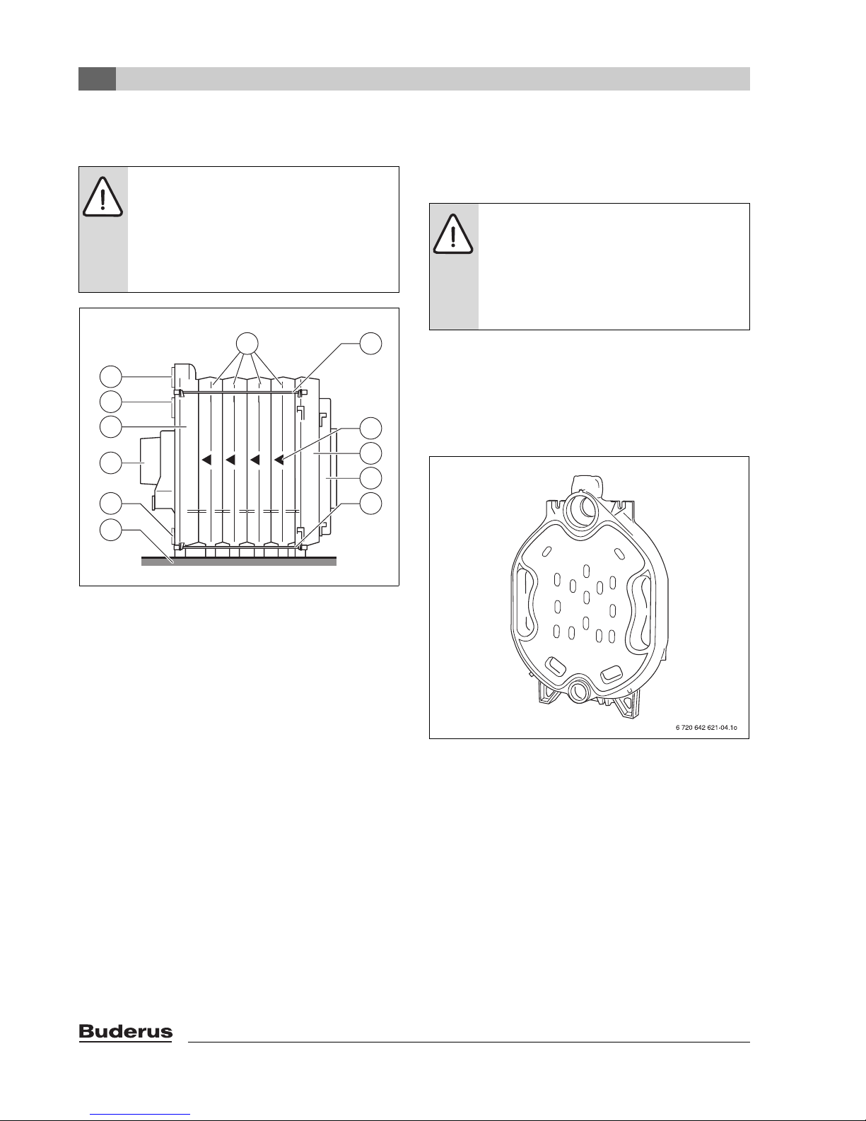
87
6
5
4
3
9
10
11
2
8
1
6 720 642 621-03.1o
Fig. 7 Boiler heat exchanger
Key to Fig. 7:
1 Boiler base or foundation
2 Draining
3 Exhaust Manifold
4 Rear section
5 Return connection
6 Supply connection
7 Intermediate sections
8 Tie rod
9 Directional arrow
10 Front section
11 Burner door with burner plate
Depending on the type of delivery, we distinguish
between delivery unassembled and as a ready
assembled block. When delivered as a readyassembled block, the boiler is assembled and checked for
leaks prior to despatch. If, because of physical limitations,
a boiler block cannot be assembled as a complete unit,
delivery unassembled would enable assembly on site.
For details of assembling the remainder of the
boiler if the heat exchanger is delivered preassembled, see Æ Chapter 7.3, page 23.
7.1 Assembly of a boiler block from
sections
WARNING: Risk of injury from inadequately
secured boiler sections.
B Secure boiler sections during assembly
and take measures to prevent them from
tipping over. If a hoisting tool is available,
this can be used to set up the boiler
sections safely.
The boiler block is always installed starting from the rear
with the rear section (Fig. 7, [4]) and working towards the
front. The front section (Fig. 7, [10]) is always fitted last.
Observe the directional arrows (Fig. 7, [9]) during
assembly and carry this out in accordance with the
following instructions and illustrations.
Fig. 8 Rear section
18
Logano G315 - Subject to technical modifications
Boiler block assembly
7
7.2 Joining the boiler block assembly
(delivery unassembled)
Remove nuts and washers from the studs on the hubs of
the boiler sections before attaching the rear section and
front section.
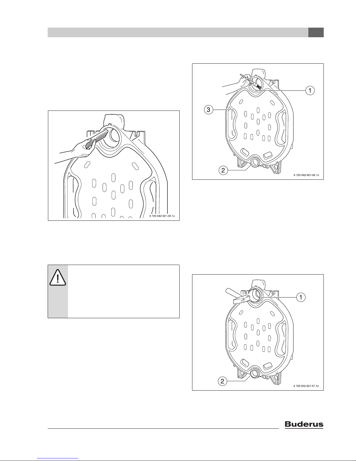
B Set up the rear section and secure it against tipping.
B File down any burrs on the hubs (Æ Fig. 9).
Fig. 9 Remove burrs
B Clean the packing grooves where required using a wire
brush and cloth (Fig. 10, [3]).
B Clean the hub sealing faces (Fig. 10, [1 and 2]) with a
rag soaked in solvents or gasoline.
WARNING: Health hazard from noxious
vapors released from material handling, such
as solvents, primers or sealant.
B Ensure adequate ventilation of the
installation area.
B Please note the handling and safety
instructions of the product used.
B Evenly coat the hub sealing faces with sealant.
Fig. 10 Preparing the packing grooves and hubs
The next step involves preparing the nipples that will
eventually seal the boiler sections.
B Clean nipple with a rag soaked in solvents or gasoline
and coat evenly with sealant.
B Insert the nipple straight into the upper (Sz. 2,119/50)
and lower (Sz. 0, 57/50) hub of the rear section and
hammer home securely with alternate heavy blows. The
upper nipple (Fig. 11, [1]) and the lower nipple
(Fig. 11, [2]) should protrude approx. 28 mm out of the
corresponding hub once they have been driven in.
B Remove any burrs with a file.
Logano G315 - Subject to technical modifications
Fig. 11 Driving nipples home
19
7
Boiler block assembly
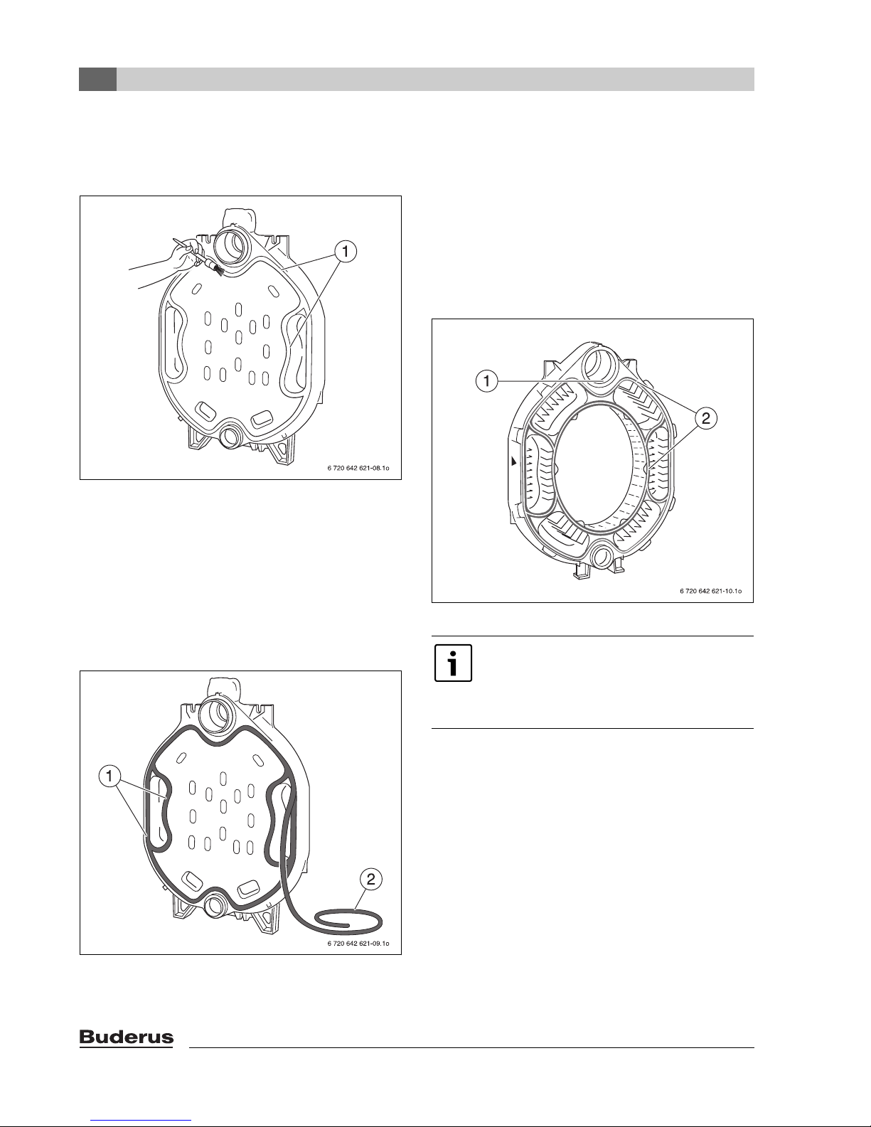
The packing grooves (Fig. 12, [1]) must be clean and dry
to enable the sealant rope to adhere properly.
B Coat the packing grooves with adhesive (primer).
Fig. 12 Coat the packing grooves with adhesive
B Insert the flexible sealant rope (Æ Fig. 13, [2]) on the
front of the rear section, starting around the upper hub,
into the packing grooves (Æ Fig. 13, [1]) and press in
lightly. At the butt joints, overlap the sealant rope by
approx. 2 cm and press firmly together.
B Unroll the required length of sealant rope from the
spool supplied.
B Peel the backing paper from the sealant rope when
inserting into the packing groove (do not stretch).
Preparation of the first intermediate section:
B File down any burrs on the hubs (as shown in Fig. 9).
B The packing springs must be clean and dry. Clean if
necessary.
B Clean the hub sealing faces with a rag soaked in
solvents or gasoline.
B Evenly coat the hub sealing faces with sealant (Fig. 14,
[1]).
B Coat the packing springs with adhesive (primer)
(Fig. 14, [2]).
Fig. 14 Preparing the centre section
To make installation easier, place the boiler
section to be fitted onto the nipple on the
upper hub first. Once this has been done, the
boiler section can be aligned with the lower
hub.
Fig. 13 Inserting sealant rope
20
Logano G315 - Subject to technical modifications
Boiler block assembly
7
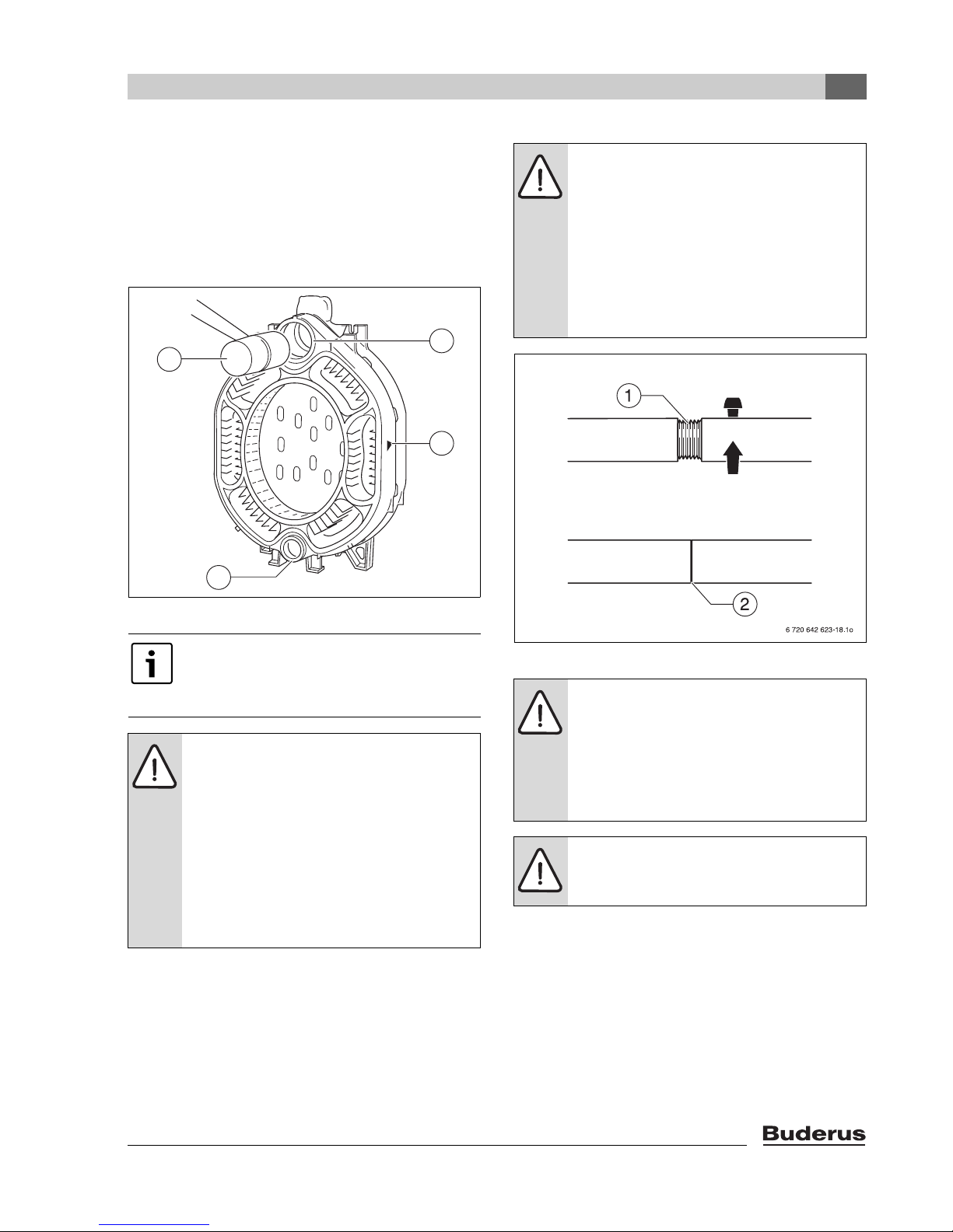
The directional arrow (Æ Fig. 15, [3]) must point in the
direction of the rear boiler section.
B Position the intermediate section so that the upper and
lower hubs (Æ Fig. 15, [2 and 4]) fit onto the nipples in
the rear section.
B Pound first intermediate section onto the rear section
using a wooden or a rubber mallet (Æ Fig. 15, [1]).
2
1
3
4
6 720 642 621-11.1o
NOTICE: Assembly tool damage due to
loose screw connections of the tie rods.
B Always check the tie rods before each use
and retighten as necessary. The tie rod is
correctly positioned if it is fully inserted
and no threads are showing (Æ Fig. 16,
[2]).
B Always keep the threads (Æ Fig. 16, [1])
clean. Dirty threads may damage the
assembly tool during compression.
Fig. 15 Pound intermediate section in place
Before the nipples are inserted in the next
intermediate section, the part-assembled
boiler block must be compressed using the
boiler assembly tool.
NOTICE: The boiler can be damaged by
pulling the boiler sections together
incorrectly or due to excessive compression.
B Ensure that the nipples are positioned
straight in the boiler hubs after being
pounded in and that they have not been
compromised.
B Never compress more than one nipple
joint at a time.
B Stop compressing the sections when the
boiler hubs meet.
Fig. 16 Boiler assembly tool 2.3
CAUTION: Danger of accident from material
fatigue. Improperly used or poorly maintained
assembly tools may fail.
B Never work directly in front of the
assembly tool while it is being tensioned.
B Ensure that no one is standing in front of
the assembly tool.
NOTICE:
B Only boiler assembly tools size 2.3 may be
used (Fig. 4, page 15 and Fig. 17, [1 and 2]).
Logano G315 - Subject to technical modifications
21
 Loading...