

Page 1
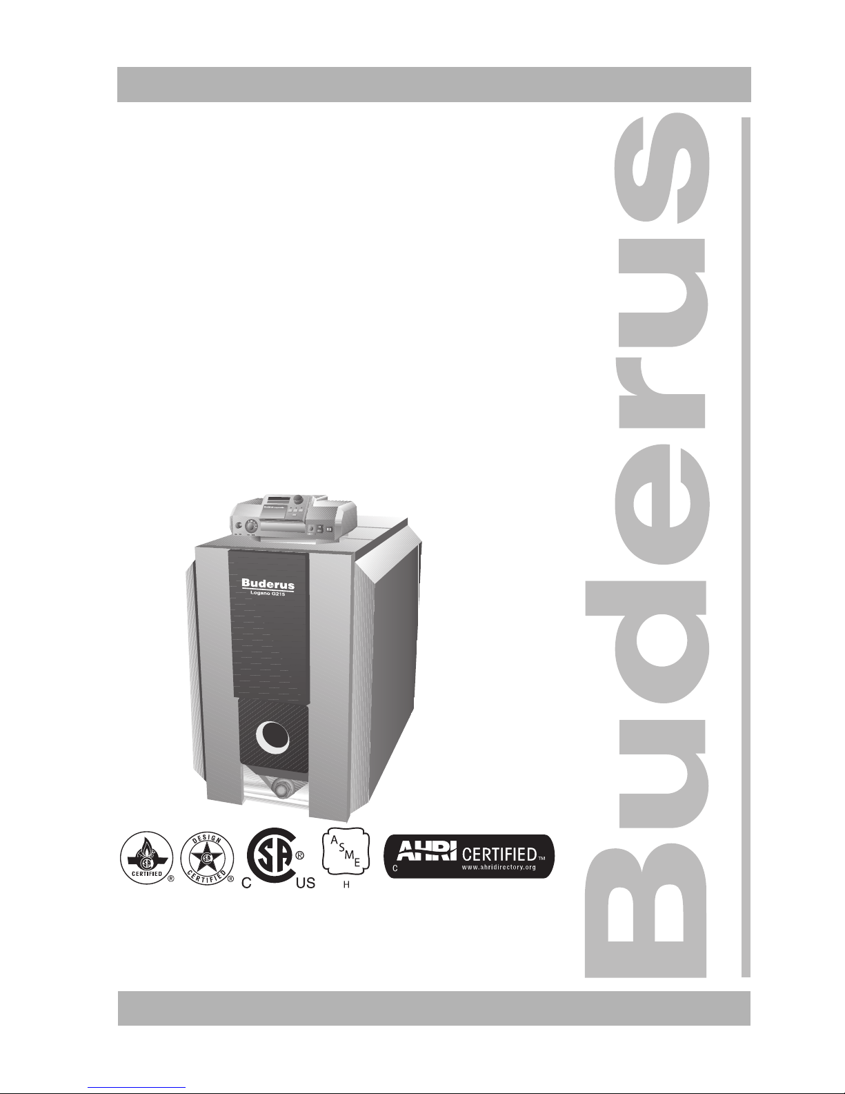
Please read these instructions carefully
6 720 804 877 – 2012/08 EN-US For the owner/operator
Users Manual
Oil and Gas Fired Boiler
Logano G215 US
C
Page 2

2
We reserve the right to make any changes due to technical modifications!
Users Manual Logano G215 US • Issue 08/2004
Buderus Heiztechnik GmbH • http://www.heiztechnik.buderus.de
Table of Content
1 Safety Considerations . . . . . . . . . . . . . . . . . . . . . . . . . . . . . . . . . . . . . . . . . 3
1.1 With respect to this manual . . . . . . . . . . . . . . . . . . . . . . . . . . . . . . . . . . . . . . 3
1.2 Application Purpose. . . . . . . . . . . . . . . . . . . . . . . . . . . . . . . . . . . . . . . . . . . 3
1.3 Guideline of Notice . . . . . . . . . . . . . . . . . . . . . . . . . . . . . . . . . . . . . . . . . . . 3
1.4 Observe the following symbols . . . . . . . . . . . . . . . . . . . . . . . . . . . . . . . . . . . . 3
1.4.1 What to do when you smell smoke. . . . . . . . . . . . . . . . . . . . . . . . . . . . . . . . 3
1.4.2 Boiler placement . . . . . . . . . . . . . . . . . . . . . . . . . . . . . . . . . . . . . . . . . 4
2 Product Description . . . . . . . . . . . . . . . . . . . . . . . . . . . . . . . . . . . . . . . . . . . 5
3 System Operation . . . . . . . . . . . . . . . . . . . . . . . . . . . . . . . . . . . . . . . . . . . . 6
3.1 Turning on the system . . . . . . . . . . . . . . . . . . . . . . . . . . . . . . . . . . . . . . . . . 6
3.2 Turning off the system . . . . . . . . . . . . . . . . . . . . . . . . . . . . . . . . . . . . . . . . . 6
3.3 Emergency operation . . . . . . . . . . . . . . . . . . . . . . . . . . . . . . . . . . . . . . . . . . 7
3.4 Testing system pressure: adding make-up water and venting the system . . . . . . . . . . . . 7
3.4.1 When to test system pressure? . . . . . . . . . . . . . . . . . . . . . . . . . . . . . . . . . 7
3.4.2 Testing system pressure . . . . . . . . . . . . . . . . . . . . . . . . . . . . . . . . . . . . . 7
3.4.3 Adding Make-up Water and Venting of the system . . . . . . . . . . . . . . . . . . . . . . . 7
3.5 Why is regular maintenance important? . . . . . . . . . . . . . . . . . . . . . . . . . . . . . . . 9
4 Trouble Shooting your Heating System . . . . . . . . . . . . . . . . . . . . . . . . . . . . 10
System pressure
Record fuel source:
__________________________________
Optimum operating pressure
(optimum valve):
______________ psi
Max system pressure:
(Standard = 30 psi)
______________ psi
Company/Date/Signature
Address of manufacturer:
Buderus Hydronic Systems, Inc.
50 Wentworth Avenue
Londonderry, New Hampshire 03053, USA
Telefon: (001) 603 552 1100
Fax: (001) 603 421 2719
Internet: www.buderus.net
Page 3

Safety Considerations 1
3
We reserve the right to make any changes due to technical modifications!
Users Manual Logano G215 US • Issue 08/2004
Buderus Heiztechnik GmbH • http://www.heiztechnik.buderus.de
1 Safety Considerations
1.1 With respect to this manual
This manual contains important information regarding
safe and efficient operation and maintenance of your
boiler.
The G215 boiler is designated as a heating appliance.
1.2 Application Purpose
The G215 boiler is used as a hot water heating boiler for
space heating purposes as well as DHW heating using
an indirect fired hot water tank in a closed loop heating
system for single and multi-family homes.
1.3 Guideline of Notice
Two levels of danger are identified by the following
warning labels:
Î Cross reference
A cross reference to another statement or another
manual is designated with an arrow Î .
1.4 Observe the following symbols
Learn proper operating procedures for your heating
system so that you:
– are carefully and completely instructed by your
installing contractor regarding proper operating
procedures.
– have carefully read the G215 Operating Manual.
Perform only those tasks on your heating system, as
they are described in this G215 Operating Manual.
1.4.1 What to do when you smell smoke
WARNING!
DANGER
Denotes a possibly severely dangerous
situation where, without proper caution,
bodily injury or loss of life may result.
CAUTION!
DANGER OF INJURY/SYSTEM
DAMAGE
Denotes a possibly dangerous situation
that can lead to mild or moderate bodily
injury or physical damage.
APPLICATION NOTICE
Application comment for optimum use of
equipment and adjustment as well as
useful information.
WARNING!
DANGER
due to unqualified personnel.
z Please note that the installation, start-
up and maintenance can only be
performed by a qualified heating
contractor or service organization. Any
work on electrical and fuel carrying
components must be done by a
qualified service technician.
WARNING!
DANGER TO LIFE
Explosive danger due to flammable fumes!
z No open fire! Do not smoke! Do not
use a lighter!
z Avoid generating sparks! Do not use a
electrical switch, or telephone,
electrical plug or bell!
z Shut off main gas /oil supply!
z Open windows and doors!
z Notify home owner, but do not use a
door bell or phone!
z Leave the building!
z Notify the gas utility or fuel oil service
company immediately from a remote
location.
z Possibly notify the police or fire
department.
z Immediately leave the building when
hearing or seeing discharging gases!
Page 4
4
We reserve the right to make any changes due to technical modifications!
Users Manual Logano G215 US • Issue 08/2004
Buderus Heiztechnik GmbH • http://www.heiztechnik.buderus.de
Safety Considerations1
1.4.2 Boiler placement
WARNING!
DANGER
Due to poisoning!
Insufficient combustion air for chimney
vent boilers with room air for combustion
can lead to dangerous conditions.
z Make sure that the combustion air
supply and discharge openings are not
reduced or closed off.
z Keep doors to the boiler room closed
and do not block lovers in boiler room
door.
z Protect the boiler room and avoid
rodents and birds from entering and
blocking the air openings.
z When the above issues have not been
resolved, the boiler can not be placed in
operation.
WARNING!
FIRE DANGER
due to flammable materials or liquids.
z Make sure that flammable or liquid
materials are not placed near the boiler.
Page 5

Product Description 2
5
We reserve the right to make any changes due to technical modifications!
Users Manual Logano G215 US • Issue 08/2004
Buderus Heiztechnik GmbH • http://www.heiztechnik.buderus.de
2 Product Description
The G215 boiler is a low temperature boiler for oil or gas
firing with a burner for both outdoor reset operation with
a suitable control or for cold start operation with a
Honeywell aquastat.
Your heating contractor or installer has equipped the
boiler with an approved burner.
The boiler consists of the following components:
– Logamatic control panel or Aquasmart control
– Boiler jacket
– Boiler block with insulation
– Customized burner
The control panel controls boiler temperature and
controls burner and pump operation.
The boiler can also be equipped with a Aquasmart
control for a more simple control of boiler operation.
The boiler jacket reduces energy loss and noice levels.
The boiler block transfers the heat produced by the
burning of the fuel to the boiler water. The insulation
reduces the standby loss.
Fig. 1 Boiler less burner
1 Logamatic control panel
2 Boiler jacket
3 Boiler block with insulation
4 Burner door front panel
1
2
3
4
Page 6

6
We reserve the right to make any changes due to technical modifications!
Users Manual Logano G215 US • Issue 08/2004
Buderus Heiztechnik GmbH • http://www.heiztechnik.buderus.de
System Operation3
3 System Operation
3.1 Turning on the system
Make sure prior to turning the system on:
– that the operating pressure is sufficient.
– that main fuel shut-off valve has been opened.
– that the main emergency switch is turned on.
When using a Buderus Logamatic control (Fig. 2)
z Set the adjustable aquastat dial on “AUT“ .
z Set the main switch to position "I". This turns on the
entire heating system.
When using a Aquasmart control (Fig. 3)
z Turn on the main system switch (Position "ON").
This activates the entire heating system.
3.2 Turning off the system
Buderus Logamatic Control (Fig. 2)
z Turn off main service switch (Position "0") at control.
This shuts off the boiler as well as all other system
components.
With Aquasmart control (Fig. 3)
z Turn off main service switch (Position "OFF") This
shuts off the entire system and all its components.
z Shut off main fuel supply with main fuel valve.
Fig. 2 Turning on heating system (Logamatic 2000)
1 Adjustable aquastat dial
2 Main service switch
I
0
1
2
NOTICE
Information regarding the operation of the
Logamatic control, such as setting of
temperatures etc, can be found in the
Î documentation supplied with the
control.
Fig. 3 Heating system control with Aquasmart control (main
service switch)
CAREFUL!
SYSTEM DAMAGE
due to freezing conditions.
When the system is not in operation, the
potential for a freeze-up exists.
z Keep the system in operation as much
as possible.
z Protect the system against freeze-ups
by either filling the system with a 50%
glycol solution, or by draining both the
heating and DHW systems at their
lowest points.
Page 7

System Operation 3
7
We reserve the right to make any changes due to technical modifications!
Users Manual Logano G215 US • Issue 08/2004
Buderus Heiztechnik GmbH • http://www.heiztechnik.buderus.de
3.3 Emergency operation
Proceed in the following manner in an emergency
situation, such as a fire:
z Shut off fuel supply at the main shut off valve.
z Shut off the heating system by means of the main
service switch.
3.4 Testing system pressure: adding make-up water and venting the system
3.4.1 When to test system pressure?
Newly added make-up water tends to reduce its volume
within the first few days due to elimination of entrained
air. This may lead to air build-up and possible system
noise.
z Check newly started systems daily for system
pressure and bleed radiators if necessary.
z Check system pressure on a monthly basis and add
make-up water automatically and possibly bleed the
radiators.
3.4.2 Testing system pressure
The system operating pressure must be at least 12 to
15 psi (1 bar). The specific recommended
z The specific recommended test pressure can be
found on Îpage 2. of this manual.
z Read off the pressure (psi) and temperature (°F) at
the P & T guage located at the supply side of the
boiler.
z When the system pressure drops below 12 to 15 psi,
add make-up water to the system.
3.4.3 Adding Make-up Water and Venting of the
system
Have your heating contractor or installer indicate to you
the location of the automatic feed valve and the
automatic air elimininator.
Fig. 4 Pressure/temperature gauge (located at the rear of
the boiler)
Page 8

8
We reserve the right to make any changes due to technical modifications!
Users Manual Logano G215 US • Issue 08/2004
Buderus Heiztechnik GmbH • http://www.heiztechnik.buderus.de
System Operation3
z Connect water hose to boiler drain and water supply.
z Slowly fill the boiler system. Observe water pressure
of the heating system.
z Close the water supply when reaching the desired
system pressure.
z Bleed sir from the system at radiator air vents and
other locations.
z When the system pressure drops due to air venting,
add more water to the system.
z Disconnect water hose from boiler.
Please contact your heating contractor or service
company when you are changing your heating system to
another fuel, or when you are switching over to fuel with
different specifications.
CAREFUL!
SYTEM DAMAGE
due to thermal stresses.
When the boiler is hot and cold water is
being added, this may lead to thermal
stresses and shock the boiler. This may
lead to a cracked boiler.
z Add only make-up water to the boiler
when the boiler temperature below 100
F. (Or when the cold feed is piped in on
the supply side of the boiler so that cold
make-up water is first sent into the
system).
WARNING!
SYSTEM DAMAGE
Due to frequent filling of system.
When you need to frequently add water to
the system, you can cause damage to the
system due to fresh water entry leading to
corrosion and internal lime build-up.
z Check with your local service company
or contractor if you can use regular
untreated tap water, or if the fill water
must be treated.
z Please inform your installing contractor
or service company, if frequent use of
make-up water is necessary.
CAUTION!
SYSTEM DAMAGE
due to incorrect fuel.
z Use only the designated fuel listed on
Îpage 2 of this manual.
Page 9

System Operation 3
9
We reserve the right to make any changes due to technical modifications!
Users Manual Logano G215 US • Issue 08/2004
Buderus Heiztechnik GmbH • http://www.heiztechnik.buderus.de
Boiler room
3.5 Why is regular maintenance important?
Heating systems require regular maintenance for the
following reasons:
– To maintain high efficiency operation and minimal
use of fuel.
– To maintain a high level of system reliability.
– To keep environmental emissions at a minimum.
z We recommend that you sign a yearly maintenance
agreement with your fuel oil company or service
company.
CAUTION!
BOILER DAMAGE
due to contaminated combustion air.
z Never use or store chlorine containing
cleaning agents or hydro-carbonhalogen type compounds (such as
sprays, cleaning and dissolving agents,
paints, glues and alike) in the boiler
room or near the combustion air
passages.
z Avoid excessive dust generation.
CAREFUL!
SYSTEM DAMAGE
due to water.
z In case of flooding conditions, shut of
the fuel supply and electrically
disconnect the heating system
(Î Chapter 3.2, page 6).
z Have your system fully checked by a
qualified heating contractor or service
company prior to putting it back in
operation.
z Have all components, that have been in
contact with water, replaced by your
contractor or service company.
CAREFUL!
SYSTEM DAMAGE
due to missing or poorly performed boiler
cleaning and maintenance.
z Have your heating system once
annually checked, cleaned and
serviced by a qualified service
company or contractor.
Page 10

10
We reserve the right to make any changes due to techincal modifications!
Users Manual Logano G215 US • Issue 08/2004
Buderus Heiztechnik GmbH • http://www.heiztechnik.buderus.de
Trouble Shooting your Heating System4
4 Trouble Shooting your Heating System
Two different type of problems can be identified:
– burner related problems, or
– problems related with the control system and heating
system.
An alarm light on the burner will typically light up during
a burner lock-out condition (Î See burner manual).
Typically this problem is resolved by pressing the burner
reset button. Press the burner reset button once. If the
burner does NOT fire, contact your local service
company for assistance.
Problems related to the control panel and/or heating
system itself, are typically shown on the display of the
control panel, if the boiler is so equipped. Further
information can be found in the Î manuals supplied
with the control panel.
Burner lock-out condition
z Press the burner reset button once. If the burner
does NOT fire, contact your local service company
for assistance.
Fig. 5 Burner lock-out condition
1 Burner
1
CAUTION!
SYSTEM DAMAGE
due to freezing conditions.
When the heating system is not in
operation due to a problem condition, the
possibility of a freeze-up may exist.
z Try to locate and resolve the problem.
z If not possible, contact your local con-
tractor or service company.
Page 11

11
We reserve the right to make any changes due to technical modifications!
Users Manual Logano G215 US • Issue 08/2004
Buderus Heiztechnik GmbH • http://www.heiztechnik.buderus.de
NOTICE
Page 12

Buderus Heiztechnik GmbH, 35573 Wetzlar
http://www.heiztechnik.buderus.de
E-Mail: info@heiztechnik.buderus.de
Local installer:
 Loading...