

Buderus Logano G215 US, Logano G215/3 US, Logano G215/4 US, Logano G215/5 US, Logano G215/6 US Installation And Maintenance Instructions Manual
...
Please read carefully prior to installation and maintenance
6303 1818 – 07/2005 For heating engineers
Installation and maintenance
instructions
Oil and gas-fired boilers
Logano G215 US

Table of Content
2
Installation and maintenance instructions Logano G215 US oil/gas-fired boilers • Issue 11/2004
We reserve the right to make any changes due to technical modifications.
1 Safety Considerations . . . . . . . . . . . . . . . . . . . . . . . . . . . . . . . . . . . . . . . . . 4
1.1 With respect to this manual . . . . . . . . . . . . . . . . . . . . . . . . . . . . . . . . . . . . . . 4
1.2 Application Purpose. . . . . . . . . . . . . . . . . . . . . . . . . . . . . . . . . . . . . . . . . . . 4
1.3 Guideline of Notice . . . . . . . . . . . . . . . . . . . . . . . . . . . . . . . . . . . . . . . . . . . 4
1.4 Please observe these notes . . . . . . . . . . . . . . . . . . . . . . . . . . . . . . . . . . . . . . 4
1.4.1 If you notice a smell of gas . . . . . . . . . . . . . . . . . . . . . . . . . . . . . . . . . . . . 4
1.4.2 Installation tips . . . . . . . . . . . . . . . . . . . . . . . . . . . . . . . . . . . . . . . . . . 4
1.4.3 Tips for the boiler room. . . . . . . . . . . . . . . . . . . . . . . . . . . . . . . . . . . . . . 5
1.5 Tools, materials and equipment . . . . . . . . . . . . . . . . . . . . . . . . . . . . . . . . . . . . 5
1.6 Disposal . . . . . . . . . . . . . . . . . . . . . . . . . . . . . . . . . . . . . . . . . . . . . . . . . 5
2 Product Description . . . . . . . . . . . . . . . . . . . . . . . . . . . . . . . . . . . . . . . . . . . 6
3 Technical information. . . . . . . . . . . . . . . . . . . . . . . . . . . . . . . . . . . . . . . . . . 7
3.1 Technical data for boiler without burner. . . . . . . . . . . . . . . . . . . . . . . . . . . . . . . . 7
3.2 Operating conditions . . . . . . . . . . . . . . . . . . . . . . . . . . . . . . . . . . . . . . . . . . 8
3.2.1 General operating requirements . . . . . . . . . . . . . . . . . . . . . . . . . . . . . . . . . 9
3.2.2 Boiler room and environmental conditions . . . . . . . . . . . . . . . . . . . . . . . . . . . . 9
3.2.3 Combustion air supply conditions . . . . . . . . . . . . . . . . . . . . . . . . . . . . . . . 10
3.2.4 Fuel conditions . . . . . . . . . . . . . . . . . . . . . . . . . . . . . . . . . . . . . . . . . 10
3.2.5 Power supply conditions . . . . . . . . . . . . . . . . . . . . . . . . . . . . . . . . . . . . 10
3.2.6 Hydraulic conditions and water quality . . . . . . . . . . . . . . . . . . . . . . . . . . . . . 11
4 Packaging and Components . . . . . . . . . . . . . . . . . . . . . . . . . . . . . . . . . . . . 12
5 Moving the boiler . . . . . . . . . . . . . . . . . . . . . . . . . . . . . . . . . . . . . . . . . . . . 13
6 Placing the Boiler. . . . . . . . . . . . . . . . . . . . . . . . . . . . . . . . . . . . . . . . . . . . 14
6.1 Clearances . . . . . . . . . . . . . . . . . . . . . . . . . . . . . . . . . . . . . . . . . . . . . . . 14
7 Boiler block assembly . . . . . . . . . . . . . . . . . . . . . . . . . . . . . . . . . . . . . . . . 15
7.1 Assembly when delivered in sections . . . . . . . . . . . . . . . . . . . . . . . . . . . . . . . . 16
7.1.1 Preparing boiler sections. . . . . . . . . . . . . . . . . . . . . . . . . . . . . . . . . . . . 16
7.1.2 Preparing push nipples and nipple ports . . . . . . . . . . . . . . . . . . . . . . . . . . . . 17
7.1.3 Preparing the intermediate section. . . . . . . . . . . . . . . . . . . . . . . . . . . . . . . 17
7.1.4 Inserting the section sealing . . . . . . . . . . . . . . . . . . . . . . . . . . . . . . . . . . 18
7.1.5 Knock intermediate section into place . . . . . . . . . . . . . . . . . . . . . . . . . . . . . 18
7.1.6 Boiler section alignment . . . . . . . . . . . . . . . . . . . . . . . . . . . . . . . . . . . . 19
7.1.7 Join boiler sections by the nipples at the top and bottom boiler hub. . . . . . . . . . . . . . 19
7.1.8 Fitting the anchor rods . . . . . . . . . . . . . . . . . . . . . . . . . . . . . . . . . . . . . 22
7.1.9 Fitting distribution tube and supply/return header . . . . . . . . . . . . . . . . . . . . . . . 22
7.1.10 Sealing the sensor well. . . . . . . . . . . . . . . . . . . . . . . . . . . . . . . . . . . . . 23
7.1.11 Positioning the flue outlet . . . . . . . . . . . . . . . . . . . . . . . . . . . . . . . . . . . 24
7.1.12 Sealing boiler hubs . . . . . . . . . . . . . . . . . . . . . . . . . . . . . . . . . . . . . . . 24
7.2 Check for leaks . . . . . . . . . . . . . . . . . . . . . . . . . . . . . . . . . . . . . . . . . . . . 25
7.2.1 Preparing for a leak test . . . . . . . . . . . . . . . . . . . . . . . . . . . . . . . . . . . . 25
7.2.2 Leak test . . . . . . . . . . . . . . . . . . . . . . . . . . . . . . . . . . . . . . . . . . . . 25
7.3 Installation when boiler is supplied assembled . . . . . . . . . . . . . . . . . . . . . . . . . . 26
7.4 Installation steps for disassembled and assembled delivery . . . . . . . . . . . . . . . . . . . 26
7.4.1 Fitting adjustable feet . . . . . . . . . . . . . . . . . . . . . . . . . . . . . . . . . . . . . 26
7.4.2 Insert the flue gas baffle plates. . . . . . . . . . . . . . . . . . . . . . . . . . . . . . . . . 27
7.4.3 Installing the burner door. . . . . . . . . . . . . . . . . . . . . . . . . . . . . . . . . . . . 27
7.4.4 Fitting the boiler jacket . . . . . . . . . . . . . . . . . . . . . . . . . . . . . . . . . . . . . 28
7.5 Positioning and leveling the boiler. . . . . . . . . . . . . . . . . . . . . . . . . . . . . . . . . . 32

Table of Content
3
We reserve the right to make any changes due to technical modifications.
Installation and maintenance instructions Logano G215 US oil/gas-fired boilers • Issue 11/2004
8 Boiler installation . . . . . . . . . . . . . . . . . . . . . . . . . . . . . . . . . . . . . . . . . . . . 33
8.1 Flue connection. . . . . . . . . . . . . . . . . . . . . . . . . . . . . . . . . . . . . . . . . . . . . 33
8.1.1 Chimney venting. . . . . . . . . . . . . . . . . . . . . . . . . . . . . . . . . . . . . . . . . 33
8.2 Installation of water connections . . . . . . . . . . . . . . . . . . . . . . . . . . . . . . . . . . . 35
8.2.1 Installing B-Kit: . . . . . . . . . . . . . . . . . . . . . . . . . . . . . . . . . . . . . . . . . 35
8.2.2 Installation of boiler drain (included in B-Kit) . . . . . . . . . . . . . . . . . . . . . . . . . . 35
8.2.3 Installation of system components . . . . . . . . . . . . . . . . . . . . . . . . . . . . . . . 36
8.3 Filling heating system and checking for water leaks . . . . . . . . . . . . . . . . . . . . . . . . 36
8.4 Burner installation . . . . . . . . . . . . . . . . . . . . . . . . . . . . . . . . . . . . . . . . . . . 37
8.5 Providing a fuel supply . . . . . . . . . . . . . . . . . . . . . . . . . . . . . . . . . . . . . . . . . 38
8.6 Aquastat installation . . . . . . . . . . . . . . . . . . . . . . . . . . . . . . . . . . . . . . . . . . 38
8.7 Electrical connections . . . . . . . . . . . . . . . . . . . . . . . . . . . . . . . . . . . . . . . . . 39
8.7.1 Fitting the Logamatic control panel . . . . . . . . . . . . . . . . . . . . . . . . . . . . . . . 39
8.7.2 Installation of the temperature sensor set and burner cable . . . . . . . . . . . . . . . . . . 40
8.7.3 Electrical connections and connection of additional components . . . . . . . . . . . . . . . . 41
8.7.4 Strain relief installation . . . . . . . . . . . . . . . . . . . . . . . . . . . . . . . . . . . . . 41
8.8 Jacket panel installation . . . . . . . . . . . . . . . . . . . . . . . . . . . . . . . . . . . . . . . . 41
9 Placing the boiler in operation . . . . . . . . . . . . . . . . . . . . . . . . . . . . . . . . . . . 42
9.1 Setting the operating pressure . . . . . . . . . . . . . . . . . . . . . . . . . . . . . . . . . . . . 42
9.2 Check pressure relief valve . . . . . . . . . . . . . . . . . . . . . . . . . . . . . . . . . . . . . . 42
9.3 Making the heating system operational . . . . . . . . . . . . . . . . . . . . . . . . . . . . . . . 43
9.4 Starting up the control and the burner . . . . . . . . . . . . . . . . . . . . . . . . . . . . . . . . 43
9.5 Guidelines for starting up the burner . . . . . . . . . . . . . . . . . . . . . . . . . . . . . . . . . 43
9.6 Raising flue gas temperature . . . . . . . . . . . . . . . . . . . . . . . . . . . . . . . . . . . . . 44
9.6.1 Removing flue gas baffle plates . . . . . . . . . . . . . . . . . . . . . . . . . . . . . . . . 44
9.6.2 Removing the blocking plate . . . . . . . . . . . . . . . . . . . . . . . . . . . . . . . . . . 45
9.7 Checking the high Limit cut-out (STB) . . . . . . . . . . . . . . . . . . . . . . . . . . . . . . . . 45
9.8 Installing jacket panels . . . . . . . . . . . . . . . . . . . . . . . . . . . . . . . . . . . . . . . . . 45
9.9 Start-up protocol . . . . . . . . . . . . . . . . . . . . . . . . . . . . . . . . . . . . . . . . . . . . 46
10 Taking the boiler out of operation. . . . . . . . . . . . . . . . . . . . . . . . . . . . . . . . . 47
10.1 Normal boiler shut-down. . . . . . . . . . . . . . . . . . . . . . . . . . . . . . . . . . . . . . . . 47
10.2 Emergency shut-down . . . . . . . . . . . . . . . . . . . . . . . . . . . . . . . . . . . . . . . . . 47
11 Boiler maintenance . . . . . . . . . . . . . . . . . . . . . . . . . . . . . . . . . . . . . . . . . . . 48
11.1 Why is regular maintenance important? . . . . . . . . . . . . . . . . . . . . . . . . . . . . . . . 48
11.2 Preparing the boiler for cleaning . . . . . . . . . . . . . . . . . . . . . . . . . . . . . . . . . . . 48
11.3 Boiler cleaning . . . . . . . . . . . . . . . . . . . . . . . . . . . . . . . . . . . . . . . . . . . . . 49
11.3.1 Cleaning the boiler with cleaning brushes . . . . . . . . . . . . . . . . . . . . . . . . . . . 49
11.3.2 Wet cleaning (chemical cleaning) . . . . . . . . . . . . . . . . . . . . . . . . . . . . . . . . 50
11.4 Checking the heating system operating pressure . . . . . . . . . . . . . . . . . . . . . . . . . 51
11.5 Testing relief valve . . . . . . . . . . . . . . . . . . . . . . . . . . . . . . . . . . . . . . . . . . . 51
11.6 Inspection and maintenance protocols . . . . . . . . . . . . . . . . . . . . . . . . . . . . . . . . 52
12 Troubleshooting . . . . . . . . . . . . . . . . . . . . . . . . . . . . . . . . . . . . . . . . . . . . . 55
13 Examples of installations. . . . . . . . . . . . . . . . . . . . . . . . . . . . . . . . . . . . . . . 56
14 Spare parts. . . . . . . . . . . . . . . . . . . . . . . . . . . . . . . . . . . . . . . . . . . . . . . . . 58
15 Circuit diagrams . . . . . . . . . . . . . . . . . . . . . . . . . . . . . . . . . . . . . . . . . . . . . 65
16 Table of Key Words . . . . . . . . . . . . . . . . . . . . . . . . . . . . . . . . . . . . . . . . . . . 69
Safety Considerations1
4
Installation and maintenance instructions Logano G215 US oil/gas-fired boilers • Issue 11/2004
We reserve the right to make any changes due to technical modifications.
1 Safety Considerations
1.1 With respect to this manual
This installation and maintenance manual contains
important information for the safe and correct
installation, initial start-up and maintenance of this
boiler.
The oil and gas fired boiler Logano G215 is generally
referred to below as a boiler.
The installation and maintenance manual is provided for
technicians who have been trained and have experience
in working with heating systems and oil and gas fired
installations.
1.2 Application Purpose
The boiler can only be used for hot water space heating
and water heating for single and multi family homes.
Please note the details on the rating plate and the
specifications (Î Chapter 3, page 7) to ensure the
correct use of this equipment.
1.3 Guideline of Notice
The following symbols are used in this manual:
Î Cross references
Cross references to a specific section or another
document are identified with an arrow Î .
1.4 Please observe these notes
Observe all local codes and standards during installation
and operation:
– Local building code regulations regarding
installation, combustion air supply and flue gas
systems as well as connection to a chimney.
– Electrical code requirements for connection to the
power supply.
– The technical rules of the gas supply company
regarding the connection of a gas burner to the gas
system.
– Regulations and standards regarding safety
equipment of the heating system.
1.4.1 If you notice a smell of gas
1.4.2 Installation tips
WARNING!
DANGER TO LIFE
Identifies possible risks that may lead to
serious injury or death if appropriate care is
not taken.
CAUTION!
DANGER OF INJURY/
SYSTEM DAMAGE
Identifies a possible dangerous situation
that can lead to mild to moderate personal
injury or physical damage.
NOTICE
Tip for optimum use of equipment and
adjustment as well as useful information.
NOTICE
Use only original Buderus components.
Losses caused by the use of parts not
supplied by Buderus are excluded from
the Buderus warranty.
WARNING!
DANGER TO LIFE
through the explosion of volatile gases.
If you can smell gas there is a risk of
explosion.
z Extinguish all open flames. Do not
smoke. Do not use lighters.
z Prevent sparks.
Do not operate electrical switches,
including telephones, plugs or doorbells.
z Close the main gas shut-off valve.
z Open windows and doors.
z Warn all occupants, but do not use
doorbells.
z Call gas company from outside the
building.
z If you hear gas escaping, immediately
leave the building, prevent others from
entering and notify the police and fire
brigade from outside the building.
WARNING!
DANGER TO LIFE
through the explosion of volatile gases.
z Work on gas components must be
carried out by qualified and authorized
personnel only.

Safety Considerations 1
5
We reserve the right to make any changes due to technical modifications.
Installation and maintenance instructions Logano G215 US oil/gas-fired boilers • Issue 11/2004
1.4.3 Tips for the boiler room
1.5 Tools, materials and equipment
Installation and maintenance of the boiler requires the
standard tools used in heating, oil, gas and water
installations.
The following may also prove useful:
– Sack trolley with strap or Buderus boiler trolley
– Wood supports
– Cleaning brushes and/or chemical cleaning agent for
wet cleaning
If the boiler is delivered in sections, you will also require
the following:
– Compression tool 1.2 if the boiler is supplied in
sections (Î compression tool documentation)
– Flat board
– Cleaning agent
– Installation kit (accessory)
– Steel hammer and wooden or rubber mallet
– Half-round bastard file
– Screwdriver (Philips and slotted head)
– Flat chisel
– Wrench SW 19, 36, 13, 19, 18, 24, 27 and Allen key
SW19
– Support wedge, flat iron
– Cleaning rags and cloth
– Fine emery cloth
– Wire brush
– 3-in-1 oil
– Cleaning agent, ruler, chalk, straight edge
– Blanking flange with vent facility (for pressure test)
1.6 Disposal
z Dispose of packaging in an environmentally
responsible manner.
z Dispose of all heating system components that have
to be replaced at an authorized disposal site.
WARNING!
DANGER TO LIFE
from electric shock.
z Only qualified electricians are
permitted to carry out electrical work.
z Before you open a device: Shut off
electrical supply and secure against
accidental activation.
z Please observe all installation
instructions.
WARNING!
DANGER TO LIFE
through poisoning.
Insufficient ventilation can result in
hazardous discharge of flue gas when
operation requires air from the room.
z Never block off or obstruct air ducts and
vents or reduce their size.
z The boiler must not be operated until the
obstruction has been removed.
z Inform the system user in writing of the
fault and associated danger.
WARNING!
RISK OF FIRE
through flammable materials or liquids.
z Never store flammable materials or
liquids in the immediate vicinity of the
boiler.
WARNING!
DANGER TO LIFE
through toxic flue gases.
z Make sure that mechanical ventilation
equipment, such as kitchen extraction
hoods, clothes dryers or fans, does not
extract combustion air from the boiler
room.
WARNING!
DANGER TO LIFE
through toxic flue gases.
z Make sure that the boiler is only
operated with chimneys or exhaust
systems that allow the required
pressure during operation.
6
Installation and maintenance instructions Logano G215 US oil/gas-fired boilers • Issue 11/2004
We reserve the right to make any changes due to technical modifications.
Product Description2
2 Product Description
This boiler is a low temperature boiler for oil or gas
combustion with modulating boiler water temperature
control.
The boiler consists of:
– Logamatic control panel (optional)
– Boiler jacket
– Boiler block with insulation
The control device monitors and controls all electrical
boiler components.
The standard boiler is equipped with an aquastat
control.
The boiler casing prevents heat losses and acts as a
noise insulator.
The boiler block transfers the heat generated by the
burner to the heating water. The insulation prevents
energy losses.
Suitable burner
Install a suitable oil or a gas burner on the boiler. Note
the boiler specifications when selecting the burner
(Î Chapter 3.1, page 7).
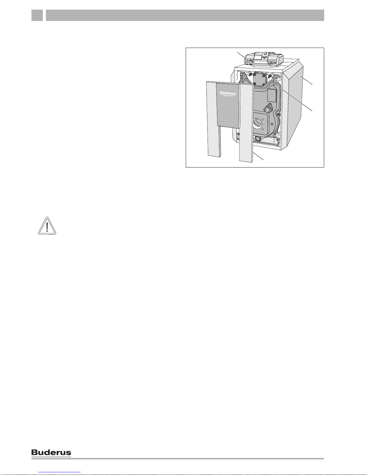
Fig. 1 Boiler without burner
1 Logamatic control panel
2 Boiler jacket
3 Boiler block with insulation
4 Burner door casing
1
2
3
4
CAUTION!
SYSTEM DAMAGE
due to incorrect burner.
z Use only burners that meet the
technical boiler requirements.
Technical information 3
7
We reserve the right to make any changes due to technical modifications.
Installation and maintenance instructions Logano G215 US oil/gas-fired boilers • Issue 11/2004
3 Technical information
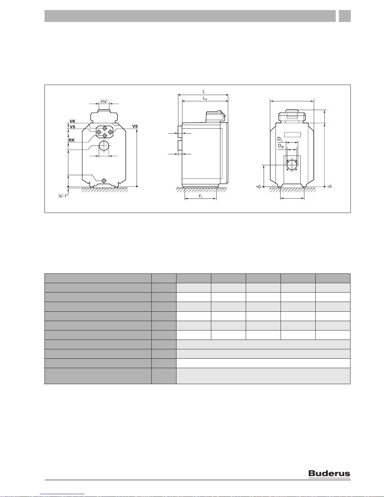
3.1 Technical data for boiler without burner
Select a suitable burner for this boiler using the
information in this chapter.
Fig. 2 Connections and dimensions (measurements in inches)
30¾
29¼
27
21
EL ¾
2¾
6
29¼
4¼
3¼
23½
41
34¾
11¾
1½
1
1½
1
Connections (measurements see following tables):
VK = Boiler supply VS = Hot water tank supply
RK = Boiler return
EL = Boiler drain (connection for drain valve)
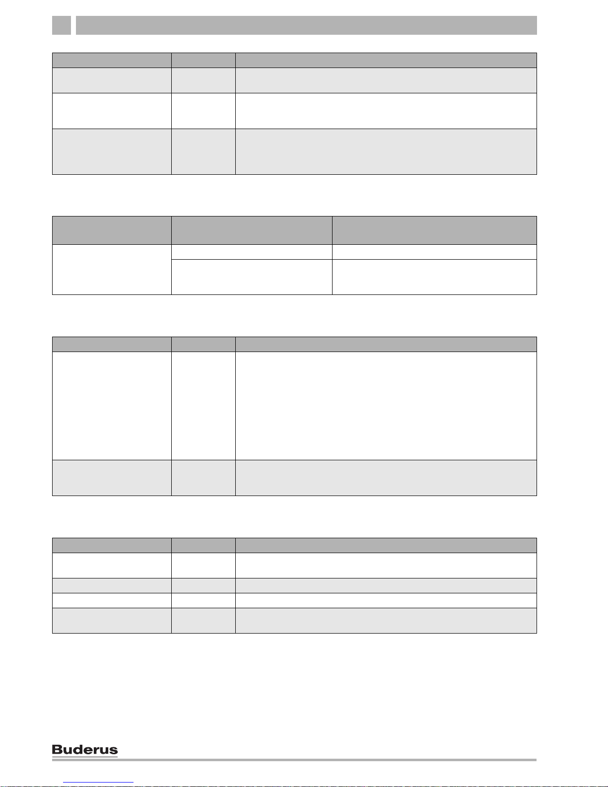
Boiler model 215/3 215/4 215/5 215/6 215/7
Boiler sections Number 3 4 5 6 7
Heating capacity (gross output) Btu/hr 134,000 171,000 207,000 256,000 294,000
Thermal output (net IBR output) Btu/hr 117,000 149,000 180,000 223,000 256,000
Boiler water content Gal approx. 12.9 approx. 16.1 approx. 19.3 approx. 22.5 approx. 25.6
Gas content cu.ft. 1.35 1.73 2.10 2.48 2.86
Oil firing rate GPH 1.1 1.4 1.7 2.1 2.5
Hot gas resistance psi 0.0023 – 0.0078
Permissible max. supply temperature1 °F 248
Allowable operating pressure psi 58
Maximum time constant of thermostat
and high limit safety cut-out (STB)
s 40
Tab. 1 Technical data for boilers without burners
1
Safety limit (high limit safety cut-out STB)
Maximum possible flow temperature = safety limit (STB) – 32 °F
Example: Safety limit (STB) = 212 °F, maximum possible flow temperature = 212 – 32 = 180 °F
The safety limit must comply with the national regulations.
8
Installation and maintenance instructions Logano G215 US oil/gas-fired boilers • Issue 11/2004
We reserve the right to make any changes due to technical modifications.
Technical information3
3.2 Operating conditions
If the operating conditions listed on the following page
are maintained, long and trouble-free operation of the
boiler can be expected. Some details relate only to
operation with Logamatic control panels from Buderus.
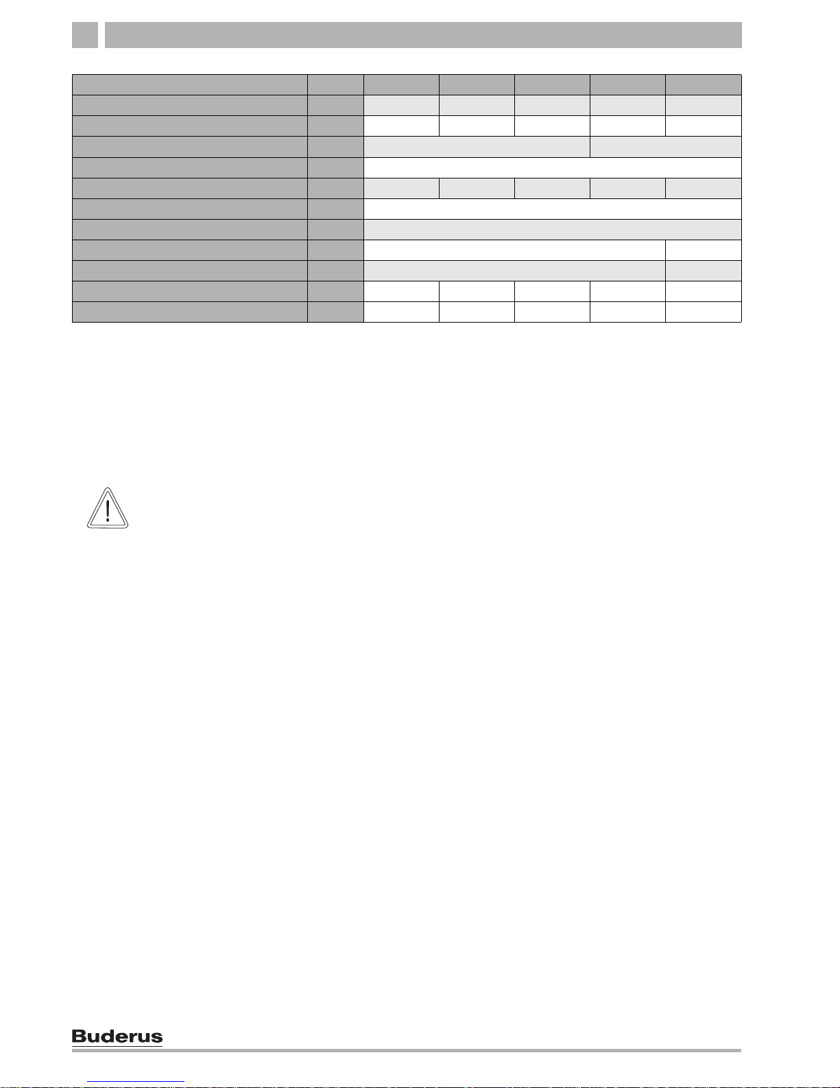
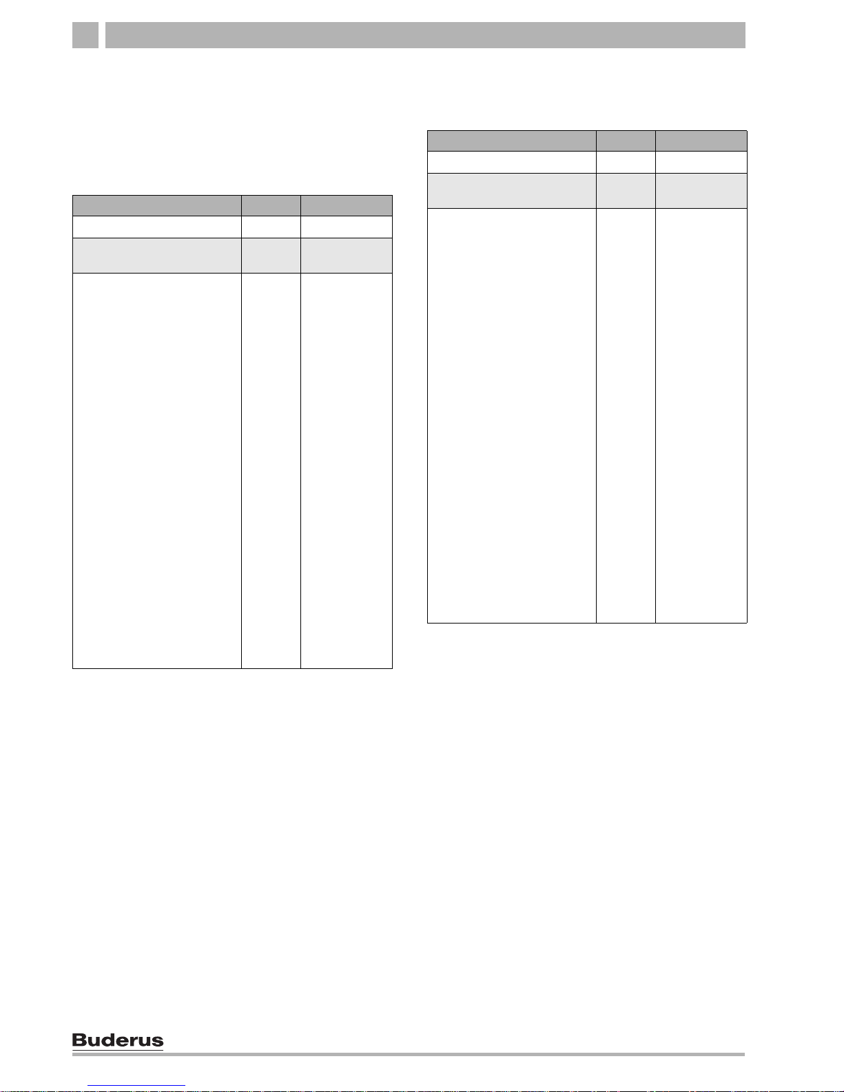
Boiler model 215/3 215/4 215/5 215/6 215/7
Total boiler length (L) Inch 26 ¼ 31 35 ¾ 40 ½ 45 ¼
Boiler block length (LK) Inch 22 26 ¾ 31 ½ 36 ¼ 41
Boiler section insert (width; height; depth) Inch – 18 1/8; 32 ¼; 5 7/
8
Boiler block insert (width; height; depth) Inch 18 1/8; 32 ¼; Length LK
Combustion chamber length Inch 16 ¾ 21 ½ 26 ¼ 31 35 ¾
Combustion chamber diameter Inch 13 ¼
Burner door thickness Inch 3 ¾
Burner pipe diameter (DB) Inch 4 3/
8
5 1/
8
Hole circle diameter (DL) Inch 5 7/
8
6 ¾
Distance between boiler feet (FL) Inch 13 ¼ 18 22 ¾ 27 ¼ 32
Dry weight
1
lbs 400 500 600 700 800
Tab. 2 Dimensions, weight and other data for boilers without burners
1
Weight incl. packaging material approx. 6 – 8 % more.
CAUTION!
SYSTEM DAMAGE
Deviating from the stated operating
conditions may lead to faults. Major
deviations may lead to the destruction of
individual components or of the boiler.
z Observe the details on the boiler rating
label, which are decisive. Please
always observe these.

Technical information 3
9
We reserve the right to make any changes due to technical modifications.
Installation and maintenance instructions Logano G215 US oil/gas-fired boilers • Issue 11/2004
3.2.1 General operating requirements
3.2.2 Boiler room and environmental conditions
Operating conditions
Min. boiler water
temperature
Operating interruption
(complete boiler shutdown)
Heating circuit control with
central heating mixer
1
Min. return temperature
In combination with Logamatic control for variable low-temperature operating modes, such as Logamatic 2107
not obligatory
Operating temperatures are
safeguarded by the
Logamatic control panel
2
automatically by the Logamatic
control panel
not obligatory but advantageous
with low-temperature heating
system design 130/113 °F
Required for:
Underfloor heating systems
Systems with high water content:
>115 gal/MBH
(1 MBH = 100,000 Btu/hr)
Not obligatory, except for
operation with a modulating
burner for:
Oil combustion: 113 °F
Gas combustion: 130 °F
In combination with Logamatic control for constant boiler water temperatures, such as Logamatic 2109
or in combination with remote control and aquastat
150 °F
3
possible if, after interruption of
the operation, there is at least 3
hours heating operation
required required for:
Systems with high water
content >115 gal/MBH: 130 °F
Operation with a modulating
burner: 130 °F
Tab. 3 General operating requirements
1
A heating circuit with a mixer improves controllability and is specifically recommended for systems with several heating circuits.
2
If the control system does not influence the heating circuits or the a heating circuit actuating component (e. g. Pumplogic), the burner ON mode
must reach an operating temperature of 122 °F within 10 min by restricting volume flow.
3
Boiler control thermostat setting: During burner ON mode the minimum boiler water temperature in the boiler must be reached within 10 minutes
by suitable measures, such as flow restriction, and maintained as the minimum temperature.
Operating conditions Notes – Requirement in greater detail
Temperature in the boiler room +40 to +104 °F
relative humidity max. 90 % No condensation or precipitation inside the boiler room
Dust/airborne seeds – Excessive dust inside the boiler room must be avoided when the boiler is
operating, e.g.:
– dust from building work
Combustion air supplied from outside must not be excessively loaded with
dust or airborne seed; if necessary, air filters should be fitted to prevent
this:
– Air supply contaminated with dust from dirt roads and paths.
– Air supply contaminated with dust from production and processing facilities,
e.g. quarries, mines, etc.
– Airborne seed from thistles and similar
Halogen-hydrocarbon
compounds
– The combustion air must be free from halogen-hydrocarbon compounds.
– Identify the source of halogen-hydrocarbon compounds and prevent them
from entering. Where this is impossible, route combustion air from areas that
are not contaminated by halogen-hydrocarbon compounds.
Fans, which extract air from the
boiler room.
– During burner operation, no mechanical air handling equipment may be operated
that could extract combustion air from the boiler room, e.g.:
– Extraction hood
– Clothes dryer
– Ventilation equipment
Tab. 4 Boiler room and ambient conditions
10
Installation and maintenance instructions Logano G215 US oil/gas-fired boilers • Issue 11/2004
We reserve the right to make any changes due to technical modifications.
Technical information3
3.2.3 Combustion air supply conditions
3.2.4 Fuel conditions
3.2.5 Power supply conditions
Small animals – Protect the boiler room and particularly the combustion air inlet against the entry
of small animals, for example by means of a screen.
Fire protection – Maintain clearances between the boiler and flammable materials in accordance
with local regulations. A minimum clearance of 16" is required. Never store
flammable materials or liquids in the vicinity of the boiler.
Flooding – In case of an acute risk of flooding, disconnect the boiler in good time from its fuel
and power supply before water enters the room. Any general and burner
components or control equipment, which come into contact with water, must be
replaced before re-commissioning.
Operating conditions Notes – Requirement in greater detail
Tab. 4 Boiler room and ambient conditions
Operating conditions
Boiler output (in case of several
boilers = total output)
Ventilation air cross-section in square inches
(unrestricted aperture)
Ventilation cross-section for
combustion air from outside
(split over a maximum of
2 apertures)
< 170,000 Btu/hr min. 23,25 square inches
> 170,000 Btu/hr min. 23,25 square inches and also 0.91 square inches
per 10,000 Btu/hr,
that is above 170,000 Btu/hr
Tab. 5 Combustion air supply – observe local requirement for operation with room air.
Operating conditions Notes – Requirement in greater detail
Permissible fuels for boilers
without integral burners
– This boiler can be operated with the following fuels. Select a burner that is suitable
for one of these fuel types:
– Fuel oil in accordance with the burner specification
If a poorer quality oil (kinematic viscosity > 0.0093 sq in/sec (> 45.5 s
Sayboldt) at 68 °F) is used, the maintenance and cleaning periods must be
reduced. In that case, carry out maintenance and cleaning procedures at least
twice a year.
– Natural gas in accordance with the burner specification
– LPG in accordance with the burner specification
Contamination – Technically free of contaminants (for example dust, mist, humidity), i.e. a
constant operation will not lead to accumulation, which causes reductions in the
cross-section of valves, strainers and filters.
Tab. 6 Fuels
Operating conditions Notes – Requirement in greater detail
Power supply voltage 110 – 120 V Note the voltage range of the burner and control devices used. The housing/boiler
must be grounded for reasons of function and personnel protection.
Fuse (Logamatic) 10 A
Frequency 60 Hz Sinusoidal voltage curve
Protection – IP40 (protected against contact by entry of foreign bodies > 0.04 inches Ø
(> 1 mm Ø), no water proofing)
Tab. 7 Power supply

Technical information 3
11
We reserve the right to make any changes due to technical modifications.
Installation and maintenance instructions Logano G215 US oil/gas-fired boilers • Issue 11/2004
3.2.6 Hydraulic conditions and water quality
Operating conditions Notes – Requirement in greater detail
Operating pressure
(overpressure)
15 – 58 psi Maximum 30 psi with the supplied safety valve.
Permissible site test pressure 45 – 75 psi
Protection against overtemperatures with TR
thermostat
122 – 194 °F
Temperature safety limit by
STB safety temperature cut-out
212 – 248 °F On some controls adjustable on site from 212 to 248 °F.
Water quality – Use only drinking water to fill and top-up the boiler. We recommend a pH value
of 8.2 – 9.5.
Tab. 8 Hydraulic system and water quality
Packaging and Components4
12
Installation and maintenance instructions Logano G215 US oil/gas-fired boilers • Issue 11/2004
We reserve the right to make any changes due to technical modifications.
4 Packaging and Components
z After delivery, check all packaging for concealed
damage.
z Check the delivery for completeness.
Boiler as assembled block
Boiler in parts
Component Qty Packaging
Boiler block 1 1 pallet
1
Control panel,
or aquastat
1 1 box
Jacket Package:
– Boiler jacket
– Insulation
– Burner door, burner door
cover and assembly
equipment
2
– Technical documents
B-Kit components:
– Supply manifold (11/4")
– 30 psi relief valve
– Boiler drain (¾")
– Pressure/temperature
gauge
– 90°-elbow (¾")
– Burner mounting studs and
washers
– Aquastat well (¾")
– Bushing 1" x ¾"
– Plug 1"
1
1
1
1
1
1 box on a
pallet
1 box
1
1 box
1
1 box
1
1 plastic
package
1 package
Tab. 9 Packaging
1
1 pallet
2
The screw-in feet are in the burner door and burner door cover
package.
Component Qty Packaging
Front, center and back sections 1 1 pallet
Control panel,
or aquastat
1 1 box
Jacket Package:
– Fittings
– Boiler jacket
– Insulation
– Burner door, burner door
cover and assembly
equipment
2
– Technical documents
B-Kit components:
– Supply manifold (11/4")
– 30 psi relief valve
– Boiler drain (¾")
– Pressure/temperature
gauge
– 90°-elbow (¾")
– Burner mounting studs and
washers
– Aquastat well (¾")
– Bushing 1" x ¾"
– Plug 1"
1
1
1
1
1
1
1 box on a
pallet
1 box
1
1 box
1
1 plastic
package
1
1 box
1
1 plastic
package
1 package
Tab. 10 Packaging
1
1 pallet
2
The screw-in feet are in the burner door and burner door cover
package.

Moving the boiler 5
13
We reserve the right to make any changes due to technical modifications.
Installation and maintenance instructions Logano G215 US oil/gas-fired boilers • Issue 11/2004
5 Moving the boiler
This chapter details how to move the boiler safely.
CAUTION!
SYSTEM DAMAGE
due to bumps.
z Please observe the handling directions
on the packaging to protect
components from bumps and rough
treatment.
NOTICE
Protect boiler connections from damage
and dirt if the boiler is not installed
immediately.
NOTICE
Dispose of packaging in an
environmentally responsible manner.
CAUTION!
RISK OF INJURY
by not securing the boiler adequately
during transport.
z Use only suitable means for
transportation, e.g. a trolley with strap,
a stair or step trolley.
z Secure the load against falling.
14
Installation and maintenance instructions Logano G215 US oil/gas-fired boilers • Issue 11/2004
We reserve the right to make any changes due to technical modifications.
Placing the Boiler6
6 Placing the Boiler
This chapter details how to install and place the boiler in
the boiler room.
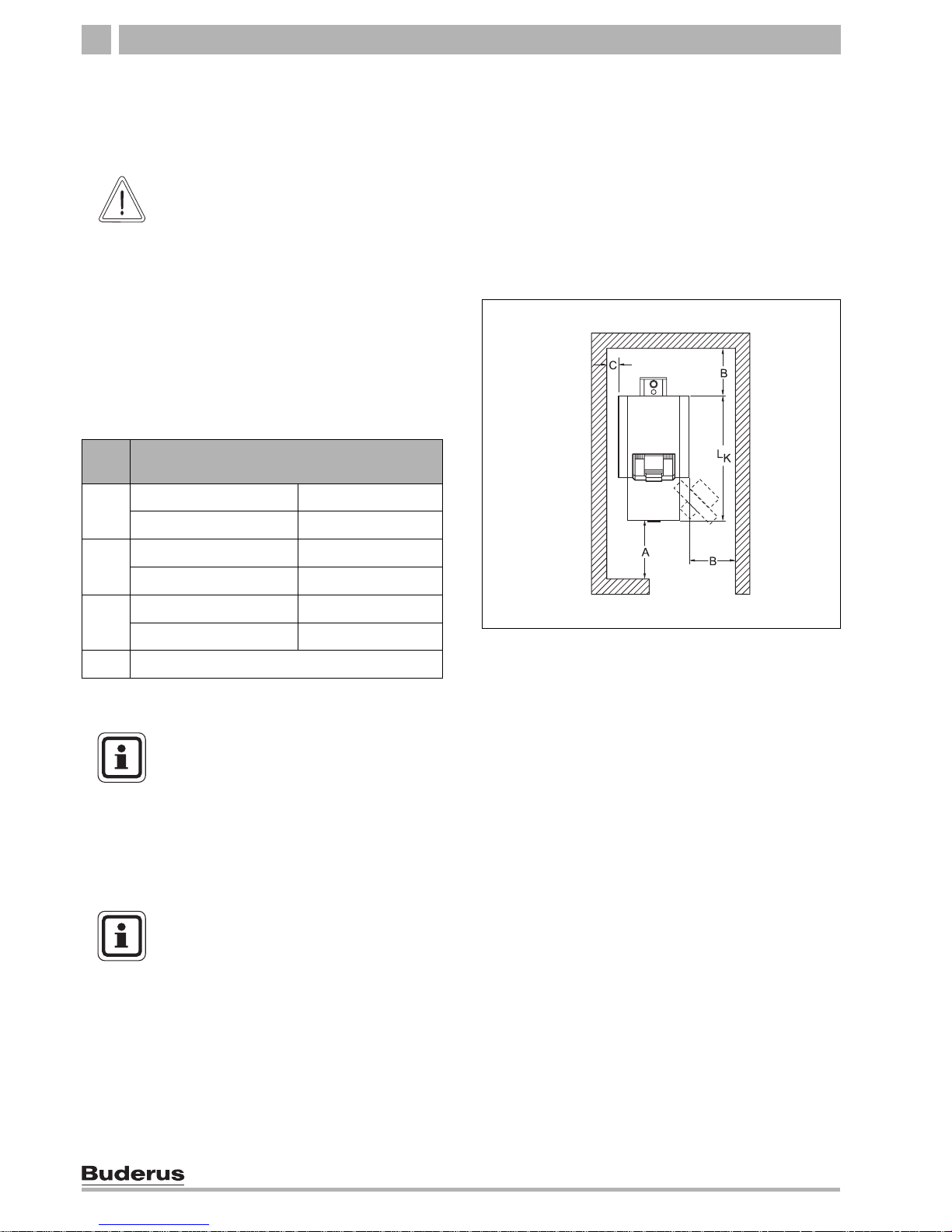
6.1 Clearances
Position the boiler at the recommended clearances
(Î Fig. 3). Reducing the minimum clearances makes
the boiler more difficult to access.
The boiler base or foundation must be perfectly flat and
level.
The burner door can be fitted with the hinge on the l.h.
or the r.h. side.
CAUTION!
SYSTEM DAMAGE
due to freezing temperatures.
z Install the boiler in a frost-free room.
Fig. 3 Boiler room clearances (see Tab. 11)
Mea-
sure
Distance
A Recommended 51 1/8"
minimum 39 3/8"
B Recommended 27 1/2"
minimum 15 3/4"
C Recommended 15 3/4"
minimum 3 7/8"
L
K
see "Technical Data" chapter
Tab. 11 Recommended and minimum clearances
(in inches)
NOTICE
Reduced clearances must comply with
local and state codes. The boilers are
designed for a side clearance of 6". Make
sure that there is a sufficient clearance
between combustible materials and the
chimney connection as specified by
NFPA 31 (distance of 18").
NOTICE
Where applicable, allow extra wall
clearances for additional components,
for example hot water tank, pipe
connections, flue gas muffler or other
components on the flue gas side.
Boiler block assembly 7
15
We reserve the right to make any changes due to technical modifications.
Installation and maintenance instructions Logano G215 US oil/gas-fired boilers • Issue 11/2004
7 Boiler block assembly
The on-site installation is carried out using individual
sections if, because of physical limitations, a boiler block
cannot be assembled as a complete unit.
For installation of boiler supplied fully assembled
(Î Chapter 7.3, page 26).
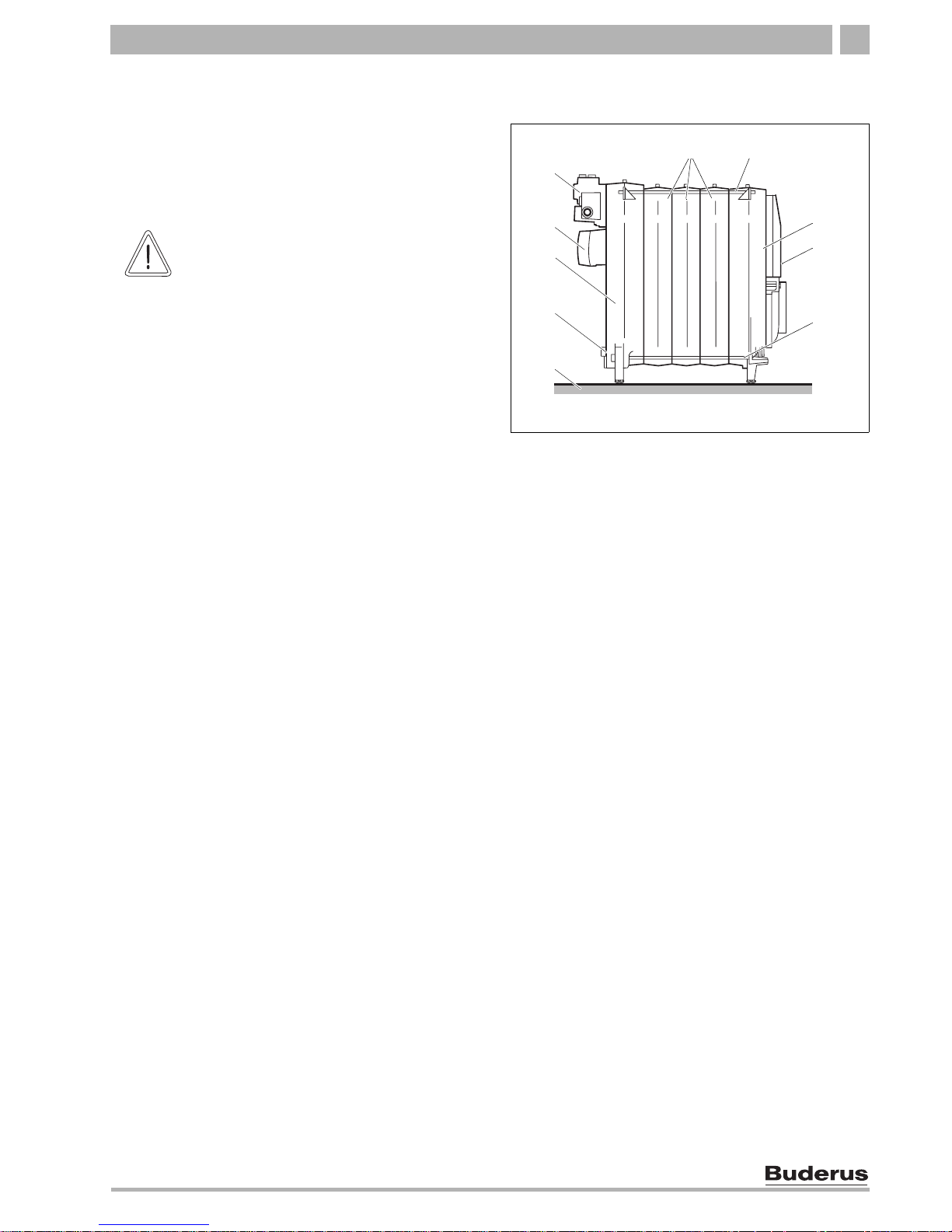
Fig. 4 Boiler block in the assembled state
1 Foundation/installation location
2 Drain
3 Back section
4 Flue outlet
5 Connecting block
6 Central sections
7 Anchor rods
8 Front section
9 Burner door
1
3
4
6
7
8
5
9
2
7
CAUTION!
RISK OF INJURY
by not securing the boiler adequately
during transport.
z Use only suitable means for
transportation, e.g. a trolley with strap, a
stair or step trolley.
z Secure the load against falling.
16
Installation and maintenance instructions Logano G215 US oil/gas-fired boilers • Issue 11/2004
We reserve the right to make any changes due to technical modifications.
Boiler block assembly7
7.1 Assembly when delivered in sections
z Assemble all boiler sections in accordance with the
following instructions and diagrams.
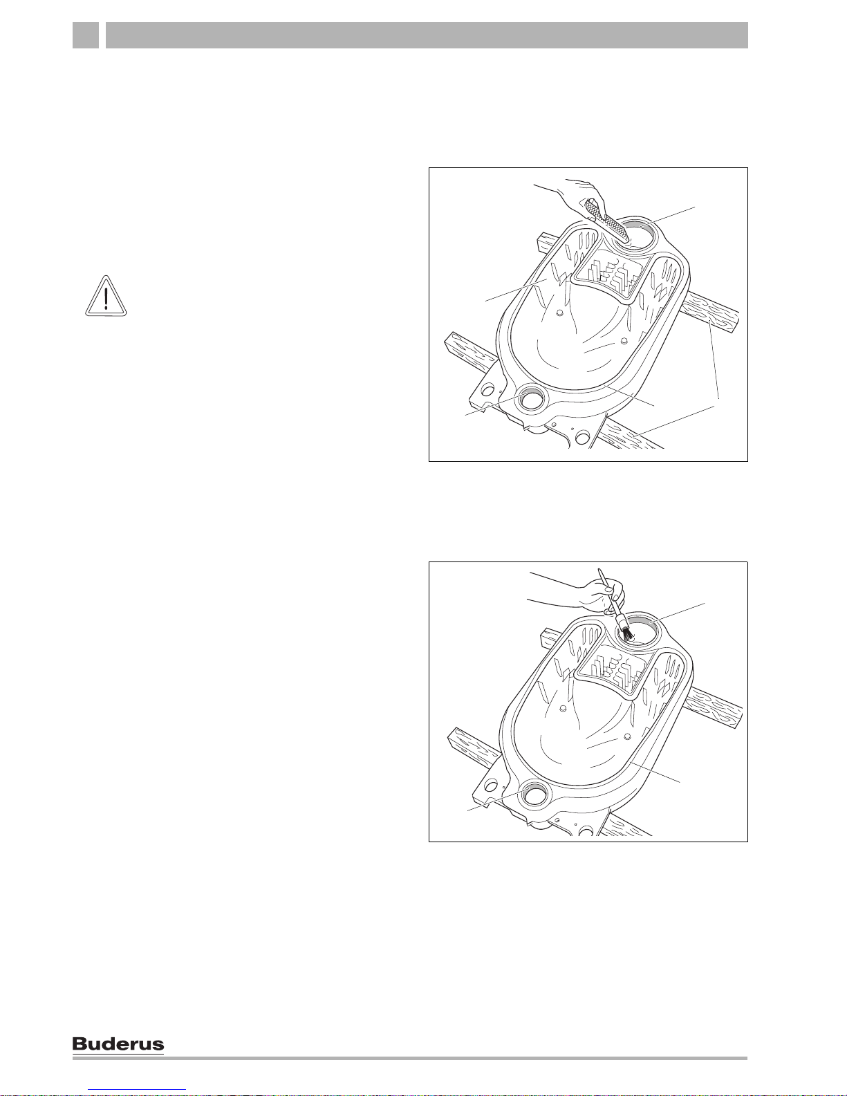
7.1.1 Preparing boiler sections
z Position the rear section onto two wood blocks.
z Clean the boiler hubs with sandpaper and a rag.
z Remove any burrs with a file.
z Clean the packing spring or packing groove with a
wire brush and rag.
z Clean the hub sealing faces with a rag soaked in
cleaning agent.
z Evenly coat the boiler hub sealing faces with red lead
putty.
z Coat the packing spring or packing groove with
adhesive (adhesive base).
Fig. 5 Remove burrs
1 Boiler hubs
2 Back section
3 Wood blocks
4 Sealing spring
3
1
2
1
4
CAUTION!
RISK TO HEALTH and
DANGER OF BURNS
due to released vapors and easily
flammable cleaning agents.
z When using red lead putty, adhesives
and solvents ensure adequate
ventilation inside the installation room.
z When using solvents, avoid open
flames, incandescence and sparks.
z Please observe the manufacturer's
handling and safety instructions.
Fig. 6 Coat boiler hubs with red lead putty
1 Boiler hub sealing face
2 Sealing spring
1
1
2
Boiler block assembly 7
17
We reserve the right to make any changes due to technical modifications.
Installation and maintenance instructions Logano G215 US oil/gas-fired boilers • Issue 11/2004
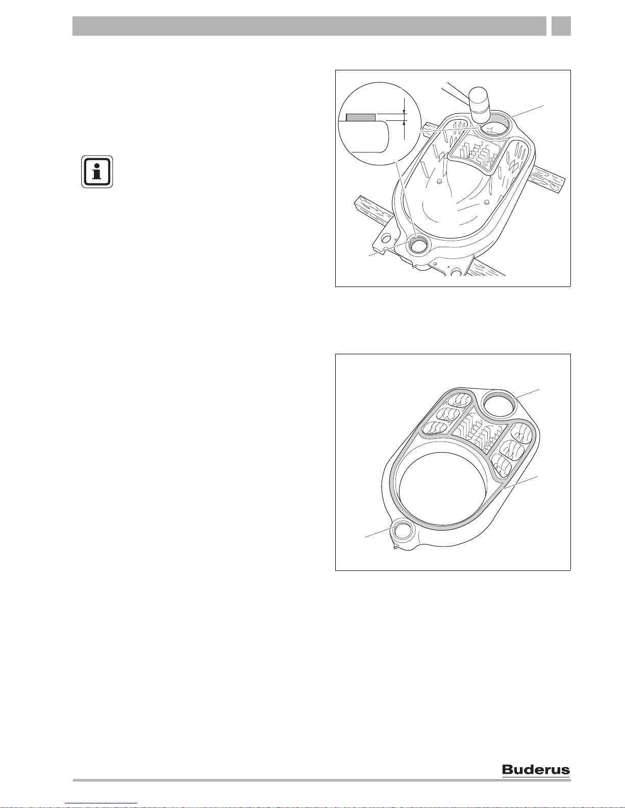
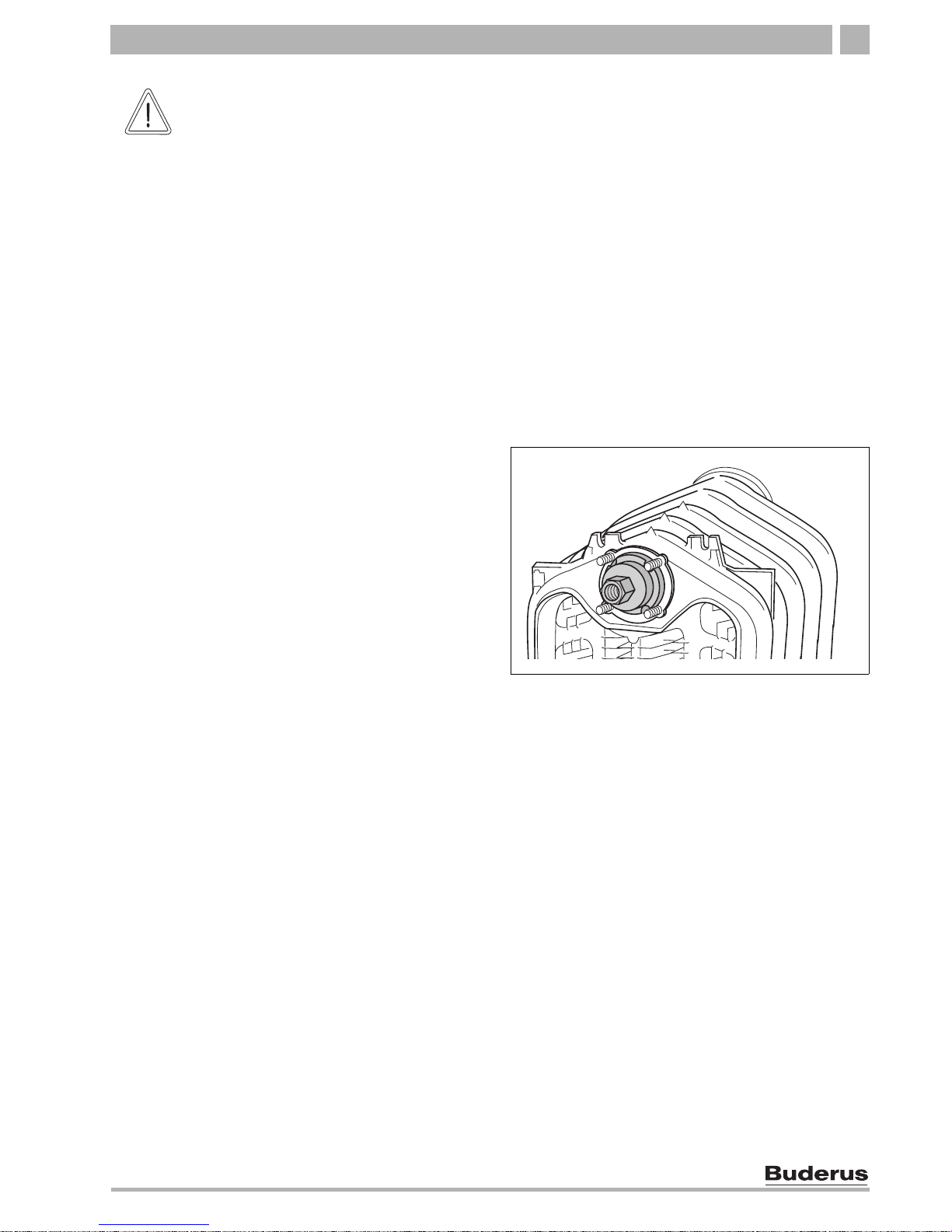
7.1.2 Preparing push nipples and nipple ports
z Clean the nipples with a cloth soaked in cleaning
agent.
z Evenly coat the nipples with red lead putty.
z Place nipple straight in the top and bottom boiler hub
of the back section and hammer in a crosswise
pattern.
z Remove any burrs with a file.
7.1.3 Preparing the intermediate section
Prepare the central section in the same way as the back
section (Î Chapter 7.1.1, page 16).
Fig. 7 Driving nipples home
1 Nipple in the upper boiler hub
2 Nipple in bottom boiler hub
30
2
1
1 1/8
NOTICE
After driving in the nipple leave it projecting
approx. 1 1/8" from the boiler hub.
Fig. 8 Preparing the central section
1 Boiler hub sealing face
2 Packing grooves
1
1
2
18
Installation and maintenance instructions Logano G215 US oil/gas-fired boilers • Issue 11/2004
We reserve the right to make any changes due to technical modifications.
Boiler block assembly7
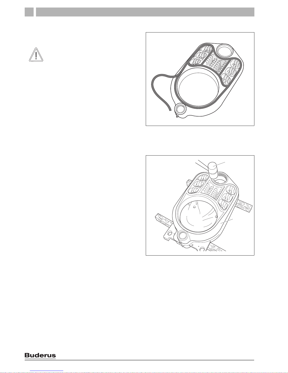
7.1.4 Inserting the section sealing
z Unroll the required length of section sealing from the
roll supplied.
z Peel the backing paper from the sealing rope as you
insert the cord into the packing groove.
z Insert the flexible sealing rope into the packing
groove starting in the upper boiler hub area, and
lightly press in.
z Overlap sealing rope 3/4" at the joins and press in
well.
7.1.5 Knock intermediate section into place
z Turn the intermediate section around and locate with
the upper and lower boiler hubs on the nipples of the
rear section.
z Drive the intermediate section onto the rear section
using a wood or a rubber mallet.
Fig. 9 Inserting the section sealing rope
CAUTION!
SYSTEM DAMAGE
due to leaking boiler sections.
z To ensure that the faces between the
boiler sections are sealed correctly
never stretch the sealing rope during
application.
z Carefully insert the sealing rope into the
boiler section packing grooves.
Fig. 10 Knock intermediate section into place
1 Wood or rubber mallet
2 Rear section
1
2
Boiler block assembly 7
19
We reserve the right to make any changes due to technical modifications.
Installation and maintenance instructions Logano G215 US oil/gas-fired boilers • Issue 11/2004
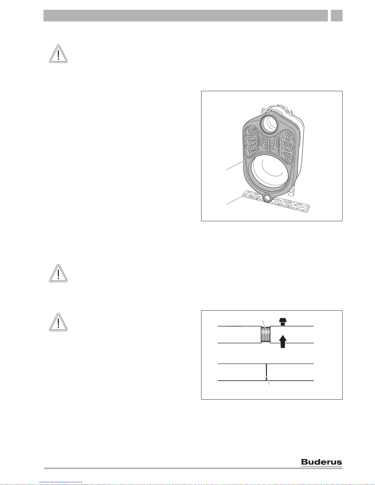
7.1.6 Boiler section alignment
z Position the partly assembled block of two boiler
sections.
z Position a flat board underneath the center section
so that the boiler block is slightly tilted for the
continuing assembly.
7.1.7 Join boiler sections by the nipples at the top and bottom boiler hub
CAUTION!
RISK OF INJURY
due to inadequately secured boiler
sections.
z Secure the boiler block section against
tipping.
Fig. 11 Installing boiler block section
1 Flat board
2 Center section
1
2
CAUTION!
BOILER DAMAGE
due to unsuitable compression tool.
z Use only the compression tool size 1.2
(Î documents for compression tool)
suitable for the boiler.
Fig. 12 Making the pull rod threaded connection
1 Pull rod threaded connection (incorrectly joined)
2 Pull rod threaded connection (correctly joined)
1
2
CAUTION!
COMPRESSION TOOL DAMAGE
The compression tool may be damaged or
destroyed, if you compress pull rods with
loose threaded connections.
z Check the threaded connection of the
pull rods after every compression, and
tighten, if required.
The pull rod is correctly positioned if it is
fully inserted and no thread is showing.
z Keep the thread of the compression tool
clean. Dirty threads can damage the
compression tool during compression.

20
Installation and maintenance instructions Logano G215 US oil/gas-fired boilers • Issue 11/2004
We reserve the right to make any changes due to technical modifications.
Boiler block assembly7
z Push one pull rod each through the lower and the
upper boiler hub of the partly assembled block.
z Push the auxiliary flange onto the pull rods of the
lower and upper boiler hubs.
z Push the mating flange onto the pull rod of the lower
and upper boiler hubs, and secure with the
respective wedges.
z Thread the compression units onto the pull rod
threads.
z Hold the pull rods at the center of the boiler hubs and
slightly draw together the compression tools using
the compression unit.
z Set both ratchet wrenches on the clamping nuts of
the compression units and press the boiler sections
together by evenly tightening the nuts.
Fig. 13 Compression tool assembled at the upper boiler hub
1 Compression unit
2 Auxiliary flange (Ø 5 3/8" × 1" top boiler hub)
3 Mating flange (Ø 5 3/8" × 1" top boiler hub)
4 Wedge
5 Pull rod in the upper boiler hub
1
2
435
CAUTION!
BOILER DAMAGE
due to incorrectly positioned auxiliary
flange.
Leaks may occur if the auxiliary flange sits
on the packing spring/groove of the boiler
section during the compression process.
z Ensure that the auxiliary flange lies
level on the boiler hubs.
Fig. 14 Compression tool assembled at the lower boiler hub
1 Compression unit
2 Auxiliary flange (Ø 3 1/8" × 1")
3 Mating flange (Ø 3 1/8" × 1" bottom boiler hub)
4 Wedge
5 Pull rod in the bottom boiler hub
1
2
3
4
5
NOTICE
Push the compression units far enough
onto the pull rod threads that two thread
windings protrude from the compression
units.
Fig. 15 Positioning ratchet
1 Ratchet
2 Clamping nut
1
2
Boiler block assembly 7
21
We reserve the right to make any changes due to technical modifications.
Installation and maintenance instructions Logano G215 US oil/gas-fired boilers • Issue 11/2004
z Release and remove the compression tool.
z Hammer the nipples into the partly assembled boiler
block (Î Chapter 7.1.2, page 17).
z Prepare all other intermediate sections as described
above and join them at the nipples.
Fitting the front section
Due to the threaded studs, do not use the auxiliary
flange at the front of the upper boiler hub when
assembling the front section.
z Push the pull rod together with the compression unit
through the upper boiler hub.
z Carry out all other steps as described
(Î Chapter 7.1.7, page 19)
CAUTION!
BOILER DAMAGE
due to leaking boiler sections.
z For each compression procedure
ensure that no more than one nipple
joint (one nipple joint comprises two
sections) is compressed.
z Never jam nipples into the boiler hubs of
the boiler section.
z Stop pressing the sections together
when the boiler hubs meet.
Fig. 16 Fit the compression tool to the front section
22
Installation and maintenance instructions Logano G215 US oil/gas-fired boilers • Issue 11/2004
We reserve the right to make any changes due to technical modifications.
Boiler block assembly7
7.1.8 Fitting the anchor rods
z Insert the anchor rods with spring washers into the
case cams on the l.h. and r.h. side as well as
adjacent to the lower boiler hubs.
z Tighten the nuts on the anchor rod threads by hand.
z Tighten the nuts 1 to 1½ turns on the anchor rods.
z Release and remove the compression tool.
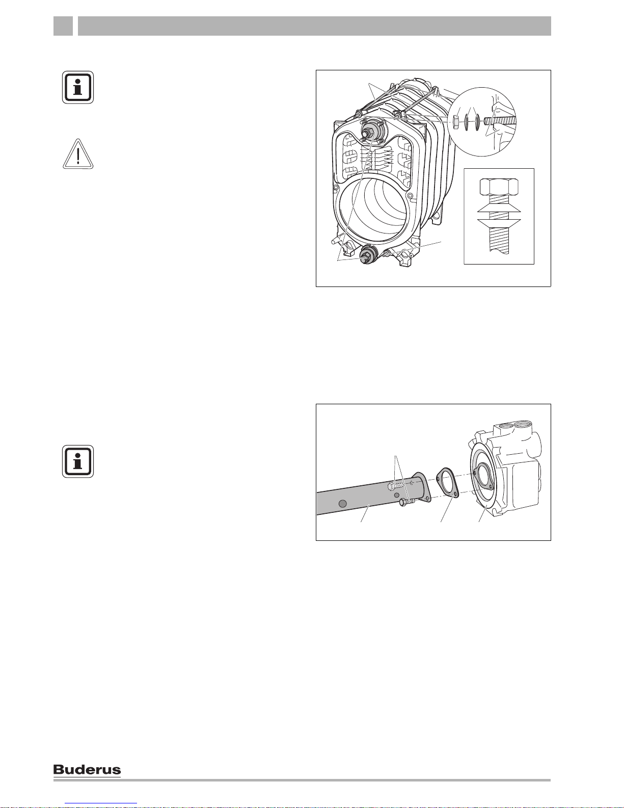
7.1.9 Fitting distribution tube and supply/return header
The distribution tube, the supply/return header and the
sensor well are already assembled if the boiler block is
supplied as a ready assembled unit.
z Secure the distribution tube to the supply/return
header with M 8 × 16 screws and flat gasket.
Fig. 17 Fitting the anchor rods – layout of spring washers
1 Anchor rods
2 Nut
3 Spring washers
4 Cast lugs
5 Compression tool
6 Spring washer arrangement
1
1
2
3
5
4
A
NOTICE
Insert the anchor rods before removing the
compression tool.
Never remove the compression tool first.
CAUTION!
SYSTEM DAMAGE
due to incorrect spring washer assembly.
z Ensure that the spring
washers are arranged opposite each
other on the anchor rods.
Fig. 18 Fitting feed pipe on supply/return header
1 supply/return header
2 Flat gasket
3 Distribution tube
4 M 8 × 16 bolts (brass)
123
4
NOTICE
Before installation of the supply/return
header, first push the distribution tube from
the boiler front into the boiler (don't forget
the boiler hub flat gasket) if insufficient
space is available behind the boiler.
 Loading...