

Buderus Logano G125 BE US/CA, Logano G125/21-BE, Logano G125/28-BE, Logano G125/34-BE Installation And Service Instructions Manual
Page 1
Installation and Service
Instructions
Low Emissions and
High Efficiency Oil
Boiler
C
Logano G125 BE US/CA
For trained and certified
installers
Read carefully prior to
installation, maintenance
and service.
6 720 804 880 (2012/10) EN-US
Page 2

Table of Contents
1 Safety Considerations and Symbol Descriptions . . . . . . . . . . . . . . . . . . . 4
1.1 Regarding this Manual . . . . . . . . . . . . . . . . . . . . . . . . . . . . . . . . . . . . . . . . 4
1.2 Guideline of Notices . . . . . . . . . . . . . . . . . . . . . . . . . . . . . . . . . . . . . . . . . 4
1.3 Observe the following Symbols . . . . . . . . . . . . . . . . . . . . . . . . . . . . . . . . . . 4
1.3.1 Installation Guidelines . . . . . . . . . . . . . . . . . . . . . . . . . . . . . . . . . . . . . . . 5
1.3.2 Boiler Room Guidelines . . . . . . . . . . . . . . . . . . . . . . . . . . . . . . . . . . . . . . 5
1.4 Tools, Materials and Accessories . . . . . . . . . . . . . . . . . . . . . . . . . . . . . . . . . 5
1.5 Disposal . . . . . . . . . . . . . . . . . . . . . . . . . . . . . . . . . . . . . . . . . . . . . . . . . 5
2 Product Description. . . . . . . . . . . . . . . . . . . . . . . . . . . . . . . . . . . . . . . . . . 6
2.1 Product Applications . . . . . . . . . . . . . . . . . . . . . . . . . . . . . . . . . . . . . . . . . 6
2.2 Product Description . . . . . . . . . . . . . . . . . . . . . . . . . . . . . . . . . . . . . . . . . . 6
3 Technical Information . . . . . . . . . . . . . . . . . . . . . . . . . . . . . . . . . . . . . . . . 7
3.1 Technical Data less Burner . . . . . . . . . . . . . . . . . . . . . . . . . . . . . . . . . . . . . 7
3.2 Operating Conditions . . . . . . . . . . . . . . . . . . . . . . . . . . . . . . . . . . . . . . . . . 8
3.2.1 General Operating Requirements . . . . . . . . . . . . . . . . . . . . . . . . . . . . . . . . . 9
4 Packaging and Components . . . . . . . . . . . . . . . . . . . . . . . . . . . . . . . . . . 12
5 Moving the Boiler. . . . . . . . . . . . . . . . . . . . . . . . . . . . . . . . . . . . . . . . . . . 13
5.1 Reducing Boiler Weight for Transportation. . . . . . . . . . . . . . . . . . . . . . . . . . . 13
5.2 Lifting and Carrying the Boiler . . . . . . . . . . . . . . . . . . . . . . . . . . . . . . . . . . 14
5.3 Moving the Boiler with the Boiler Cart. . . . . . . . . . . . . . . . . . . . . . . . . . . . . . 14
6 Placing the Boiler. . . . . . . . . . . . . . . . . . . . . . . . . . . . . . . . . . . . . . . . . . . 15
6.1 Clearances . . . . . . . . . . . . . . . . . . . . . . . . . . . . . . . . . . . . . . . . . . . . . . 15
6.2 Reversing the Burner Door Swing . . . . . . . . . . . . . . . . . . . . . . . . . . . . . . . . 16
6.3 Installation of boiler Feet (Components of B-Kit) . . . . . . . . . . . . . . . . . . . . . . . 17
6.4 Placement of the Boiler . . . . . . . . . . . . . . . . . . . . . . . . . . . . . . . . . . . . . . 17
7 Boiler Installation. . . . . . . . . . . . . . . . . . . . . . . . . . . . . . . . . . . . . . . . . . . 18
7.1 Installation of Venting Systems. . . . . . . . . . . . . . . . . . . . . . . . . . . . . . . . . . 18
7.1.1 Vertical Venting Systems. . . . . . . . . . . . . . . . . . . . . . . . . . . . . . . . . . . . . 19
7.1.2 Horizontal Venting . . . . . . . . . . . . . . . . . . . . . . . . . . . . . . . . . . . . . . . . 19
7.2 Installation of Combustion Air Supply System. . . . . . . . . . . . . . . . . . . . . . . . . 28
7.3 Installation of Water Connections . . . . . . . . . . . . . . . . . . . . . . . . . . . . . . . . 31
7.3.1 B-Kit Installation . . . . . . . . . . . . . . . . . . . . . . . . . . . . . . . . . . . . . . . . . 31
7.3.2 Installation of Boiler Drain (B-Kit Component) . . . . . . . . . . . . . . . . . . . . . . . . . . 32
7.3.3 Installation of System Components . . . . . . . . . . . . . . . . . . . . . . . . . . . . . . . 32
7.4 Filling and Checking for Water Leaks . . . . . . . . . . . . . . . . . . . . . . . . . . . . . . 33
7.5 Installation of Oil Line. . . . . . . . . . . . . . . . . . . . . . . . . . . . . . . . . . . . . . . . 34
7.6 Electrical Connections . . . . . . . . . . . . . . . . . . . . . . . . . . . . . . . . . . . . . . . 35
7.6.1 Installation of Aquasmart . . . . . . . . . . . . . . . . . . . . . . . . . . . . . . . . . . . . . 35
7.6.2 Control System Installation. . . . . . . . . . . . . . . . . . . . . . . . . . . . . . . . . . . . 36
7.6.5 Strain Relief Installation . . . . . . . . . . . . . . . . . . . . . . . . . . . . . . . . . . . . . 38
7.6.6 Top Rear Panel Installation . . . . . . . . . . . . . . . . . . . . . . . . . . . . . . . . . . . 38
2
Logano G125 BE - Specifications subject to change without notice.
Page 3

Table of Contents
8 Placing the Boiler in Operation . . . . . . . . . . . . . . . . . . . . . . . . . . . . . . . . . 39
8.1 Setting the Initial System Pressure . . . . . . . . . . . . . . . . . . . . . . . . . . . . . . . . 39
8.2 Checking the Relief Valve . . . . . . . . . . . . . . . . . . . . . . . . . . . . . . . . . . . . . 40
8.3 Check Position of Flue Baffles (Room Air Operation). . . . . . . . . . . . . . . . . . . . . 40
8.4 Check Position of Flue baffle Plates (Outside Air Operation) . . . . . . . . . . . . . . . . 41
8.5 Prepare System for Operation . . . . . . . . . . . . . . . . . . . . . . . . . . . . . . . . . . . 41
8.6 Start-up of Control and Burner. . . . . . . . . . . . . . . . . . . . . . . . . . . . . . . . . . . 41
8.7 Guidelines for Burner Start-up . . . . . . . . . . . . . . . . . . . . . . . . . . . . . . . . . . . 41
8.8 Adjusting Stack Temperatures. . . . . . . . . . . . . . . . . . . . . . . . . . . . . . . . . . . 42
8.8.1 Adjusting/Removing Flue Baffles . . . . . . . . . . . . . . . . . . . . . . . . . . . . . . . . . 43
8.8.2 Removing Flue Blocking Plate. . . . . . . . . . . . . . . . . . . . . . . . . . . . . . . . . . . 44
8.9 Testing of the Manual Reset High Limit (STB) of Logamatic controls . . . . . . . . . . . 44
8.10 Installation of Front Burner Cover . . . . . . . . . . . . . . . . . . . . . . . . . . . . . . . . . 45
8.11 Detailed Start-up Procedure . . . . . . . . . . . . . . . . . . . . . . . . . . . . . . . . . . . . 46
9 Taking the Boiler Out of Operation . . . . . . . . . . . . . . . . . . . . . . . . . . . . . . 47
9.1 Normal Boiler Shut-down . . . . . . . . . . . . . . . . . . . . . . . . . . . . . . . . . . . . . . 47
9.2 Emergency Shut-down . . . . . . . . . . . . . . . . . . . . . . . . . . . . . . . . . . . . . . . 47
10 Boiler Maintenance . . . . . . . . . . . . . . . . . . . . . . . . . . . . . . . . . . . . . . . . . . 48
10.1 Why do maintenance?. . . . . . . . . . . . . . . . . . . . . . . . . . . . . . . . . . . . . . . . 48
10.2 Prepare Boiler for Cleaning. . . . . . . . . . . . . . . . . . . . . . . . . . . . . . . . . . . . . 48
10.3 Boiler Cleaning . . . . . . . . . . . . . . . . . . . . . . . . . . . . . . . . . . . . . . . . . . . . 49
10.3.1Cleaning the Boiler with Brushes . . . . . . . . . . . . . . . . . . . . . . . . . . . . . . . . . 49
10.3.2Wet Cleaning . . . . . . . . . . . . . . . . . . . . . . . . . . . . . . . . . . . . . . . . . . . 50
10.3.3Inspecting the combustion air hose (sealed combustion only) . . . . . . . . . . . . . . . . . . 50
10.4 Testing System Pressure . . . . . . . . . . . . . . . . . . . . . . . . . . . . . . . . . . . . . . 51
10.5 Testing Relief Valve . . . . . . . . . . . . . . . . . . . . . . . . . . . . . . . . . . . . . . . . . 51
10.6 Inspection and Maintenance Procedure . . . . . . . . . . . . . . . . . . . . . . . . . . . . . 52
11 Restoring System Lock-outs. . . . . . . . . . . . . . . . . . . . . . . . . . . . . . . . . . . 56
12 Piping Diagrams . . . . . . . . . . . . . . . . . . . . . . . . . . . . . . . . . . . . . . . . . . . . 57
13 Spare Parts . . . . . . . . . . . . . . . . . . . . . . . . . . . . . . . . . . . . . . . . . . . . . . . . 60
14 Burner Wiring Examples . . . . . . . . . . . . . . . . . . . . . . . . . . . . . . . . . . . . . . 67
15 Glossary . . . . . . . . . . . . . . . . . . . . . . . . . . . . . . . . . . . . . . . . . . . . . . . . . . 69
Logano G125 BE - Specifications subject to change without notice.
3
Page 4
1
Î
Safety Considerations and Symbol Descriptions
1 Safety Considerations and Symbol Descriptions
1.1 Regarding this Manual
This document contains important information regarding
safe and proper installation, operation and maintenance
of the boiler.
The high tech G125 BE boiler is designated as a hot water heating boiler.
The Installation and Maintenance Instructions are directed to the installing contractor who has professional
knowledge regarding boiler installation and maintenance.
1.2 Guideline of Notices
Two levels of danger are identified by the following
warning labels:
DANGER
Denotes a possible severely dangerous
WARNING!
CAUTION!
situation where, without proper caution,
bodily injury or loss of life may result.
DANGER OF INJURY/SYSTEM
DAMAGE
Denotes a possible dangerous situation
that can lead to mild to moderate bodily injury or physical damage.
1.3 Observe the following Symbols
The local and state codes and regulations must be observed during the installation of the boiler:
– The local building code requirements regarding
placement, combustion air and venting and chimney
system must be followed.
– Follow applicable electrical code requirements.
– Follow the local code and standards regarding safe
boiler operation.
NOTICE
Use only original Buderus spare parts.
Buderus can not be held liable for damage caused by non-Buderus parts.
NOTICE
The boiler installation must be performed
by a qualified installer in accordance with
regulations put forth in NFPA-31 Installation of Oil-Burning Equipment. The installation must comply with all local and
national codes, regulations and authorities having jurisdiction regarding the installation of oil fired boilers.
For Canada refer to the guidelines of
CSA/CGA-B149.1 and 2 Installation
Codes.
NOTICE
Application comment for optimum use of
equipment and adjustment as well as
useful information.
Cross reference
Designated by means of an arrow Î , refers to a notice
in another document.
4
Logano G125 BE - Specification s subject to change without notice.
Page 5
Safety Considerations and Symbol Descriptions
1
1.3.1 Installation Guidelines
DANGER TO LIFE
from electric shock
CAUTION!
z Do not work on electrical components
unless you have the required qualification and applicable certification.
z Do not work on electrical components
unless you have the required qualification and applicable certification.
z Prior to opening the control: shut
down the power supply and prevent
from accidental reactivation.
z Observe all applicable installation
guidelines.
1.3.2 Boiler Room Guidelines
DANGER TO LIFE
from poisoning.
CAUTION!
Insufficient combustion air can result in
dangerous operation if combustion air is
taken from indoors.
1.4 Tools, Materials and Accessories
For the installation and maintenance of the boiler you
will need typical tools used in .
In addition, the following components are useful:
– Boiler cart with rope or Buderus boiler cart.
– Wood blocking.
– Cleaning brushes and/or chemical cleaning agents
for wet cleaning.
1.5 Disposal
z Please dispose of any trash in an environmentaly
friendly fashion.
z Please discard properly of any heating system relat-
ed components.
CAUTION!
z Please observe that combustion air
openings are not reduced in size or
closed.
z Make sure that no mechanical air
openings or devices remove combustion air from the boiler room such as
central vacuum systems, dryers and
air conditioning appliances.
z Make sure that the boiler is connected
to a chimney or horizontal venting system that is capable of handling the
slight positive breeching pressure.
z If any of these problems have not been
corrected, one cannot operate the boiler.
z Make the end-user aware of these
guidelines and their potential danger.
FIRE DANGER
due to flammable or liquid materials.
z Make sure that flammable and liquid
materials are not in the close vicinity of
the boiler.
Logano G125 BE - Specifications subject to change without notice.
5
Page 6
2
Product Description
2 Product Description
2.1 Product Applications
The boiler is designated for use as a hot water heating
boiler for space heating applications and to heat domestic hot water by means of an indirect fired tank for single
and multi-family homes and small commercial heating
applications.
Please observe the technical data on the rating label
and technical information (Î Chapter 3, page 7), to ensure proper application of this product.
2.2 Product Description
The G125 BE is a oil fired low temperature boiler with
boiler water temperature regulation.
The boiler consists of:
– Optional Logamatic control
– Boiler jacket
– Boiler block with insulation
– Burner
The optional Logamatic control manages most control
functions in a heating system.
As an alternative, a Aquasmart control can be used for
boiler control.
The boiler jacket serves to reduce energy loss and as a
noise reducing agent.
The boiler block transfers the heat generated by the
burner to the boiler water. The insulation reduces the
stand-by losses.
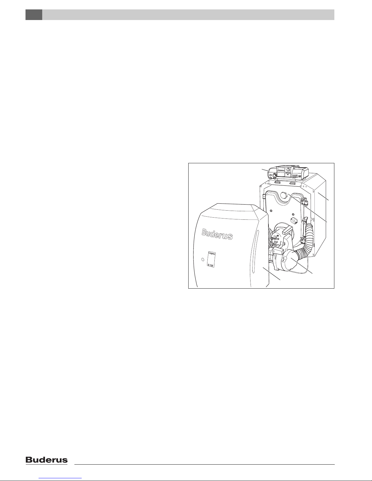
1
Fig. 1 Boiler G125 BE US/CA
1 Control panel
2 Boiler jacket
3 Boiler block with insulation
4 Burner door cover
5 Burner
2
3
5
4
7 747 010 678-01.1RS
6
Logano G125 BE - Specification subject to change without notice.
Page 7
3 Technical Information
3.1 Technical Data less Burner
25 1/2"
23 1/2"
14 1/2"
Technical Information
12 1/4"
3
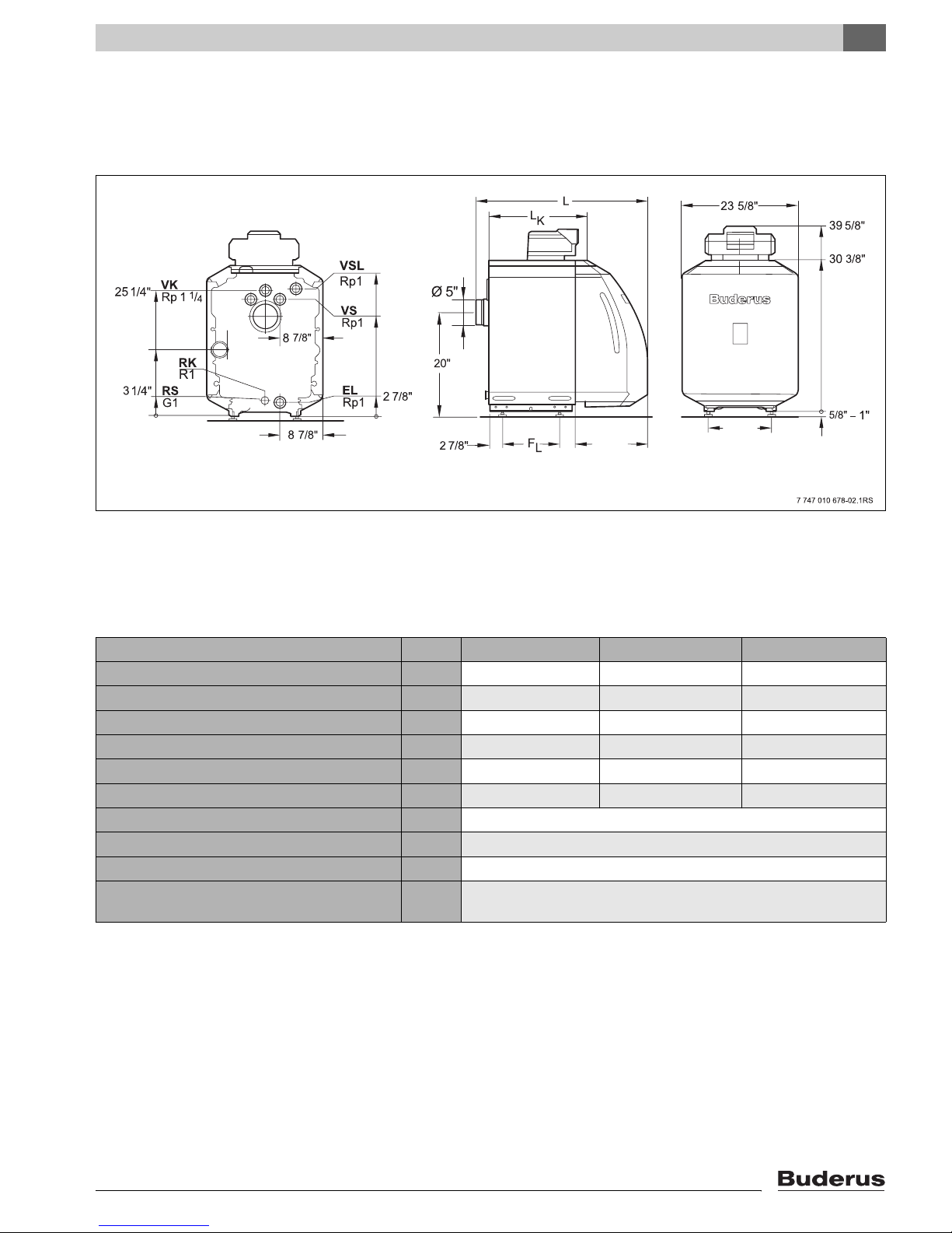
Fig. 2 Dimensions and connections (measurements in inches)
Connections (For Measurements see following tables):
VK = Boiler supply VS = Connection (plugged)
RK = Boiler return RS = Connection (plugged)
EL = Boiler drain (Connection for drain valve) VSL = Connection (plugged)
Boiler Model G125/21-BE G125/28-BE G125/34-BE
Number of boiler blocks 34 5
Heating Capacity (Gross Output) MBtu/hr 72 96 116
Net IBR MBtu/hr 63 83 101
Boiler water content Gal 8.7 10.8 12.9
Fireside volume cu.ft. 1.20 1.75 2.21
Oil firing rate GPH .60 .80 1.0
Fireside pressure drop psi 0.00058 – 0.00145
Permissible max. supply temperature
1
°F 230
Allowable operating pressure psi 58
Maximum Reset High Limit for temperature
s 40
sensor and overheat thermostat (STB)
Table 1 Technical Data for G125 BE less burner
1
High limit (overheat thermostat STB)
Permissible maximum supply temperature = High limit (STB) – 32 °F
e.g.: High limit (STB) = 212 °F, maximum permissible supply temperature = 212 – 32 = 180 °F
Select your high limit (STB setting) according to your local codes and requirements.
Logano G125 BE - Specifications subject to change without notice.
7
Page 8

3
Technical Information
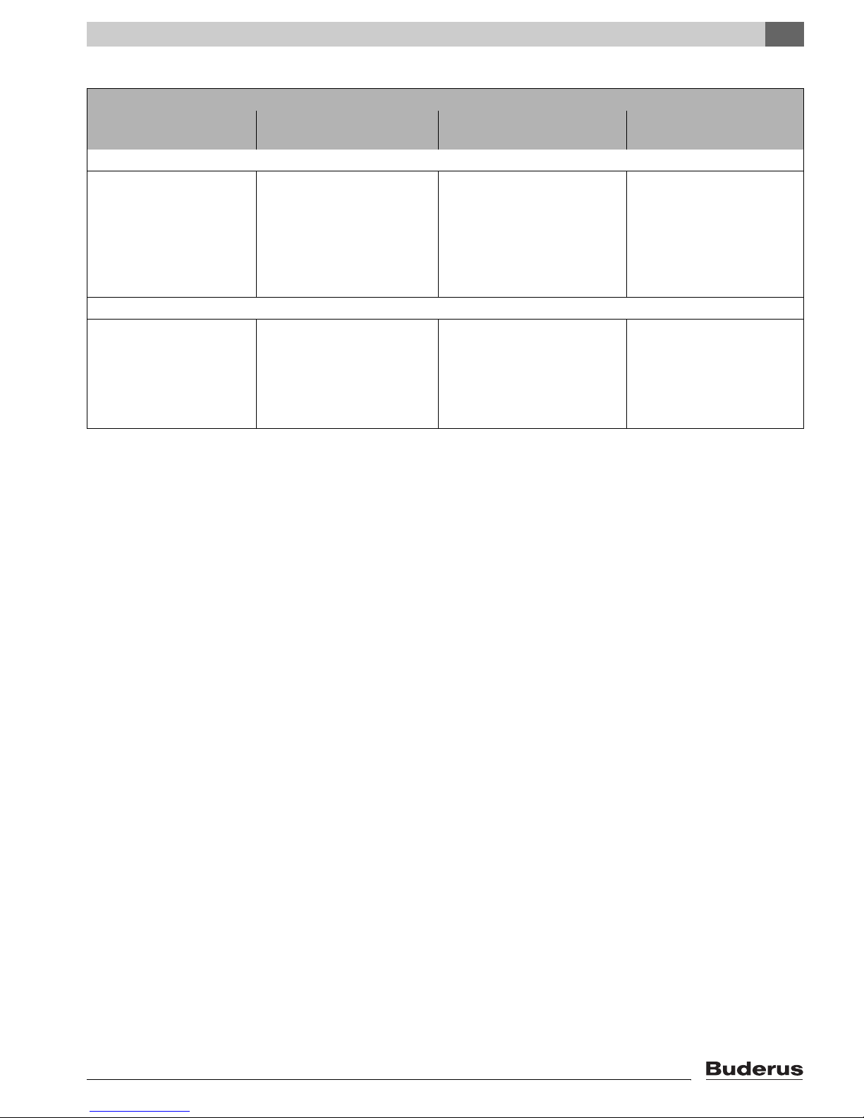
Boiler Model G125/21-BE G125/28-BE G125/34-BE
Total boiler length (L) 34 5/8” 39 3/8” 44”
Boiler block length (LK) 21 1/8” 25 3/4” 30 1/2”
Combustion chanber length 16” 20 1/2” 25 1/4”
Firebox diameter 10 5/8”
Burner door thickness 3 1/2”
Distance between boiler feet (FL) 11 3/8” 16 1/8” 20 7/8”
Dry weight
Table 2 Dimensions, Weight and other Data for G125 BE less burner
1
Weight incl. packaging material approx 6 – 8% more.
1
386lbs 459lbs 513lbs
3.2 Operating Conditions
Maintain the operating requirements listed on the following page for long and trouble free operation of the boiler.
Proper and timely maintenance procedures must be followed.
SYSTEM DAMAGE
CAUTION!
If these operating requirements are not
followed, it can lead to premature failure
can result and cause permanent damage
to the boiler.
z Follow the instructions on the rating la-
bel and those in the manual.
8
Logano G125 BE - Specifications subject to change without notice.
Page 9
Technical Information
3.2.1 General Operating Requirements
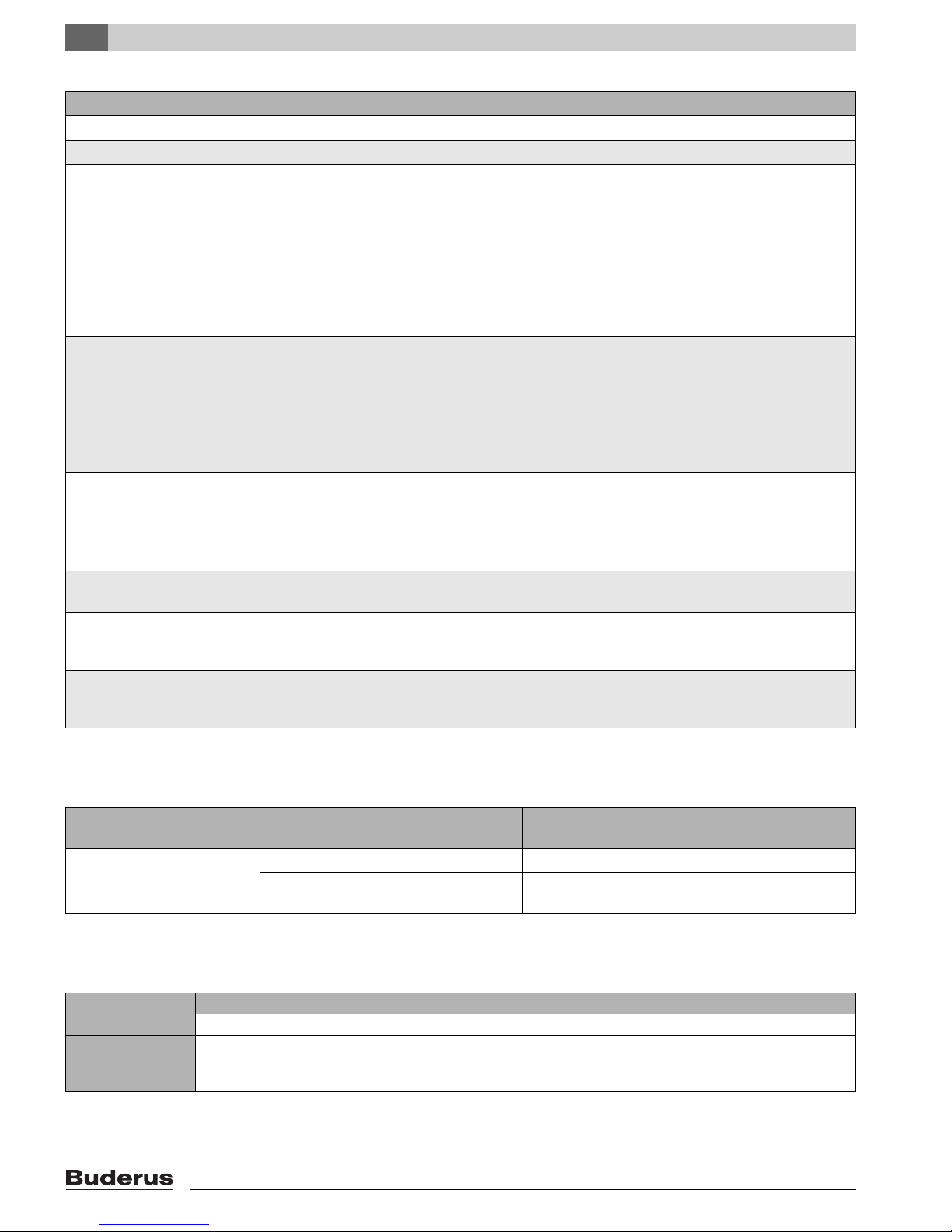
Operating Conditions
Minimum Boiler tempera-
ture
Systems controlled by R2107 controls for outdoor reset operation
No requirements
Operating conditions are met
with R2107 control
150 °F
2
3
Table 3 General Operating Requirements
1
A heating circuit equipped with a motorized mixing valve improves the controllability of that sub-system and is specifically recommended when
requiring different water temperatures.
2
In case the control system has no influence over the flow in a heating circuit (for instance using the Pumplogic feature of the R2107), then one
should achieve a minimum supply temperature of 122 °F within 10 minutes after burner start-up by means of reducing (or interrupting) the water
flow through the boiler.
3
Minimum setting on the adjustable high limit or Aquasmart: During burner operation one should achieve the minimum boiler temperature within
10 minutes after burner start-up by means of flow reduction and one should maintain this temperature.
Boiler Shutdown Boiler Shutdown/
Mixed temperature
Automatic with Logamatic
R2107
No requirement, yet beneficial
with low temperature boiler with
130/113 °F system design
Necessary with:
– Radiant floor applications
– Systems with large water con-
tent > 115 gal/100,000 Btu/hr
Systems controlled by Aquasmart or R2109
Possible, provided the boiler op-
erates after total shut-down for
at least 3 hours.
1
Minimum return temperature
No requirement
Necessary Necessary for:
– Systems with large water
content > 115 gal/100,000
Btu/hr: 130 °F
– Firing with modulating burn-
ers: 130 °F
3
Logano G125 BE - Specifications subject to change without notice.
9
Page 10
3
Technical Information
3.2.2 Requirements for Boiler Room and Surroundings
Operating Conditions Comments – Detailed Information
Boiler room temperature +40 to +104 °F
Relative humidity max. 90 % No condensate or dampness in boiler room.
Dust – No excess amounts of dust should be present in the boiler room, e.g.:
– No sheet rock or construction dust.
The available combustion air can not contain dust or other particles/ use of an air
filter might be needed, e.g.:
– Combustion air from nearby roads with high dust levels.
– Combustion air from nearby production facilities such as chemical plants &
shops.
– Airborne particulates.
Halogenated Hydrocarbons
contamination
Fans, removing air from boiler
room
Animals – The boiler room and especially the air inlet openings for combustion air must be
Fire Protection – Maintain proper clearances to combustible materials as required per local code.
Flood Zone Conditions – Separate the fuel supply and electrical power supply from the boiler during flood
– Combustion air must be free of halogenated hydrocarbons components.
– Eliminate any chemical compound such as paints, lacquers, thinners, clean-
ing agents. If not possible, provide fresh outside air for combustion.
Please observe the following:
– Product information of Buderus catalog.
– Also observe guidelines in K3 chapter of Buderus catalog.
– Avoid forced air removal by mechanical means during boiler operation such as:
– Bathroom exhaust fans
– Dryer
– Air-conditioning equipment
kept free from animals entering by means of grills.
Maintain a minimum distance of 16”. Do not store flammable materials near the
boiler.
conditions. Replace the boiler components such as insulation, electrical and control components afterwards.
Table 4 Boiler room and surroundings
3.2.3 Combustion Air Requirements
Operating Conditions Boiler capacity (combine total boiler ca-
pacity for multiple units)
Two air inlet openings from outside: one top, one near bottom
Table 5 Observe local codes and regulations for combustion air requirements
< 170,000 Btu/hr At least 43 square inch
> 170,000 Btu/hr At least 43 square inch plus 2.5 square inch per 10,000
Btu/hr, if the output is higher than 170,000 Btu/hr.
3.2.4 Fuel Conditions
Country All Countries
Fuel #2 Fuel Oil ASTM D396-05 Type 2
Comments No other fuel may be used with this burner.
Burner requires annual service and cleaning. Verify each time that the complete heating system is in working
order. Defects must be remedied immediately.
Table 6 Permitted fuel types
Cross area required
10
Logano G125 BE - Specifications subject to change without notice.
Page 11
Technical Information
3
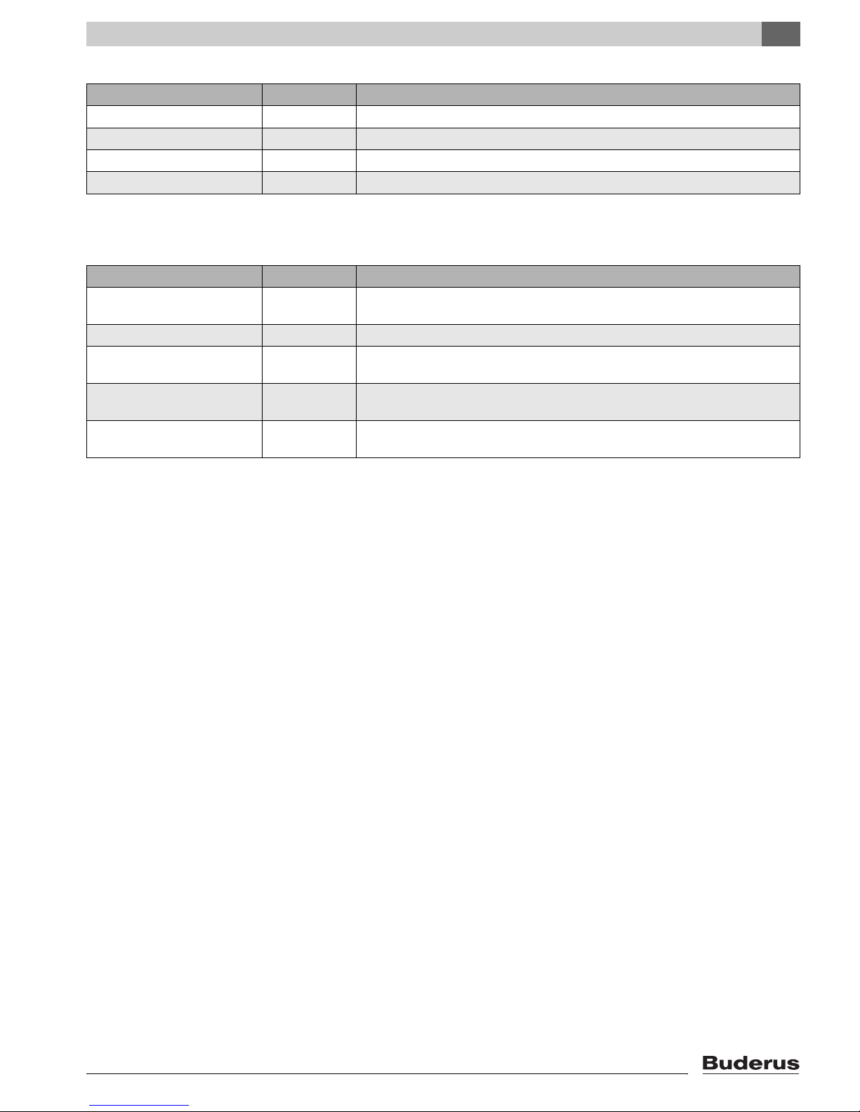
3.2.5 Requirements for Power Supply
Operating Conditions Comments – Detailed Information
Main power supply 120 V Provide proper grounding for equipment and personal protection.
High amp protection 10 A
Frequency 60 Hz
Protection – Group all equipment per local code
Table 7 Power supply
3.2.6 Conditions Pertaining to Piping and Water Quality
Operating Conditions Comments – Detailed Information
Operating pressure (over pressure)
Allowable test pressure 45 – 75 psi
Adjustable temperature limit TR122 – 194 °F
Manual reset high limit 210 °F In combination with Beckett AquaSmart the limit value (210 °F) may not be excee-
Water quality – Initial fill water and make-up water should be potable water type quality. A pH
12 – 58 psi Maximum pressure is 30 psi based on supplied relief valve
ded.
range of 8.2 to 9.5 is desired.
Table 8 Piping and water quality
Logano G125 BE - Specifications subject to change without notice.
11
Page 12
4
Packaging and Components
4 Packaging and Components
z Check the packaging for concealed damage.
z Check the packaging for completeness. Contact your
wholesaler in case of missing parts.
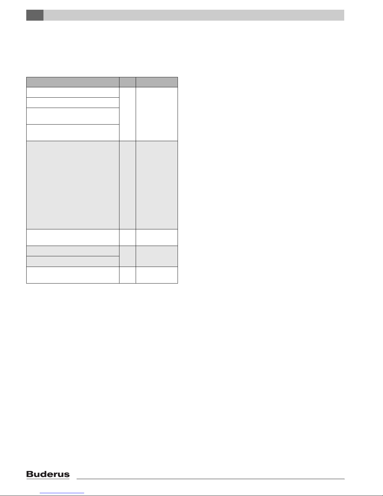
Component Qty Packaging
Boiler block 1 Pallet
Boiler jacket, installed on boiler
Burner door and burner door cover
installed on boiler block
Buderus oil burner mounted on customized burner door
B-Kit-Components:
Supply manifold (1¼" NPT)
30 psi relief valve
(¾") boiler drain
Pressure/temperature gauge
(1¼" NPT × R1¼) conversion nipple
(parallel to NPT)
90°-elbow (1¼" NPT)
90°-elbow (¾" NPT)
Burner mounting studs and washers
Screw in feet
14Plastic pack-
aging with boiler
Control panel, alternative Aquasmart control (ordered separately)
Tigerloop oil filter 1 included with
Taco 007 circulator pump w/flanges
Technical documents 1 Plastic pack-
Table 9 Packaging and components
Cardboard
box
boiler package
aging w/boiler
12
Logano G125 BE - Specifications subject to change without notice.
Page 13
5 Moving the Boiler
This chapter describes how to move the boiler.
SYSTEM DAMAGE
due to bumps.
CAUTION!
z Protect the boiler from bumps and
rough treatment.
NOTICE
z Protect the boiler from connections
from damage and dirt, when the boiler
is not installed immediately.
NOTICE
Please dispose of the packaging in an environmentally friendly fashion.
Moving the Boiler
5
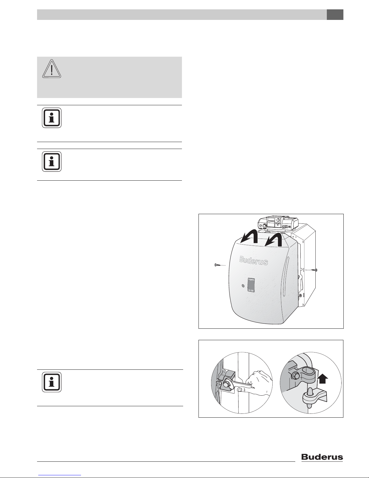
5.1 Reducing Boiler Weight for Transportation
One can reduce boiler weight by removing the front cover and burner door itself.
z Remove the screws holding the front cover in place.
z Lift up the front cover slightly and remove.
z Disconnect burner cable from burner control before
removing the burner door.
z Open burner door by removing the two burner door
bolts.
z Lift burner door from hinges.
NOTICE
Fig. 3 Removing the front cover
z Protect the burner door and the burner
tube from damage and dirt when the
burner door is removed from the boiler.
Logano G125 BE - Specifications subject to change without notice.
Fig. 4 Removal of burner door
13
Page 14
5
Moving the Boiler
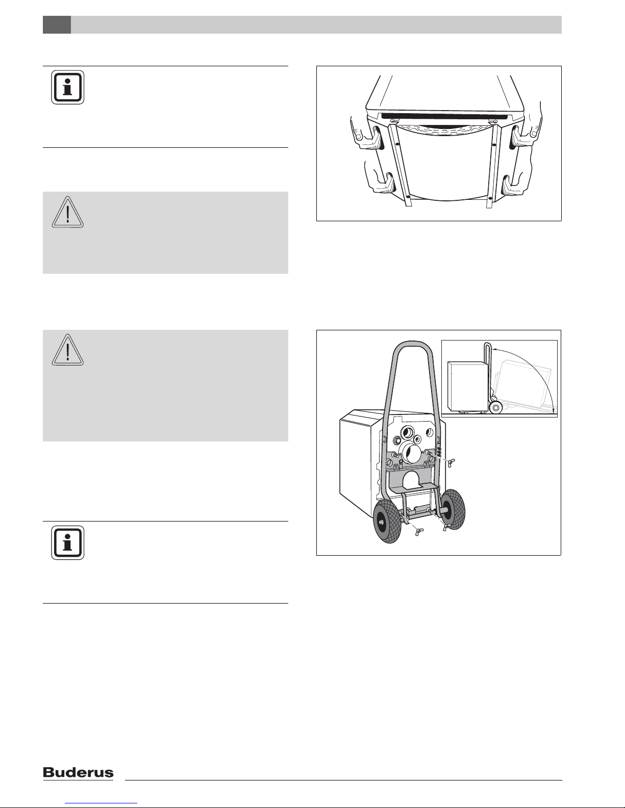
5.2 Lifting and Carrying the Boiler
NOTICE
The boiler is secured to the pallet with two
bolts.
z Remove the bolts from pallet before
lifting the boiler.
The boiler can be picked up at the hand grips located
along the lower jacket panels.
BODILY DANGER
due to carrying of heavy loads.
CAUTION!
z Lift and carry the boiler with at least
two people at the designated hand
grip positions.
5.3 Moving the Boiler with the Boiler Cart
BODILY DANGER
if the product is not properly secured to
CAUTION!
z Lift up the boiler from the rear side by using moving
equipment (e.g. Buderus card or other dolly).
z Secure the boiler to the cart.
z Move the boiler to the job location.
the cart.
z Use proper moving equipment such as
the Buderus cart or other dolly.
z Secure the boiler to the cart and move
the boiler to the job location.
Fig. 5 Lifting and carrying the boiler
NOTICE
By tipping the cart you can install the boiler feet (Î Chapter 6.3, page 17).
You can order a Buderus cart from your
local wholesaler.
14
Fig. 6 Moving the boiler with a Buderus cart
Logano G125 BE - Specifications subject to change without notice.
Page 15
6 Placing the Boiler
This chapter discusses how to place the boiler in the
boiler room.
SYSTEM DAMAGE
due to freezing temperatures
CAUTION!
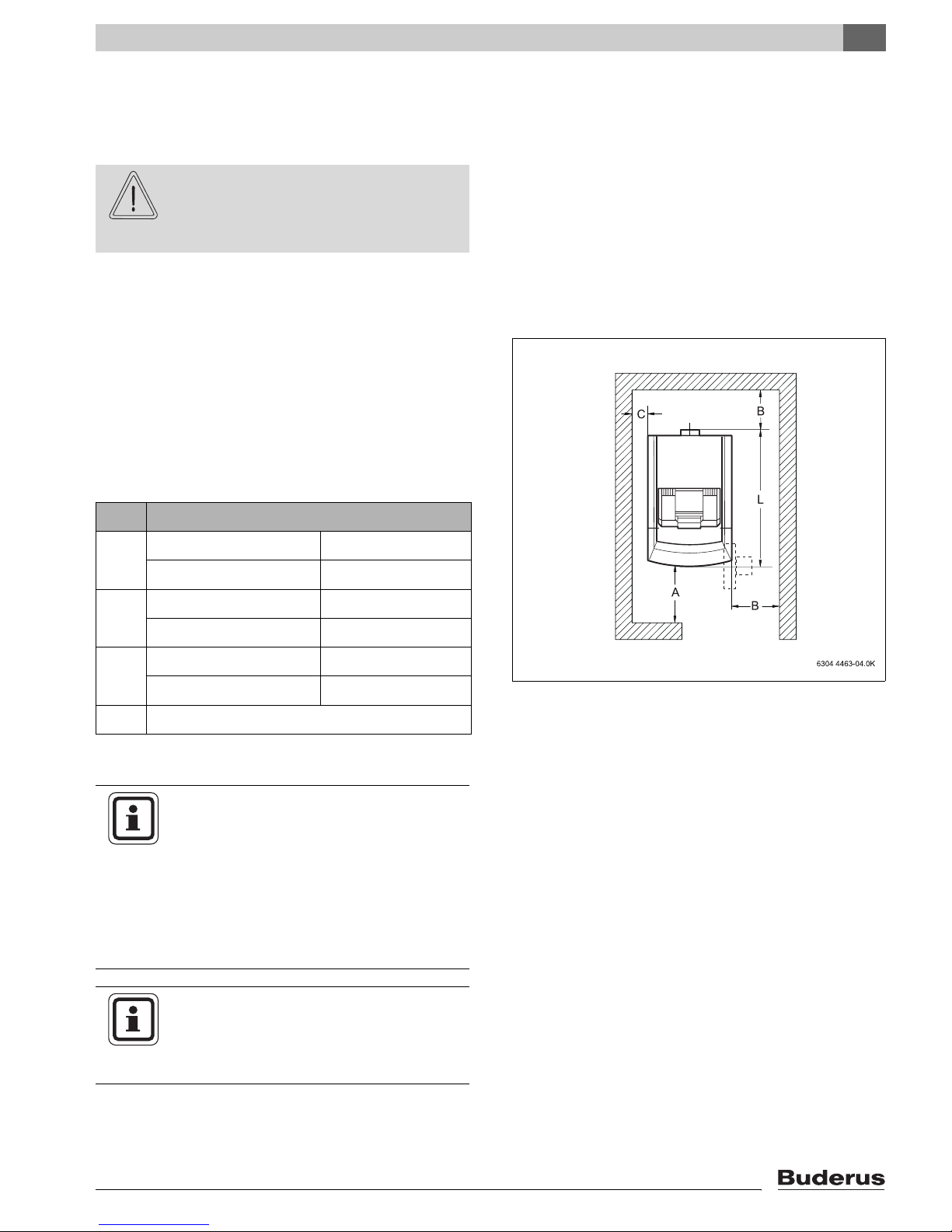
6.1 Clearances
Position the boiler while observing the clearances in
(Î Fig. 7). Access to the boiler is reduced when reducing these clearances.
The boiler foundation must be level and sufficiently
strong.
The burner door is factory installed right swinging. Youcan reverse the door swing in the field.
z Place the boiler in a frost free room.
Placing the Boiler
6
Distance
A Recommended 51 1/8"
minimum 39 3/8"
B Recommended 27 1/2"
minimum 15 3/4"
C Recommended 15 3/4"
minimum 3 7/8"
L see Chapter 3 „Technical Information“
Table 10 Recommended and minimum clearances
(Measurement in Inches)
NOTICE
Smaller clearances must abide with state
and local code. The boiler is approved for
6" side clearances. A minimum distance
of 18" to combustible materials must be
maintained per NFPA 31.
Floor material must comply with
NFPA 31.
Fig. 7 Clearance dimensions for G125 boilers
NOTICE
Observe required distances to other components such as water piping, venting
and other components.
Logano G125 BE - Specifications subject to change without notice.
15
Page 16
6
Placing the Boiler
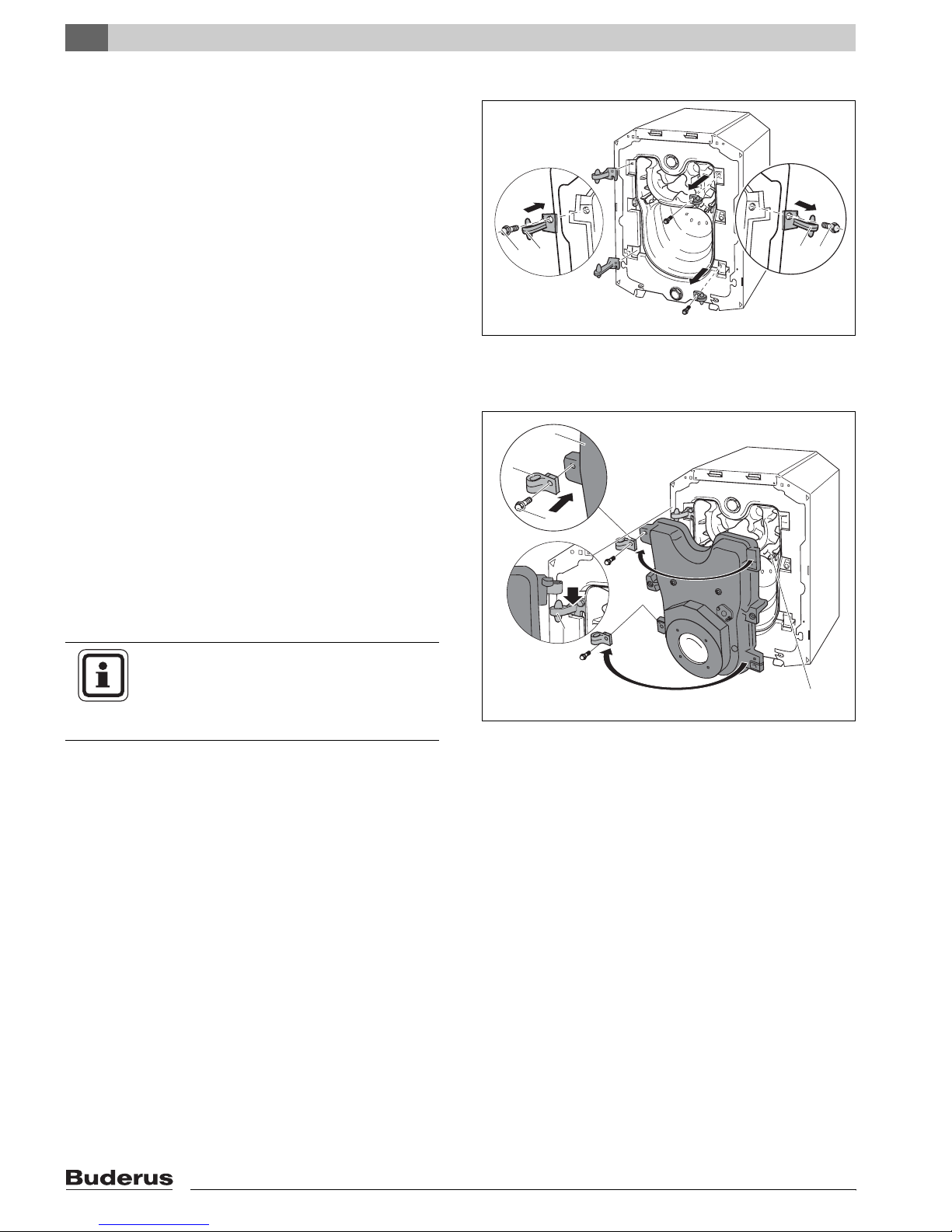
6.2 Reversing the Burner Door Swing
The burner door hinges are factory installed on the right
handside the burner door swings to the right. You can
adjust the hinges so that the burner door swings to the
left in the field.
Note: the front panel must first be removed.
(Î Chapter 5.1, page 13).
z Remove burner door (Î Chapter 5.1, page 13).
z Remove hex head bolts of burner door hinges and re-
move hinges.
z Install the hinges on the left side of the boiler with the
hex head bolts.
z Remove the eyelets from the burner door by remov-
ing the hex head bolts.
z Locate and secure with hex head bolts these eyelets
to the left side of the burner door.
z Hang the burner door on the hinges.
z Check to make sure that the flue baffle plates are
horizontally in the boiler (Î Chapter 8.3, page 40).
z Secure the burner door with the burner door bolts.
Make sure to tighten the burner door bolts evenly
with about 7.5 ft-lbs torque.
NOTICE
When reversing the swing of the burner
door, make sure to remove the burner cable and oil line from the burner first.
2
1
Fig. 8 Reversing burner door (boiler block)
1 Hex head bolts for hinges
2 Door hinges
3
2
1
4
Fig. 9 Reversing burner door (on burner door)
1 Hex head bolts for door eyelets
2 Door eyelet
3 Burner door
4 Door hinges
5 Flue baffles
1
2
5
16
Logano G125 BE - Specifications subject to change without notice.
Page 17
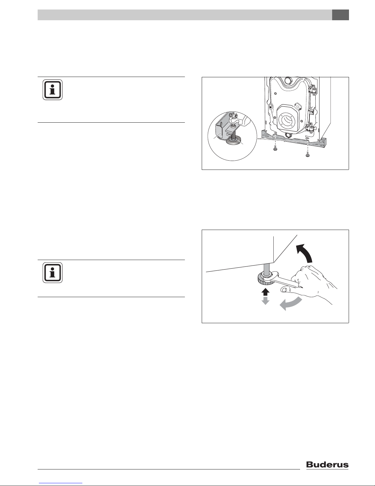
6.3 Installation of boiler Feet (Components of B-Kit)
You can level the boiler using the screw-in boiler feet, so
that air can not collect in the boiler.
Requirement: remove front panel from boiler
(Î Chapter 5.1, page 13).
NOTICE
When installing a G125 BE boiler on top
of a horizontal Buderus DHW indirect
tank, do not use the boiler feet on the boiler, but rather use the feet to level the tank.
z Tip the boiler slightly using the boiler cart
(Î Chapter 5.3, page 14) or put a piece of wood under one side.
z Screw in the boiler feet 1/4" – 3/8".
1
Placing the Boiler
6
2
z Level the boiler.
6.4 Placement of the Boiler
z Bring the boiler to its final location.
z Put a level on the boiler and adjust boiler feet to level
the boiler.
NOTICE
z Protect the boiler connections from
dust and debris, if the boiler will not be
connected right away.
Fig. 10 Installation of boiler feet
1 Boiler rail
2 Boiler feet
Fig. 11 Leveling the boiler
Logano G125 BE - Specifications subject to change without notice.
17
Page 18
7
Boiler Installation
7 Boiler Installation
7.1 Installation of Venting Systems
This chapter describes the installation of the venting
system and the combustion air supply system for the
G125 BE boiler.
Following venting options are available:
Venting system Comment Draft Combustion air Chapter
Masonry chimney (no liner) Barometric
Masonry chimney
w/ 5" liner
Vertical vent 5" 7.1.1.3, Page 21
Side wall Sealed vent Positive Outside air only 7.1.2, Page 22
Table. 11Venting options
damper
required
Negative Outside air or room air 7.1.1.1, Page 19
7.1.1.2, Page 20
WARNING!
DANGER TO LIFE
from toxic flue gases.
z Never connect more than one appli-
ance to a venting system - regardless of
vertical or horizontal venting.
z Common venting of appliances can
cause property damage and put life at
risk.
z Chimney liners must be a single contin-
uous piece inside an existing chimney
and can not have any connections inside the chimney chase.
z The venting system shall not be routed
into, through, or within any other vent,
such as an existing masonry or factorybuilt chimney that is used to vent any
other appliance.
z Always follow vent manufacturer’s in-
structions.
NOTICE
WARNING!
FIRE DANGER
from insufficient clearance between vent
system components and combustible surfaces.
z Maintain 18" clearance to combustible
surfaces when using galvanized or
stainless pipe in vertical or horizontal
venting.
z Maintain 1" clearance to combustible
surfaces when using flexible oil vent for
horizontal venting.
z Both the Aerocowl (AT-4) exhaust ter-
mination and Fields (FT-4) concentric
exhaust/intake terminations are approved with zero clearance to combustible surfaces.
NOTICE
The boiler installation must be performed
by a qualified installer in accordance with
regulations put forth in NFPA-31 Installation of Oil-Burning Equipment. The installation must comply with all local and
national codes, regulations and authorities
having jurisdiction regarding the installation of oil fired boilers.
For Canada refer to the guidelines of
CSA/B139 Installation Codes.
18
z Avoid excessively long venting sys-
tems and keep the number of elbows to
a minimum.
Logano G125 BE - Specifications subject to change without notice.
Page 19
NOTICE
Due to tight construction of modern
homes, Buderus recommends drawing
combustion air from outdoors. The boiler is
factory prepared for connecting 4" rigid
pipe ducted directly to the increaser at the
rear of the boiler. For further directions
Î Chapter 7.2, page 28.
Except for direct venting, and provided
ample combustion air is available in the
boiler room, combustion air can also be
drawn from the room (Î Chapter 7.2,
page 28 for details).
NOTICE
For Canada the G125 BE is approved
without a Blocked Vent Switch.
Should local authorities require a Blocked
Vent Switch Î Chapter Fig. 63, page 68.
Boiler Installation
7
7.1.1 Vertical Venting Systems
The G125 BE boiler can be vented vertically using an
existing masonry chimney or a factory built All-Fuel or Lvent chimney.
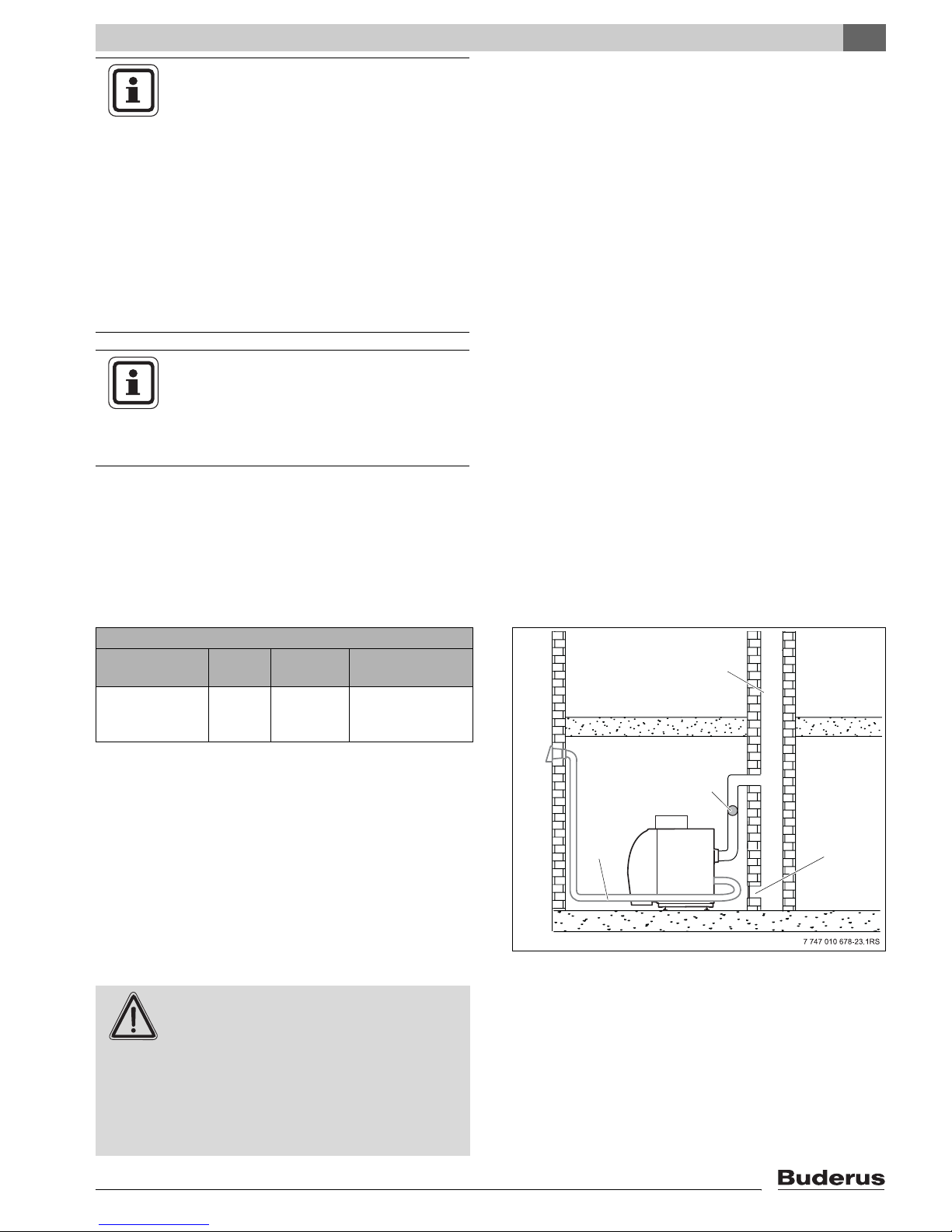
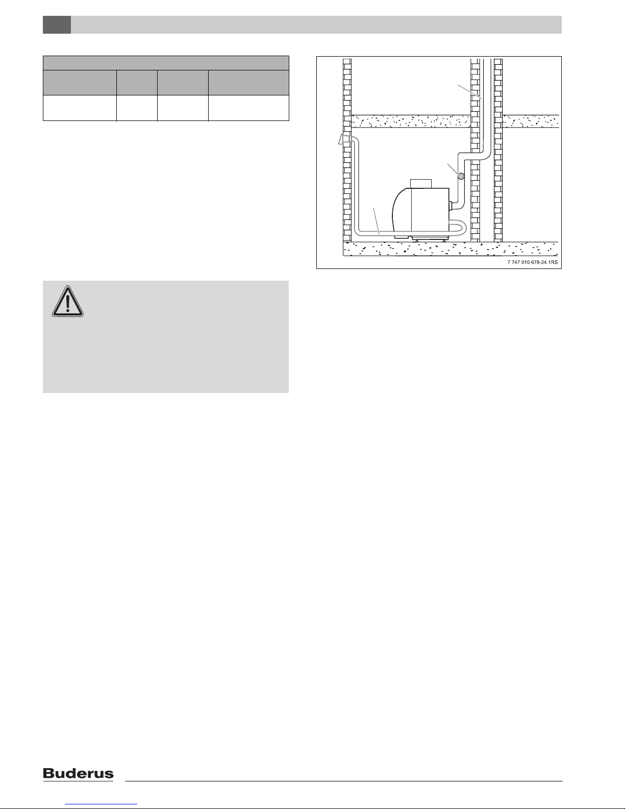
7.1.1.1 Masonry Chimney
Venting system: Masonry Chimney
Comment Draft Combus-
tion air
Barometric
damper
required
Negative Outside air
or room air
Max. vent length
60 ft.
Refer to NFPA 31 for requirements on chimney venting.
Old, cold or over-sized chimneys require the use of an
approved 5" chimney liner (Î Page 20).
The maximum vent length of a masonry chimney is 60 ft.
A masonry chimney is operated under slight negative
pressure, and requires a barometric damper.
z Follow damper manufacturer’s instructions as to
placement.
z Adjust draft for negative 0.02 – 0.04" W.C.
DANGER TO LIFE
from toxic flue gases.
WARNING!
z Verify that all vent pipe connections
have been installed properly.
1
2
4
Fig. 12 Masonry chimney installation
1 Chimney
2 Barometric damper
3 Clean-out
4 Horizontal air connection for combustion air
(optional, see 7.2)
3
z Have the entire venting system cleaned
and inspected annually by a qualified
service company.
Logano G125 BE - Specifications subject to change without notice.
19
Page 20
7
Boiler Installation
7.1.1.2 Chimney with 5" Liner
Venting system: Chimney with 5" Liner
Comment Draft Combus-
tion air
Barometric
damper required
Negative Outside air
or room air
Max. Vent length
60 ft.
Install liner according to manufacturer’s instructions.
Follow all applicable local and national codes and regulations.
The maximum vent length of 5" liner in a masonry chimney is 60 ft.
The 5" liner in a chimney is operated under slight negative pressure, which requires a barometric damper.
z Follow damper manufacturer’s instructions as to
placement.
1
2
3
z Adjust draft for negative 0.02 – 0.04" W.C.
DANGER TO LIFE
from toxic flue gases.
WARNING!
z Verify that all vent pipe connections
have been installed properly.
z Have the entire venting system cleaned
and inspected annually by a qualified
service company.
Fig. 13 5" Chimney liner installation
1 5" Chimney liner
2 Barometric damper
3 Horizontal air connection for combustion air
(optional, see 7.2)
20
Logano G125 BE - Specifications subject to change without notice.
Page 21
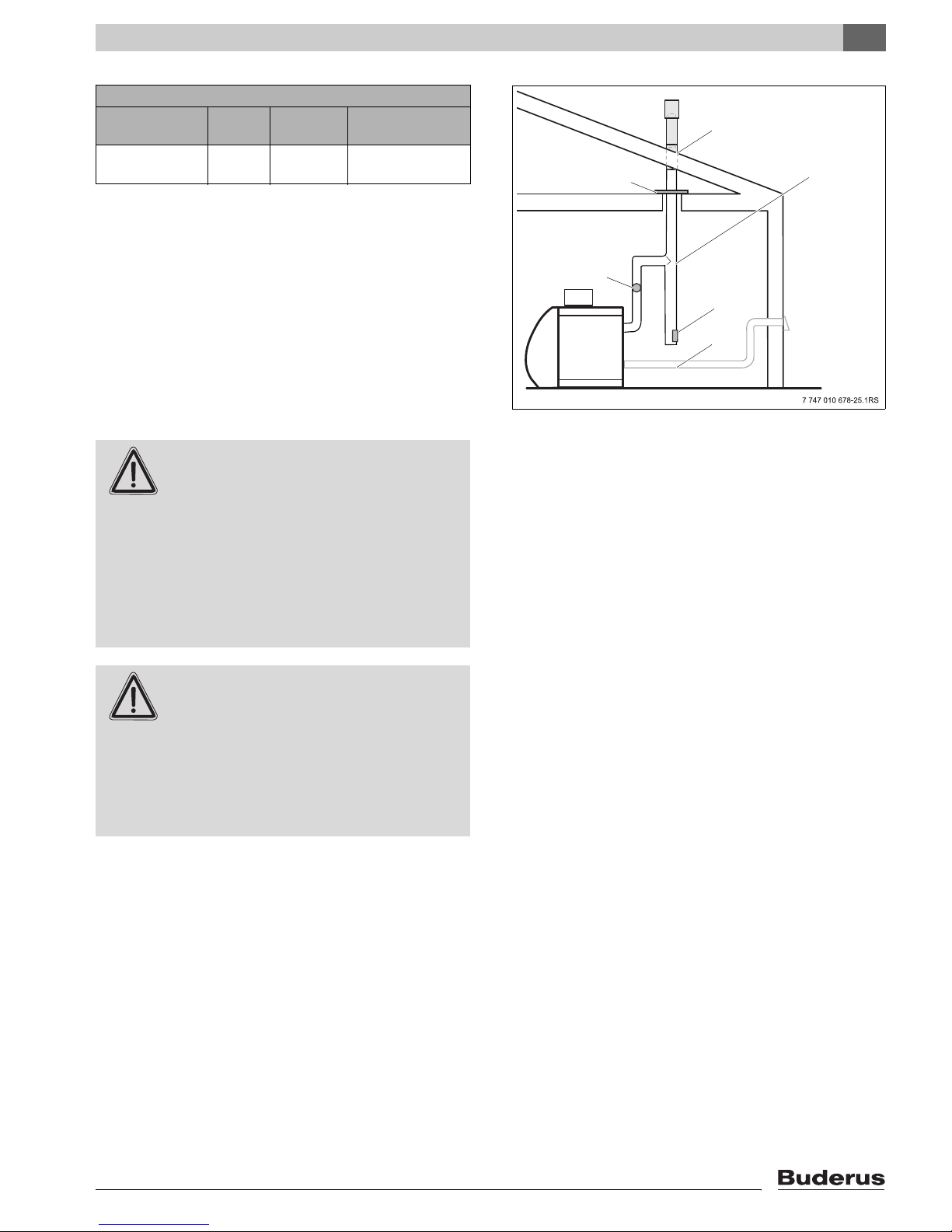
7.1.1.3 Vertical Vent
Venting system: 5" Vertical Vent
Comment Draft Combus-
tion air
Barometric
damper required
Negative Outside air
or room air
Max. Vent length
60 ft.
Extend the vertical vent pipe sufficiently far above the
roof per NFPA 31. Follow all applicable local and national codes and regulations.
Boiler Installation
7
1
2
3
The maximum length of the vertical 5" venting system is
60 ft.
The 5" vertical venting system operates under a slight
negative pressure, which requires a barometric damper.
z Follow damper manufacturer’s instructions as to
placement.
z Adjust draft for negative 0.02 – 0.04" W.C.
DANGER TO LIFE
from toxic flue gases.
WARNING!
z Vertical vent pipe must have an ap-
proved fire stop at each ceiling penetration and the stack must be properly
supported at its base.
z Each venting section must be support-
ed at each elbow and at least every 48"
of straight pipe.
DANGER TO LIFE
from toxic flue gases.
WARNING!
z Verify that all vent pipe connections
have been installed properly.
4
5
6
Fig. 14 Vertical venting system installation (supports are not
shown for clarity)
1 Roof Penetration
2 Fire stop
3 All-Fuel or L vent flue pipe
4 Barometric Damper
5 Clean-out
6 Horizontal air connection for combustion air
(optional, see 7.2)
z Have the entire venting system cleaned
and inspected annually by a qualified
service company.
Logano G125 BE - Specifications subject to change without notice.
21
Page 22
7
Boiler Installation
7.1.2 Horizontal Venting
Venting system: Side wall
Comment Draft Combus-
tion air
Sealed vent Positive Outside air
only
Max. Vent length
20 ft.
The maximum length of the direct vent system is 20 ft. of
linear pipe including 3 x 90° elbows. With 4 elbows the
maximum pipe length is 10 ft.
The following two direct vent terminations are approved
with the G125 BE, and are available for purchase from
your Buderus supplier.
Both exhaust terminations are approved for use with two
different exhaust vent pipe options.
– Option 1:
Flexible, insulated 4" stainless steel oil vent. The insulated oil vent is rated for 1" clearance to combustibles. Wrap the adapters with 3" of ceramic wool
covered with foil tape or sheet metal to maintain 1"
clearance. For installation instructions Î Chapter
„7.1.2.6 Installation of Insulated Flexible Oil Vent“,
page 26.
– Option 2:
Standard, 26 gauge galvanized 4" vent pipe. Maintain 18" clearance to combustibles with galvanized
vent pipe (Î Chapter „7.1.2.7 Installation of Galvanized Vent Pipe“, page 27).
NOTICE
Horizontal vent systems operate under
positive pressure, which requires all
seams to be sealed. Use high temperature
silicone (500°F rated, G.E. 106 or equivalent) to seal any joints, screw penetrations,
or combustion test holes, and seal at each
pipe connection and all joints on adjustable elbows. Refer to 7.1.2.2 for details.
NOTICE
Installations in Canada less than 7 ft.
above ground are required to have a
cage/screen over the termination to prevent injury from touching hot surfaces.
Fig. 15 Aerocowl (AT-4) and Concentric (FT-4) termination
22
Logano G125 BE - Specifications subject to change without notice.
Page 23

7.1.2.1 Location of Exhaust Wall Termination
3'
1,5'
Boiler exhaust
Boiler Installation
Boiler exhaust
7
Forced air
at least 1 ft. above grade
Fig. 16 Minimum clearance for termination
Exhaust terminal
must be at least 3 ft. above
any forced air inlet within 10 ft.
The location of the wall termination is one of the
most important aspects of a direct-vent installation.
In addition to the minimum clearances of terminations shown in Fig. 16, observe the following rules:
1. Both the intake and exhaust terminations must
be located on the same outside wall in order to
balance wind pressure effects.
2. Wall terminations shall not be facing the direction of prevailing winds.
3. The exhaust terminal must be located such that
flue gases will be freely dispersed without reentering the building.
4. Exhaust terminal shall be at least 2 ft. from
adjacent buildings, and flue gases shall not be able
to enter adjacent buildings.
5. The exhaust terminal shall be at least 7 ft. above
grade when above public walkways. Ensure that
freezing condensate does not lead to hazardous
conditions on walkways.
6. The exhaust terminal shall never be located underneath porches or crawl spaces, alcoves, or other
building features that prevent dispersing flue
gases.
Gravity air inlet
inlet
less than 2 ft. from outside corners.
8. The exhaust terminal shall be located at least 3 ft.
above any forced air inlet within 10 ft. horizontally.
9. The exhaust terminal shall never be less than 4 ft.
below, 1 ft. above, or 4 ft. horizontally from any
door, window, or gravity air inlet into the building.
10. The exhaust terminal shall be at least 1 ft. above
grade and snow line, and where it is not susceptible to blockage from debris, leaves or falling snow
or ice.
11. A ½" wire-mesh screen at the exhaust terminal
must be maintained in good working order.
12. The exhaust terminal shall terminate at least 3 ft.
from any other building opening, oil tank vent or oil
tank fill inlet, and 6 ft. from any gas service regulator vent outlet.
13. Select the point of wall penetration maintaining a
minimum slope of ¼" per foot toward the termination on the last horizontal pipe section. The wall termination assembly must also slope ¼" per foot
toward the outside to drain possible condensate
from the venting system.
7. The exhaust terminal shall never be located less
than 3 ft. from inside building corners, and never
Logano G125 BE - Specifications subject to change without notice.
23
Page 24

7
Boiler Installation
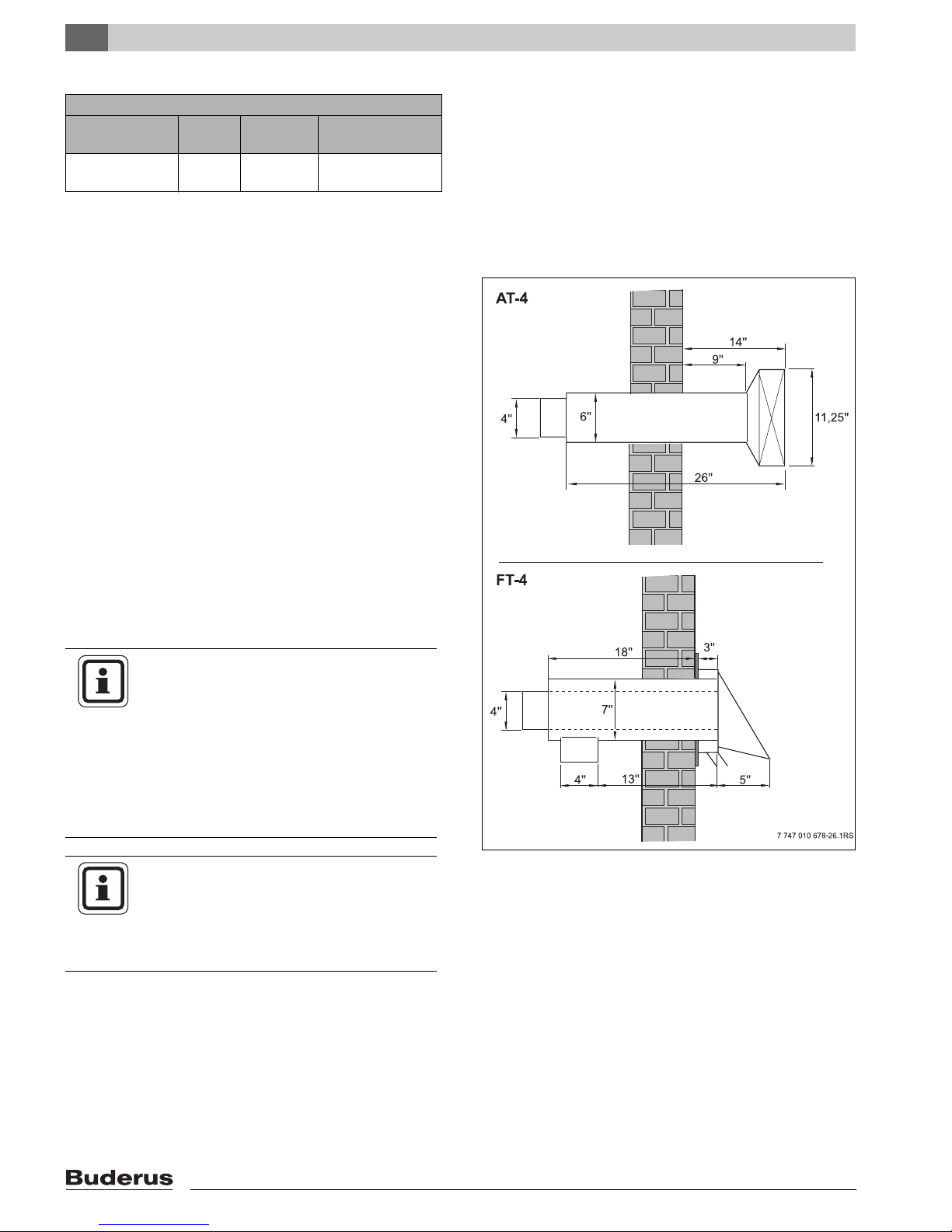
7.1.2.2 Installation of Aerocowl exhaust termination
(Part No. AT-4)
z Follow guidelines in section 7.1.2.1 regarding the rel-
ative position of the exhaust and terminal.
z Follow manufacturer’s installation guidelines of the
AT-4.
This system consists of a 4" air intake hood, a 5" x 4" reducer and a 26½" long, insulated Aerocowl exhaust termination. This termination has a zero clearance rating to
combustibles. Do not install the vacuum relief damper
(“not needed”).
z Cut a 6" round opening in the outside wall at the se-
lected location. Apply silicone caulking to the backside of the outer face plate and secure it to the
outside wall.
z Insert the Aerocowl termination from the outside up
to the outer wall stop. Ensure slope of ¼" per foot to
outside.
z Slide inner plate on the termination up to the inside
wall, tighten the gear clamp and secure the inner
plate to the wall.
z For Aerocowl AT-4 installations in Canada less than
7 ft. above ground, install a cage/screen over the ter-
Fig. 17 Aerocowl exhaust termination (Part No. AT-4) and
mination to prevent injury from touching hot surfaces.
7.1.2.3 Installation of the concentric Fields termination (FT-4)
z Follow manufacturer’s installation guidelines of the
FT-4.
This system consists of a 5" x 4" reducer and a zero
clearance concentric combination intake/exhaust termination with a 4" provision for fresh air intake piping. Do
not install the vacuum relief damper (“not needed”).
z Cut a round 7" diameter opening in the outside wall
at the selected location.
z Remove the 4" air intake collar from the termination
assembly.
z Apply silicone caulking to the back side of the wall
face plate. Insert the concentric termination from the
outside.
z Ensure slope of ¼" per foot to outside. Secure the
face plate to the outside wall.
separate air intake hood
z Reinstall the 4" collar.
24
Fig. 18 Combination air intake/exhaust termination (Part No.
FT-4)
Logano G125 BE - Specifications subject to change without notice.
Page 25

7.1.2.4 Sealing of the Vent Pipe
Boiler Installation
7
DANGER TO LIFE
from toxic flue gases.
WARNING!
The discharge side of the direct vent combustion system operates under positive
pressure.
z It is of vital importance to seal all joints
and screw penetrations using high temperature silicone (rated for 500°F, G.E.
106 or equivalent) to prevent leakage of
flue gases into the building.
z The venting system shall never be
pierced under any circumstances after
initial installation. Combustion measurements shall be taken at the exhaust
termination and/or overfire. The
breeching can be pierced for testing as
long as the hole is sealed airtight with a
bolt, washers and high temperature silicone.
7.1.2.3 General Guidelines for Vent Pipe Installation
CAUTION!
DANGER OF FIRE
from combustible material or liquid.
z Establish a safe clearance between
the vent termination and the combustible material per NFPA 31.
The minimum clearance are:
– galvanized vent pipe 18",
– insulated oil vent pipe 1"
The minimum clearances compared to the
boilerÎ Chapter 6.1, page 15.
Maintain a minimum slope of ¼" per foot toward the termination on the last horizontal vent pipe section.
z The wall termination assembly must also slope ¼"
per foot toward the outside to drain possible condensate from the venting system.
z Slope all other horizontal pipe runs ¼" per foot to-
ward the boiler.
z Avoid any dips in the piping, particularly when using
the flexible insulated stainless steel oil vent.
DANGER OF LIFE
from toxic flue gases.
WARNING!
z Never install a barometric damper into
the horizontal direct vent exhaust piping.
z Verify that after system installation, all
vent pipe connections have been installed properly.
z Check all seams and joints for gas
leaks. Correct as necessary.
z Have the entire venting system cleaned
and verified annually by a qualified service company.
Logano G125 BE - Specifications subject to change without notice.
25
Page 26

7
Boiler Installation
7.1.2.6 Installation of Insulated Flexible Oil Vent
z Apply a ¼" wide bead of high temperature silicone all
around the boiler vent connection 1" from the end.
z Install 5" to 4" reducer on boiler vent connection. Se-
cure properly with a clamp.
z Carefully measure the required length of vent pipe.
Cut to length with a hacksaw allowing for the two end
adapters in your measurement.
z Apply a small bead of high temperature silicone to
the outside of the oil vent ends.
z Twist end adapters to each end of the oil vent. Turn
adapters counter clockwise. Engage the outer cover
of the adapter evenly over the exterior of the vent
pipe. Turn the adapter until the vent pipe interior
seats evenly against the expanded teflon gasket of
the end connector.
z Secure adapters to the vent pipe with the provided
clamps.
z Apply a ¼" wide bead of high temperature silicone all
around at the 5" x 4" boiler reducer and wall termination connection.
z Slide adapters on to reducer and wall termination
pipe all the way. Tighten with clamps.
z Support the flexible vent pipe at regular intervals with
brackets or hangers.
z Maintain a 1/2" rise per foot on horizontal runs sloped
to outside.
NOTICE
With the installation:
– Avoid any sag in the pipe.
– Do not bend pipe excessively. Slope
termination to outside.
– Wrap 3" ceramic insulation around
adapter near termination and secure
with sheet metal or foil tape and hose
clamps to maintain 1" clearance.
Fig. 19 Boiler exhaust pipe
26
Logano G125 BE - Specifications subject to change without notice.
Page 27

7.1.2.7 Installation of Galvanized Vent Pipe
Boiler Installation
7
z Apply a ¼" wide bead of high temperature silicone
(500°F rated silicone, G.E. 106 or equivalent) all
around the boiler vent connection (breech) 1" from
the end (Î Fig. 19, page 26).
z Install 5" to 4" reducer on boiler vent connection. Se-
cure properly with a clamp.
z The maximum length of the direct vent system is 20
ft. of linear pipe plus a maximum of 3 x 90º elbows.
With 4 elbows the maximum pipe length is 10 ft. Use
high temperature silicone to seal any joints, screw
penetrations, or combustion test holes, as well as
seal at each pipe connection and all joints on adjustable 90º elbows.
NOTICE
Once the entire venting system is installed, make sure all joints are secure
(Î as well as Chapter „7.1.2.4 Sealing of
the Vent Pipe“, page 25).
NOTICE
Installations in Canada less than 7 ft.
above ground are required to have a
cage/screen over the termination to prevent injury from touching hot surfaces.
WARNING!
HEALTH DANGER
z When using galvanized vent pipe a
proper protection (e.g. screen) at the
wall termination has to be installed. Follow also local codes.
WARNING!
CAUTION!
DANGER TO LIFE
from toxic flue gases.
z All seams and joints of the exhaust
venting must be inspected for flue gas
leaks.
z Have the entire venting system cleaned
and inspected annually by a qualified
service company.
BOILER DAMAGE
from condensation.
When using galvanized vent pipe the flue
gas temperature at the boiler breech must
exceed 300°F in order to avoid condensation. If less than 300°F are measured, the
flue gas temperature will have to be raised
by removal of 2 or more baffles
(Î Chapter 8.8, page 42).
This notice is not applicable if stainless
steel vent pipe is being used instead of galvanized pipe.
Logano G125 BE - Specifications subject to change without notice.
27
Page 28

7
Boiler Installation
7.2 Installation of Combustion Air Supply System
BOILER DAMAGE AND SYSTEM
PROBLEMS
CAUTION!
Due to missing or insufficient openings for
combustion air.
Sufficient openings for combustion air and
ambient air are required.
Insufficient air flow in the boiler room can
lead to temperature rise, with a potential
for consequential property damage.
Insufficient combustion air can result in
poor burner performance and lead to service calls.
z Ensure that primary and secondary air
openings are of sufficient size, and are
not closed off or reduced in size.
z The boiler can not be placed in opera-
tion if such deficiencies have not been
corrected.
z Make the equipment owner aware of
the situation.
To ensure adequate combustion air supply for the boiler
system, follow the guidelines of the NFPA 31, and observe all local and national codes and regulations.
CAUTION!
WARNING!
BOILER DAMAGE
from contaminated combustion air.
z Never place chlorine containing clean-
ing agents, and hydrocarbon based
chemicals near the boiler (e.g. spray
cans, solvents, cleaning agents, paint,
glue).
z Avoid generation and accumulation of
large amounts of dust.
NOTICE
When contamination of combustion air is
expected (such as installations near swimming pools, dry cleaning operations or hair
salons), Buderus strongly recommends
using fresh air ducted directly from the outside to the boiler.
DANGER OF FIRE
from flammable material and liquids.
z Do not store flammables or other liq-
uids in the vicinity of the boiler.
For Canada refer to the guidelines of CSA/CGA-B149.1
and 2 Installation Codes.
28
Logano G125 BE - Specifications subject to change without notice.
Page 29

7.2.1 All air drawn from inside the building
The G125 BE boiler has been approved for operation
drawing all combustion air from the room, provided the
installation meets the requirements of NFPA 31, and the
boiler is NOT vented horizontally.
7.2.2 All air drawn from outdoors
The boiler has been approved for operation drawing all
combustion air from the outside, provided the combustion air intake system meets the following requirements.
The combustion air shall be directly delivered to the rear
of the boiler via 4" ducting.
z Make an opening in the outside wall for wall termina-
tion.
z Use 4" rigid galvanized pipe or 4" flexible metal pipe.
z The maximum length of the fresh air piping must nev-
er exceed 100 ft. Reduce by 10 ft. for every 90° elbow, 5 ft. for every 45° elbow.
z Install a fresh air intake hood with 1/2" screen to
avoid debris and objects from entering the pipe. Install from the outside and secure.
Boiler Installation
7
1
2
3
z Secure reducer to rear of boiler with 2 screws.
z Connect fresh air ducting to reducer.
NOTICE
Use only 4" diameter air intake piping or
flexible metal hose. Outside components,
and not be susceptible to blockage from
debris, leaves or falling snow or ice.
Maximum fresh air intake piping must not
exceed 100 ft.
Fig. 20 Combustion air supply system
1 Wall termination
2 Fresh air intake piping
3 Reducer with sensing port
Logano G125 BE - Specifications subject to change without notice.
29
Page 30

7
Boiler Installation
7.2.3 Guidelines for the location of the air intake terminal
In addition to the minimum clearances of terminations
(Î Chapter „7.1.2.1 Location of Exhaust Wall Termination“, page 23), observe the following rules:
– Both the intake and exhaust terminations must be lo-
cated on the same outside wall in order to balance
wind pressure effects.
– Wall terminations shall not be facing the direction of
prevailing winds.
– The exhaust terminal shall be at least 1 ft. above
grade and snow line, and where it is not susceptible
to blockage from debris, leaves or falling snow or ice.
– An outside air intake riser is permitted, provided it ter-
minates in 2 x 90° elbows facing down (Î Fig. 21).
– The intake and exhaust terminals must be at least
4 ft. apart when using the Aerocowl (AT-4) exhaust
termination. This minimum distance can be reduced
to 2 ft. when the intake terminal is at least 1 ft. below
the exhaust terminal.
– A ½" wire-mesh screen at the exhaust terminal must
be maintained in good working order.
2
1
3
Fig. 21 Outside air intake riser
1 Maximum snow level
2 Air intake riser terminating in 2 x 90° elbows
3 Vent pipe
30
Logano G125 BE - Specifications subject to change without notice.
Page 31

7.3 Installation of Water Connections
SYSTEM DAMAGE
due to leaking connections.
CAUTION!
7.3.1 B-Kit Installation
z Install the piping connections to the
boiler without having undue stress on
the near boiler piping.
Boiler Installation
7
The relief valve and pressure/temperature gauge are installed into the supply manifold as described below:
z Use the 1-1/4" BSP x NPT conversion nipple and in-
stall the unmarked end into the supply (VK) connection of the boiler. This side also has longer thread
length and the thread is straight (BSP).
z The conversion nipple is marked on the 1-1/4" NPT
side with pink color and a NPT stamping in the pipe.
z Install 90° elbow 1-1/4" on conversion nipple.
z Install supply manifold into elbow and orient in de-
sired direction (Fig. 23).
z Install 90° elbow, relief valve and pressure/tempera-
ture gauge.
NOTICE
The pressure relief valve can only be installed after the hydrostatic test
(Î Chapter 7.4, page 33)
Use the supplied ¾" 90° elbow to ensure
that the relief valve discharge is installed
horizontally.
VK
(Europe)
1/4"
R1
NPT
NPT(USA)
1/4"
1
Fig. 22 Measuring thread length on 1-1/4" conversion nipple
5
6
4
3
2
1
NOTICE
We recommend, especially in older, large
volume systems, to install a dirt filter in the
return connection to the boiler to reduce
waterside debris build-up.
Logano G125 BE - Specifications subject to change without notice.
Fig. 23 B-Kit Installation
1 90 degree 1 ¼" NPT elbow
2 (Conversion) nipple
3 Supply manifold
4 Pressure/temperature gauge
5 Relief valve
6 90 degree ¾" NPT street elbow
31
Page 32

7
Boiler Installation
7.3.2 Installation of Boiler Drain (B-Kit Component)
z Install the ¾" boiler drain (B-kit component) into the
EL tapping.
NOTICE
Install a fill connection in the supply piping
to the boiler.
7.3.3 Installation of System Components
Use the adjacent diagram as an aid during the installation of near boiler components.
Additional installation samples are found in
Î Chapter 12, page 57.
RK
Fig. 24 Boiler Drain installation
EL
3
10
2
3
4
1
3
7
5
8
63
9
3
Flow
VK
Water fillpoint
drain
Fig. 25 Installation Diagram
1 Relief valve
2 Pressure/temperature gauge
3 Ball valve
4 Air eliminator
5 System pump
6 Backflow preventer
7 Expansion tank
8 Automatic feet valve
9 Flow check
10 Purge station
Return
RK
32
Logano G125 BE - Specifications subject to change without notice.
Page 33

7.4 Filling and Checking for Water Leaks
The boiler must be tested hydrostatically for leaks.
Check the entire system for leaks prior to placing the
system in operation to prevent leaks during operation.
SYSTEM DAMAGE
Be careful not to expose the system to ex-
CAUTION!
CAUTION!
cessive test pressures during the hydrostatic test as it can damage pressure,
control and safety components.
z Make sure that all pressure, control and
safety components are NOT installed
during the hydrostatic test.
SYSTEM DAMAGE
due to excessive temperatures.
When a hot system is filled with cold water,
large temperatures stresses can occur.
The boiler can develop a leak under these
circumstances.
Boiler Installation
Fig. 26 Pressure and temperature gauge
7
z Fill the system only when the boiler is
cold (The fill water temperature can not
exceed 100 °F).
z Water quality must comply with quality
guidelines and fill water conditions
must be recorded.
Perform the hydrostatic test at 1.5 times the expected
operating pressure and in accordance with local code
requirements:
Maximum operating pressure Maximum test pressure
30 psi (based on supplied
45 psi
relief valve)
58 psi (based on 50 psi re-
75 psi
lief valve)
z Plug relief valve connection (Î Fig. 23, page 31)
and all boiler openings with plugs. (Not supplied).
z Close the ball valve to the expansion tank.
z Open automatic feed valve.
z Fill the boiler slowly with the feed valve.
Logano G125 BE - Specifications subject to change without notice.
33
Page 34

7
Boiler Installation
HEALTH DANGER
due to contamination of drinking water.
CAUTION!
z Please observe local and state require-
ments regarding avoidance of contamination of drinking water (e.g. due to
water from closed loop heating systems).
z Open the automatic air vent to allow air to escape.
z Slowly fill the heating system. Monitor the pressure
gauge.
z Check all water connections for leaks.
z Vent the heating system by opening and bleeding ra-
diators. Open purge valve slowly and allow air to escape.
z When water pressure drops during the fill, open up
the fill valve more.
z When no leaks are found, remove plug, drain water
and install relief valve (Î Fig. 23, page 31).
7.5 Installation of Oil Line
z Install the oil line per local code.
The furnished Tigerloop oil filter must be installed on the
outside of the boiler using the supplied mounting bracket.
z Inspect the existing oil line and replace if necessary.
Check swing direction on burner door and reverse
door swing if desired.
z Drill 4 holes into the side panel of the jacket panel
conforming to the Tigerloop mounting bracket.
z Secure mounting bracket to boiler side panel.
z For a 3/8" oil line, install a 3/8" flare x 3/8" NPT adapt-
er in the inlet and a 1/4" x 3/8" NPT adapter in the outlet of the Firomatic valve.
z Install the Firomatic in Tigerloop.
z Connect the return oil line from the burner using the
G3/8" x ¼" NPT adapter back to the oil filter.
z Install the vacuum gauge in its adapter and screw
into the oil line feeding the burner.
z Secure oil filter assembly to the mounting bracket.
z Attach oil lines.
z Check entire oil line assembly for leaks.
6
5
4
Fig. 27 Field installation of Tigerloop oil filter
1 NPT adapter (3/8" flare x 3/8" NPT)
2 Firomatic valve
3 Tigerloop oilfilter
4 NPT adapter (3/8" x ¼")
5 Vacuum gauge
6 Mounting plate
7 adapter 3/8" x 1/4" NPT
3
1
2
7
34
Logano G125 BE - Specifications subject to change without notice.
Page 35

7.6 Electrical Connections
This section only applies to G125 BE boilers equipped
with a Buderus Logamatic or Aquasmart control.
HEALTH DANGER
from electric shock.
WARNING!
7.6.1 Installation of Aquasmart
An Aquasmart controls the boiler water supply temperature when not using a Buderus Logamatic control.
z If a Beckett AquaSmart is being installed the factory-fit-
ted immersion well must be replaced by the immersion
well supplied with the control.
z All electrical work must be performed
by a qualified electrician.
z Before opening the control: Shut off
electrical supply and prevent from accidental reactivation.
z Observe all installation instructions.
Boiler Installation
7
z Install the Aquasmart according to manufacturers’ in-
structions.
z Install Aquasmart as per wiring diagram (Fig. 62,
page 67).
Fig. 28 Top rear cover removal
Logano G125 BE - Specifications subject to change without notice.
35
Page 36

7
Boiler Installation
7.6.2 Control System Installation
z To remove rear top cover first unscrew two rear sheet
metal screws.
z Carefully route the burner cable on the outside of the
insulation from the front of the boiler to the controls
location at the top of the boiler.
Fig. 29 Removal of rear top cover and top cover plate
z Slide plastic front tabs of control panel into the oval
shaped openings.
z Slide the control panel forward.
z Push forward on plastic snap tabs in rear of control to
engage them into the top panes square knock-outs.
z Remove top cover of control panel. Remove cover
screws.
z Secure control to top cover using small sheet metal
screws.
1
2
3
4
Fig. 30 Installation of control
1 Plastic snap tabs
2 Plastic font tabs
3 Oval knock-outs
4 Square knock-outs
1
36
2
Fig. 31 Removal of top cover
1 Top cover screws
2 Sheet metal screws
Logano G125 BE - Specifications subject to change without notice.
Page 37

7.6.3 Installation of Temperature Sensor and
Burner Cables
Boiler Installation
7
NOTICE
When installing a Logamatic control, you
must replace the installed brass well with
the chrome well supplied with the Logamatic control.
z Remove factory installed sensor well.
z Apply sealant to Logamatic well and screw into tap-
ping.
z Remove plug.
SYSTEM DAMAGE
Be careful not to kink or have the capillary
CAUTION!
tubes come in contact with sharp surfaces.
z Route the capillary tubing carefully and
avoid kinking. Route capillaries and
sensor wiring to the immersion well.
z Strap excess tubing and wiring together and place on
top of insulation.
1
2
Fig. 32 Changing out the well
1 Logamatic well
2 Supplied well
1
2
3
z Plug the burner cable into the designated location of
the Logamatic control (Fig. 63, page 68).
z Burner wiring can be routed down towards the front
of the boiler. If burner is supplied with a wiring harness, route harness between jacket panels and boiler insulation.
z Connect end of burner cable into green plug to Log-
amatic control panel.
z Bring the sensor bundle to the installed chrome well
and slide bundle into the well. The plastic holding clip
will slide back.
z Insert all sensing elements fully into the well and se-
cure tubing with furnished metal holding clip.
NOTICE
Ensure all sensing elements are all fully inserted into the well and make good contact
with well inner surface. Use the tension
clip in the middle of sensing elements.
Fig. 33 Routing and connecting of capillary, sensor and
electrical wiring
1 Capillary and sensor wiring
2 Well location
3 Burner cable/wiring
3
2
1
4
1
Fig. 34 Routing and connecting of capillary, sensor and
electrical wiring
1 Cable raceway opening in top front cover
2 Capillary tubing and sensor wiring
3 Well location
4 Burner cable/wiring
Logano G125 BE - Specifications subject to change without notice.
37
Page 38

7
Boiler Installation
7.6.4 Electrical Connections
Install a power supply point near the boiler in accordance with local and state code.
DANGER OF FIRE
Electrical wiring can be damaged by hot
WARNUNG!
boiler parts.
z Make sure that all tubing and wiring
components are all placed on top of the
boiler insulation.
z Ensure that the unit is properly ground-
ed.
z Route all electrical wiring through the top cover race
way and install wiring per electrical schematics in
Logamatic manuals (Î Chapter 14, page 67).
7.6.5 Strain Relief Installation
Secure all electrical wiring near the Logamatic using the
furnished plastic cable ties.
z Install cable clips with the tab facing up into the rear
of the Logamatic (step 1).
z Slide cable clips down and lock them in (step 2).
z Push cable clips in (step 3).
z Push hinging tab down to secure cable (step 4).
7.6.6 Top Rear Panel Installation
z Put control top cover back and secure.
z Install rear top panel on boiler.
Fig. 35 Secure wiring with cable clips
1
2
38
Fig. 36 Installation of rear top cover
1 Control top cover
2 Rear top panel
Logano G125 BE - Specifications subject to change without notice.
Page 39

8 Placing the Boiler in Operation
This chapter describes the initial start-up procedure for
the G125 BE boiler irrespective of the employed control
system.
z Please fill out the start-up protocol during this pro-
cess (Î Chapter 8.11, page 46).
Further information regarding boiler room lay-out and
clearances, combustion air requirements and venting
system as well as boiler operational requirements, referback to Î Chapter 3.2, page 8.
BOILER DAMAGE
from excessive dust and air contamination.
CAUTION!
z Do not operate the boiler under high
dust conditions, such as sheet rock
dust and construction dust. Make sure
to provide clean combustion air if the
boiler needs to operate under such conditions.
Placing the Boiler in Operation
8
z Install an air filter, or other means to en-
sure clean combustion air. Dust can
originate from within during construction, but also from outside when the installation is in close vicinity of chemical
plants, shop or dusty outside conditions.
8.1 Setting the Initial System Pressure
Set the system for regular operation during the initial
start-up procedure.
SYSTEM DAMAGE
from material stresses as a result of tem-
CAUTION!
z Add additional make-up water until the desired pres-
sure is achieved; at least 12 - 15 psi, but no more
than 30 psi. (Actual settings are dependent on the
pressure rating of the relief valve).
perature differences.
z Use cold water for the initial fill (Limit
the fill water temperature to 100 °F
maximum).
Fig.38 Pressure and temperature gauge
Logano G125 BE - Specifications subject to change without notice.
39
Page 40

8
Placing the Boiler in Operation
HEALTH DANGER
due to contamination of drinking water.
CAUTION!
z Please observe local and state re-
quirements regarding avoidance of
contamination of drinking water (e.g.
due water from closed loop heating
systems).
z Vent the system during the initial fill.
8.2 Checking the Relief Valve
z Make sure nobody is near the discharge of the relief
valve.
z Lift up on the relief valve.
The relief valve has to open and relief water and pressure. Replace the relief valve immediately if it does not
discharge. A defective relief valve can cause damage to
the system.
8.3 Check Position of Flue Baffles (Room Air Operation)
Check to make sure that the flue baffle plates are in horizontal position before the initial start-up process:
z Remove burner cable from burner at disconnect
point.
z Open the burner door by removing the two burner
door bolts.
z Pull the baffle plates slightly out of the boiler.
z Bring the baffles in a fully horizontal position and
push back into the boiler.
z Close the burner door and torque door bolts evenly
with 90 lbs-inch torque using hex-head bolts.
z Reconnect burner cable back at burner.
1
Fig.39 Opening the burner door
1 Flue baffles in secondary passages
40
Logano G125 BE - Specifications subject to change without notice.
Page 41

Placing the Boiler in Operation
8.4 Check Position of Flue baffle Plates (Outside Air Operation)
8
NOTICE
In case of outside air operation, you must
check the position of 8 flue baffles.
The check is identical as described in Î Chapter 8.3.
z In addition, make sure to fully close the burner door
and tighten the burner door bolts.
8.5 Prepare System for Operation
z Open fuel shut-off valve.
z Install burner cover on boiler.
4
3
2
1
Fig.40 Blue baffle plates for fresh air operation
1 Flue baffle plates Nr. 1
2 Flue baffle plates Nr. 2
3 Flue baffle plates Nr. 3
4 Flue baffle plates Nr. 4
4
3
2
1
z Turn on main system disconnect switch or turn on
breaker in main breaker box.
8.6 Start-up of Control and Burner
Follow the burner start-up procedure per burner manufacturer's recommendations. Follow the Î instructions
furnished with the burner.
Turn on the main switch of the Logamatic control to activate the heating system. The burner comes on when
the control is switched to a heat demand occurs or manual mode. Follow the instructions in the Î Service Manual of the control.
z Select "manual" operation.
z Set the desired adjustable limit temperature on the
control.
z Turn control on (Position "I").
8.7 Guidelines for Burner Start-up
Allow the burner to operate for 15 to 20 minutes prior to
performing combustion test. Earlier combustion tests
can lead to erroneous readings due to burning off of the
sealing rope. We recommend to check the burner after
a few weeks of operation.
0
I
2
1
Fig.41 Switching control panel (Logamatic 2000 series
controls)
1 Adjustable high limit dial
2 Main control switch
Logano G125 BE - Specifications subject to change without notice.
41
Page 42

8
Placing the Boiler in Operation
NOTICE
Improper burner adjustments can lead to
improper combustion and sooting of the
boiler. Burner lock-outs can also occur as
a result.
z Always check the combustion with the
following instruments.
z Never check and/or adjust burner op-
eration by eye sight.
Necessary instruments
– CO
measuring equipment
2
– Draft measuring equipment
– Oil pressure gauge
– Stack thermometer
– Smoke tester
z Measure the over fire pressure at the measuring port
on the burner door.
z Measure the breeching draft in the vent connector
two vent pipe diameters away from the vent connections (Only on chimney vent models: refer to Direct
Vent Manual for proper test location).
1
Fig.42 Pressure test port on burner door
1 Pressure test port
8.8 Adjusting Stack Temperatures
BURNER DAMAGE
due to excessively high air inlet tempera-
CAUTION!
42
tures.
z You are only allowed to raise the stack
temperature of the boiler in case of a
dual pipe venting system. In case of
complete concentric venting systems,
one is not allowed to raise the stack
temperature as it may lead to high inlet
air temperatures.
Logano G125 BE - Specifications subject to change without notice.
Page 43

When you determine that the stack temperature is too
low, and condensate formation might take place in the
chimney, the stack temperature can be increased by the
following steps:
– Adjust the flue baffles
– Remove the flue baffles
– Remove flue blocking plates
z Shut-off the boiler (Î Chapter 9, page 47).
DANGER TO LIFE
from electric shock.
WARNING!
z Prior to opening the burner: Shut off
power supply and prevent from accidental reactivation.
z Remove burner cover from boiler (Î Chapter 5.1,
page 13).
BURNING DANGER
Placing the Boiler in Operation
8
due to touching of hot surfaces.
CAUTION!
z Wear thermal protective gloves or use
a set of pliers.
8.8.1 Adjusting/Removing Flue Baffles
Adjust or remove the flue baffles always in pairs.
z Remove burner cable from burner connector.
z For sealed combustion operation, remove hose from
burner intake connection.
z Open burner door by removing the two hex head
bolts.
z Close burner door and secure with burner door bolts
(ca. 90 Lbs/inch). Tighten bolts evenly.
Logano G125 BE - Specifications subject to change without notice.
Fig.43 Adjusting the flue baffles
43
Page 44

8
Placing the Boiler in Operation
z Pull flue baffles slightly out of the flue passages.
When you need/want to remove flue baffles for fresh air
operation, you can use the Table 13 below to estimate
the effect on stack temperature.
Fig.44 Removal of the flue baffles
4
4
Flue baffles Increase in stack temperature
Removal of Nr. 4 about 40 °F
Additional Removal of Nr. 3 additional 40 °F
Additional Removal of Nr. 2 additional 40 °F
Table 12 Increase in Stack Temperatures
z Close burner door and secure with burner door bolts
(ca 90 Lbs/inch). Tighten bolts evenly.
z Install burner cable back to burner disconnect.
z Recheck tightness of burner door after operation the
burner for 10 minutes.
z Check stack temperature again.
8.8.2 Removing Flue Blocking Plate
When the stack temperature after removal of flue baffles
is still too low, you can also remove the front section
blocking plate to increase the stack temperature.
The opening of the burner door is described in
Î Chapter 8.8.1.
z Remove blocking plate by removing set screw from
the front section.
3
2
1
Fig.45 Blue baffle plates for fresh air operation
1 Flue baffle plates Nr. 1
2 Flue baffle plates Nr. 2
3 Flue baffle plates Nr. 3
4 Flue baffle plates Nr. 4
3
2
1
z Measure the stack temperature again
Î Chapter 8.8.1.
8.9 Testing of the Manual Reset High Limit (STB) of Logamatic controls
The manual reset high limit will permanently interrupt
burner operation once its limit (230 °F) is exceeded. To
restore operation, it is required to reset this control and
lower the water temperature well below its fixed setting.
z Refer to Î Logamatic Service Manual to check op-
eration of manual reset high limit.
44
Fig.46 Removal of flue blocking plate
Logano G125 BE - Specifications subject to change without notice.
Page 45

8.10 Installation of Front Burner Cover
z Hang burner cover into the hooks of the boiler jacket.
z Secure burner cover with s screws into the side pan-
els.
DANGER TO LIFE
from electric shock.
Placing the Boiler in Operation
8
WARNING!
z Operate the boiler only with an installed
burner cover.
Fig.47 Installation of burner cover
Logano G125 BE - Specifications subject to change without notice.
45
Page 46

8
Placing the Boiler in Operation
8.11 Detailed Start-up Procedure
z Check off performed start-up steps, sign and date.
Start-up Procedure Page Value Measured Comments
1. Filling of system and check for leaks 33
__________ psi
2. Set operating pressure
Vent heating system
Check operation of relief valve
Pre-set expansion tank pressure (Î see expansion tank manufacturer instructions)
3. Check combustion air and venting system
4. Check position of flue baffles 40
5. Turn on control (Î Refer to control Service Manual) 41
6. Turn on burner (Î Refer to burner Service Manual) 41
7. Measure stack temperature (Adjust if needed) 42
8. Check manual reset high limit (STB) 44
9. Adjust control settings based on requirements (Î Refer to control Service
Manual)
10. Inform end user and hand over instructions
Confirm start-up procedure
39
__________ psi
__________ °F
NOTICE
z Always inform your customer regard-
ing proper fuel source and record in
Î Operating Manual.
46
Company stamp/signature/date
Logano G125 BE - Specifications subject to change without notice.
Page 47

9 Taking the Boiler Out of Operation
9.1 Normal Boiler Shut-down
z With Buderus Logamatic controls: Turn the main
switch to "0" position. This shuts off power to components wired directly to the control panel.
Fig. 48 Shutting down heating system (Logamatic 2000)
1 ON/OFF switch
z With Honeywell aquastat control: Shut off main heat-
ing system switch. (Position "OFF") This shuts off
power to all components wired through this switch.
Taking the Boiler Out of Operation
1
9
0
I
z Further shut-down procedure Î refer to aquastat
documentation.
z Close off fuel supply with oil shut off.
SYSTEM DAMAGE
from freezing.
CAUTION!
When the system is shut off, the system
could potentially freeze up.
z Keep the system operational as long
as possible.
z Protect the systems against freeze-up
by draining the entire system at its lowest point.
9.2 Emergency Shut-down
Explain to customer and homeowner what to do in case
of emergency, such as fire:
z Safety first! Never put your life or your health at risk!
Fig. 49 Heating system shut down (with aquastat)
z Shut off fuel supply by closing main valve.
z Shut down the heating system electrically either us-
ing the main emergency switch or the suitable electrical breaker.
Logano G125 BE - Specifications subject to change without notice.
47
Page 48

10
Boiler Maintenance
10 Boiler Maintenance
10.1 Why do maintenance?
Regular maintenance is required for the following reasons:
– To maintain high efficiency operation and minimize
fuel usage.
– To sustain reliable operation.
– To maintain clean combustion and reduce pollutant
emissions.
Please offer your customer an annual service and maintenance plan. You can review the service and maintenance protocol regarding precise description of suitable
services (Î Chapter 10.6, page 52).
NOTICE
Spare parts can be ordered by contacting
your Buderus wholesaler.
10.2 Prepare Boiler for Cleaning
z Shut down the heating system (Î Chapter 9.1,
page 47).
DANGER
due to electricity.
WARNING!
z Remove burner cover from boiler (Î Chapter 5.1,
page 13).
z Remove burner cable from burner disconnect.
z In case of connection of direct fresh air connection to
burner, disconnect from burner.
CAUTION!
z Prior to opening control panel: Shut
down electricity supply and padlock
shut to protect against accidental operation.
BURNING DANGER
due to touching of hot surfaces.
z Wear thermal protective gloves or use
a set of pliers.
z In order to open the burner door, remove the 2 hex
head burner door bolts.
48
Logano G125 BE - Specifications subject to change without notice.
Page 49

10.3 Boiler Cleaning
The boiler can be cleaned using boiler brushes and/or
by a wet cleaning. Boiler brushes are available from your
Buderus wholesaler.
10.3.1 Cleaning the Boiler with Brushes
z Record the position of the flue baffles so they can be
placed back in their original position.
z Remove blue baffles from passages.
z Clean flue fire baffles using a hard bristled brush.
Boiler Maintenance
1
Fig. 50 Opening of burner door
1 Flue baffles in secondary flue passages
10
z Brush out flue passages by rotating the round brush.
z Clean the combustion chamber with a flat brush. Re-
move the loosened debris from combustion chamber, flue passages and breaching connection areas.
z Insert the flue baffles into the boiler in their original
position.
z Check burner door sealing rope. Replace damaged
or hardened sealing rope.
NOTICE
Burner door sealing rope is available
through your local Buderus wholesaler.
Fig. 51 Brushing out of flue passages
Fig. 52 Brushing out the combustion chamber
z Close burner door by tightening the burner door bolts
(Torque to 90 Lbs-in ). Torque burner door evenly for
proper door closure.
z Reinstall burner cable to burner disconnect.
z For fresh air operation, make double sure to tighten
burner door sufficiently.
z Place system back in operation.
Logano G125 BE - Specifications subject to change without notice.
49
Page 50

10
Boiler Maintenance
10.3.2 Wet Cleaning
Use for the wet cleaning a suitable cleaning agent designed to dissolve the internal build-up or clean the soot.
Following the wet cleaning, proceed with the brushing
steps outlined in Î Chapter 10.3.1, page 49.
NOTICE
Observe and follow recommendations of
the cleaning agent’s manufacturer. Under
certain conditions you may need to deviate
from the guidelines below.
z Cover control with plastic to prevent water damage.
z Spray heating surfaces evenly with cleaning agent.
z The closing of the burner door is described in
Î Chapter 10.3.1, page 49.
z Close burner door and turn on heating system.
z Heat the boiler to a minimum temperature of 160 °F.
z Turn the system off.
z Brush out heating surfaces.
10.3.3 Inspecting the combustion air hose (sealed
combustion only)
z Loosen hose clamp from the burner attenuator and
remove hose. Inspect for debris and contamination.
z For cleaning the hose must be removed from the boi-
ler. Remove right side panel to gain access.
1
2
3
Fig. 53 Check for flexible combustion air hose
1 Hose clamp
2 Flexible combustion air hose
3 Burner attenuator
50
Logano G125 BE - Specifications subject to change without notice.
Page 51

10.4 Testing System Pressure
The system pressure should be 12 to 30 psi for a closed
system.
z Check system pressure.
z When the pressure gauge shows less than 15 psi,
the pressure is too low. Add fill water as described in
Î Chapter 8.1, page 39 and check system pressure
once again.
SYSTEM DAMAGE
due to frequent make up water.
CAUTION!
When you frequently add make up water
to the system, this can lead to corrosion
and lime build-up in the system.
z Make sure that the heating system is
equipped with automatic air elimination.
z Verify that the system has no leaks
and check the expansion tank for
proper operation.
Boiler Maintenance
Fig. 54 Pressure/temperature gauge to display system
pressure and supply temperature
10
10.5 Testing Relief Valve
Check the functioning of the relief valve every 1 to 3
years as required per local code.
z Make sure nobody is near the discharge of the relief
valve.
z Lift up on the relief valve.
The relief valve must open and discharge water. If the
valve does not discharge, replace the valve and recheck. If the defective valve is not replaced, it can lead
to damage to certain system components due to excessive high pressures.
Logano G125 BE - Specifications subject to change without notice.
51
Page 52

10
Boiler Maintenance
10.6 Inspection and Maintenance Procedure
z Sign off and date performed service work.
This service and maintenance protocol can also be
copied for further use.
Service Work Page Date: ______ Date: ______ Date: ______
1. Check general status of system
2. Do visual performance test on system
3. Check fuel and water components for:
Leaks during operation
Hydrostatic water test
Visual corrosion
Exterior system changes
4. Check flue passages for soot, shut off system 48
5. Check burner operation (Î See burner manual)
6. Check combustion air inlets and vent system
7. Check system pressure, relief valve and expansion tank 51
8. Check DHW tank anode status (Î See DHW tank manual)
9. Check control settings (Î See manual)
10. Final check, record combustion test results
Confirm service work
Sign/Date Sign/Date Sign/Date
52
Logano G125 BE - Specifications subject to change without notice.
Page 53

Boiler Maintenance
Date: ______ Date: ______ Date: ______ Date: ______ Date: ______ Date: ______ Date: ______
1.
2.
3.
4.
5.
10
6.
7.
8.
9.
10.
Sign/Date Sign/Date Sign/Date Sign/Date Sign/Date Sign/Date Sign/Date
NOTICE
When you find conditions during the annual service/maintenance work that require attention, please perform the
necessary remedial steps.
Logano G125 BE - Specifications subject to change without notice.
53
Page 54

10
Boiler Maintenance
Maintenance Procedure Page Date: ______ Date: ______ Date: ______
1. Take the boiler out of operation 47
2. Remove flue baffles from passages and clean flue fire baffles 49
3. Clean flue passages and the combustion chamber,
Insert the flue baffles into the boiler in their original position
4. Check burner door sealing rope. Replace damaged or hardened
sealing rope. Close burner door by tightening the burner door bolts.
5. Take the boiler in operatio 39
6. Final check at the system after maintenance and service inspection
7. Check boiler in operation
Confirm service and maintenance work
49
49
Sign/Date Sign/Date Sign/Date
54
Logano G125 BE - Specifications subject to change without notice.
Page 55

Boiler Maintenance
Date: ______ Date: ______ Date: ______ Date: ______ Date: ______ Date: ______ Date: ______
1.
2.
3.
4.
5.
6.
7.
Sign/Date Sign/Date Sign/Date Sign/Date Sign/Date Sign/Date Sign/Date
10
Logano G125 BE - Specifications subject to change without notice.
55
Page 56

11
Restoring System Lock-outs
11 Restoring System Lock-outs
One can identify two different types of lock-outs:
– Burner lock-outs.
– Control and system lock-outs.
A lock-out light will typically be lit on the burner (Î see
burner manual) during its lock-out. Press the burner reset button once to restart the burner. Call your service
company immediately if the burner locks out again. Do
NOT continue to reset the burner.
Error conditions on the control or in the system are typically displayed on the control display, if so equipped.
Further information can be found in the Î Control Service Manual.
Correct burner lock-outs
1
z Remove burner cover, when the burner is so
equipped. Press the burner reset button once.
SYSTEM DAMAGE
Due to frequent pressing of burner reset
CAUTION!
button, one can damage the ignition
transformer.
z Do not press the burner reset more
than three times. If the burner does not
restore itself after three resets, review
the Burner Operating Manual. Contact your service company for assistance.
SYSTEM DAMAGE
due to frost.
CAUTION!
When the entire system is shut off, it can
cause a freeze-up condition.
z Have any lock-out condition corrected
immediately and restart the heating
system.
Fig. 55 Reseting burner lock-outs (boiler with built-in burner)
1 Burner reset button
z If this is not possible, protect the sys-
tem for freeze-up by draining the heating system and domestic hot water
system at their respective lowest
points.
56
Logano G125 BE - Specifications subject to change without notice.
Page 57

12 Piping Diagrams
Explanation of the abbreviations
KR Flow Check SH 2-way motorized valve
MAG Expansion tank WH Boiler bypass
PH Heating pump SV Relief valve/ Air elimination
PW DHW charging pump THV Zone valve
THV
SV
PH
Piping Diagrams
12
Fig. 56 Zoning with zone valve
MAG
Logano G125 BE - Specifications subject to change without notice.
57
Page 58

12
Piping Diagrams
KR
PH
SV
MAG
Fig. 57 Zoning with pumps
SV
MAG
THV
PH
WH
Fig. 58 Zoning with zone valves and built in bypass for larger water volume systems
58
Logano G125 BE - Specifications subject to change without notice.
Page 59

KR
KR
PH
Piping Diagrams
12
PS
SV
MAG
PH
SH
Fig. 59 Multiple zones with DHW, high temperature and low temperature circuits with a motorized 3-way valve
Logano G125 BE - Specifications subject to change without notice.
59
Page 60

13
Spare Parts
13 Spare Parts
The following parts are available through Buderus Hydronic Systems. Model specific part numbers are listed
under the various models. In other cases the table
shows the number of components for each model.
Legend for Table 13 and 14:
x = no spare part
(x) = not available as individual part, only as a kit
0 = no image
Boiler block and burner door (Fig. 60)
Item Description Part Number
G125/21-BE
3 Section
10 Boiler block G125 63036027 - 10 Boiler block G125 - 63036028 10 Boiler block G125 - - 63036029
Spare parts for boiler replacement
Front section components:
21 Plug G1 1 ¼” right 86055310
22 Gasket for plug D41, 7x55x1, 5mm AFM 34, white 86159710
23 Blocking plate with screw M8x16 63015342
24 Screw DIN7991 M8x16 Ms (x) (x) (x)
Rear section components:
50 Seal D33x44x2 63005462
51 Plug DIN2950 291 1" 05317712
52 Threaded stud M10x65 5.6 05555070
53 Distance sleeve R3/8"x39 (x) (x) (x)
54 Hex. head nut ISO4032-M10-8-A3K (x) (x) (x)
55 Washer DIN125-A10,5-A3K (x) (x) (x)
57 Reducing Nipple 63027607
60 Immersion well Pmw-3See (4 1/2")"US" 00472887
70 Tie bar - Set M8x310mm 05127574 - 70 Tie bar - Set M8x440mm - 05127578 70 Tie bar - Set M8x555mm - - 05127580
80 Flue collector G115/125 05354074
81 Sealing rope 8x1050 GP 63020961
Glue for securing rope (a 310ml) 63014361
90 Return diffuser 1 1/4-NPT1 compl. G125"US" for 3-4 sec-
tion
90 Return diffuser 1 1/4-NPT1 compl. G125"US" for 5 sec-
tion
63028062 63028062 -
- - 63028061
G125/28-BE
4Section
G125/34-BE
5Section
91 Gasket 55x41,7x1,5mm 05752540
Spare parts for diffuser
Spare parts which are not furnished with the spare boiler block:
120 Flue baffle 3-section 05347085 - 120 Flue baffle 4-section - 05347087 120 Flue baffle 5-section - - 05347089
121 Flue baffle 3-section 63028999
121 Flue baffle 4-section 63029001
121 Flue baffle 5-section 63029003
130 Boiler rail 420mm long 05198102 - 130 Boiler rail 540mm long - 05198104 130 Boiler rail 660mm long - - 67900117
131 Washer DIN126-9 (x) (x) (x)
132 Hex. head screw ISO4017-M8x25-8.8 (x) (x) (x)
133 Hex. head nut DIN6923-M8-8.8-A3K (x) (x) (x)
Table 13 Boiler block and Burner door
60
Logano G125 BE - Specifications subject to change without notice.
Page 61

Spare Parts
Item Description Part Number
G125/21-BE
3 Section
140 Door hinge G105/G115 05327033
141 Gasket DIN125-A10.5-A3K (x) (x) (x)
142 Hex. head bolt ISO4017-M10x25-8.8 (x) (x) (x)
150 Hex. head bolt ISO4014-M10x65-8.8 (x) (x) (x)
160 Washer DIN125-A10.5-A3K (x) (x) (x)
180 Boiler feet M10x51mm complete 05236440
190 Gasket for flue collar DN130 complete 05354010
G125/28-BE
4 Section
G125/34-BE
5Section
13
200
or
210
Flue silencer components:
190 Flue collar DN130 complete 05354010
220 Flue collar DN130 complete (step cuff) 05354030
230 Sealing rope10x2000 GP 63020963
250 Burner door complete 63015200
Burner door components:
260 Door hinge 05327020
270 Washer DIN125 A10.5 A3K (x) (x) (x)
280 Hex. head screw ISO4017 M10x25 8.8 (x) (x) (x)
290 Observation port cover complete G115/G125/G135 63023634
Observation port cover components:
300 Gasket 30x30x3 63014382
310 Sight glass Tempax 30x30x3.3mm 05447620
320 Sight glass cover plate (x) (x) (x)
330 Hex. head screw ISO4017 M6x12 8.8 A3K (x) (x) (x)
340 Pressure measuring port M6 SW10 V2 (x) (x) (x)
350 Burner door insulation G125 W607 63002401
Burner door insulation components:
360 Insulating plate for burner door 24mm 63004169
370 Insulating ring for burner door 10mm 63004170
380 Washer DIN9021 A6,4 A3K (x) (x) (x)
390 Sheet metal screw DIN7981 C ST6.3x25 A3T (x) (x) (x)
400 Sealing rope14x1650 GP 63020965
Flue silencer DN130 complete, without condensate drain;
higher sound absorption
Flue silencer D130 with adapter 100mm long, with condensate drain, lower sound absorption
Glue for securing sealing rope to burner door (a 310ml) 63014361
05074020
05074022
Mounting material for boiler block G125 "US" 63031288
Components:
1 Hex. head screw M8x16 Ms
2 Distance sleeve R3/8"x39
2 Hex. head nut ISO4032 M10 8 A3K
8 Washer DIN125 A10,5 A3K
4 Washer DIN126 9
4 Hex. head screw ISO4017 M8x25 8.8
4 Hex. head nut DIN6923 M8 8.8 A3K
4 Hex. head screw ISO4017 M10x25 8.8
2 Hex. head screw DIN6921 M10x65 8.8
1 Hex. head screw ISO4017 M6x12 8.8A3K
2 Washer DIN9021 A6.4 A3K
2 Sheet metal screw DIN7981 C ST6.3x25 A3T
Table 13 Boiler block and Burner door
Logano G125 BE - Specifications subject to change without notice.
61
Page 62

13
Spare Parts
Item Description Part Number
G125/21-BE
3 Section
B-KIT G125"US" 63029762
Components:
1 Supply manifold G115"US"
1 90 degree 1 1/4 NPT elbow
1 90 degree 3/4 NPT elbow
1 Conversion nipple R11/4-11/4NPTx75
1 Boiler drain valve 3/4
1 Relief valve 3/4Mx3/4F 30PSI
1 Pressure / Temperature gauge 1/4NPT
1 Screw-Set B-Kit G115"US"
4 Boiler feet set M10x51
Table 13 Boiler block and Burner door
G125/28-BE
4Section
G125/34-BE
5Section
62
Logano G125 BE - Specifications subject to change without notice.
Page 63

210
70
Spare Parts
13
190
141
121
142
120
24
200
150
23
230
140
160
220
21
22
70
21
10
22
133
60
180
130
50
131
51
180
81
50
132
57
80
54
55
70
52
90
91
53
52
133
350
380
390
290
300
310
320
330
280
340
Fig. 60 Boiler block and burner door
Logano G125 BE - Specifications subject to change without notice.
270
260
370
400
360
350
250
7747101419-01-Kesselblock G125 BE US
63
Page 64

13
Spare Parts
Boiler Jacket Component (Fig. 61)
Item Description Part Number
G125/21-BE
3 Section
The complete boiler jacket for a G125 boiler contains the following components: Front panel, name plate, front insulation, top
gross bracket, 2 side panels, boiler block insulation, holding
clips, top front cover, top rear cover, rear panel and mounting
material set.
Boiler jacket components:
10 Burner cover G125 63029954
16 Name plate Logano G125 67902123
20 Front insulation G125 63025265
40 Hex. head screw ISO4017-M8x12-8.8 (x) (x) (x)
50 Top croos bracket G115/G125 63029209
60 Hex. head nut DIN555 M8 5 (x) (x) (x)
70 Washer DIN126 9 (x) (x) (x)
80 Side panel 445mm long 63029945
80 Side panel 565mm long 63029946
80 Side panel 685mm long 63029947
85 Sheet metal screw C ST3,9x13 A3T (x) (x) (x)
90 Screw 3,9x9,5 A3T (x) (x) (x)
100 Boiler block insulation G125 05670040 - -
100 Boiler block insulation G125 - 05670045 -
100 Boiler block insulation G125 - - 05670046
110 Holding clips for boiler block insulation 00476378
120 Top front cover G115U/S105/S105U 63029222
125 Cover plate 300x160 63021497
130 Top rear cover complete G125 "US" 05198112 - -
130 Top rear cover complete G125 "US" - 05198114 -
130 Top rear cover complete G125 "US" - - 05198176
140 Rear panel complete G125 RLU 63029952
145 Rear panel insulation for G125 63025264
150 Cable rail way 07060754
160 Washer DIN432 10,5 St A3E (x) (x) (x)
170 Hex. head nut DIN555 M10 5 (x) (x) (x)
G125/28-BE
4Section
G125/34-BE
5Section
180 Burner cable with strain relief 7747007984
Spare parts for burner cable
181 7 Pole green connecting plug 07079220
182 7 Pole silver colored plug 67903164
190 Side insulation 63020896
200 Strain relief for flat cable Refer to assembly material: 63031847
201 Strain relieve for round cable Refer to assembly material: 63031847
210 Burner BE 1.2/1.3 – 2.2/2.3
For spare parts, refer to Installation and Maintenance manual
7747009804
220 Fresh air duct SLDN63 L1450 63024885
Table 14 Boiler jacket
64
Logano G125 BE - Specifications subject to change without notice.
Page 65

Item Description Part Number
G125/21-BE
3Section
230 Clamp 60/80 mm 63024917
240 Adapter RLU 60 mm/ 4“ 7747013576
Mounting material for boiler jacket G115, GC115, G125, G134 63031847
Components:
17 Screw St3,9x9,5-A3T05180842
3 Sheet metal screw C-St3,9x13-A3T
1 Screw DIN7985-M6x16-4.8-A3T
2 Clip
4 Hex. head screw ISO4017-M8x12-8.8
1 Hex. head nut DIN555 M8 5
4 Washer DIN126 9
4 Washer DIN432 10,5 St A3E
4 Hex. head nut DIN555 M10 5
Table 14 Boiler jacket
G125/28-BE
4Section
Spare Parts
G125/34-BE
5Section
13
Logano G125 BE - Specifications subject to change without notice.
65
Page 66

13
0
1
2
3
4
6
5
Spare Parts
90
20
90
40
80
81
82
70
120
85
125
40
70
50
90
60
130
131
132
100
101
102
210
90
110
145
230
140
220
150
160
230
80
81
82
90
170
90
90
240
170
160
16
Fig. 61 Boiler jacket
190
200
201
85
70
40
180
10
181
182
7747101420-01-Verkleidung G125 BE US
66
Logano G125 BE - Specifications subject to change without notice.
Page 67

14 Burner Wiring Examples
Burner Wiring Examples
14
Fig. 62 Wiring diagram 1
Logano G125 BE - Specifications subject to change without notice.
67
Page 68

14
Burner Wiring Examples
Fig. 63 Wiring diagram 2
68
Logano G125 BE - Specifications subject to change without notice.
Page 69

15 Glossary
A
Air inlet temperature . . . . . . . . . . . . . . . . 42
Aquasmart . . . . . . . . . . . . . . . . . . . . . 35
B
B-Kit Component . . . . . . . . . . . . . . . . . . 32
B-Kit installieren . . . . . . . . . . . . . . . . . . 31
Boiler block . . . . . . . . . . . . . . . . . . . . . 6
Boiler jacket
Boiler Model
Boiler Room . . . . . . . . . . . . . . . . . . .5
Boiler supply temperature . . . . . . . . . . . . . . 7
Brennertürverkleidung abnehmen
Brennstoff, Betriebsbedingungen . . . . . . . . . 10
Brennstoffversorgung herstellen . . . . . . . . . . 34
Burner door . . . . . . . . . . . . . . . . . . .6
Burner Operating . . . . . . . . . . . . . . . . . 56
C
Checking position of flue baffle plates . . . . . 16, 40
Cleaning of flue passages . . . . . . . . . . . . . 49
Cleaning the Boiler . . . . . . . . . . . . . . . . . 49
Clearances . . . . . . . . . . . . . . . . . . . . . 15
Control System Installation . . . . . . . . . . . . 36
D
Dirt collection system . . . . . . . . . . . . . . . 31
Disposal . . . . . . . . . . . . . . . . . . . . . . . 5
E
Electrical diagrams . . . . . . . . . . . . . . . 67, 68
Electrical power supply . . . . . . . . . . . . . . 38
G
Galvanized Vent Pipe . . . . . . . . . . . . . . . 27
H
Heating circuits . . . . . . . . . . . . . . . . . . 59
Heating system emergency switch . . . . . . . . 47
Horizontal Venting
I
Increasing flue gas temperature . . . . . . . . . . 27
Input rating of boiler . . . . . . . . . . . . . . . . . 7
Installation Diagram
Installation example
Installation of Boiler Drain
Installation of boiler feet . . . . . . . . . . . . . . 17
Installation of burner cover . . . . . . . . . . . . . 45
Installation of Combustion Air Supply System . . . 28
Installation of control panel . . . . . . . . . . . . 36
Installation of Front Burner Cove . . . . . . . . . 45
Installation of Insulated Flexible Oil Vent
Installation of Temperature Sensor . . . . . . . . 37
L
Lifting and Carrying the Boiler . . . . . . . . . . . 14
M
Main electrical switch . . . . . . . . . . . . . 41, 47
Materials and Accessories . . . . . . . . . . . . . . 5
O
ON/OFF switch controler . . . . . . . . . . . . . 47
Operating Conditions . . . . . . . . . . . . . . . . 9
. . . . . . . . . . . . . . . . . . . . . 6
. . . . . . . . . . . . . . . . . . . . . 7
. . . . . . . . . 13
. . . . . . . . . . . . . . . . . 22
. . . . . . . . . . . . . . . . 32
. . . . . . . . . . . . . . . . 57
. . . . . . . . . . . . . 32
. . . . . 26
, 10
, 12
Glossary
15
Logano G125 BE - Specifications subject to change without notice.
69
Page 70

15
Glossary
Operating conditions . . . . . . . . . . . . . . . . 8
Original spare parts . . . . . . . . . . . . . . . 4
Over fire pressure . . . . . . . . . . . . . . . . . 42
P
Piping Diagrams . . . . . . . . . . . . . . . . . . 57
Placement of burner cable . . . . . . . . . . . . . 13
Pressure and temperature gauge . . . . . . . . . 39
Pressure/temperature gauge . . . . . . . 12
pressure/temperature gauge . . . . . . . . . . . . 31
, 31, 51
R
Relief valve . . . . . . . . . . . . . . . . 31, 32, 33
Reseting burner error . . . . . . . . . . . . . . . . 56
S
Shut-off valve . . . . . . . . . . . . . . . . . . . . 41
Spare Parts
Spare Parts list . . . . . . . . . . . . . . . . . . . 60
Start-up procedure . . . . . . . . . . . . . . . . . 39
Supply temperature . . . . . . . . . . . . . . . . . 35
. . . . . . . . . . . . . . . . . . . . . 60
T
Technical Data . . . . . . . . . . . . . . . . . . . 7
Test pressure . . . . . . . . . . . . . . . . . .11
Testing of the Manual Reset High Limit (STB) . . . 44
Tools . . . . . . . . . . . . . . . . . . . . . . . . 5
Transportation with boiler cart . . . . . . . . . . . 14
W
Water connection . . . . . . . . . . . . . . . . . . 7
Water quality . . . . . . . . . . . . . . . . . .11
, 48
, 33
, 33
70
Logano G125 BE - Specifications subject to change without notice.
Page 71

Notes
Logano G125 BE - Specifications subject to change without notice.
71
Page 72

BBT North America Corporation
50 Wentworth Avenue
Londonderry, NH 03053
Tel. 603-552-1100
Fax 603-584-1681
www.buderus.net
Products manufactured by
BBT Thermotechnik GmbH
D-35573 Wetzlar
www.buderus.de
BBT North America Corporation reserves the right
to make changes without notice due to continuing
engineering and technological advances.
 Loading...