

Buderus Logano G125 BE US/CA, Logano G125/21-BE, Logano G125/28-BE, Logano G125/34-BE Installation And Service Instructions Manual
Installation and Service
Instructions
Low Emissions and
High Efficiency Oil
Boiler
C
Logano G125 BE US/CA
For trained and certified
installers
Read carefully prior to
installation, maintenance
and service.
6 720 804 880 (2012/10) EN-US

Table of Contents
1 Safety Considerations and Symbol Descriptions . . . . . . . . . . . . . . . . . . . 4
1.1 Regarding this Manual . . . . . . . . . . . . . . . . . . . . . . . . . . . . . . . . . . . . . . . . 4
1.2 Guideline of Notices . . . . . . . . . . . . . . . . . . . . . . . . . . . . . . . . . . . . . . . . . 4
1.3 Observe the following Symbols . . . . . . . . . . . . . . . . . . . . . . . . . . . . . . . . . . 4
1.3.1 Installation Guidelines . . . . . . . . . . . . . . . . . . . . . . . . . . . . . . . . . . . . . . . 5
1.3.2 Boiler Room Guidelines . . . . . . . . . . . . . . . . . . . . . . . . . . . . . . . . . . . . . . 5
1.4 Tools, Materials and Accessories . . . . . . . . . . . . . . . . . . . . . . . . . . . . . . . . . 5
1.5 Disposal . . . . . . . . . . . . . . . . . . . . . . . . . . . . . . . . . . . . . . . . . . . . . . . . . 5
2 Product Description. . . . . . . . . . . . . . . . . . . . . . . . . . . . . . . . . . . . . . . . . . 6
2.1 Product Applications . . . . . . . . . . . . . . . . . . . . . . . . . . . . . . . . . . . . . . . . . 6
2.2 Product Description . . . . . . . . . . . . . . . . . . . . . . . . . . . . . . . . . . . . . . . . . . 6
3 Technical Information . . . . . . . . . . . . . . . . . . . . . . . . . . . . . . . . . . . . . . . . 7
3.1 Technical Data less Burner . . . . . . . . . . . . . . . . . . . . . . . . . . . . . . . . . . . . . 7
3.2 Operating Conditions . . . . . . . . . . . . . . . . . . . . . . . . . . . . . . . . . . . . . . . . . 8
3.2.1 General Operating Requirements . . . . . . . . . . . . . . . . . . . . . . . . . . . . . . . . . 9
4 Packaging and Components . . . . . . . . . . . . . . . . . . . . . . . . . . . . . . . . . . 12
5 Moving the Boiler. . . . . . . . . . . . . . . . . . . . . . . . . . . . . . . . . . . . . . . . . . . 13
5.1 Reducing Boiler Weight for Transportation. . . . . . . . . . . . . . . . . . . . . . . . . . . 13
5.2 Lifting and Carrying the Boiler . . . . . . . . . . . . . . . . . . . . . . . . . . . . . . . . . . 14
5.3 Moving the Boiler with the Boiler Cart. . . . . . . . . . . . . . . . . . . . . . . . . . . . . . 14
6 Placing the Boiler. . . . . . . . . . . . . . . . . . . . . . . . . . . . . . . . . . . . . . . . . . . 15
6.1 Clearances . . . . . . . . . . . . . . . . . . . . . . . . . . . . . . . . . . . . . . . . . . . . . . 15
6.2 Reversing the Burner Door Swing . . . . . . . . . . . . . . . . . . . . . . . . . . . . . . . . 16
6.3 Installation of boiler Feet (Components of B-Kit) . . . . . . . . . . . . . . . . . . . . . . . 17
6.4 Placement of the Boiler . . . . . . . . . . . . . . . . . . . . . . . . . . . . . . . . . . . . . . 17
7 Boiler Installation. . . . . . . . . . . . . . . . . . . . . . . . . . . . . . . . . . . . . . . . . . . 18
7.1 Installation of Venting Systems. . . . . . . . . . . . . . . . . . . . . . . . . . . . . . . . . . 18
7.1.1 Vertical Venting Systems. . . . . . . . . . . . . . . . . . . . . . . . . . . . . . . . . . . . . 19
7.1.2 Horizontal Venting . . . . . . . . . . . . . . . . . . . . . . . . . . . . . . . . . . . . . . . . 19
7.2 Installation of Combustion Air Supply System. . . . . . . . . . . . . . . . . . . . . . . . . 28
7.3 Installation of Water Connections . . . . . . . . . . . . . . . . . . . . . . . . . . . . . . . . 31
7.3.1 B-Kit Installation . . . . . . . . . . . . . . . . . . . . . . . . . . . . . . . . . . . . . . . . . 31
7.3.2 Installation of Boiler Drain (B-Kit Component) . . . . . . . . . . . . . . . . . . . . . . . . . . 32
7.3.3 Installation of System Components . . . . . . . . . . . . . . . . . . . . . . . . . . . . . . . 32
7.4 Filling and Checking for Water Leaks . . . . . . . . . . . . . . . . . . . . . . . . . . . . . . 33
7.5 Installation of Oil Line. . . . . . . . . . . . . . . . . . . . . . . . . . . . . . . . . . . . . . . . 34
7.6 Electrical Connections . . . . . . . . . . . . . . . . . . . . . . . . . . . . . . . . . . . . . . . 35
7.6.1 Installation of Aquasmart . . . . . . . . . . . . . . . . . . . . . . . . . . . . . . . . . . . . . 35
7.6.2 Control System Installation. . . . . . . . . . . . . . . . . . . . . . . . . . . . . . . . . . . . 36
7.6.5 Strain Relief Installation . . . . . . . . . . . . . . . . . . . . . . . . . . . . . . . . . . . . . 38
7.6.6 Top Rear Panel Installation . . . . . . . . . . . . . . . . . . . . . . . . . . . . . . . . . . . 38
2
Logano G125 BE - Specifications subject to change without notice.

Table of Contents
8 Placing the Boiler in Operation . . . . . . . . . . . . . . . . . . . . . . . . . . . . . . . . . 39
8.1 Setting the Initial System Pressure . . . . . . . . . . . . . . . . . . . . . . . . . . . . . . . . 39
8.2 Checking the Relief Valve . . . . . . . . . . . . . . . . . . . . . . . . . . . . . . . . . . . . . 40
8.3 Check Position of Flue Baffles (Room Air Operation). . . . . . . . . . . . . . . . . . . . . 40
8.4 Check Position of Flue baffle Plates (Outside Air Operation) . . . . . . . . . . . . . . . . 41
8.5 Prepare System for Operation . . . . . . . . . . . . . . . . . . . . . . . . . . . . . . . . . . . 41
8.6 Start-up of Control and Burner. . . . . . . . . . . . . . . . . . . . . . . . . . . . . . . . . . . 41
8.7 Guidelines for Burner Start-up . . . . . . . . . . . . . . . . . . . . . . . . . . . . . . . . . . . 41
8.8 Adjusting Stack Temperatures. . . . . . . . . . . . . . . . . . . . . . . . . . . . . . . . . . . 42
8.8.1 Adjusting/Removing Flue Baffles . . . . . . . . . . . . . . . . . . . . . . . . . . . . . . . . . 43
8.8.2 Removing Flue Blocking Plate. . . . . . . . . . . . . . . . . . . . . . . . . . . . . . . . . . . 44
8.9 Testing of the Manual Reset High Limit (STB) of Logamatic controls . . . . . . . . . . . 44
8.10 Installation of Front Burner Cover . . . . . . . . . . . . . . . . . . . . . . . . . . . . . . . . . 45
8.11 Detailed Start-up Procedure . . . . . . . . . . . . . . . . . . . . . . . . . . . . . . . . . . . . 46
9 Taking the Boiler Out of Operation . . . . . . . . . . . . . . . . . . . . . . . . . . . . . . 47
9.1 Normal Boiler Shut-down . . . . . . . . . . . . . . . . . . . . . . . . . . . . . . . . . . . . . . 47
9.2 Emergency Shut-down . . . . . . . . . . . . . . . . . . . . . . . . . . . . . . . . . . . . . . . 47
10 Boiler Maintenance . . . . . . . . . . . . . . . . . . . . . . . . . . . . . . . . . . . . . . . . . . 48
10.1 Why do maintenance?. . . . . . . . . . . . . . . . . . . . . . . . . . . . . . . . . . . . . . . . 48
10.2 Prepare Boiler for Cleaning. . . . . . . . . . . . . . . . . . . . . . . . . . . . . . . . . . . . . 48
10.3 Boiler Cleaning . . . . . . . . . . . . . . . . . . . . . . . . . . . . . . . . . . . . . . . . . . . . 49
10.3.1Cleaning the Boiler with Brushes . . . . . . . . . . . . . . . . . . . . . . . . . . . . . . . . . 49
10.3.2Wet Cleaning . . . . . . . . . . . . . . . . . . . . . . . . . . . . . . . . . . . . . . . . . . . 50
10.3.3Inspecting the combustion air hose (sealed combustion only) . . . . . . . . . . . . . . . . . . 50
10.4 Testing System Pressure . . . . . . . . . . . . . . . . . . . . . . . . . . . . . . . . . . . . . . 51
10.5 Testing Relief Valve . . . . . . . . . . . . . . . . . . . . . . . . . . . . . . . . . . . . . . . . . 51
10.6 Inspection and Maintenance Procedure . . . . . . . . . . . . . . . . . . . . . . . . . . . . . 52
11 Restoring System Lock-outs. . . . . . . . . . . . . . . . . . . . . . . . . . . . . . . . . . . 56
12 Piping Diagrams . . . . . . . . . . . . . . . . . . . . . . . . . . . . . . . . . . . . . . . . . . . . 57
13 Spare Parts . . . . . . . . . . . . . . . . . . . . . . . . . . . . . . . . . . . . . . . . . . . . . . . . 60
14 Burner Wiring Examples . . . . . . . . . . . . . . . . . . . . . . . . . . . . . . . . . . . . . . 67
15 Glossary . . . . . . . . . . . . . . . . . . . . . . . . . . . . . . . . . . . . . . . . . . . . . . . . . . 69
Logano G125 BE - Specifications subject to change without notice.
3
1
Î
Safety Considerations and Symbol Descriptions
1 Safety Considerations and Symbol Descriptions
1.1 Regarding this Manual
This document contains important information regarding
safe and proper installation, operation and maintenance
of the boiler.
The high tech G125 BE boiler is designated as a hot water heating boiler.
The Installation and Maintenance Instructions are directed to the installing contractor who has professional
knowledge regarding boiler installation and maintenance.
1.2 Guideline of Notices
Two levels of danger are identified by the following
warning labels:
DANGER
Denotes a possible severely dangerous
WARNING!
CAUTION!
situation where, without proper caution,
bodily injury or loss of life may result.
DANGER OF INJURY/SYSTEM
DAMAGE
Denotes a possible dangerous situation
that can lead to mild to moderate bodily injury or physical damage.
1.3 Observe the following Symbols
The local and state codes and regulations must be observed during the installation of the boiler:
– The local building code requirements regarding
placement, combustion air and venting and chimney
system must be followed.
– Follow applicable electrical code requirements.
– Follow the local code and standards regarding safe
boiler operation.
NOTICE
Use only original Buderus spare parts.
Buderus can not be held liable for damage caused by non-Buderus parts.
NOTICE
The boiler installation must be performed
by a qualified installer in accordance with
regulations put forth in NFPA-31 Installation of Oil-Burning Equipment. The installation must comply with all local and
national codes, regulations and authorities having jurisdiction regarding the installation of oil fired boilers.
For Canada refer to the guidelines of
CSA/CGA-B149.1 and 2 Installation
Codes.
NOTICE
Application comment for optimum use of
equipment and adjustment as well as
useful information.
Cross reference
Designated by means of an arrow Î , refers to a notice
in another document.
4
Logano G125 BE - Specification s subject to change without notice.
Safety Considerations and Symbol Descriptions
1
1.3.1 Installation Guidelines
DANGER TO LIFE
from electric shock
CAUTION!
z Do not work on electrical components
unless you have the required qualification and applicable certification.
z Do not work on electrical components
unless you have the required qualification and applicable certification.
z Prior to opening the control: shut
down the power supply and prevent
from accidental reactivation.
z Observe all applicable installation
guidelines.
1.3.2 Boiler Room Guidelines
DANGER TO LIFE
from poisoning.
CAUTION!
Insufficient combustion air can result in
dangerous operation if combustion air is
taken from indoors.
1.4 Tools, Materials and Accessories
For the installation and maintenance of the boiler you
will need typical tools used in .
In addition, the following components are useful:
– Boiler cart with rope or Buderus boiler cart.
– Wood blocking.
– Cleaning brushes and/or chemical cleaning agents
for wet cleaning.
1.5 Disposal
z Please dispose of any trash in an environmentaly
friendly fashion.
z Please discard properly of any heating system relat-
ed components.
CAUTION!
z Please observe that combustion air
openings are not reduced in size or
closed.
z Make sure that no mechanical air
openings or devices remove combustion air from the boiler room such as
central vacuum systems, dryers and
air conditioning appliances.
z Make sure that the boiler is connected
to a chimney or horizontal venting system that is capable of handling the
slight positive breeching pressure.
z If any of these problems have not been
corrected, one cannot operate the boiler.
z Make the end-user aware of these
guidelines and their potential danger.
FIRE DANGER
due to flammable or liquid materials.
z Make sure that flammable and liquid
materials are not in the close vicinity of
the boiler.
Logano G125 BE - Specifications subject to change without notice.
5
2
Product Description
2 Product Description
2.1 Product Applications
The boiler is designated for use as a hot water heating
boiler for space heating applications and to heat domestic hot water by means of an indirect fired tank for single
and multi-family homes and small commercial heating
applications.
Please observe the technical data on the rating label
and technical information (Î Chapter 3, page 7), to ensure proper application of this product.
2.2 Product Description
The G125 BE is a oil fired low temperature boiler with
boiler water temperature regulation.
The boiler consists of:
– Optional Logamatic control
– Boiler jacket
– Boiler block with insulation
– Burner
The optional Logamatic control manages most control
functions in a heating system.
As an alternative, a Aquasmart control can be used for
boiler control.
The boiler jacket serves to reduce energy loss and as a
noise reducing agent.
The boiler block transfers the heat generated by the
burner to the boiler water. The insulation reduces the
stand-by losses.
1
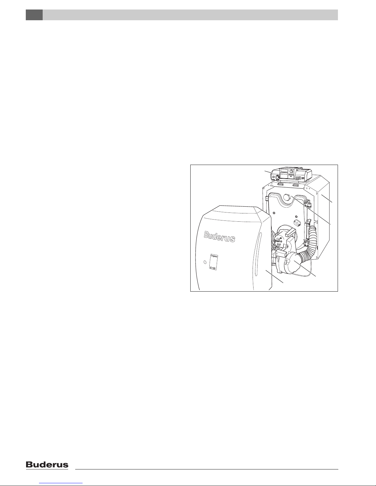
Fig. 1 Boiler G125 BE US/CA
1 Control panel
2 Boiler jacket
3 Boiler block with insulation
4 Burner door cover
5 Burner
2
3
5
4
7 747 010 678-01.1RS
6
Logano G125 BE - Specification subject to change without notice.
3 Technical Information
3.1 Technical Data less Burner
25 1/2"
23 1/2"
14 1/2"
Technical Information
12 1/4"
3
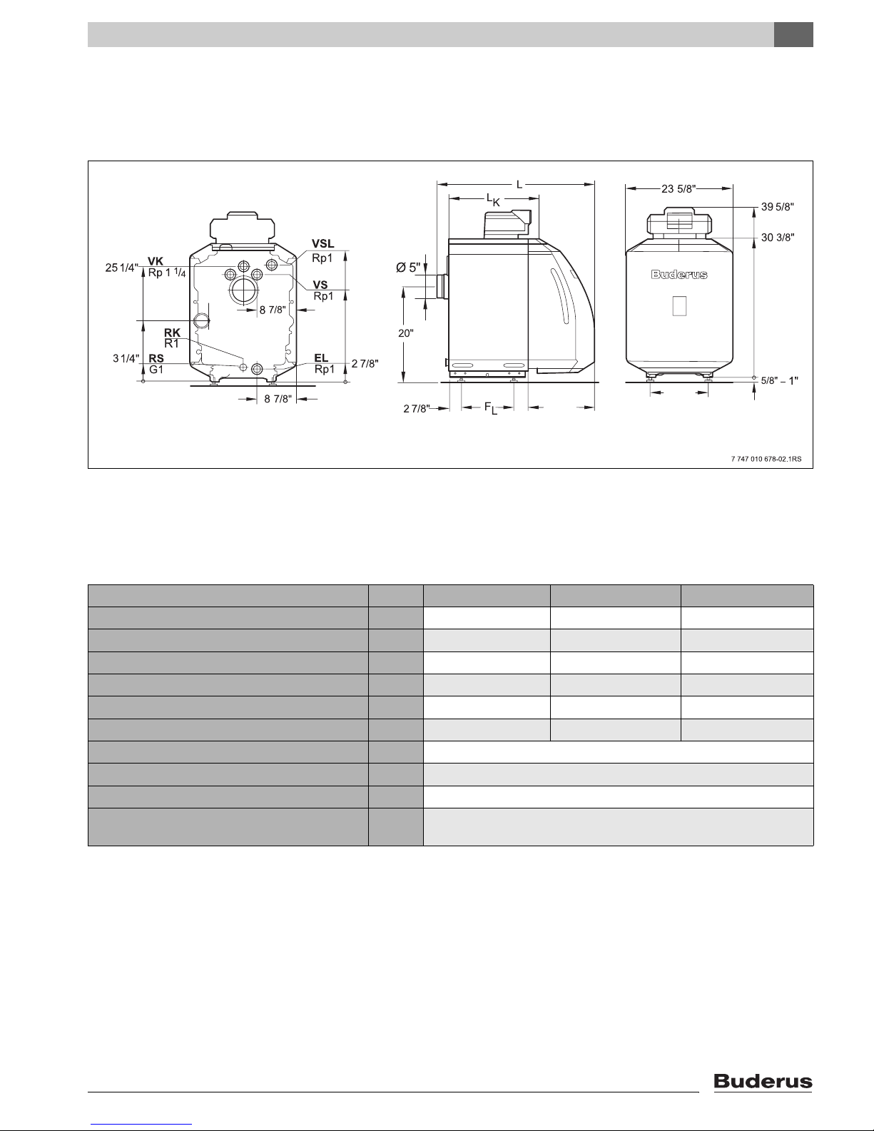
Fig. 2 Dimensions and connections (measurements in inches)
Connections (For Measurements see following tables):
VK = Boiler supply VS = Connection (plugged)
RK = Boiler return RS = Connection (plugged)
EL = Boiler drain (Connection for drain valve) VSL = Connection (plugged)
Boiler Model G125/21-BE G125/28-BE G125/34-BE
Number of boiler blocks 34 5
Heating Capacity (Gross Output) MBtu/hr 72 96 116
Net IBR MBtu/hr 63 83 101
Boiler water content Gal 8.7 10.8 12.9
Fireside volume cu.ft. 1.20 1.75 2.21
Oil firing rate GPH .60 .80 1.0
Fireside pressure drop psi 0.00058 – 0.00145
Permissible max. supply temperature
1
°F 230
Allowable operating pressure psi 58
Maximum Reset High Limit for temperature
s 40
sensor and overheat thermostat (STB)
Table 1 Technical Data for G125 BE less burner
1
High limit (overheat thermostat STB)
Permissible maximum supply temperature = High limit (STB) – 32 °F
e.g.: High limit (STB) = 212 °F, maximum permissible supply temperature = 212 – 32 = 180 °F
Select your high limit (STB setting) according to your local codes and requirements.
Logano G125 BE - Specifications subject to change without notice.
7

3
Technical Information
Boiler Model G125/21-BE G125/28-BE G125/34-BE
Total boiler length (L) 34 5/8” 39 3/8” 44”
Boiler block length (LK) 21 1/8” 25 3/4” 30 1/2”
Combustion chanber length 16” 20 1/2” 25 1/4”
Firebox diameter 10 5/8”
Burner door thickness 3 1/2”
Distance between boiler feet (FL) 11 3/8” 16 1/8” 20 7/8”
Dry weight
Table 2 Dimensions, Weight and other Data for G125 BE less burner
1
Weight incl. packaging material approx 6 – 8% more.
1
386lbs 459lbs 513lbs
3.2 Operating Conditions
Maintain the operating requirements listed on the following page for long and trouble free operation of the boiler.
Proper and timely maintenance procedures must be followed.
SYSTEM DAMAGE
CAUTION!
If these operating requirements are not
followed, it can lead to premature failure
can result and cause permanent damage
to the boiler.
z Follow the instructions on the rating la-
bel and those in the manual.
8
Logano G125 BE - Specifications subject to change without notice.
Technical Information
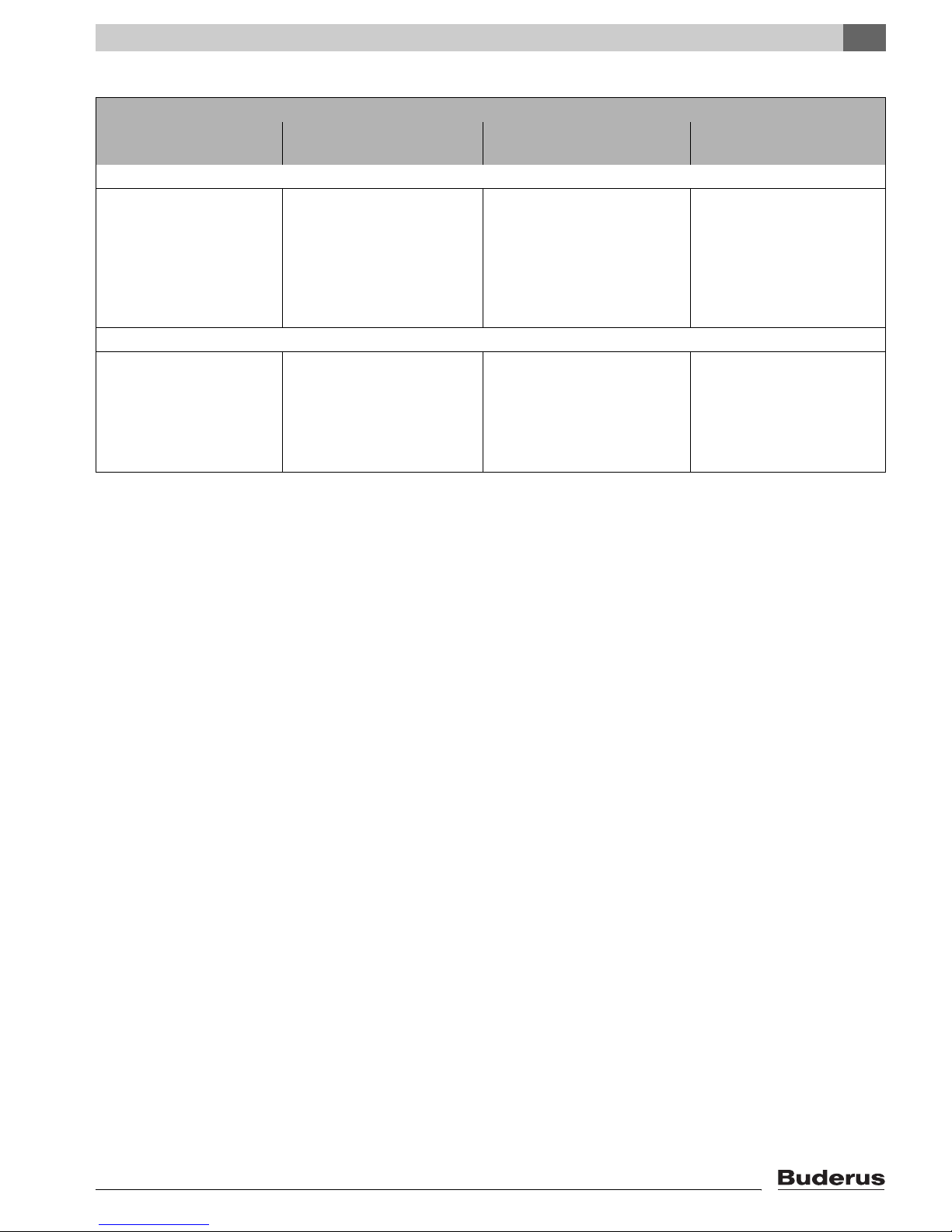
3.2.1 General Operating Requirements
Operating Conditions
Minimum Boiler tempera-
ture
Systems controlled by R2107 controls for outdoor reset operation
No requirements
Operating conditions are met
with R2107 control
150 °F
2
3
Table 3 General Operating Requirements
1
A heating circuit equipped with a motorized mixing valve improves the controllability of that sub-system and is specifically recommended when
requiring different water temperatures.
2
In case the control system has no influence over the flow in a heating circuit (for instance using the Pumplogic feature of the R2107), then one
should achieve a minimum supply temperature of 122 °F within 10 minutes after burner start-up by means of reducing (or interrupting) the water
flow through the boiler.
3
Minimum setting on the adjustable high limit or Aquasmart: During burner operation one should achieve the minimum boiler temperature within
10 minutes after burner start-up by means of flow reduction and one should maintain this temperature.
Boiler Shutdown Boiler Shutdown/
Mixed temperature
Automatic with Logamatic
R2107
No requirement, yet beneficial
with low temperature boiler with
130/113 °F system design
Necessary with:
– Radiant floor applications
– Systems with large water con-
tent > 115 gal/100,000 Btu/hr
Systems controlled by Aquasmart or R2109
Possible, provided the boiler op-
erates after total shut-down for
at least 3 hours.
1
Minimum return temperature
No requirement
Necessary Necessary for:
– Systems with large water
content > 115 gal/100,000
Btu/hr: 130 °F
– Firing with modulating burn-
ers: 130 °F
3
Logano G125 BE - Specifications subject to change without notice.
9
3
Technical Information
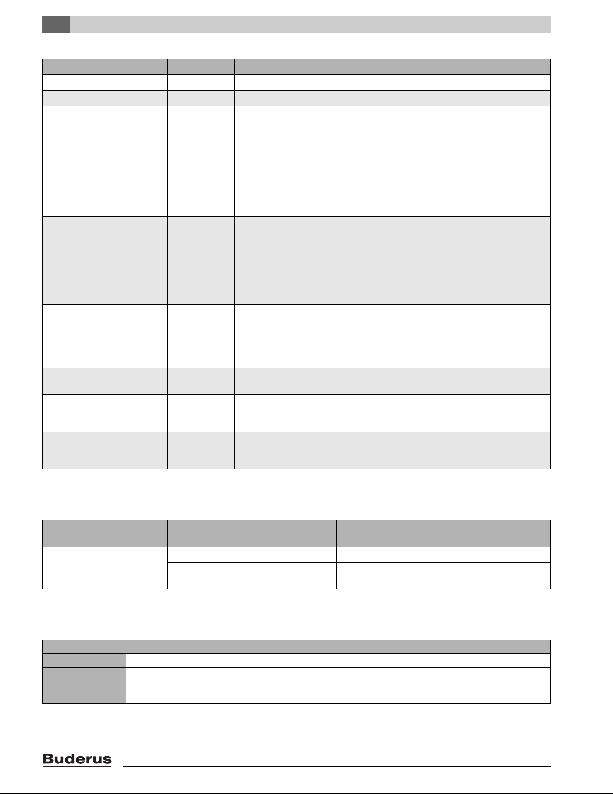
3.2.2 Requirements for Boiler Room and Surroundings
Operating Conditions Comments – Detailed Information
Boiler room temperature +40 to +104 °F
Relative humidity max. 90 % No condensate or dampness in boiler room.
Dust – No excess amounts of dust should be present in the boiler room, e.g.:
– No sheet rock or construction dust.
The available combustion air can not contain dust or other particles/ use of an air
filter might be needed, e.g.:
– Combustion air from nearby roads with high dust levels.
– Combustion air from nearby production facilities such as chemical plants &
shops.
– Airborne particulates.
Halogenated Hydrocarbons
contamination
Fans, removing air from boiler
room
Animals – The boiler room and especially the air inlet openings for combustion air must be
Fire Protection – Maintain proper clearances to combustible materials as required per local code.
Flood Zone Conditions – Separate the fuel supply and electrical power supply from the boiler during flood
– Combustion air must be free of halogenated hydrocarbons components.
– Eliminate any chemical compound such as paints, lacquers, thinners, clean-
ing agents. If not possible, provide fresh outside air for combustion.
Please observe the following:
– Product information of Buderus catalog.
– Also observe guidelines in K3 chapter of Buderus catalog.
– Avoid forced air removal by mechanical means during boiler operation such as:
– Bathroom exhaust fans
– Dryer
– Air-conditioning equipment
kept free from animals entering by means of grills.
Maintain a minimum distance of 16”. Do not store flammable materials near the
boiler.
conditions. Replace the boiler components such as insulation, electrical and control components afterwards.
Table 4 Boiler room and surroundings
3.2.3 Combustion Air Requirements
Operating Conditions Boiler capacity (combine total boiler ca-
pacity for multiple units)
Two air inlet openings from outside: one top, one near bottom
Table 5 Observe local codes and regulations for combustion air requirements
< 170,000 Btu/hr At least 43 square inch
> 170,000 Btu/hr At least 43 square inch plus 2.5 square inch per 10,000
Btu/hr, if the output is higher than 170,000 Btu/hr.
3.2.4 Fuel Conditions
Country All Countries
Fuel #2 Fuel Oil ASTM D396-05 Type 2
Comments No other fuel may be used with this burner.
Burner requires annual service and cleaning. Verify each time that the complete heating system is in working
order. Defects must be remedied immediately.
Table 6 Permitted fuel types
Cross area required
10
Logano G125 BE - Specifications subject to change without notice.
Technical Information
3
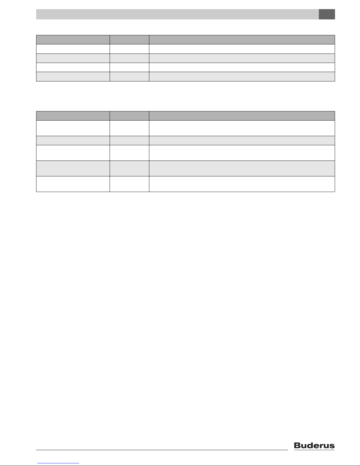
3.2.5 Requirements for Power Supply
Operating Conditions Comments – Detailed Information
Main power supply 120 V Provide proper grounding for equipment and personal protection.
High amp protection 10 A
Frequency 60 Hz
Protection – Group all equipment per local code
Table 7 Power supply
3.2.6 Conditions Pertaining to Piping and Water Quality
Operating Conditions Comments – Detailed Information
Operating pressure (over pressure)
Allowable test pressure 45 – 75 psi
Adjustable temperature limit TR122 – 194 °F
Manual reset high limit 210 °F In combination with Beckett AquaSmart the limit value (210 °F) may not be excee-
Water quality – Initial fill water and make-up water should be potable water type quality. A pH
12 – 58 psi Maximum pressure is 30 psi based on supplied relief valve
ded.
range of 8.2 to 9.5 is desired.
Table 8 Piping and water quality
Logano G125 BE - Specifications subject to change without notice.
11
4
Packaging and Components
4 Packaging and Components
z Check the packaging for concealed damage.
z Check the packaging for completeness. Contact your
wholesaler in case of missing parts.
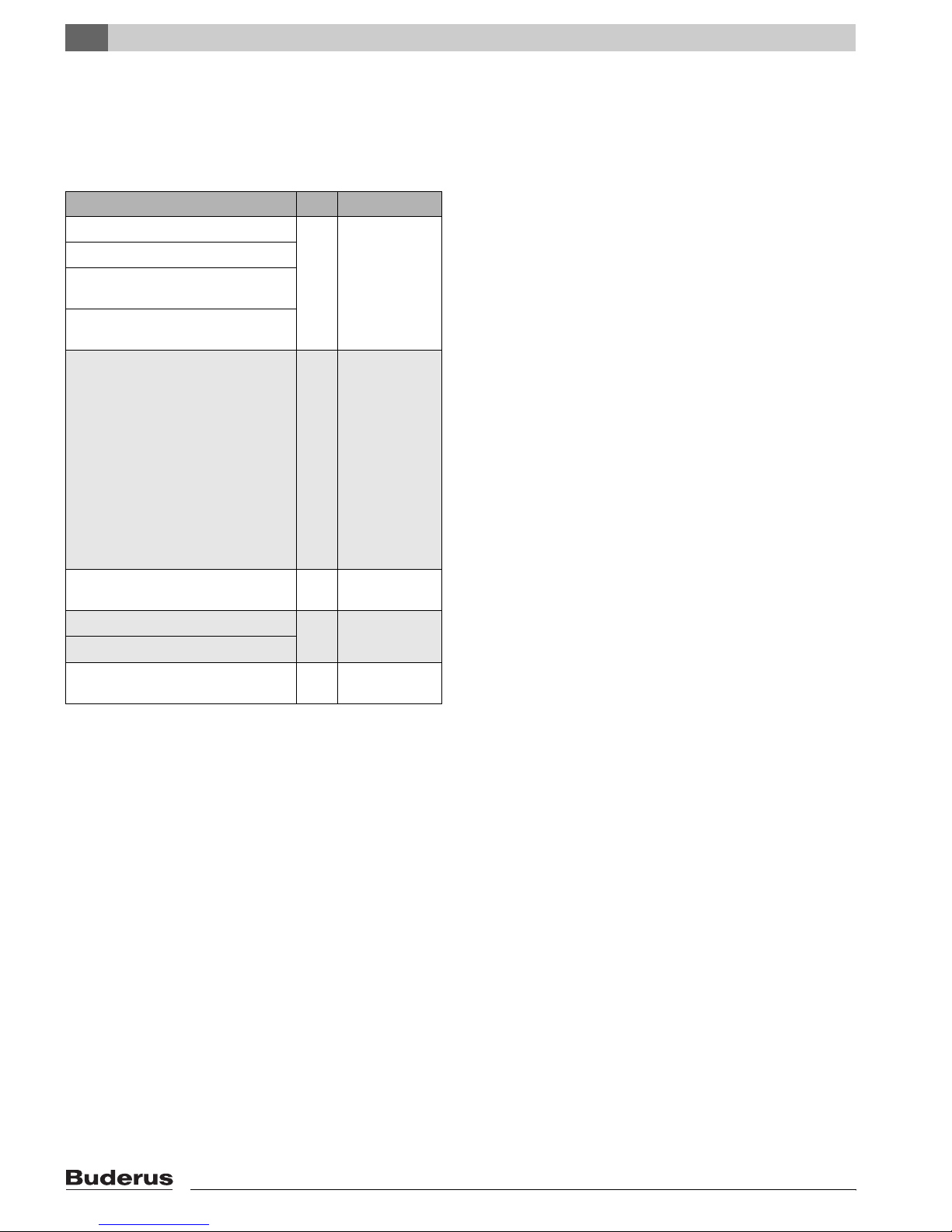
Component Qty Packaging
Boiler block 1 Pallet
Boiler jacket, installed on boiler
Burner door and burner door cover
installed on boiler block
Buderus oil burner mounted on customized burner door
B-Kit-Components:
Supply manifold (1¼" NPT)
30 psi relief valve
(¾") boiler drain
Pressure/temperature gauge
(1¼" NPT × R1¼) conversion nipple
(parallel to NPT)
90°-elbow (1¼" NPT)
90°-elbow (¾" NPT)
Burner mounting studs and washers
Screw in feet
14Plastic pack-
aging with boiler
Control panel, alternative Aquasmart control (ordered separately)
Tigerloop oil filter 1 included with
Taco 007 circulator pump w/flanges
Technical documents 1 Plastic pack-
Table 9 Packaging and components
Cardboard
box
boiler package
aging w/boiler
12
Logano G125 BE - Specifications subject to change without notice.
5 Moving the Boiler
This chapter describes how to move the boiler.
SYSTEM DAMAGE
due to bumps.
CAUTION!
z Protect the boiler from bumps and
rough treatment.
NOTICE
z Protect the boiler from connections
from damage and dirt, when the boiler
is not installed immediately.
NOTICE
Please dispose of the packaging in an environmentally friendly fashion.
Moving the Boiler
5
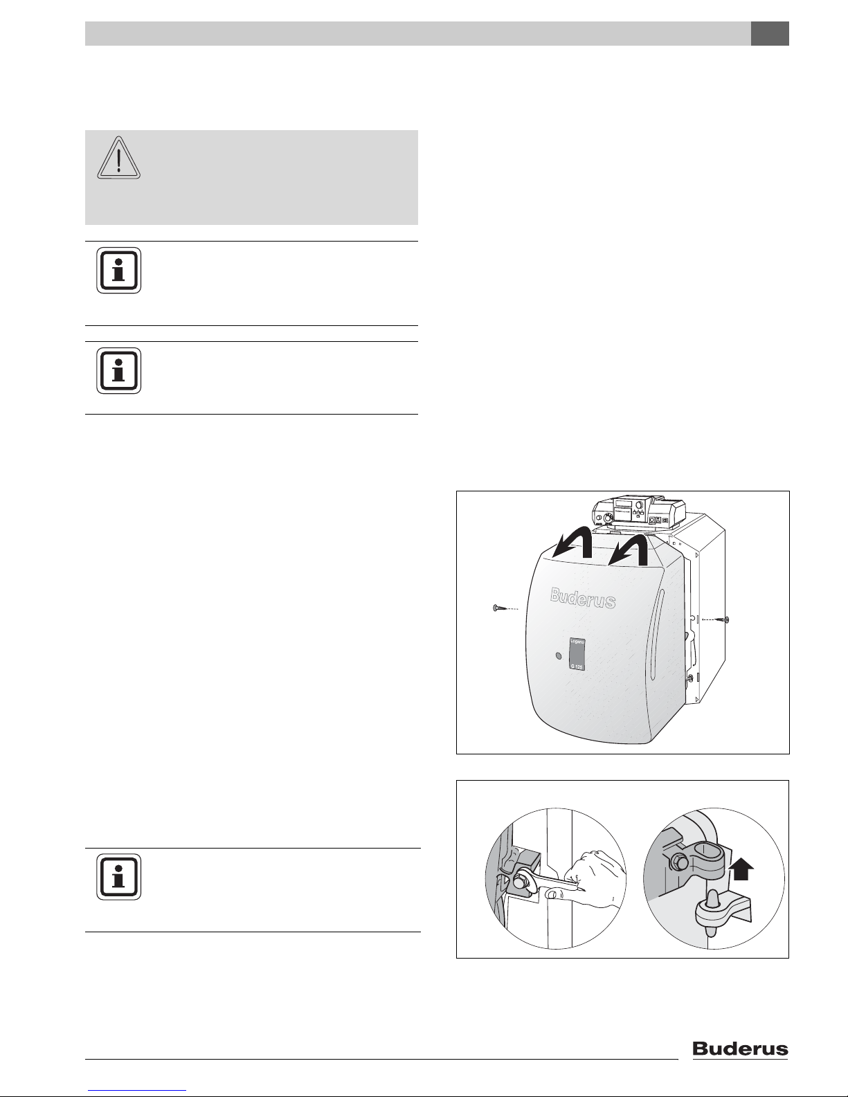
5.1 Reducing Boiler Weight for Transportation
One can reduce boiler weight by removing the front cover and burner door itself.
z Remove the screws holding the front cover in place.
z Lift up the front cover slightly and remove.
z Disconnect burner cable from burner control before
removing the burner door.
z Open burner door by removing the two burner door
bolts.
z Lift burner door from hinges.
NOTICE
Fig. 3 Removing the front cover
z Protect the burner door and the burner
tube from damage and dirt when the
burner door is removed from the boiler.
Logano G125 BE - Specifications subject to change without notice.
Fig. 4 Removal of burner door
13
5
Moving the Boiler
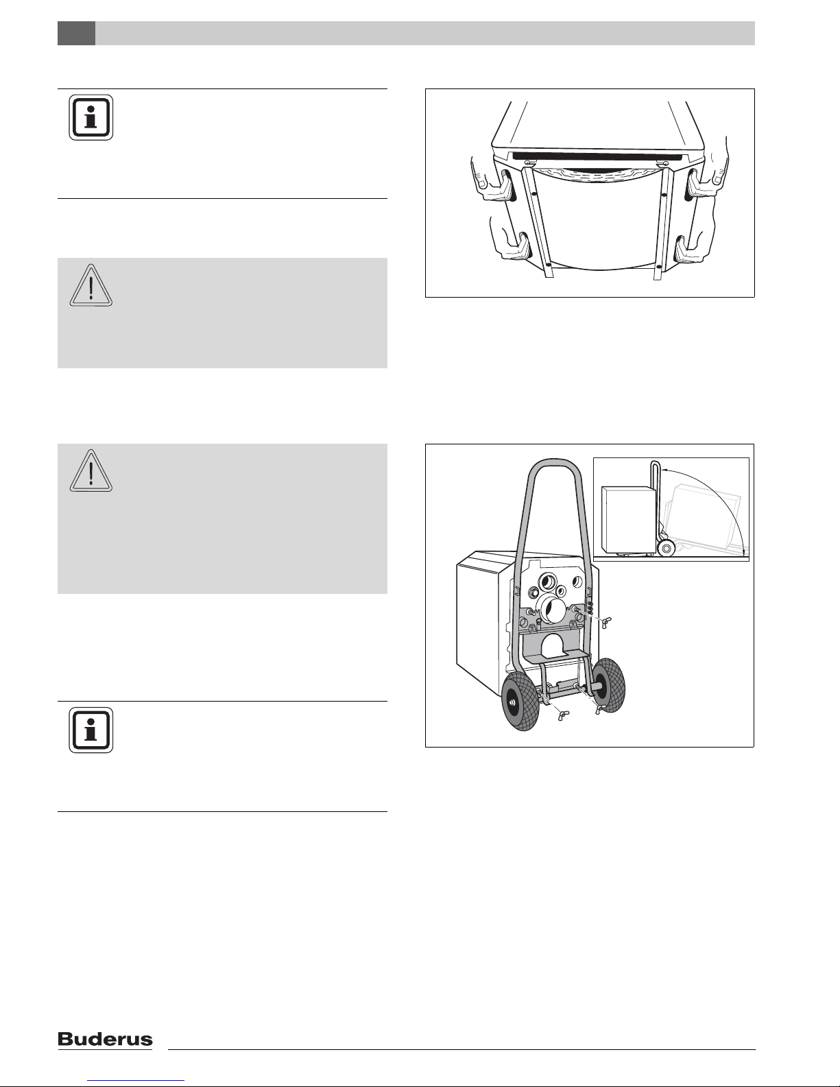
5.2 Lifting and Carrying the Boiler
NOTICE
The boiler is secured to the pallet with two
bolts.
z Remove the bolts from pallet before
lifting the boiler.
The boiler can be picked up at the hand grips located
along the lower jacket panels.
BODILY DANGER
due to carrying of heavy loads.
CAUTION!
z Lift and carry the boiler with at least
two people at the designated hand
grip positions.
5.3 Moving the Boiler with the Boiler Cart
BODILY DANGER
if the product is not properly secured to
CAUTION!
z Lift up the boiler from the rear side by using moving
equipment (e.g. Buderus card or other dolly).
z Secure the boiler to the cart.
z Move the boiler to the job location.
the cart.
z Use proper moving equipment such as
the Buderus cart or other dolly.
z Secure the boiler to the cart and move
the boiler to the job location.
Fig. 5 Lifting and carrying the boiler
NOTICE
By tipping the cart you can install the boiler feet (Î Chapter 6.3, page 17).
You can order a Buderus cart from your
local wholesaler.
14
Fig. 6 Moving the boiler with a Buderus cart
Logano G125 BE - Specifications subject to change without notice.
6 Placing the Boiler
This chapter discusses how to place the boiler in the
boiler room.
SYSTEM DAMAGE
due to freezing temperatures
CAUTION!
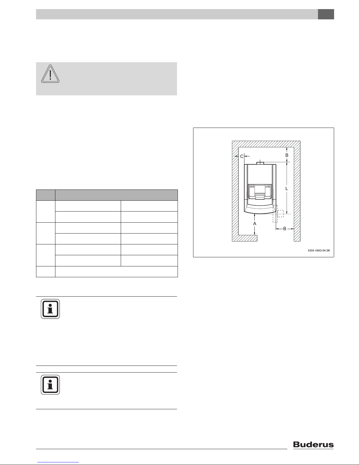
6.1 Clearances
Position the boiler while observing the clearances in
(Î Fig. 7). Access to the boiler is reduced when reducing these clearances.
The boiler foundation must be level and sufficiently
strong.
The burner door is factory installed right swinging. Youcan reverse the door swing in the field.
z Place the boiler in a frost free room.
Placing the Boiler
6
Distance
A Recommended 51 1/8"
minimum 39 3/8"
B Recommended 27 1/2"
minimum 15 3/4"
C Recommended 15 3/4"
minimum 3 7/8"
L see Chapter 3 „Technical Information“
Table 10 Recommended and minimum clearances
(Measurement in Inches)
NOTICE
Smaller clearances must abide with state
and local code. The boiler is approved for
6" side clearances. A minimum distance
of 18" to combustible materials must be
maintained per NFPA 31.
Floor material must comply with
NFPA 31.
Fig. 7 Clearance dimensions for G125 boilers
NOTICE
Observe required distances to other components such as water piping, venting
and other components.
Logano G125 BE - Specifications subject to change without notice.
15
6
Placing the Boiler
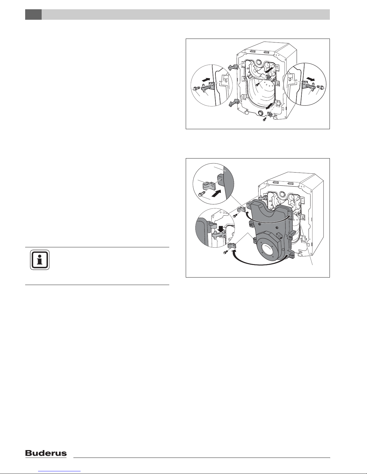
6.2 Reversing the Burner Door Swing
The burner door hinges are factory installed on the right
handside the burner door swings to the right. You can
adjust the hinges so that the burner door swings to the
left in the field.
Note: the front panel must first be removed.
(Î Chapter 5.1, page 13).
z Remove burner door (Î Chapter 5.1, page 13).
z Remove hex head bolts of burner door hinges and re-
move hinges.
z Install the hinges on the left side of the boiler with the
hex head bolts.
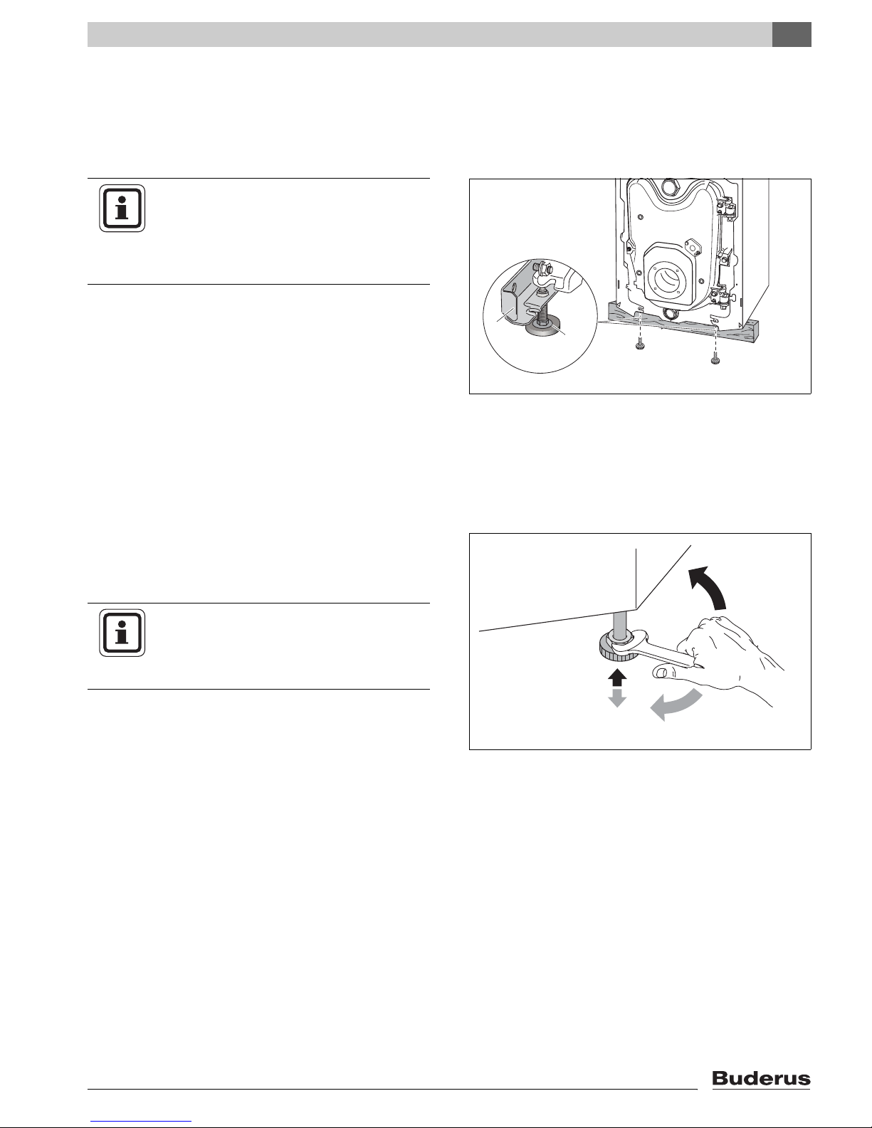
z Remove the eyelets from the burner door by remov-
ing the hex head bolts.
z Locate and secure with hex head bolts these eyelets
to the left side of the burner door.
z Hang the burner door on the hinges.
z Check to make sure that the flue baffle plates are
horizontally in the boiler (Î Chapter 8.3, page 40).
z Secure the burner door with the burner door bolts.
Make sure to tighten the burner door bolts evenly
with about 7.5 ft-lbs torque.
NOTICE
When reversing the swing of the burner
door, make sure to remove the burner cable and oil line from the burner first.
2
1
Fig. 8 Reversing burner door (boiler block)
1 Hex head bolts for hinges
2 Door hinges
3
2
1
4
Fig. 9 Reversing burner door (on burner door)
1 Hex head bolts for door eyelets
2 Door eyelet
3 Burner door
4 Door hinges
5 Flue baffles
1
2
5
16
Logano G125 BE - Specifications subject to change without notice.
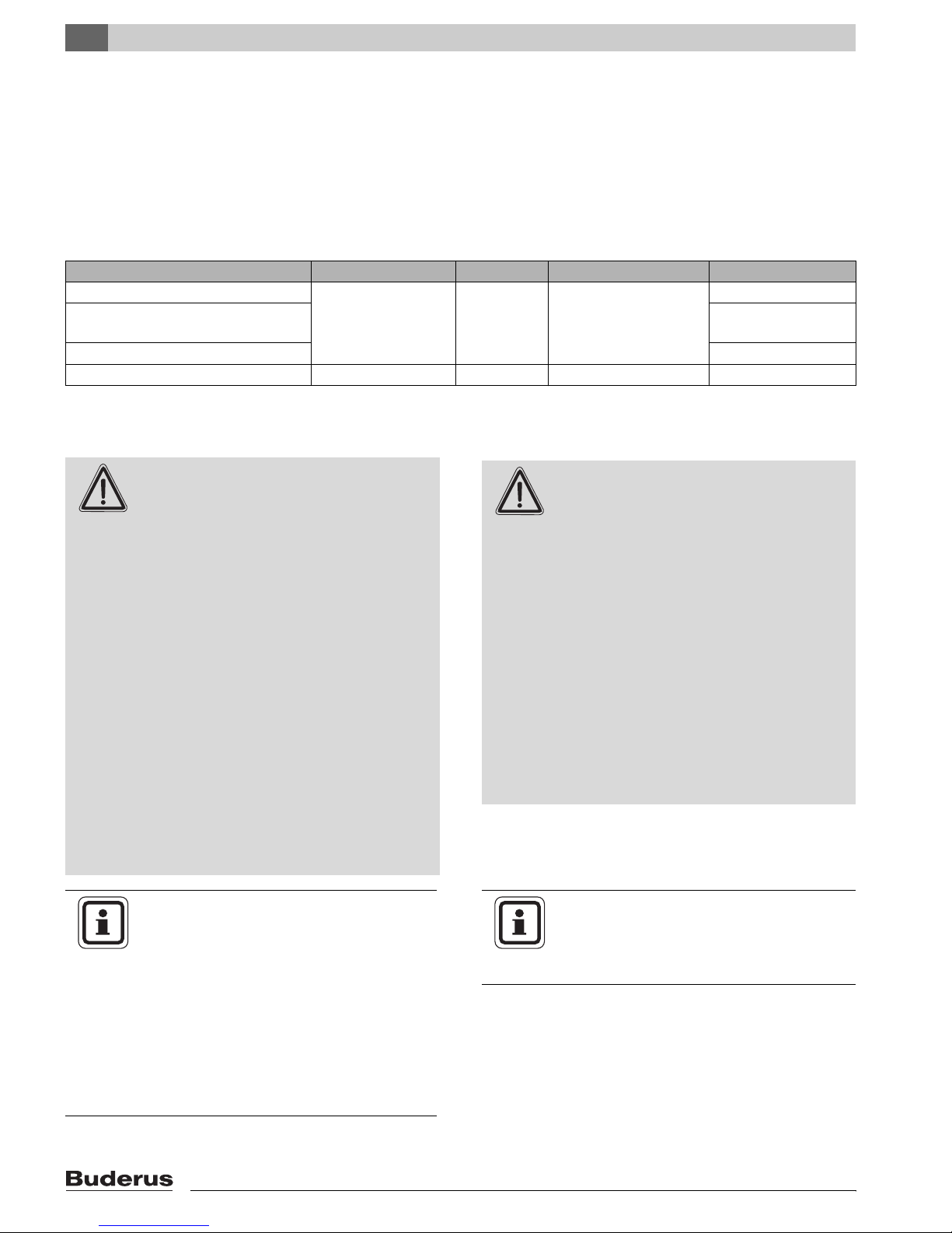
6.3 Installation of boiler Feet (Components of B-Kit)
You can level the boiler using the screw-in boiler feet, so
that air can not collect in the boiler.
Requirement: remove front panel from boiler
(Î Chapter 5.1, page 13).
NOTICE
When installing a G125 BE boiler on top
of a horizontal Buderus DHW indirect
tank, do not use the boiler feet on the boiler, but rather use the feet to level the tank.
z Tip the boiler slightly using the boiler cart
(Î Chapter 5.3, page 14) or put a piece of wood under one side.
z Screw in the boiler feet 1/4" – 3/8".
1
Placing the Boiler
6
2
z Level the boiler.
6.4 Placement of the Boiler
z Bring the boiler to its final location.
z Put a level on the boiler and adjust boiler feet to level
the boiler.
NOTICE
z Protect the boiler connections from
dust and debris, if the boiler will not be
connected right away.
Fig. 10 Installation of boiler feet
1 Boiler rail
2 Boiler feet
Fig. 11 Leveling the boiler
Logano G125 BE - Specifications subject to change without notice.
17
7
Boiler Installation
7 Boiler Installation
7.1 Installation of Venting Systems
This chapter describes the installation of the venting
system and the combustion air supply system for the
G125 BE boiler.
Following venting options are available:
Venting system Comment Draft Combustion air Chapter
Masonry chimney (no liner) Barometric
Masonry chimney
w/ 5" liner
Vertical vent 5" 7.1.1.3, Page 21
Side wall Sealed vent Positive Outside air only 7.1.2, Page 22
Table. 11Venting options
damper
required
Negative Outside air or room air 7.1.1.1, Page 19
7.1.1.2, Page 20
WARNING!
DANGER TO LIFE
from toxic flue gases.
z Never connect more than one appli-
ance to a venting system - regardless of
vertical or horizontal venting.
z Common venting of appliances can
cause property damage and put life at
risk.
z Chimney liners must be a single contin-
uous piece inside an existing chimney
and can not have any connections inside the chimney chase.
z The venting system shall not be routed
into, through, or within any other vent,
such as an existing masonry or factorybuilt chimney that is used to vent any
other appliance.
z Always follow vent manufacturer’s in-
structions.
NOTICE
WARNING!
FIRE DANGER
from insufficient clearance between vent
system components and combustible surfaces.
z Maintain 18" clearance to combustible
surfaces when using galvanized or
stainless pipe in vertical or horizontal
venting.
z Maintain 1" clearance to combustible
surfaces when using flexible oil vent for
horizontal venting.
z Both the Aerocowl (AT-4) exhaust ter-
mination and Fields (FT-4) concentric
exhaust/intake terminations are approved with zero clearance to combustible surfaces.
NOTICE
The boiler installation must be performed
by a qualified installer in accordance with
regulations put forth in NFPA-31 Installation of Oil-Burning Equipment. The installation must comply with all local and
national codes, regulations and authorities
having jurisdiction regarding the installation of oil fired boilers.
For Canada refer to the guidelines of
CSA/B139 Installation Codes.
18
z Avoid excessively long venting sys-
tems and keep the number of elbows to
a minimum.
Logano G125 BE - Specifications subject to change without notice.
NOTICE
Due to tight construction of modern
homes, Buderus recommends drawing
combustion air from outdoors. The boiler is
factory prepared for connecting 4" rigid
pipe ducted directly to the increaser at the
rear of the boiler. For further directions
Î Chapter 7.2, page 28.
Except for direct venting, and provided
ample combustion air is available in the
boiler room, combustion air can also be
drawn from the room (Î Chapter 7.2,
page 28 for details).
NOTICE
For Canada the G125 BE is approved
without a Blocked Vent Switch.
Should local authorities require a Blocked
Vent Switch Î Chapter Fig. 63, page 68.
Boiler Installation
7
7.1.1 Vertical Venting Systems
The G125 BE boiler can be vented vertically using an
existing masonry chimney or a factory built All-Fuel or Lvent chimney.
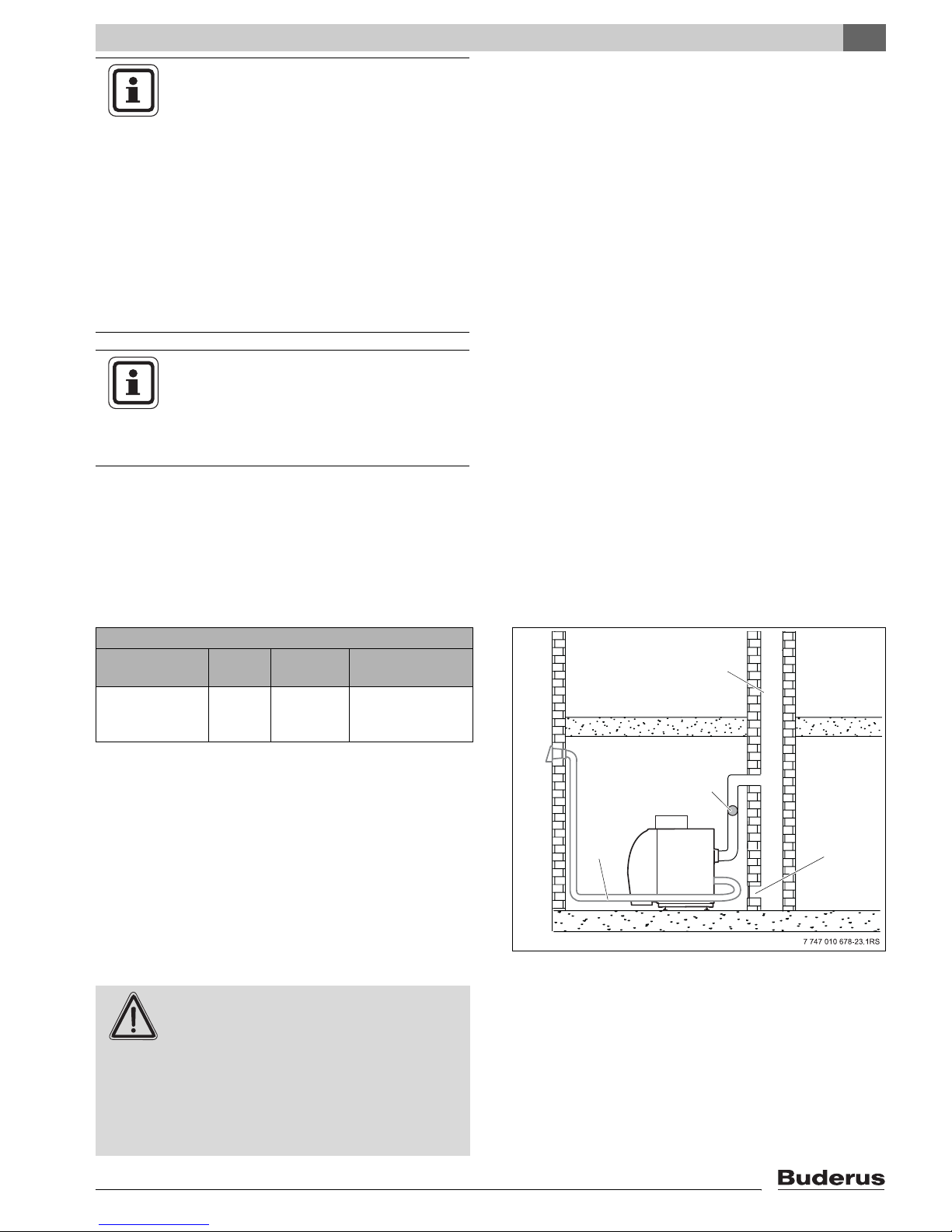
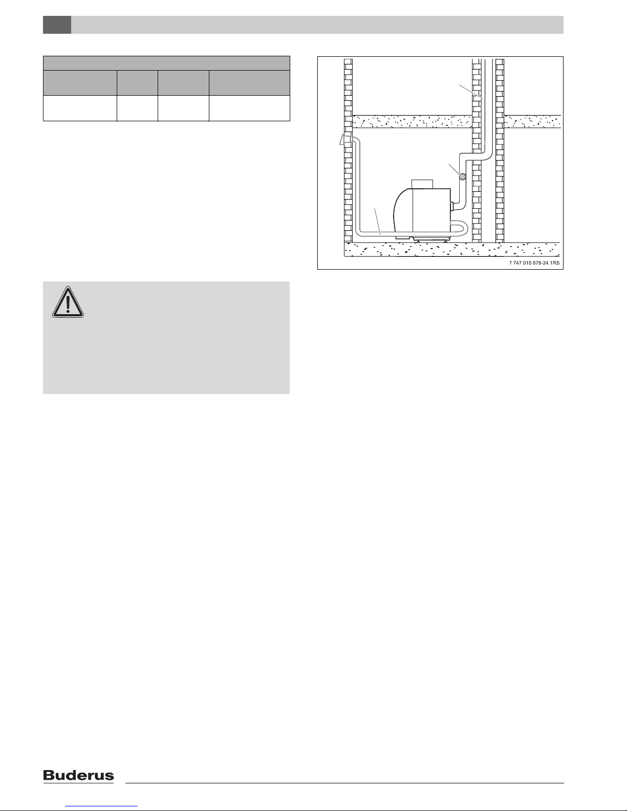
7.1.1.1 Masonry Chimney
Venting system: Masonry Chimney
Comment Draft Combus-
tion air
Barometric
damper
required
Negative Outside air
or room air
Max. vent length
60 ft.
Refer to NFPA 31 for requirements on chimney venting.
Old, cold or over-sized chimneys require the use of an
approved 5" chimney liner (Î Page 20).
The maximum vent length of a masonry chimney is 60 ft.
A masonry chimney is operated under slight negative
pressure, and requires a barometric damper.
z Follow damper manufacturer’s instructions as to
placement.
z Adjust draft for negative 0.02 – 0.04" W.C.
DANGER TO LIFE
from toxic flue gases.
WARNING!
z Verify that all vent pipe connections
have been installed properly.
1
2
4
Fig. 12 Masonry chimney installation
1 Chimney
2 Barometric damper
3 Clean-out
4 Horizontal air connection for combustion air
(optional, see 7.2)
3
z Have the entire venting system cleaned
and inspected annually by a qualified
service company.
Logano G125 BE - Specifications subject to change without notice.
19
7
Boiler Installation
7.1.1.2 Chimney with 5" Liner
Venting system: Chimney with 5" Liner
Comment Draft Combus-
tion air
Barometric
damper required
Negative Outside air
or room air
Max. Vent length
60 ft.
Install liner according to manufacturer’s instructions.
Follow all applicable local and national codes and regulations.
The maximum vent length of 5" liner in a masonry chimney is 60 ft.
The 5" liner in a chimney is operated under slight negative pressure, which requires a barometric damper.
z Follow damper manufacturer’s instructions as to
placement.
1
2
3
z Adjust draft for negative 0.02 – 0.04" W.C.
DANGER TO LIFE
from toxic flue gases.
WARNING!
z Verify that all vent pipe connections
have been installed properly.
z Have the entire venting system cleaned
and inspected annually by a qualified
service company.
Fig. 13 5" Chimney liner installation
1 5" Chimney liner
2 Barometric damper
3 Horizontal air connection for combustion air
(optional, see 7.2)
20
Logano G125 BE - Specifications subject to change without notice.
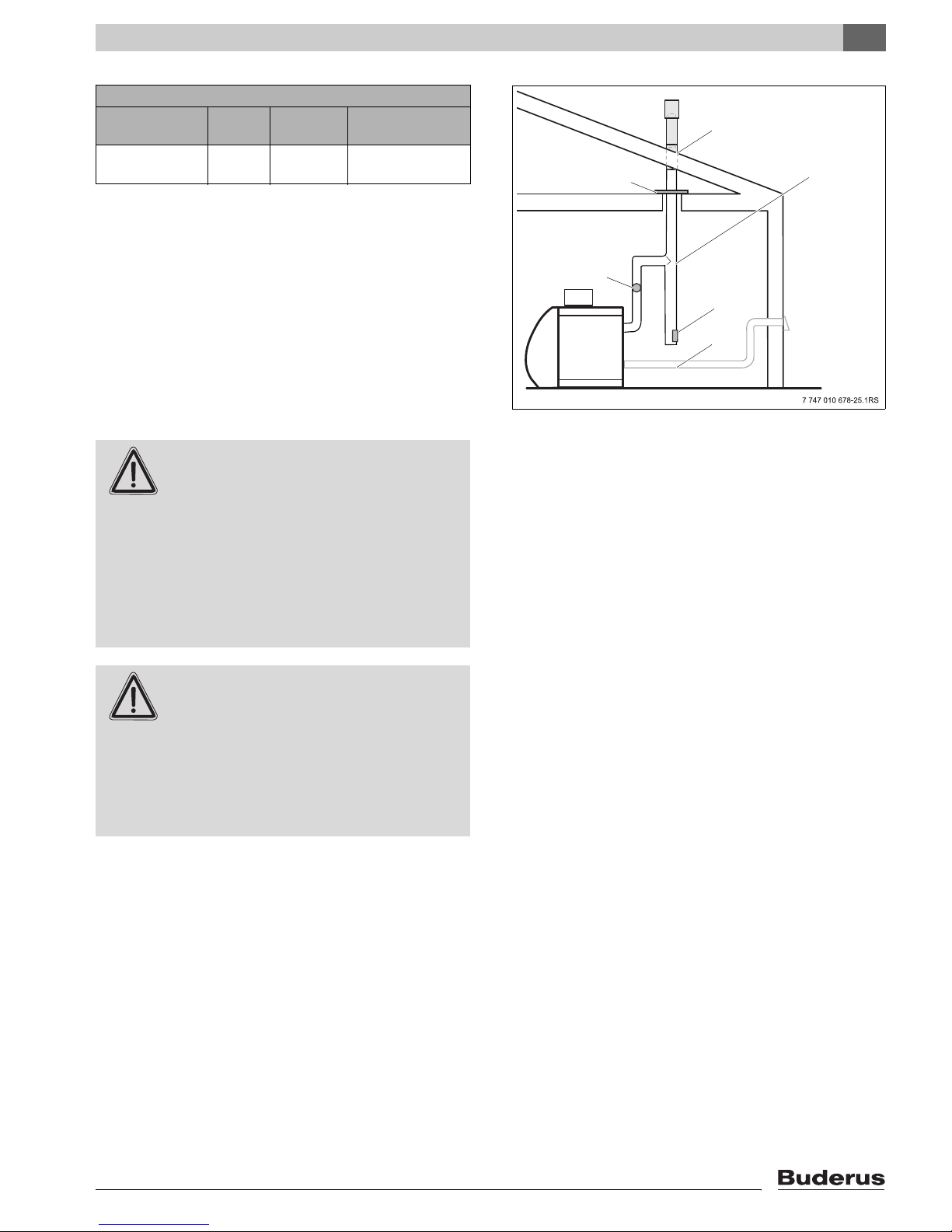
7.1.1.3 Vertical Vent
Venting system: 5" Vertical Vent
Comment Draft Combus-
tion air
Barometric
damper required
Negative Outside air
or room air
Max. Vent length
60 ft.
Extend the vertical vent pipe sufficiently far above the
roof per NFPA 31. Follow all applicable local and national codes and regulations.
Boiler Installation
7
1
2
3
The maximum length of the vertical 5" venting system is
60 ft.
The 5" vertical venting system operates under a slight
negative pressure, which requires a barometric damper.
z Follow damper manufacturer’s instructions as to
placement.
z Adjust draft for negative 0.02 – 0.04" W.C.
DANGER TO LIFE
from toxic flue gases.
WARNING!
z Vertical vent pipe must have an ap-
proved fire stop at each ceiling penetration and the stack must be properly
supported at its base.
z Each venting section must be support-
ed at each elbow and at least every 48"
of straight pipe.
DANGER TO LIFE
from toxic flue gases.
WARNING!
z Verify that all vent pipe connections
have been installed properly.
4
5
6
Fig. 14 Vertical venting system installation (supports are not
shown for clarity)
1 Roof Penetration
2 Fire stop
3 All-Fuel or L vent flue pipe
4 Barometric Damper
5 Clean-out
6 Horizontal air connection for combustion air
(optional, see 7.2)
z Have the entire venting system cleaned
and inspected annually by a qualified
service company.
Logano G125 BE - Specifications subject to change without notice.
21
7
Boiler Installation
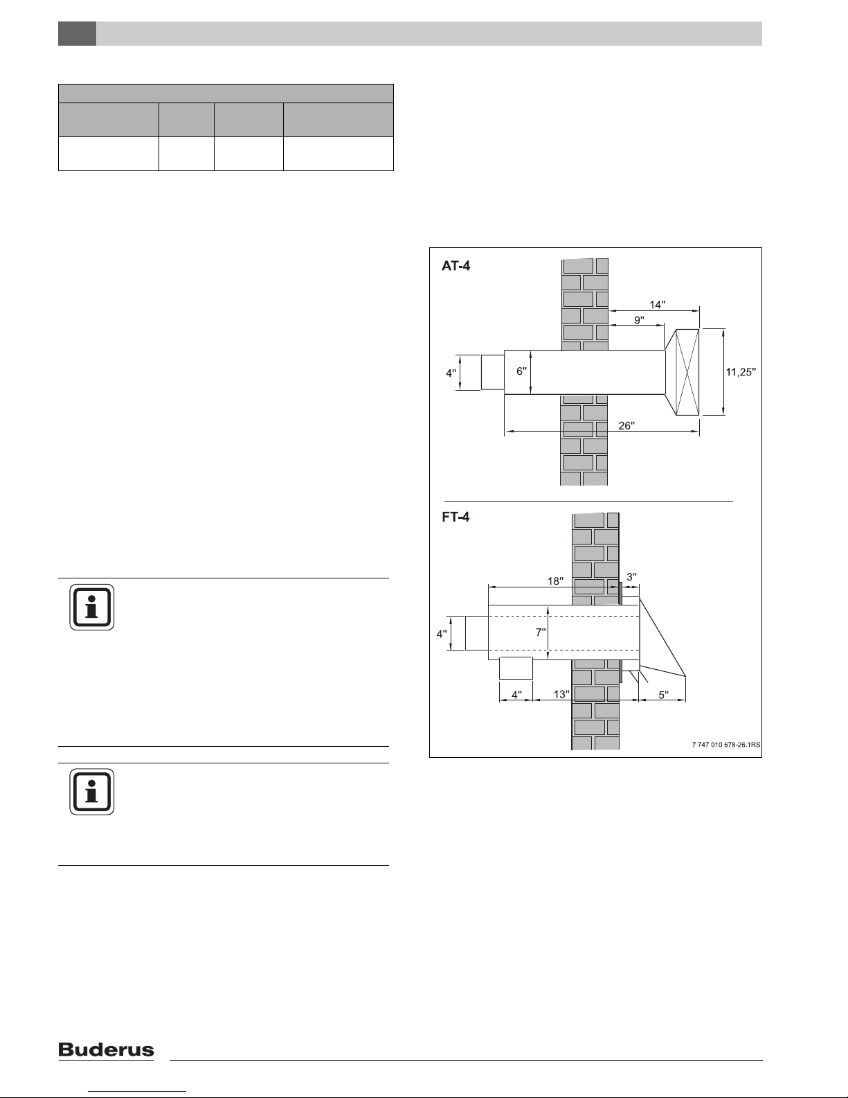
7.1.2 Horizontal Venting
Venting system: Side wall
Comment Draft Combus-
tion air
Sealed vent Positive Outside air
only
Max. Vent length
20 ft.
The maximum length of the direct vent system is 20 ft. of
linear pipe including 3 x 90° elbows. With 4 elbows the
maximum pipe length is 10 ft.
The following two direct vent terminations are approved
with the G125 BE, and are available for purchase from
your Buderus supplier.
Both exhaust terminations are approved for use with two
different exhaust vent pipe options.
– Option 1:
Flexible, insulated 4" stainless steel oil vent. The insulated oil vent is rated for 1" clearance to combustibles. Wrap the adapters with 3" of ceramic wool
covered with foil tape or sheet metal to maintain 1"
clearance. For installation instructions Î Chapter
„7.1.2.6 Installation of Insulated Flexible Oil Vent“,
page 26.
– Option 2:
Standard, 26 gauge galvanized 4" vent pipe. Maintain 18" clearance to combustibles with galvanized
vent pipe (Î Chapter „7.1.2.7 Installation of Galvanized Vent Pipe“, page 27).
NOTICE
Horizontal vent systems operate under
positive pressure, which requires all
seams to be sealed. Use high temperature
silicone (500°F rated, G.E. 106 or equivalent) to seal any joints, screw penetrations,
or combustion test holes, and seal at each
pipe connection and all joints on adjustable elbows. Refer to 7.1.2.2 for details.
NOTICE
Installations in Canada less than 7 ft.
above ground are required to have a
cage/screen over the termination to prevent injury from touching hot surfaces.
Fig. 15 Aerocowl (AT-4) and Concentric (FT-4) termination
22
Logano G125 BE - Specifications subject to change without notice.
 Loading...