

Buderus Logano G124X II/SP Installation And Maintenance Instructions Manual
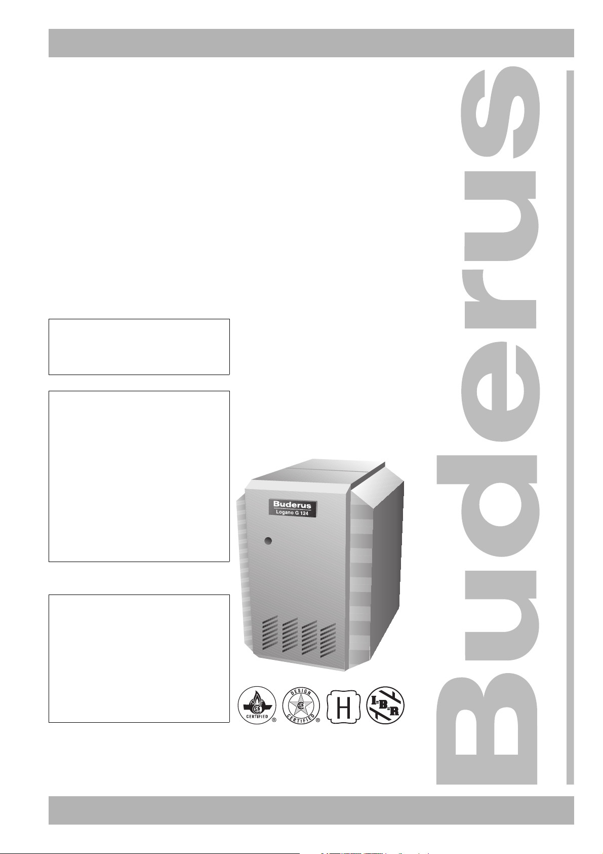
6304 0308 – 04/2005 US For heating engineers
Installation and maintenance
instructions
Gas boiler
Logano G124X II/SP
CAUTION!
Observe the safety instructions of this
installation and maintenance manual
before placing the boiler in operation.
WARNING!
If installation, adjustment, modification,
operation or maintenance of the
heating system is carried out by an
unqualified person, this may result in
danger to life and limb or property
damage. The directions of this
installation and maintenance manual
must be followed precisely. Contact a
qualified service company, service
provider or the gas company if support
or additional information is required.
CAUTION!
The operating manual is a component
of the technical documentation handed
over to the operator of the heating
system. Discuss the instruction in this
manual with the owner or operator of
the heating system to ensure that they
are familiar with all information required
for operation of the heating system.
Note: Keep this installation and maintenance manual available for future
reference.
Please read carefully prior to installation and maintenance.

Contents
1Safety. . . . . . . . . . . . . . . . . . . . . . . . . . . . . . . . . . . . . . . . . . . . . . . . . . . . . 4
1.1 Correct use . . . . . . . . . . . . . . . . . . . . . . . . . . . . . . . . . . . . . . . . . . . . . . . 4
1.2 Observe the following symbols . . . . . . . . . . . . . . . . . . . . . . . . . . . . . . . . . . . 4
1.3 Please observe these notes . . . . . . . . . . . . . . . . . . . . . . . . . . . . . . . . . . . . . . 4
1.4 Tools, materials and accessories . . . . . . . . . . . . . . . . . . . . . . . . . . . . . . . . . 6
1.5 Disposal . . . . . . . . . . . . . . . . . . . . . . . . . . . . . . . . . . . . . . . . . . . . . . . . . 6
2 Product description . . . . . . . . . . . . . . . . . . . . . . . . . . . . . . . . . . . . . . . . . . 7
3 Dimensions and connections . . . . . . . . . . . . . . . . . . . . . . . . . . . . . . . . . . 8
4 Scope of delivery . . . . . . . . . . . . . . . . . . . . . . . . . . . . . . . . . . . . . . . . . . . . 9
5 Moving the boiler . . . . . . . . . . . . . . . . . . . . . . . . . . . . . . . . . . . . . . . . . . . 10
5.1 Moving the boiler with boiler cart . . . . . . . . . . . . . . . . . . . . . . . . . . . . . . . . . 10
5.2 Lifting and carrying the boiler . . . . . . . . . . . . . . . . . . . . . . . . . . . . . . . . . . . 11
6 Placing the boiler. . . . . . . . . . . . . . . . . . . . . . . . . . . . . . . . . . . . . . . . . . . 12
6.1 Clearances . . . . . . . . . . . . . . . . . . . . . . . . . . . . . . . . . . . . . . . . . . . . . . 12
6.2 Leveling the boiler. . . . . . . . . . . . . . . . . . . . . . . . . . . . . . . . . . . . . . . . . . 12
7 Boiler installation. . . . . . . . . . . . . . . . . . . . . . . . . . . . . . . . . . . . . . . . . . . 13
7.1 Preparing for installation . . . . . . . . . . . . . . . . . . . . . . . . . . . . . . . . . . . . . . 13
7.2 Connecting the heating system. . . . . . . . . . . . . . . . . . . . . . . . . . . . . . . . . . 14
7.3 Electrical connection . . . . . . . . . . . . . . . . . . . . . . . . . . . . . . . . . . . . . . . . 16
7.4 Installation of Logamatic 2107 control (accessory). . . . . . . . . . . . . . . . . . . . . . 17
7.5 Fuel supply connection. . . . . . . . . . . . . . . . . . . . . . . . . . . . . . . . . . . . . . . 21
7.6 Filling heating system and checking for leaks . . . . . . . . . . . . . . . . . . . . . . . . . 23
8 Check openings for combustion air supply and venting . . . . . . . . . . . . . 24
9 Requirements for connection to chimneys or venting systems . . . . . . . 25
10 Flue pipe installation . . . . . . . . . . . . . . . . . . . . . . . . . . . . . . . . . . . . . . . . 26
11 Placing the heating system in operation . . . . . . . . . . . . . . . . . . . . . . . . . 28
11.1 Start-up instructions. . . . . . . . . . . . . . . . . . . . . . . . . . . . . . . . . . . . . . . . . 30
11.2 Making G124X II and G124X SP boilers ready for operation . . . . . . . . . . . . . . . 31
11.3 Conducting final commissioning for G124X II boiler . . . . . . . . . . . . . . . . . . . . . 32
11.4 Conducting final commissioning for G124X SP boiler . . . . . . . . . . . . . . . . . . . . 36
11.5 Shutting off gas supply to boiler . . . . . . . . . . . . . . . . . . . . . . . . . . . . . . . . . 40
11.6 Instruct owner/operator and hand over technical documentation . . . . . . . . . . . . . 41
11.7 Start-up protocol. . . . . . . . . . . . . . . . . . . . . . . . . . . . . . . . . . . . . . . . . . . 42
12 Taking the boiler out of operation . . . . . . . . . . . . . . . . . . . . . . . . . . . . . . 43
12.1 Normal boiler shut-down . . . . . . . . . . . . . . . . . . . . . . . . . . . . . . . . . . . . . . 43
12.2 Emergency shut-down . . . . . . . . . . . . . . . . . . . . . . . . . . . . . . . . . . . . . . . 43
We reserve the right to make any changes due to technical modifications.
2
Installation and maintenance instructions Logano G124X II/SP special gas-fired boiler • Issue 04/2005

Contents
13 Boiler inspection and maintenance. . . . . . . . . . . . . . . . . . . . . . . . . . . . . . 44
13.1 Why is regular maintenance important? . . . . . . . . . . . . . . . . . . . . . . . . . . . . . 44
13.2 Testing the flue system, including combustion air, air inlets and ventilation openings . 44
13.3 Inspection of the boiler and burner . . . . . . . . . . . . . . . . . . . . . . . . . . . . . . . . 44
13.4 Preparing boiler for cleaning . . . . . . . . . . . . . . . . . . . . . . . . . . . . . . . . . . . . 44
13.5 Cleaning the boiler . . . . . . . . . . . . . . . . . . . . . . . . . . . . . . . . . . . . . . . . . . 45
13.6 Cleaning the burner . . . . . . . . . . . . . . . . . . . . . . . . . . . . . . . . . . . . . . . . . 48
13.7 Troubleshooting on the G124X II . . . . . . . . . . . . . . . . . . . . . . . . . . . . . . . . . 49
13.8 Troubleshooting on the G124X SP . . . . . . . . . . . . . . . . . . . . . . . . . . . . . . . . 51
13.9 Maintenance protocol . . . . . . . . . . . . . . . . . . . . . . . . . . . . . . . . . . . . . . . . 53
14 Parts lists . . . . . . . . . . . . . . . . . . . . . . . . . . . . . . . . . . . . . . . . . . . . . . . . . 55
15 Specifications . . . . . . . . . . . . . . . . . . . . . . . . . . . . . . . . . . . . . . . . . . . . . . 73
16 Wiring diagrams . . . . . . . . . . . . . . . . . . . . . . . . . . . . . . . . . . . . . . . . . . . . 74
We reserve the right to make any changes due to technical modifications.
Installation and maintenance instructions Logano G124X II/SP special gas-fired boiler • Issue 04/2005
3
Safety1
1 Safety
Observe these instructions for your safety.
The burner and control must be correctly installed and
adjusted to ensure safe and economical operation of the
special gas-fired boiler.
Read this installation and maintenance manual carefully
and note the details on the boiler nameplate before
placing the boiler in operation.
1.1 Correct use
The Logano G124X II/SP special gas-fired boiler is
designed to heat water for a hot water heating system
for heating single or multiple occupancy buildings.
1.2 Observe the following symbols
Two levels of danger are identified and signified by the
following terms:
WARNING!
CAUTION!
Additional symbols for identification of dangers and user
instructions:.
RISK TO LIFE
Identifies possible dangers emanating
from a product, which might lead to serious
injury or death if appropriate care is not
taken.
RISK OF INJURY/
SYSTEM DAMAGE
Identifies potentially dangerous situations,
which might lead to medium or slight
injuries or to material losses.
RISK TO LIFE
from electric shock.
1.3 Please observe these notes
1.3.1 National regulations
The heating system must comply with the relevant
regulations issued by national authorities, or the
regulations issued by the National Fuel Gas Code, ANSI
Z 223.1. In Canada the regulations of CAN/CGA B 149.1
or 2, Installation Code for Gas Burning Appliances and
Equipment, must be observed.
If specified by the local regulatory authorities the heating
system must comply with the regulations of the
"Standard for Controls and Safety Devices for
Automatically Fired Boilers", ANSI/ASME CSD-1.
Carbon monoxide detoectors must be installed as
specified by the local regulations. The boiler must be
serviced annually
Boiler operating conditions
Maximum boiler temperature 220 °F
Maximum operating pressure 58 psi
The hot water pipe system must comply with the current
legislation and regulations. If an existing boiler is
replaced, the complete hot water pipe system must be
inspected to ensure that it is in perfect condition to
ensure safe operation.
WARNING!
(Î Chapter 13, page 44).
RISK TO LIFE
due to neglecting your own safety in case
of emergency, such as with a fire.
z Never put yourself at risk. Your own
safety must always take priority.
WARNING!
4
USER NOTE
Tip for the optimum utilization and setting
of the control(s) plus other useful
information.
We reserve the right to make any changes due to technical modifications.
Installation and maintenance instructions Logano G124X II/SP special gas-fired boiler • Issue 04/2005
Safety 1
WARNING!
CAUTION!
WARNING!
RISK TO LIFE
from explosion of flammable gases.
If you smell gas there is a danger of
explosion.
z Never work on gas lines unless you are
licensed for this type of work.
z Make sure that a qualified company
installs the boiler, connects gas and
venting, places the boiler in operation,
connects the electrical power, and
maintains and repairs the boiler.
z No open flame. No smoking. Do not
use lighters.
z Prevent spark formation.
Do not operate electrical switches,
including telephones, plugs or door
bells.
z Close main gas valve.
z Open doors and windows.
z Warn other occupants of the building,
but do not use door bells.
z Call gas company from outside the
building.
z If gas can be heard escaping, leave the
building immediately, prevent other
people from entering, notify police and
fire from outside the building.
SYSTEM DAMAGE
due to incorrect installation.
z Observe all current standards and
guidelines applicable to the installation
and operation of the heating system as
applicable in your country.
RISK TO LIFE
from electric shock.
z Disconnect the power supply to the
heating system before conducting any
work on it, e.g. switch off the heating
emergency switch outside the boiler
room.
z It is not sufficient just to switch off the
control.
SYSTEM DAMAGE
due to unsatisfactory cleaning and
CAUTION!
maintenance.
z Clean and service the system once a
year. Check that the complete heating
system operates correctly.
z Immediately correct all faults to prevent
system damage.
USER NOTE
Only use original Buderus spare parts.
Losses caused by the use of parts not
supplied by Buderus are excluded from the
Buderus warranty.
1.3.2 Installation notes
RISK TO LIFE
from explosion of flammable gases.
WARNING!
z Never work on gas lines unless you are
licensed for this type of work.
RISK TO LIFE
from electric shock.
WARNING!
z Do not carry out electrical work unless
you are qualified for this type of work.
z Before opening a unit: disconnect
electrical power completely and lock to
prevent accidental reconnection.
z Observe the installation regulations.
1.3.3 Information on the boiler room
RISK TO LIFE
by poisoning.
WARNING!
Insufficient ventilation may cause
dangerous flue gas leaks.
z Make sure that inlets and outlets are not
reduced in size or closed.
z If faults are not corrected immediately,
the boiler must not be operated.
z Inform the system operator of the fault
and the danger in writing.
We reserve the right to make any changes due to technical modifications.
Installation and maintenance instructions Logano G124X II/SP special gas-fired boiler • Issue 04/2005
5
Safety1
WARNING!
WARNING!
RISK TO LIFE
by poisoning.
When working on the flue gas monitoring
equipment leaking flue gas may endanger
the lives of people.
z Do not attempt to repair the flue gas
temperature sensor.
z Use only original parts when replacing
parts.
z When replacing the flue gas
temperature sensor install the new one
in the specified position.
RISK TO LIFE
by poisoning by leaking flue gas.
If the flue gas monitor trips frequently,
there may be a problem with the chimney
or the flue gas venting.
z If the flue gas monitor trips frequently
the fault must be corrected and a
function test must be conducted.
RISK TO LIFE
by poisoning by leaking flue gas.
WARNING!
z Make sure that the boiler is not fitted
with a thermally controlled flue gas
baffle after the back flow check.
FIRE DANGER
due to flammable materials or liquids.
WARNING!
z Make sure that there are no flammable
materials or liquids in the immediate
vicinity of the boiler.
1.4 Tools, materials and accessories
You need standard tools for the installation and
maintenance of the boiler as used in heating system
installation and oil, gas and water installations.
The following additional items will also be useful.
– Boiler cart with rope or Buderus boiler cart
– Cleaning brushes and/or chemical cleaning agents
for wet cleaning
1.5 Disposal
z Dispose of the packaging material in an
environmentally compatible fashion.
z Dispose of any components of the heating system
that require replacement in an environmentally
compatible fashion.
6
Installation and maintenance instructions Logano G124X II/SP special gas-fired boiler • Issue 04/2005
We reserve the right to make any changes due to technical modifications.
Product description 2
2 Product description
The boiler is a low temperature gas-fired boiler.
USER NOTE
The boiler is fully functional with the
factory-installed aquastats. The
Logamatic 2107 control can also be
installed in addition to the factory-installed
aquastats.
The boiler consists of:
– Automatic igniter (G124X II only) and aquastat
– Logamatic 2107 control (optional)
– Boiler jacket and front panel
– Boiler block with insulation
– Burner
The automatic igniter, the aquastat and, if applicable,
the Logamatic 2107 monitor and control all electrical
components of the boiler.
The boiler jacket prevents energy loss and acts as
soundproofing.
The boiler block transfers the heat generated by the
burner to the heater water. The insulation prevents
energy loss.
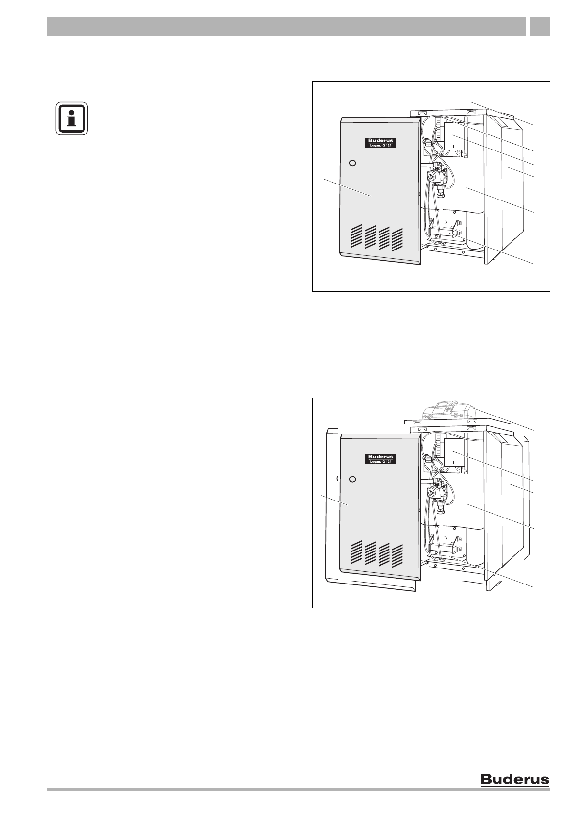
1
Fig. 1 Logano G124X II boiler
1 Boiler front panel
2 Logamatic 2107 control (accessory)
3 Ignition Module
4 Aquastat (control unit)
5 Boiler jacket
6 Boiler block with insulation
7 Burner
2
3
4
5
6
7
1
Fig. 2 Logano G124X SP boiler
1 Boiler front panel
2 Logamatic 2107 control (accessory)
3 Aquastat
4 Boiler jacket
5 Boiler block with insulation
6 Burner
2
3
4
5
6
We reserve the right to make any changes due to technical modifications.
Installation and maintenance instructions Logano G124X II/SP special gas-fired boiler • Issue 04/2005
7
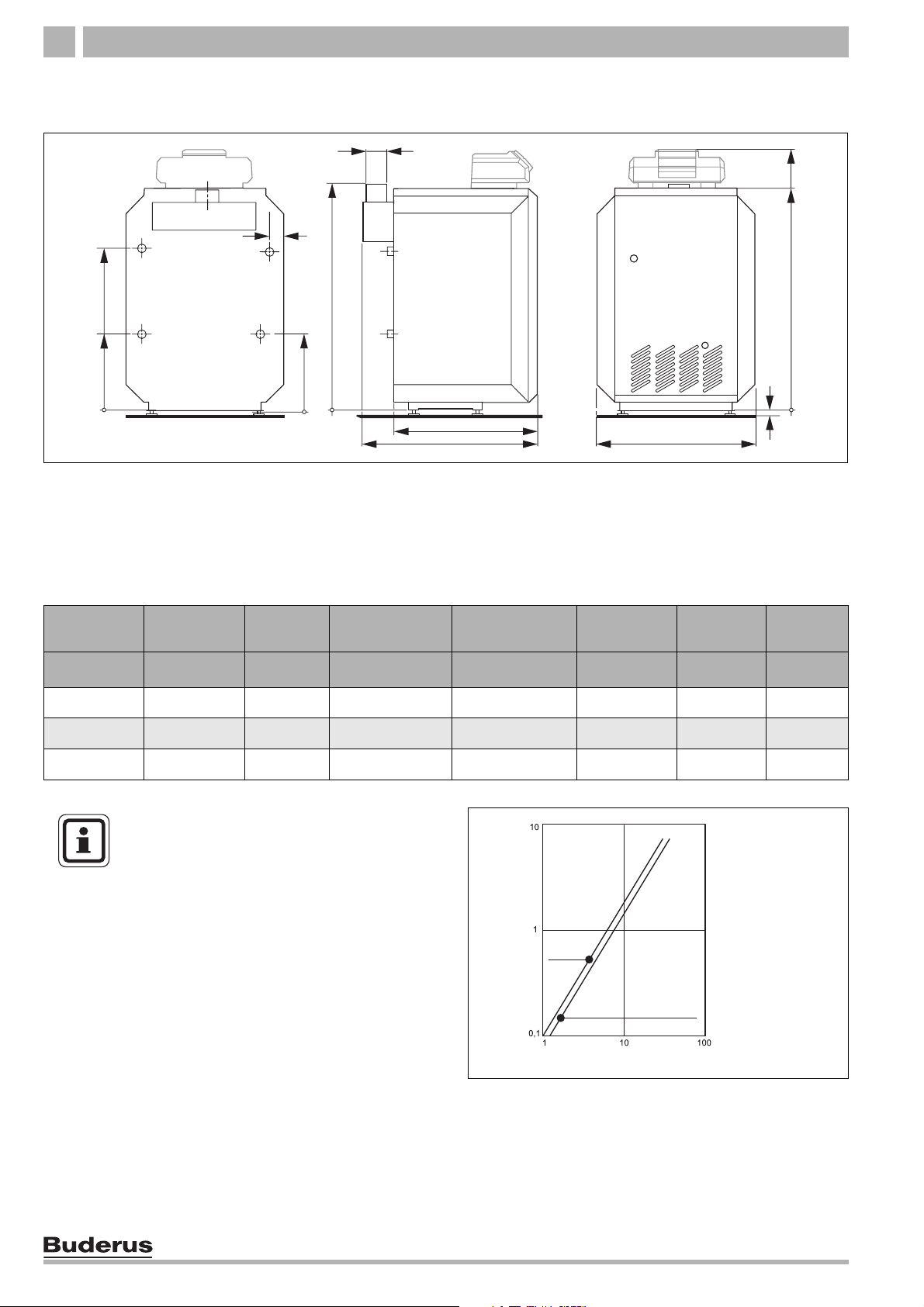
Dimensions and connections3
3 Dimensions and connections
Vent
37"
1 2/5"
23 7/8"
VK 1"
10 7/8"
RK 1"
GAS
EL ¾"
½"
10 7/8"
Fig. 3 Back, side and front view, measurements in inches
Connections (measurements see the following tables):
VK = Boiler supply
RK = Boiler return
EL = Drain
GAS = Gas connection
38 1/2"
33 1/3"
22"
A
23 2/3"
2/3" - 1 2/5"
Boiler size Boiler output A Flue connection
II/SP
Min. overflow
valve capacity
Number of
Nozzles
Water
volume
MBtu/hr Inches Inches lb/hr Qty US gal. lbs
18 74 29 2/5" 5" 62 2 2.4 229
25 103 30 1/5" 5" 86 3 2.9 240
32 132,5 30 7/8" 6" 110 4 3.4 337
Tab. 1 Dimensions
USER NOTE
For the size and dimensions of the main
gas orifices see
Î Chapter 15, page 73.
pressure drop
flow rate in GPM
Empty
weight
Fig. 4 Pressure drop
We reserve the right to make any changes due to technical modifications.
8
Installation and maintenance instructions Logano G124X II/SP special gas-fired boiler • Issue 04/2005
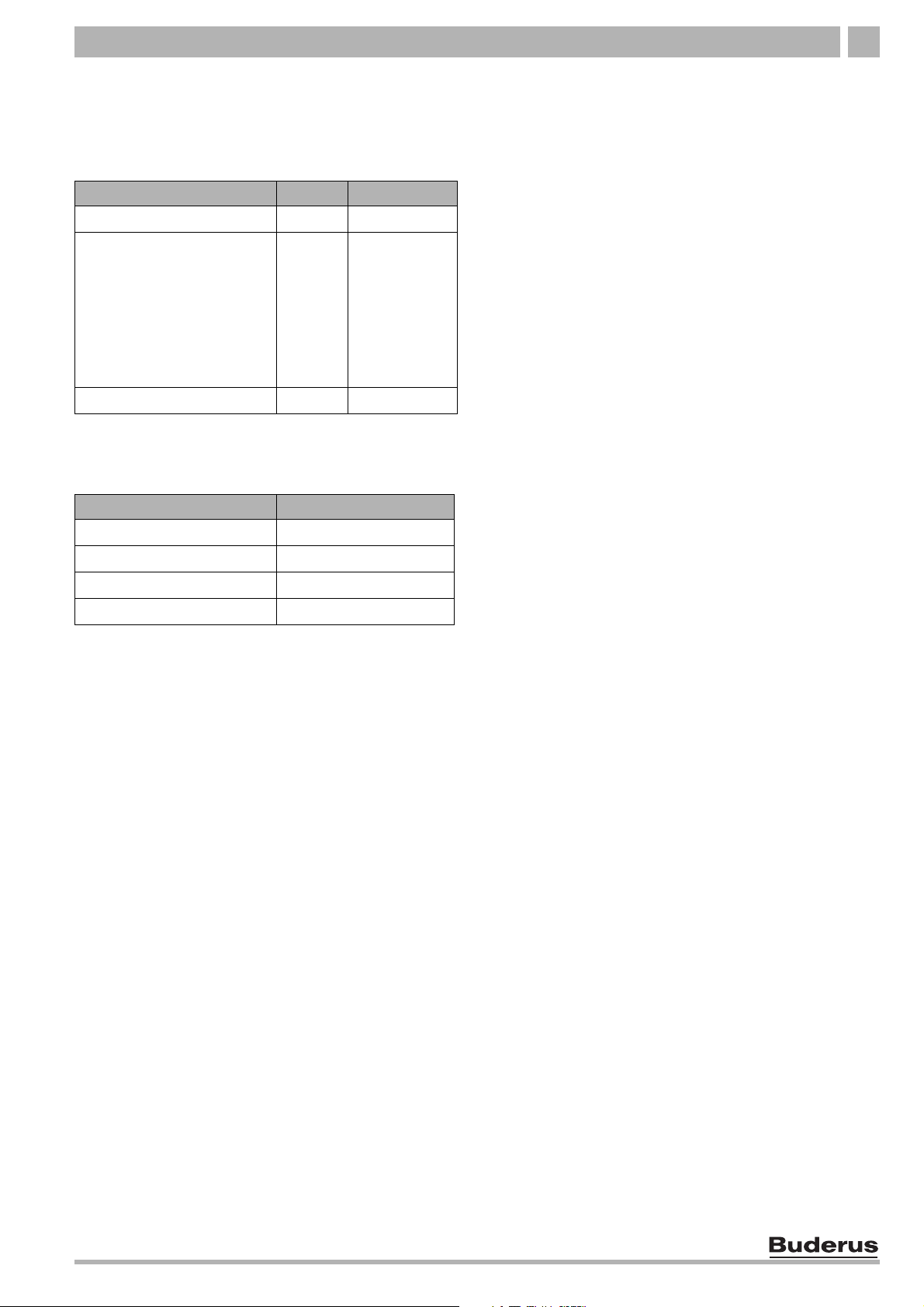
Scope of delivery 4
4 Scope of delivery
z Check packaging on delivery for damage.
z Check delivery for completeness.
Component Qty Packaging
Boiler, complete 1 1 pallet
B-kit components:
- supply manifold
- 30 psi relief valve
- boiler drain (¾")
- pressure/temperature gauge
- 90° elbow (1" NPT)
- 90° elbow (¾" NPT)
- screw-in feet (4)
Technical documents 1 foil package
Tab. 2 Scope of delivery
1
On pallet
1 1 foil package
1
Accessories
Logamatic 2107 control 1
Heat circulation pump 1
Cleaning brush 1
Vertical flue system 1
Tab. 3 Scope of delivery
1
Accessories available by separate order
1
Unit
We reserve the right to make any changes due to technical modifications.
Installation and maintenance instructions Logano G124X II/SP special gas-fired boiler • Issue 04/2005
9

Moving the boiler5
5 Moving the boiler
This chapter describes how to move the boiler safely,
SYSTEM DAMAGE
due to bumps.
CAUTION!
z Check the transport diagrams on the
packaging to protect the sensitive
components from damage by bumping.
USER NOTE
z Protect the boiler connections from dirt
if the boiler is not installed immediately.
USER NOTE
Dispose of the packaging material in an
environmentally compatible fashion.
5.1 Moving the boiler with boiler cart
Move the boiler with packaging and on pallet as much as
possible.
RISK OF INJURY
if the boiler is not properly secured to the
CAUTION!
z Position transport equipment (e.g. boiler cart) at the
back of the boiler.
z Secure boiler to cart.
z Move the boiler to the installation location.
z Remove the straps and the cardboard packaging.
z Remove the bolts from the pallet.
z Lift the boiler at the sides and slide to the edge of the
pallet. Place a pipe under the boiler and roll it on
additional pipes to the installation location.
z Place the boiler in its final position.
trolley.
z Use suitable transport equipment, such
as a boiler cart with a belt.
z Secure the boiler to prevent it from
falling.
Fig. 5 Moving boiler with boiler cart
10
Fig. 6 Moving the boiler
We reserve the right to make any changes due to technical modifications.
Installation and maintenance instructions Logano G124X II/SP special gas-fired boiler • Issue 04/2005

Moving the boiler 5
5.2 Lifting and carrying the boiler
The boiler can be picked up at the hand grips shown.
RISK OF INJURY
due to carrying heavy loads.
CAUTION!
z Lift and carry the boiler with at least four
people at the designated hand grip
positions.
Fig. 7 Lifting and carrying the boiler
We reserve the right to make any changes due to technical modifications.
Installation and maintenance instructions Logano G124X II/SP special gas-fired boiler • Issue 04/2005
11

Placing the boiler6
6 Placing the boiler
This chapter explains how to place the boiler and
position it in the boiler room.
SYSTEM DAMAGE
through frost.
CAUTION!
The boiler is very heavy when full. Check that the floor
can bear the weight before installation.
6.1 Clearances
A space of at least 33 inches is required in front of the
boiler with the door open to allow sufficient access
space for operation and maintenance. When the door is
closed, a minimum clearance of 2 inches is required at
the front and sides, 2 inches clearance is also required
for the flue pipe and 30 inches clearance to the ceiling.
The installation location and the base must be smooth
and horizontal. The boiler may be installed on a
flammable base, but not on carpet.
z Place the boiler in a frost-free room.
min. 6"
2"
3
min.
1
6.2 Leveling the boiler
z Screw the four rubber feet 0.25 to 1.0 inches into the
bottom rails.
z Place boiler on the feet.
z Level boiler horizontally and vertically by screwing
the feet in and out.
min. 2"
33"
Fig. 8 Required clearances in the boiler room
1 Door closed
2 Door open
3 Flue pipe
min. 2"
2
12
Fig. 9 Unscrewing screw-in feet
We reserve the right to make any changes due to technical modifications.
Installation and maintenance instructions Logano G124X II/SP special gas-fired boiler • Issue 04/2005

Boiler installation 7
7 Boiler installation
This chapter describes how to install the boiler. This
includes the following tasks:
– Connecting the heating system
– Electrical connection
– Fuel supply connection
7.1 Preparing for installation
z Unpack all boxes and containers and check all parts
against the packing lists to make sure that everything
has been supplied.
USER NOTE
Every boiler is carefully inspected and
tested before it leaves the factory.
However, if you discover any damage or
missing parts, please inform the supplier
immediately. Before disposing of packing
material, make sure that no parts are still
in it.
We reserve the right to make any changes due to technical modifications.
Installation and maintenance instructions Logano G124X II/SP special gas-fired boiler • Issue 04/2005
13
Boiler installation7
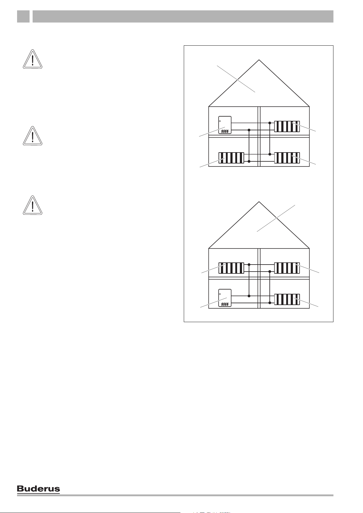
7.2 Connecting the heating system
BOILER DAMAGE
through moisture.
CAUTION!
z Protect the components of the gas
ignition system from moisture (dripping,
spray, rain) during installation of the
boiler, during operation and during
maintenance work (such as replacing
the pump, replacing the control, etc.).
3
CAUTION!
CAUTION!
SYSTEM DAMAGE
due to overheating as a result of low water.
z Note that a boiler installed above the
level of the heating system must be
fitted with a low-water cutoff. The lowwater cutoff must be installed during
installation of the boiler
(Î Fig. 10).
SYSTEM DAMAGE
due to high temperature variations in the
heating system.
z If the boiler is operated in connection
with a refrigeration system, make sure
that the pipes for the refrigerated liquid
are connected in parallel to the boiler
system with suitable valves to prevent
the refrigerated liquid from entering the
boiler.
z The pipe system of a boiler connected
to the heating coils of hot-air heating
systems that may be exposed to the
circulation of cooled air must be fitted
with a flow-control valve or some other
automatic system for preventing the
boiler water from circulating by gravity
during the cooling cycle.
1
2
2
1
Fig. 10 Low-water alarm
1 Boiler
2 Radiator
3 Heating system with low-water cutoff
4 Heating system without low-water cutoff
2
2
4
2
2
14
We reserve the right to make any changes due to technical modifications.
Installation and maintenance instructions Logano G124X II/SP special gas-fired boiler • Issue 04/2005
Boiler installation 7
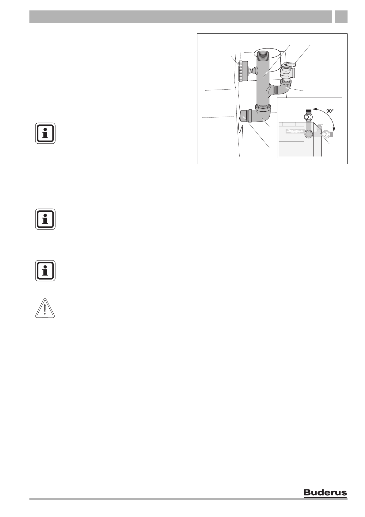
Installation of B-kit
The relief valve and the pressure/temperature gauge are
mounted on the boiler supply VK over the
supply manifold (included in B-kit).
z Seal 90° 1" NPT elbow on VK.
z Seal supply manifold on 90° 1" NPT elbow. The
supply manifold can be mounted vertically or rotated
90° to the right.
z Seal temperature/pressure gauge on supply
manifold.
USER NOTE
Install the relief valve after the leak test
(Î Chapter 7.6, page 23).
The relief valve must be installed in a
vertical position.
The relief valve must also be installed in
accordance with the requirements of the
ANSI/ASME Boiler and Pressure Vessel
Code, Section IV.
USER NOTE
We recommend installing a dirt filter
(accessory) in the heater return
connection to reduce build-up of debris on
the water side.
1
5
6
Fig. 11 Installation of B-kit
1 Pressure/temperature gauge
2 Supply manifold
3 Relief valve 3/4"
4 90° 3/4" elbow
5 90° 1" NPT elbow
6 Boiler supply VK
7 B-kit rotated 90° right
2
3
4
7
CAUTION!
USER NOTE
Observe the local regulations for
connection of boiler systems.
FIRE DANGER
through frost.
z Note that a minimum clearance of two
inches is required between pipes
carrying hot water and flammable walls
in the boiler room.
We reserve the right to make any changes due to technical modifications.
Installation and maintenance instructions Logano G124X II/SP special gas-fired boiler • Issue 04/2005
15
Boiler installation7
7.3 Electrical connection
The electrical connections of the boiler must be
manufactured as specified by the local codes and the
current regulations of the National Electrical Code,
ANSI/NFPA–70.
In Canada the regulations of CSA C 22.1 Canadian
Electrical Code, Part 1, must be observed.
The boiler must be grounded as specified by the
regulations of the relevant local authorities; otherwise
follow the regulations of the National Electrical Code,
ANSI/NFPA–70.
USER NOTE
When making the electrical connections
follow the circuit diagrams on
to Î page 78.
Install an ON/OFF switch near the boiler.
RISK TO LIFE
from electric shock.
WARNING!
z When conducting maintenance work
label all cables before disconnecting
them.
z If cables are connected incorrectly the
system may not operate correctly with
possibly dangerous consequences.
Î page 74
z Check that the heating system functions correctly
after any maintenance work.
16
We reserve the right to make any changes due to technical modifications.
Installation and maintenance instructions Logano G124X II/SP special gas-fired boiler • Issue 04/2005
Boiler installation 7
7.4 Installation of Logamatic 2107 control (accessory)
The boiler is fully functional with the factory-installed
aquastats. The Logamatic 2107 control can also be
installed in addition to the factory-installed aquastats.
USER NOTE
Note the following when making electrical
connections:
z Lay out cables and capillaries carefully.
z Do not bend the capillaries during
installation.
z Never carry out any electrical work on
the heating system unless you are
licensed for this type of work. If you are
not a licensed electrician, have a
specialist electrical company make the
electrical connections.
z Observe the local regulations.
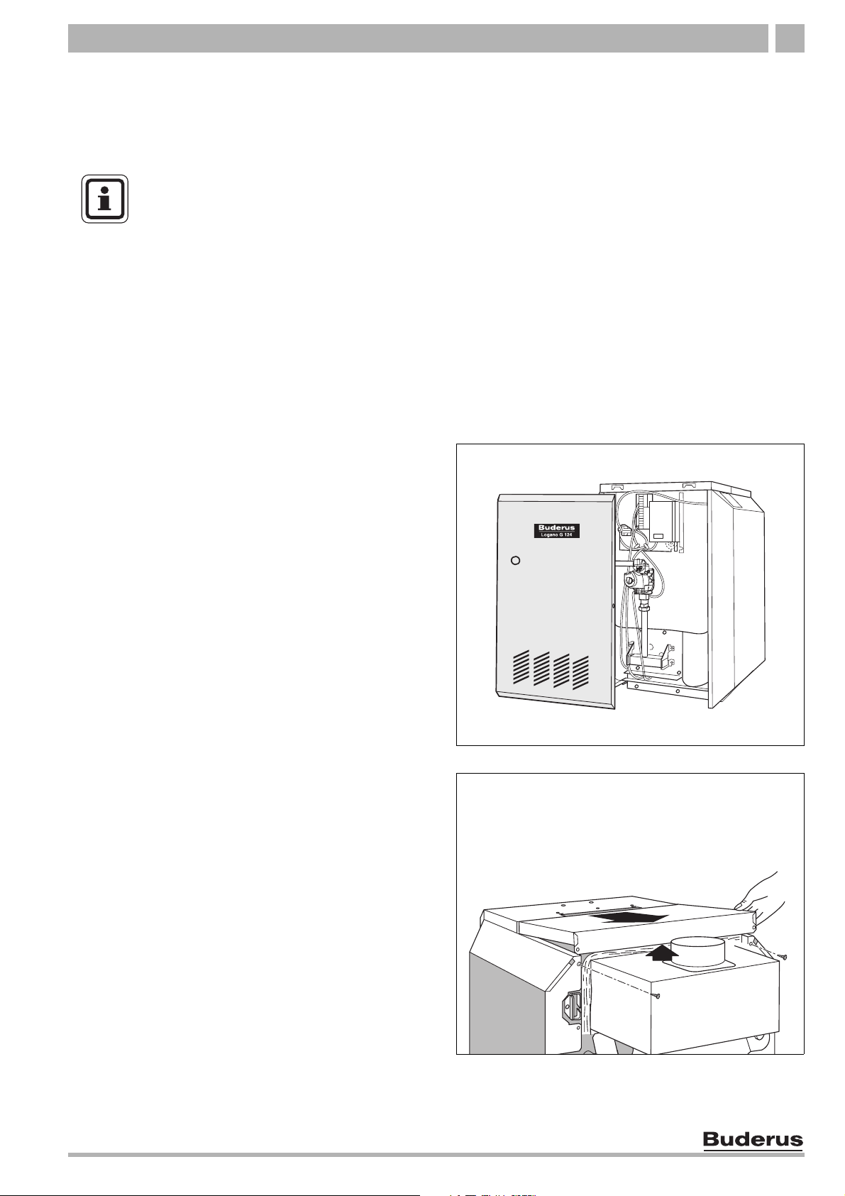
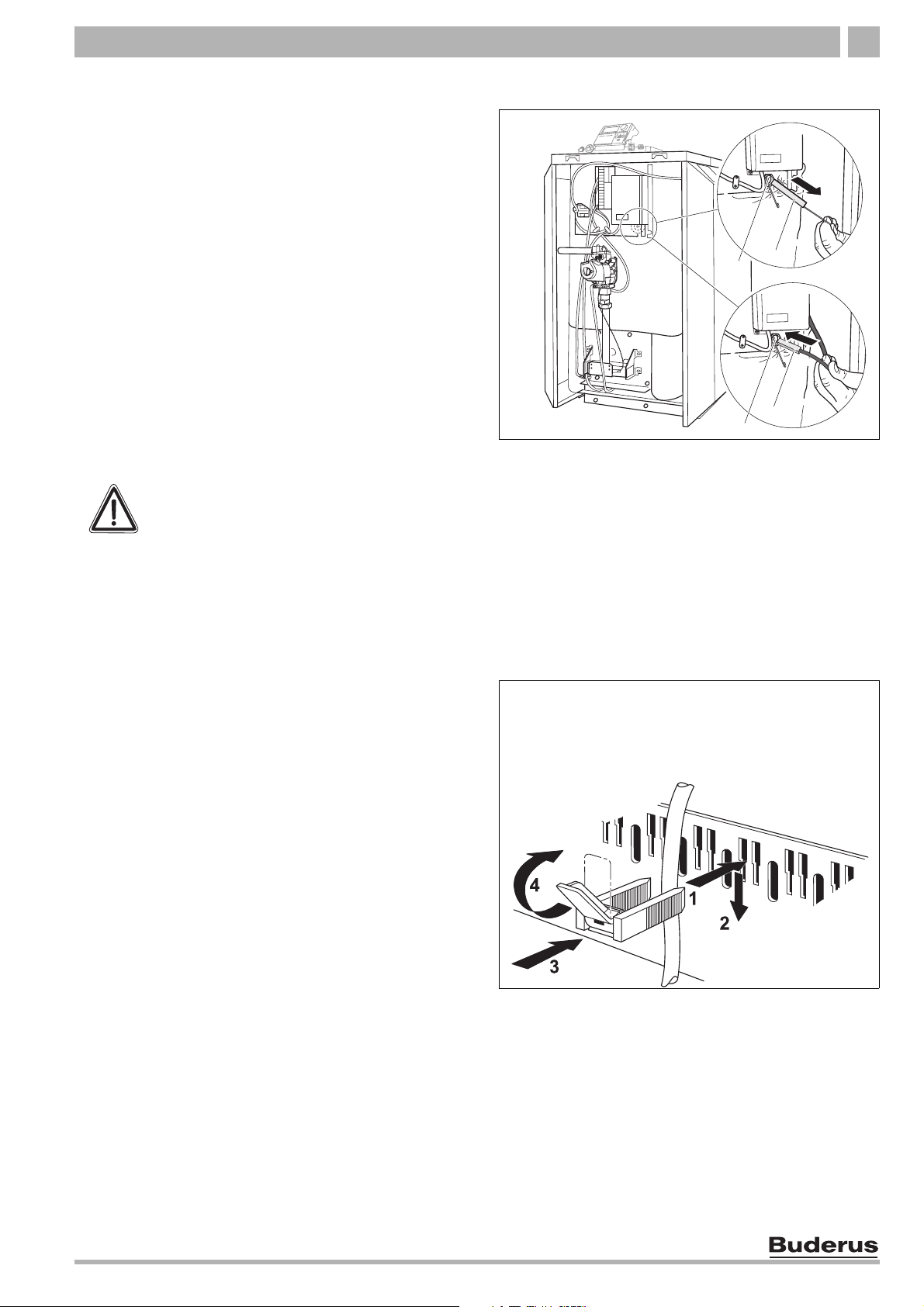
1. Unscrew left and right screws in the side panels, lift
front panel up, pull down and remove to the front.
Fig. 12 Removing front panel of boiler
2. Unscrew the two fastening screws on the back boiler
jacket. Lift the back boiler jacket and remove to the
back.
Fig. 13 Removing boiler jacket
We reserve the right to make any changes due to technical modifications.
Installation and maintenance instructions Logano G124X II/SP special gas-fired boiler • Issue 04/2005
17
Boiler installation7
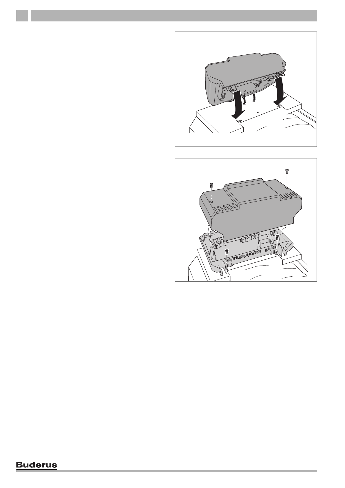
3. Slide the insertion tabs of the control into the oval
openings.
4. Slide control toward the boiler front panel.
5. Push to snap plastic tabs of the control into the
knock-outs.
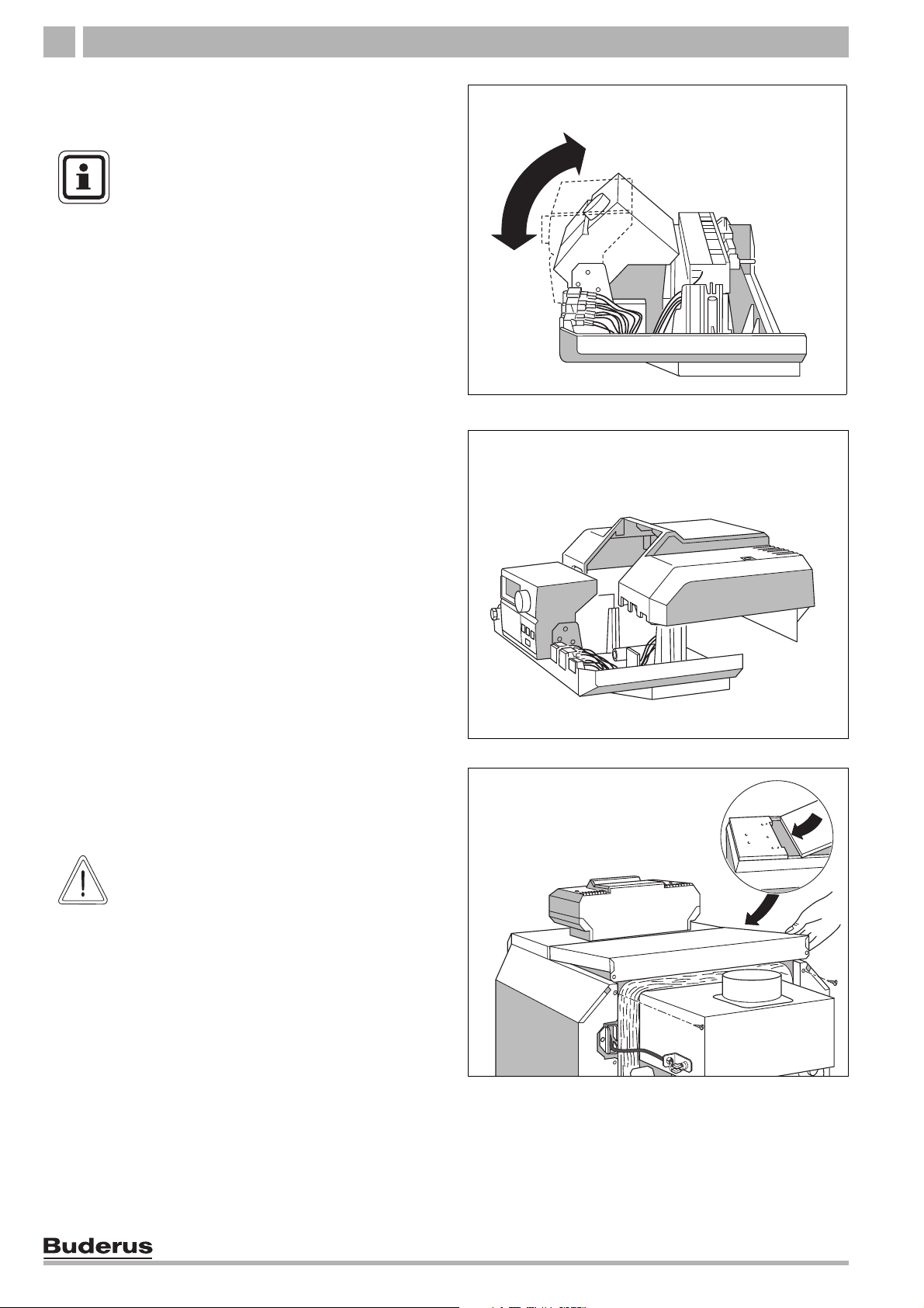
6. Remove top cover of control Remove screws from
the top cover.
Fig. 14 Removing terminal cover
7. Fasten control with sheet-metal screws.
8. Route boiler water sensor cable through the cable
opening and unroll to the required length.
1
Fig. 15 Installation of Logamatic 2000 control system
1 Screws
18
We reserve the right to make any changes due to technical modifications.
Installation and maintenance instructions Logano G124X II/SP special gas-fired boiler • Issue 04/2005
Boiler installation 7
Installation of Logamatic boiler water sensor
9. Trace boiler water capillary package wiring under
the front boiler cover to the measuring point
(immersion well).
10. Remove all spacers from the immersion well.
11. Remove carefully the copper sleeves from the
Logamatic capillaries and slide Logamatic
capillaries together with Honeywell capillary into
boiler immersion well.
12. Press sensor clip (included with control) from the
side or from above to the head of the immersion well.
13. Carefully roll up unnecessary wiring and capillaries
and stow in the Logamatic 2107 control.
Power connection and connections of additional
components
Connect to the power supply as specified by the local
code.
FIRE DANGER
Hot boiler components may damage
WARNING!
electrical wiring.
z Make sure that all cables are routed in
the ducts or on the boiler insulation.
Fig. 16 Front of boiler
1 Measuring point (immersion well)
2 Spacers (blanking piece)
3 Boiler water sensor (Logamatic 2107 control)
2
1
3
1
14. Route all wiring to the control through the wiring
opening and connect as specified by the circuit
diagram.
Install strain relief
Secure all wiring with wiring clips (included with control):
– Insert wiring clip with wiring from above into the slot
of the clip frame; the lever bar must point upwards
(step 1).
– Slide wiring clip down (step 2).
– Press (step 3).
– Move lever up (step 4).
1
Fig. 17 Secure wiring with wiring clip
We reserve the right to make any changes due to technical modifications.
Installation and maintenance instructions Logano G124X II/SP special gas-fired boiler • Issue 04/2005
19
Boiler installation7
Install panel components
15. Swivel display unit to the desired position.
USER NOTE
We recommend positioning the display
unit straight on combinations with an Ltank.
16. Position terminal cover and screw to control.
Fig. 18 Swivel display unit
17. Slide tabs of rear boiler cover under the front boiler
cover and press down at back.
18. Screw rear boiler cover to rear panel of boiler.
SYSTEM DAMAGE
due to dirt.
CAUTION!
If the boiler is assembled and not in use,
note the following:
z Protect the boiler connections from dirt
by closing the connections.
Fig. 19 Positioning terminal cover
Fig. 20 Installing rear boiler cover
20
We reserve the right to make any changes due to technical modifications.
Installation and maintenance instructions Logano G124X II/SP special gas-fired boiler • Issue 04/2005
Boiler installation 7
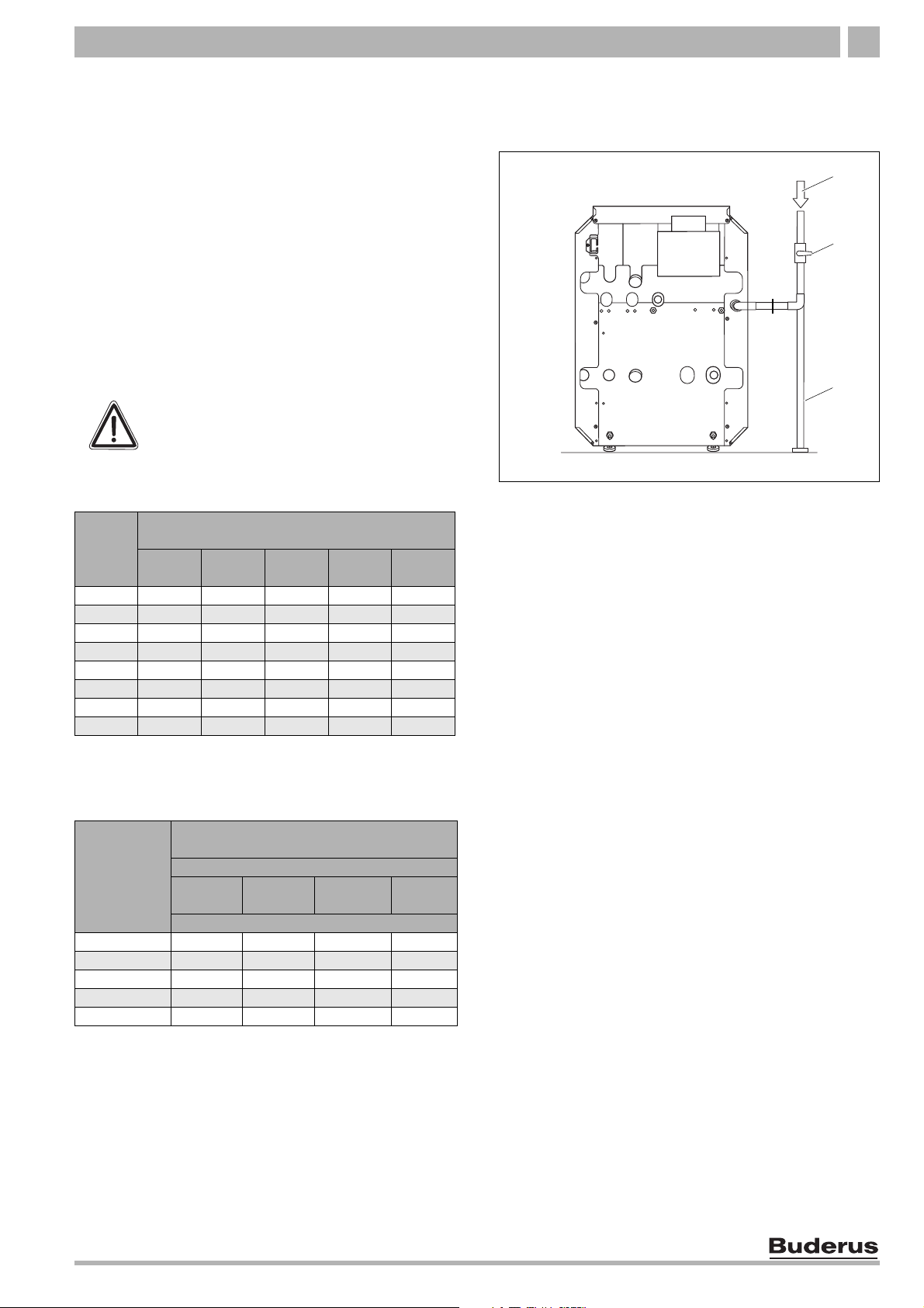
7.5 Fuel supply connection
7.5.1 Gas connections
For the gas pipe diameter required for the installation
please see
Tab. 4 and Tab. 5. Make sure that the pipe
fitting has the correct thread size.
Make sure that a sediment trap is installed at the inlet for
the gas supply pipe to the boiler. A gas cock shut-off
must be installed outside the boiler jacket if required by
the local code. We recommend installing a gas cock
shut-off in the main gas pipe to the boiler. The gas pipe
must be fastened outside the boiler.
The local codes must be observed during installation of
the gas connection, otherwise the regulations of the
National Fuel Gas Code, ANSI Z 223.1.
DANGER OF EXPLOSION
Leakage from the gas pipes and gas
WARNING!
connections may cause an explosion.
z Use soap solution to find leaks.
Length
Ironpipe
in feet
Gas pipe supply volume in cubic feet of gas
of
per hour
1
1/2 3/4 1 1 1/4 1 1/2
10 132 278 520 1060 1600
20 92 190 350 730 1100
30 73 152 285 590 890
40 63 130 245 500 760
50 56 115 215 440 670
75 45 93 175 360 545
100 38 79 160 305 480
150 31 64 120 250 380
Tab. 4 Gas pipe supply volume
1 Maximum gas supply volume in cubic feet per hour, based on a
specific gas weight of 0.60 and a gas pressure of 0.5 psi or less
and a pressure rise corresponding to a water column of 0.3
inches.
Equivalent lengths for pipe fittings in
Nominal
diameter of
iron pipe
(inches)
90° angle T-piece Ball valve
feet
Pipe fitting type
Gas
valve
Equivalent lengths in feet
1/2 1.4 2.7 0.3 0.80
3/4 2.1 4.1 0.5 1.25
1 2.6 5.2 0.6 1.6
1 1/4 3.5 6.9 0.8 2.15
1 1/2 4.0 8.0 0.9 2.50
Tab. 5 Equivalent lengths for pipe fittings
Disconnect the boiler with the gas shut-off rom the gas
supply pipe system the system is pressure tested with a
test pressure greater than 1/2 psi.
Fig. 21 Pipe connection to gas fittings – back view
1 Gas supply
2 Shut-off
3 Sediment trap
1
2
3
We reserve the right to make any changes due to technical modifications.
Installation and maintenance instructions Logano G124X II/SP special gas-fired boiler • Issue 04/2005
21
Boiler installation7
If the gas supply pipe system is pressure tested at a test
pressure of 1/2 psi or less, it is sufficient to disconnect
the boiler from the pipe system by closing the stop valve.
z The boiler and its gas connections must be tested for
leaks before placing it into operation,
Use only sealant that is resistant to corrosion by LPG for
pipe connection. Only a small amount of sealant must be
applied to the external thread of the pipe connections.
If you wish to convert the boiler to propane, please
contact Buderus for the required conversion
components. Do not attempt to convert the boiler without
the approved Buderus parts and the relevant technical
documentation. The technical documentation is
included with the conversion parts.
7.5.2 Installation at high altitudes
The boiler is designed for installation at altitudes below
8500 feet above sea level. The boiler must be converted
appropriately for installation above altitudes of 8500
feet. The conversion consists of replacing the main gas
nozzles.
(Î page 29).
USER NOTE
If the installation location is over 8500 feet
above sea level, please contact Buderus
for the required conversion components.
Do not attempt to convert the boiler
without the approved Buderus parts and
the relevant technical documentation.
The technical documentation is included with the
conversion parts (accessory).
22
We reserve the right to make any changes due to technical modifications.
Installation and maintenance instructions Logano G124X II/SP special gas-fired boiler • Issue 04/2005
Boiler installation 7
7.6 Filling heating system and checking for leaks
The boiler is tested for leaks at the factory. Before
placing the heating system tank into use, check it for
soundness to avoid leaks occurring during operation.
Water treatment
USER NOTE
Have the water analyzed before filling the
heating system. The water may require
treatment as a result of the analysis.
Please consult the local water supply
company if the water is extremely hard or
CAUTION!
has a pH level below 7.0.
SYSTEM DAMAGE
due to overpressure during the leak test.
Pressure, control or safety components
may be damaged by high pressure.
z Before conducting the leak test make
sure that no pressure, control or safety
components that cannot be
disconnected from the water
compartment of the boiler are installed.
Fig. 22 Temperature/pressure gauge
Carry out the leak test at 1.5 times the normal operating
pressure and as specified by the local codes as follows:
Maximum
operating pressure
30 psi (with the included relief
valve)
58 psi (with a different relief
valve)
Tab. 6 Test pressures
Maximum
construction site test
pressure
45 psi
75 psi
z Close connection for relief valve (Î Fig. 11,
page 15) and all other open connections with plugs.
z Disconnect the expansion tank from the system by
closing the cap valve.
z Open mixing and stop valves on hot water side.
z Fill boiler slowly with water from the building
connection.
z Turn cap of automatic vent one revolution to allow the
air to escape.
z Slowly fill heating system. Observe pressure display
on pressure gauge during this process.
z Check connections and pipes for leaks.
z Bleed heating system through the bleed valves on
the radiators.
z If the pressure falls while bleeding, water must be
added.
z Install relief valve (Î Fig. 11, page 15).
We reserve the right to make any changes due to technical modifications.
Installation and maintenance instructions Logano G124X II/SP special gas-fired boiler • Issue 04/2005
23
Check openings for combustion air supply and venting8
8 Check openings for combustion air supply and venting
BOILER DAMAGE AND OPERATING
FAULTS
CAUTION!
due to missing or inadequate openings for
combustion air and venting of the boiler
room.
Inadequate venting of the boiler room may
result in excessive ambient temperatures.
This can damage the boiler.
Inadequate combustion air supply may
cause operating faults.
z Make sure that inlets and outlets are
not reduced or closed and that they are
adequately dimensioned.
z If faults are not corrected immediately,
the boiler must not be operated.
z Inform the system operator of the fault
and the danger.
To ensure an adequate combustion air supply and
venting of the heating system suitable measures must
be taken in accordance with the National Fuel Gas
Code, Section 5.3, Air for Combustion and Ventilation,
or the local codes.
In Canada the regulations in accordance with the
CSA/CGA–B 149.1 or 2 Installation Codes apply.
BOILER DAMAGE
due to contaminated combustion air.
CAUTION!
z Never use cleaning agents that contain
chlorine and halogenated
hydrocarbons (e.g. spray bottles,
solvents and cleaning agents, paints,
glues).
z Do not store or use these substances in
the boiler room.
z Prevent excessive dust levels.
Total air supply from inside the building
Make sure that the boiler room has two permanent
openings that are connected with one or more other
rooms. When calculating the cross-section areas of the
openings, the total combustion output of all gas-fired
appliances in the connected rooms must be taken into
account. Each opening must have a minimum crosssection of one square inch per 1000 Btu/h of the total
combustion output of all gas-fired appliances inside the
connected rooms. Note that the minimum cross-section
of every opening must not be less than 100 square
inches. One opening must not be more than 12 inches
from the ceiling and the other must not be more than 12
inches from the floor of the boiler room, calculated from
the outer edge of the opening. The shortest dimension
of all inlet and outlet openings must not be less than
three inches.
Total air supply from outside the building
Make sure that the boiler room has two permanent
openings, one of which must not be more than 12 inches
from the ceiling and the other must not be more than 12
inches from the floor of the boiler room, calculated from
the outer edge of the opening. The openings have a
direct connection or a connection through ventilation
ducts to the outside or to rooms that have an
unobstructed connection to the outside (crawl space or
attic). The shortest dimension of all inlet and outlet
openings must not be less than three inches.
1. If there is a direct connection to the outside, each
opening must have a minimum cross-section of one
square inch per 4000 Btu/h of the total combustion
output of all gas-fired appliances inside the closed
room.
2. If there is a connection to the outside through
vertical ventilation ducts, each opening must have a
minimum cross-section of one square inch per 4000
Btu/h of the total combustion output of all gas-fired
appliances inside the closed room.
WARNING!
24
3. If there is a connection to the outside through
FIRE DANGER
due to flammable materials or liquids.
z Do not store flammable materials or
horizontal ventilation ducts, each opening must have
a minimum cross-section of one square inch per
2000 Btu/h of the total combustion output of all gasfired appliances inside the closed room.
liquids in the immediate vicinity of the
heat generator.
4. If the openings are connected to ventilation ducts,
the ducts must have the same cross-section area as
the openings.
We reserve the right to make any changes due to technical modifications.
Installation and maintenance instructions Logano G124X II/SP special gas-fired boiler • Issue 04/2005
 Loading...