

Buderus Logano G115 WS US/CA, Logano G115/3 WS, Logano G115/4 WS, Logano G115/5 WS Installation And Service Instructions Manual
For heating contractors
Please read carefully prior
to installation and servicing.
Caution!
Observe the safety instructions of this installation
and maintenance manual before placing the boiler
in operation.
Danger!
If installation, adjustment, modification, operation or
maintenance of the heating system is carried out by
an unqualified person, this may result in danger to
life and limb or property damage.
The directions of this installation and maintenance
manual must be followed precisely.
Contact a qualified service company or service provider if support or additional information is required.
Caution!
The operating manual is a component of the technical documentation and must be handed over to the
operator of the heating system.
Discuss the content of this manual with the owner
or operator of the heating system to ensure that
they are familiar with all information required for
operation of the heating system.
Installation and Service
Instructions
Low-temperature
oil boiler
6 720 615 225-00.1RS
Logano G115 WS US/CA
6 720 615 225 - 08/2007 US/CA

Contents
Logano G115 WS US/CA - Technical specifications are subject to change without prior notice.
2
Contents
1 Safety Considerations and Symbol
Descriptions 3
1.1 Regarding this Manual 3
1.2 Explanation of symbols 3
1.3 Observe the following Symbols 3
1.3.1 Installation Guidelines 4
1.3.2 Boiler Room Guidelines 4
1.4 Tools, Materials and Accessories 4
1.5 Disposal 4
2 Product description 5
2.1 Intended use 5
2.2 Certification and testing mark 5
2.3 Notes on installation and operation 5
2.4 Heating system water quality 5
2.5 Product description 6
2.6 Pack contents 7
2.7 Dimensions Specifications 8
2.7.1 Logano G115 WS dimensions 8
2.8 Conditions for operation 9
2.8.1 General operating conditions 9
2.8.2 Conditions for the boiler room and the
environment 10
2.8.3 Combustion air supply conditions 10
2.8.4 Conditions, Fuel 10
2.8.5 Conditions power supply 11
2.8.6 Conditions for hydraulic system and
water quality 11
3Moving the boiler 12
3.1 Reducing boiler weight for transportation
purposes 12
3.2 Lifting and carrying the boiler 13
3.3 Using transportation aids to transport
the boiler 13
4 Installing the boiler 14
4.1 Wall clearances 14
4.2 Reversing boiler door 15
4.3 Mounting the adjustable feet
(included with B-kit) 16
4.4 Positioning and leveling the boiler 16
5 Installing the boiler 17
5.1 Flue pipe installation 17
5.1.1 Chimney venting 17
5.2 Fitting the water connections 19
5.2.1 Fitting the B-kit 19
5.2.2 Installation of boiler drain (included in B-Kit) 20
5.2.3 Installing system components 20
5.3 Filling the heating system and checking
for leaks 21
5.4 Mounting the burner 23
5.5 Connecting the fuel supply 23
5.6 Installing aquastat 24
5.7 Blocked vent switch (required in Canada) 24
5.8 Electrical connections 24
5.8.1 Fitting the controls 25
5.8.2 Fitting temperature sensor assembly
and burner cable 26
5.8.3 Connecting the power supply and additional
components 27
5.8.4 Fitting cable ties 27
5.9 Fitting outer casing panels 27
6 Commissioning the heating system 28
6.1 Bringing the system up to operating pressure 28
6.2 Checking the safety valve 28
6.3 Checking position of heat exchanger baffles 29
6.4 Preparing the heating system for operation 29
6.5 Starting up the control and the burner 29
6.6 Notes on commissioning the burner 30
6.7 Raising flue gas temperature 30
6.7.1 Adjusting the position of heat exchanger
baffles 31
6.7.2 Removing heat exchanger baffles 31
6.7.3 Removing the heat exchanger barrier plate 32
6.8 Manual reset high limit (STB) 32
6.9 Installing the burner door jacket 32
6.10 Commissioning log 33
7 Shutting down the heating system 34
7.1 Shutting down normally 34
7.2 Shutting down the heating system in an
emergency 34
7.2.1 What to do in an emergency 34
8 Heating system servicing 35
8.1 Why is regular maintenance important? 35
8.2 Preparing the boiler for servicing 35
8.3 Cleaning the boiler 36
8.3.1 Cleaning the boiler with brushes 36
8.3.2 Wet cleaning (chemical cleaning) 37
8.4 Checking heating system operating pressure 37
8.5 Testing relief valve 38
8.6 Servicing and maintenance logs 39
9 Troubleshooting 42
10 Installation examples 43
11 Parts lists 45
12 Circuit diagrams 50
1
Safety Considerations and Symbol Descriptions
Logano G115 WS US/CA - Technical specifications are subject to change without prior notice.
3
1 Safety Considerations and Symbol Descriptions
1.1 Regarding this Manual
This document contains important information regarding
safe and proper installation, operation and maintenance of
the boiler.
The high tech G115 WS boiler is designated as a hot
water heating boiler.
The Installation and Maintenance Instructions are directed
to the installing contractor who has professional knowledge regarding boiler installation and maintenance.
1.2 Explanation of symbols
Signal words are used to indicate the seriousness of the
ensuing risk if measures for minimising damage are not
taken.
– Caution indicates that minor damage to property may
occur.
– Warning indicates that minor personal injury or severe
damage to property may occur.
– Danger means that severe personal injury may occur.
Very serious cases may result in death.
Notes contain important additional information.
Notes do not contain any warnings or information about
hazards or risks.
1.3 Observe the following Symbols
All applicable local, state, and national codes and regulations must be observed for the installation of the boiler:
– The local building code requirements regarding place-
ment, combustion air and venting and chimney system
must be followed.
– Follow applicable electrical code requirements.
– Follow the local code and standards regarding safe
boiler operation.
Warnings are indicated by a warning triangle
and a grey background.
Notes are identified in the text by this symbol.
They are bounded by horizontal lines above
and below the text.
NOTICE
Use only original Buderus spare parts.
Buderus can not be held liable for damage
caused by non-Buderus parts.
NOTICE
The boiler installation must be performed by
a qualified installer in accordance with regulations put forth in NFPA-31 Installation of
Oil-Burning Equipment. The installation must
comply with all local and national codes, regulations and authorities having jurisdiction regarding the installation of oil fired boilers.
For Canada refer to the guidelines of CSA/
CGA-B139 Installation Codes.
1
Safety Considerations and Symbol Descriptions
Logano G115 WS US/CA - Technical specifications are subject to change without prior notice.
4
1.3.1 Installation Guidelines
1.3.2 Boiler Room Guidelines
1.4 Tools, Materials and Accessories
For the installation and maintenance of the boiler you will
need typical tools used in this industry.
In addition, the following components are useful:
– Hand truck with strap or Buderus boiler cart.
– Wood blocking.
– Cleaning brushes and/or chemical cleaning agents for
wet cleaning.
1.5 Disposal
V Please dispose of any trash in an environmentaly
friendly fashion.
V Please discard properly of any heating system related
components.
Caution: DANGER TO LIFE
from electric shock.
V Do not work on electrical components un-
less you have the required qualification.
V Do not work on electrical components un-
less you have the required qualification.
V Prior to opening the control: shut down
the power supply by turning off the emergency shut-off switch or disengaging the
heating system circuit breaker, and prevent from accidental reactivation.
V Observe all applicable installation guide-
lines.
Caution: DANGER TO LIFE
from flue gas poisoning.
Insufficient combustion air can result in dangerous operation if combustion air is taken
from indoors.
V Please observe that combustion air open-
ings are not reduced in size or closed.
V Make sure that no mechanical air open-
ings or devices remove combustion air
from the boiler room such as central vacuum systems, dryers and air conditioning
appliances.
V Make sure that the boiler is connected to
a chimney or horizontal venting system
that is capable of handling the slight positive breeching pressure.
V If any of these problems have not been
corrected, the boiler must not be operated.
V Make the end-user aware of these guide-
lines and their potential danger.
Caution: FIRE DANGER
due to flammable or liquid materials.
V Make sure that flammable and liquid mate-
rials are not stored in the close vicinity of
the boiler.
2
Product description
Logano G115 WS US/CA - Technical specifications are subject to change without prior notice.
5
2 Product description
This installation and maintenance manual contains important information for the safe and intended installation, initial start-up and maintenance of this boiler.
The special oil fired boiler Logano G115 WS is generally
referred to below as a boiler.
The installation and maintenance manual is provided for
technicians who have been trained and have experience
in working with heating systems and oil fired installations.
2.1 Intended use
The G115 WS is designed for central heating and
domestic hot water (DHW) systems, for instance in residential homes or apartment buildings, or small commercial applications.
2.2 Certification and testing mark
This appliance has been tested and certified to meet rules
and regulations in place for the US and Canadian markets.
2.3 Notes on installation and operation
When installing and operating the heating system, it is the
installer's responsibility to meet all applicable federal,
state, and local codes.
2.4 Heating system water quality
Poor water quality can damage heating systems due to
scale formation and corrosion.
Please refer to Chapter 2.8.6, Tab. 9 for further details of
the water quality.
Caution: Risk of system damage due to unsuitable boiler water.
V If oxygen-permeable pipes are used, e.g.
for radiant heating systems, the systems
must be separated from the boiler by a
heat exchanger. Unsuitable heating system water promotes sludge formation and
corrosion. This can result in heating system malfunction and boiler damage.
2
Product description
Logano G115 WS US/CA - Technical specifications are subject to change without prior notice.
6
2.5 Product description
The boiler is a low-temperature oil-fired appliance with
automatic control panel or aquastat for boiler water temperature.
The boiler consists of:
– Boiler heat exchanger with insulation
– Boiler jacket
– Control panel or aquastat
The controls monitor and control all electrical boiler components.
The boiler can alternatively be fitted with a simple aquastat control.
The boiler jacket prevents heat loss and acts as a noise
insulator.
The boiler heat exchanger transfers the heat generated by
the burner to the heating water. The insulation prevents
energy loss.
Suitable burners
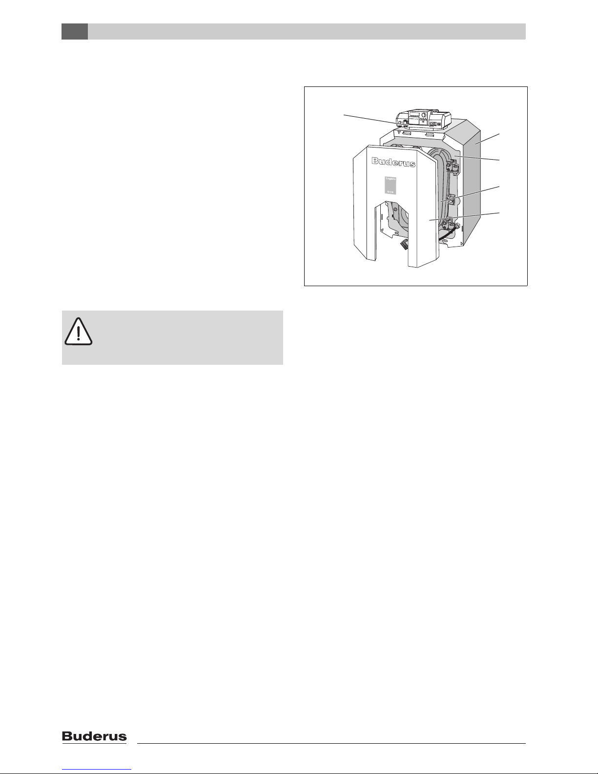
Fig. 1 Boiler without burner
1 Control panel
2 Boiler jacket
3 Boiler heat exchanger with insulation
4 Burner door
5 Burner door panel
Caution: Risk of system damage from use
of incorrect burner.
V Only the burner provided may be em-
ployed with this boiler.
6 720 615 225-01.1RS
1
2
3
4
5
2
Product description
Logano G115 WS US/CA - Technical specifications are subject to change without prior notice.
7
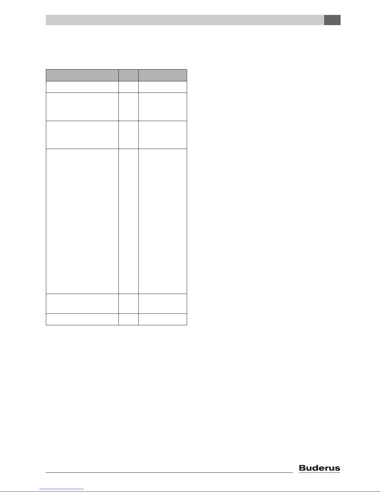
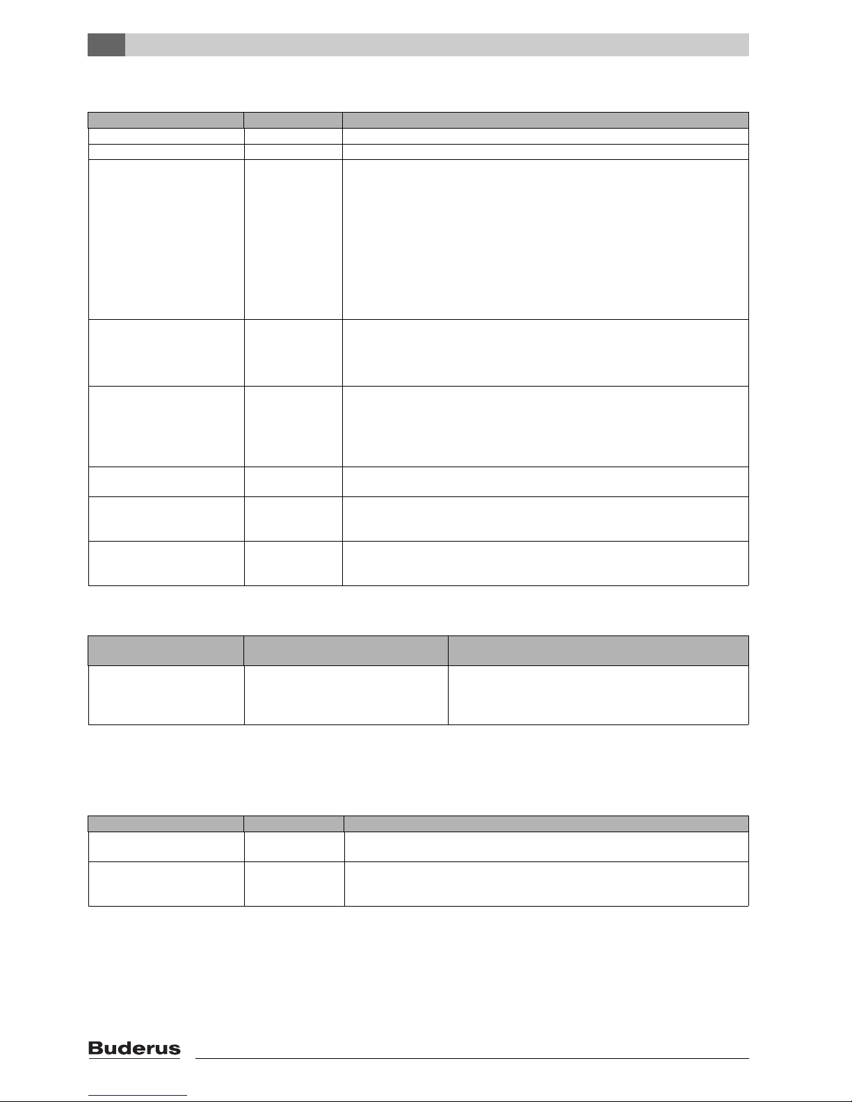
2.6 Pack contents
Upon delivery, check that the packaging is complete and
undamaged.
Component Qty Packaging
Boiler heat exchanger 1 1 pallet
Boiler casing, factory-fitted to boiler heat
exchanger
Burner door and burner
door panel, factory-fitted
to boiler heat exchanger
B-kit components:
– 1 Supply manifold
G115"US"
– elbow 90 ° 1-1/4"
– elbow 90 ° 3/4"
– double nipple R1-1/4"-
1-1/4" NPT x 75
– boiler drain 3/4"
– relief valve 3/4" x 3/4"
30PSI
– temperature/pressure
gauge
– Bolt set B-Kit
G115"US"
– adjustable boiler feet
M10 x 51 packed
1 1 foil package
1)
1) in the combustion chamber in the boiler
Controller or, alternatively,
Aquastat
2)
2) Aquastat may be supplied with burner
11 box
Technical documentation 1 foil package
Tab. 1 Package Contents
2
Product description
Logano G115 WS US/CA - Technical specifications are subject to change without prior notice.
8
2.7 Dimensions Specifications
2.7.1 Logano G115 WS dimensions
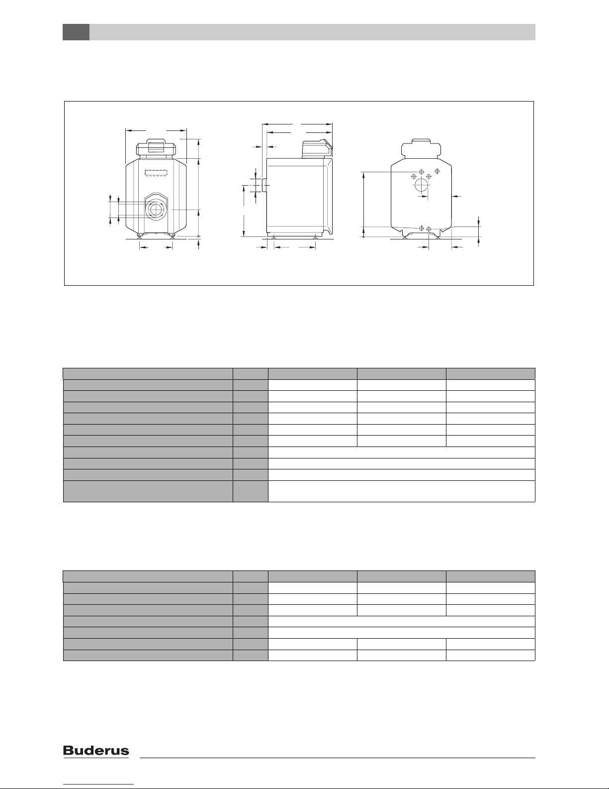
Fig. 2 Connections and dimensions (measurements in inches)
VK = Boiler supply
RK = Boiler return
EL = Boiler drain (connection for drain valve)
Connections and dimensions:
7 747 019 141-02.1RS
23
5/8"
L
VK
L
K
F
L
39
5/8"
30
3/8"
1
3/4"
2
7/8"
8
7/8"
8
7/8"
Rp1
1/4"
EL
Rp
3/4"2 7/8"
25
1/4"
RK
1" NPT
3
1/4"
Ø 5"
20"
10
3/8"
12
1/4"
5
7/8"
4
3/8"
5/8"
- 1"
Boiler model Unit G115/3 WS G115/4 WS G115/5 WS
Boiler sections 345
Heating capacity (gross output) MBtu/hr 85 109 136
Thermal output (net IBR output) MBtu/hr 74 95 119
Boiler water content Gal 8.7 10.8 12.9
Gas capacity cu.ft. 1.20 1.75 2.21
Oil firing rate GPH 0.7 0.9 1.0
Flue gas back-pressure W.C. 0.04" - 0.06"
Permissible flow temperatureSafety
1)
1) Limit (safety temperature limiter, STB)
Maximum permitted flow temperature = Safety limit (STB) - 32 °F
Example: Safety limit (STB) = 212 °F, maximum permitted flow temperature = 212 ° - 32 ° = 180 °F
The safety limit must meet the national regulations of the country concerned.
°F 230
Allowable operating pressure psi 58
Maximum time constant of thermostat and
high limit safety cut-out (STB)
s 40
Tab. 2 Technical data for boilers without burners
Boiler model Unit G115/3 WS G115/4 WS G115/5 WS
Boiler overall length (L) Inch 23-5/8" 28-5/8" 33-3/8"
Boiler block length (LK) Inch 21-1/8" 25-¾" 30-½"
Combustion chamber length Inch 16" 20-½" 25-¼"
Combustion chamber length Inch 10-5/8"
Burner door thickness Inch 3-5/8"
Distance between boiler feet (FL) Inch 10-3/8" 16-1/8" 20-7/8"
Net weight1)– Lbs 330 403 476
Tab. 3 Dimensions, weight and other data for boilers without burners
1) Incl. packaging material approx. 6-8 % more
2
Product description
Logano G115 WS US/CA - Technical specifications are subject to change without prior notice.
9
2.8 Conditions for operation
Maintaining the specified operating conditions will enable
the boiler to provide a high level of reliability and long service life. Some details relate only to operation with Buderus
Logamatic control panels.
2.8.1 General operating conditions
Caution: Ri sk of sys te m da ma ge if op er at in g
conditions are not maintained.
Irreversible damage to individual compo-
nents of the boiler as a whole or the heating
system may occur.
V The information on the rating plate is bind-
ing and must be observed.
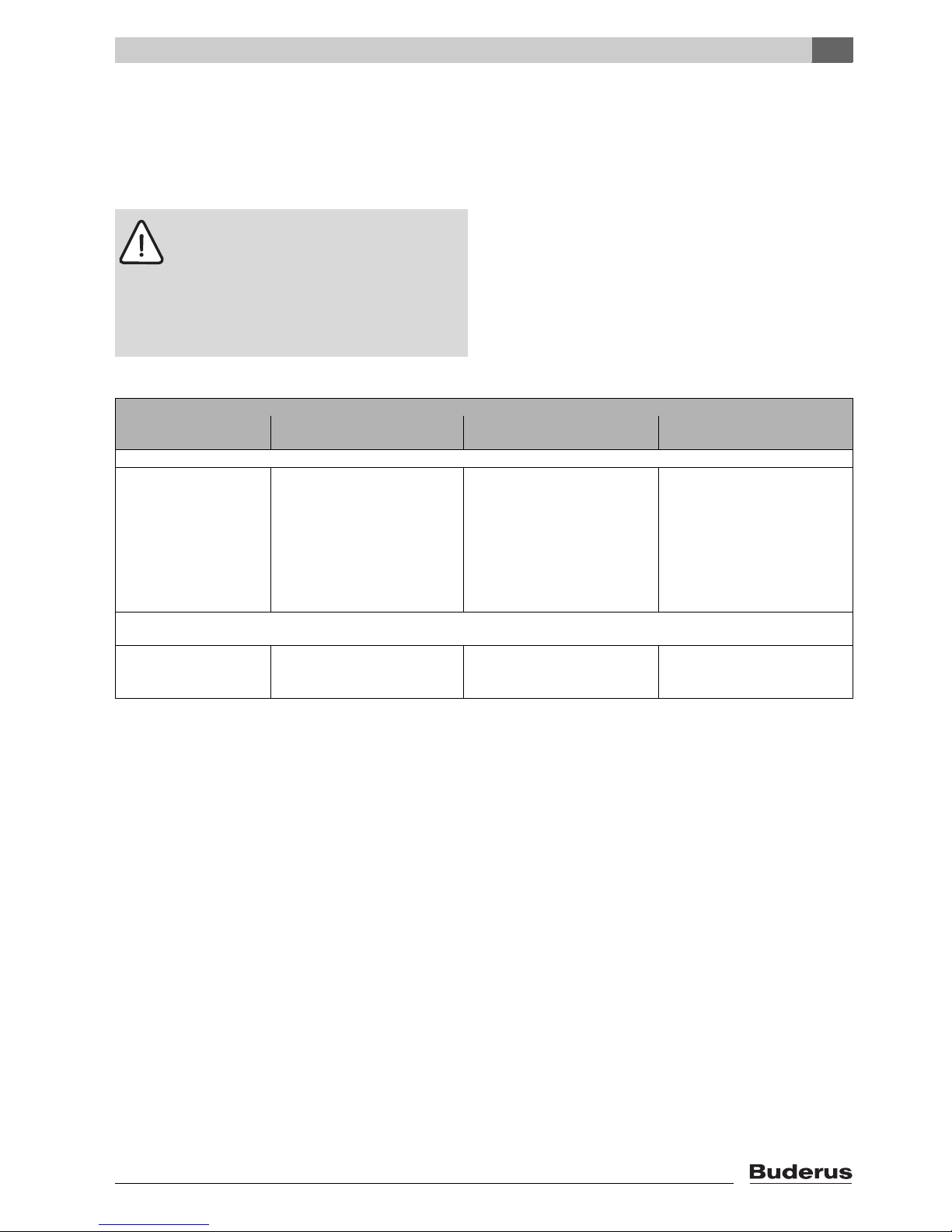
Operating conditions
Min. boiler water tempera-
ture
Operating interruption
(complete boiler shutdown)
heating circuit with
heating circuit mixing valve
1)
Min. return temperature
In combination with Logamatic control for variable low-temperature operating modes, such as Logamatic 2107
no requirements operating
temperatures are ensured by
the Logamatic controls
2)
Automatically by Logamatic controls not required but recommended with
low-temperature heating system
design 130/113 °F
Required with:
– Underfloor heating systems
– Systems with high water content:
> 115° gal/MBH
(1 MBH = 100.000 Btu/hr)
In conjunction with a Logamatic controls for constant boiler water temperatures, e.g. Logamatic 2109 or with supplementary exter-
nal programmer and aquastat
150 °F
3)
possible if, after interruption of the
operation, there is at least 3 hours
heating operation
required Required with:
– Systems with high water content
> 115 gal/MBH: 130 °F
Tab. 4 General operating conditions
1) A heating circuit with a mixing valve improves controllability and is specifically recommended for systems with several heating zones.
2) If heating zones or a boiler circuit actuator cannot be regulated via the control device (for example pump logic), an operating temperature of
122 °F must be reached within 10 min of switching the burner ON by restricting the water volume flow.
3) Boiler water temperature control setting: when the boiler is in ON mode, the minimum boiler water temperature in the boiler must be reached
within 10 minutes, e.g. by flow rate limitation, and maintained as the minimum temperature.
2
Product description
Logano G115 WS US/CA - Technical specifications are subject to change without prior notice.
10
2.8.2 Conditions for the boiler room and the environment
2.8.3 Combustion air supply conditions
If the burner is to be operated with sealed combustion by drawing its combustion air solely from the outdoors, follow
burner manufacturer's specification.
2.8.4 Conditions, Fuel
Operating conditions Notes – Requirement in greater detail
Temperature in the boiler room +40 to +104 °F
relative humidity max. 90 % No condensation or precipitation inside the boiler room
Dust/airborne particles − Excessive dust inside the boiler room must be avoided when the boiler is operat-
ing, e. g.:
– Dust from building work
Combustion air supplied from outside must not be excessively loaded with dust
or airborne particles; if necessary, air filters should be fitted in case:
– Air supply contaminated with dust from dirt roads and paths.
– Air supply contaminated with dust from production and processing facilities, e. g. quar-
ries, mines, etc.
– Airborne particles from thistles and similar
Halogenated-hydrocarbon compounds
− The combustion air must be free from halogenated-hydrocarbon compounds.
– Identify the source of halogen-hydrocarbon compounds and seal it off. Where this is
impossible, route combustion air from areas that are not contaminated by halogen-
hydrocarbon compounds.
Fans that extract air from the
boiler room.
− During burner operation, no mechanical air handling equipment may be operated that could
extract combustion air from the boiler room, e.g.:
–Exhaust hood
– Tumble dryer
– Ventilation equipment
Small animals − Prevent small animals from entering the boiler room, particularly through the air inlet vents –
by fitting them with screens.
Fire safety − Maintain clearances between the boiler and flammable materials in accordance with local
regulations. A minimum clearance of 16" is required. Never store flammable materials or
liquids in the vicinity of the boiler.
Flooding − In case of an acute risk of flooding, disconnect the boiler in time from its fuel and power
supply before water enters the room. Any components or control equipment, which came
in contact with flood water, must be replaced before re-commissioning.
Tab. 5 Boiler room and ambient conditions
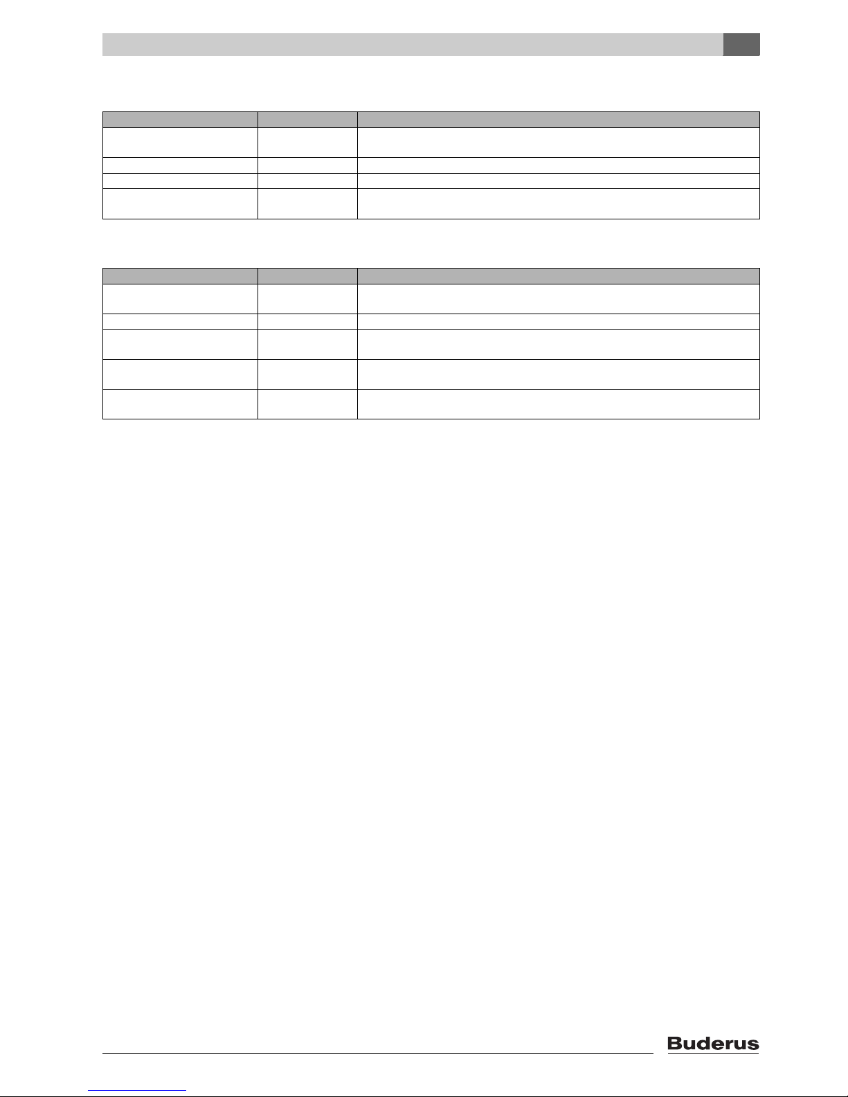
Operating conditions
Boiler output (in case of
multi-boiler systems = total output)
Ventilation air cross-section in square inches
(unrestricted aperture)
Air intake flow cross-section for
combustion air drawn from outside (divided between max. 2
apertures)
< 170,000 Btu/hr At least 23.25 square inches
Tab. 6 Observe national regulations for boilers which draw their air supply from the boiler room.
Operating conditions Notes – Requirement in greater detail
Permissible fuels for boilers without integral burners
− This boiler can be operated with #2 Fuel Oil ASTM D396-05 Type 2. Select a burner that
is suitable for this fuel typ.
Contamination − Free of contaminants (for example dust, mist, humidity), i. e. a constant operation will not
lead to accumulation of deposits, in valves, strainers and filters and could lead to service
calls.
Tab. 7 Fuels
2
Product description
Logano G115 WS US/CA - Technical specifications are subject to change without prior notice.
11
2.8.5 Conditions power supply
2.8.6 Conditions for hydraulic system and water quality
Operating conditions Notes – Requirement in greater detail
Power supply voltage 120 V
AC nominal
Observe the voltage range of the burner and controls used. The outer casing/boiler must
be grounded for safety reasons and in order to function correctly.
Circuit breaker 10 A
Frequency 60 Hz
Enclosure rating − IP 40 (protected against contact by entry of foreign objects > 0.04 inches Ø
(> 1 mm Ø ), no water proofing)
Tab. 8 Power supply
Operating conditions Notes – Requirement in greater detail
Operating pressure (above
atmospheric)
15–58psi Maximum 30 psi with the supplied safety valve.
Permissible site test pressure 45 – 75 psi
Safety temperature limitation by
TR temperature control
122–194°F
Safety temperature limitation by
manual reset high limit (STB)
212 – 248 °F On some controls adjustable on site from 212 to 248 °F.
Water quality − The heating system may only be filled and topped up with water of domestic water quality.
We recommend a pH value of 8.2 – 9.5.
Tab. 9 System configuration and water quality
3
Moving the boiler
Logano G115 WS US/CA - Technical specifications are subject to change without prior notice.
12
3 Moving the boiler
This chapter details how to move the boiler safely.
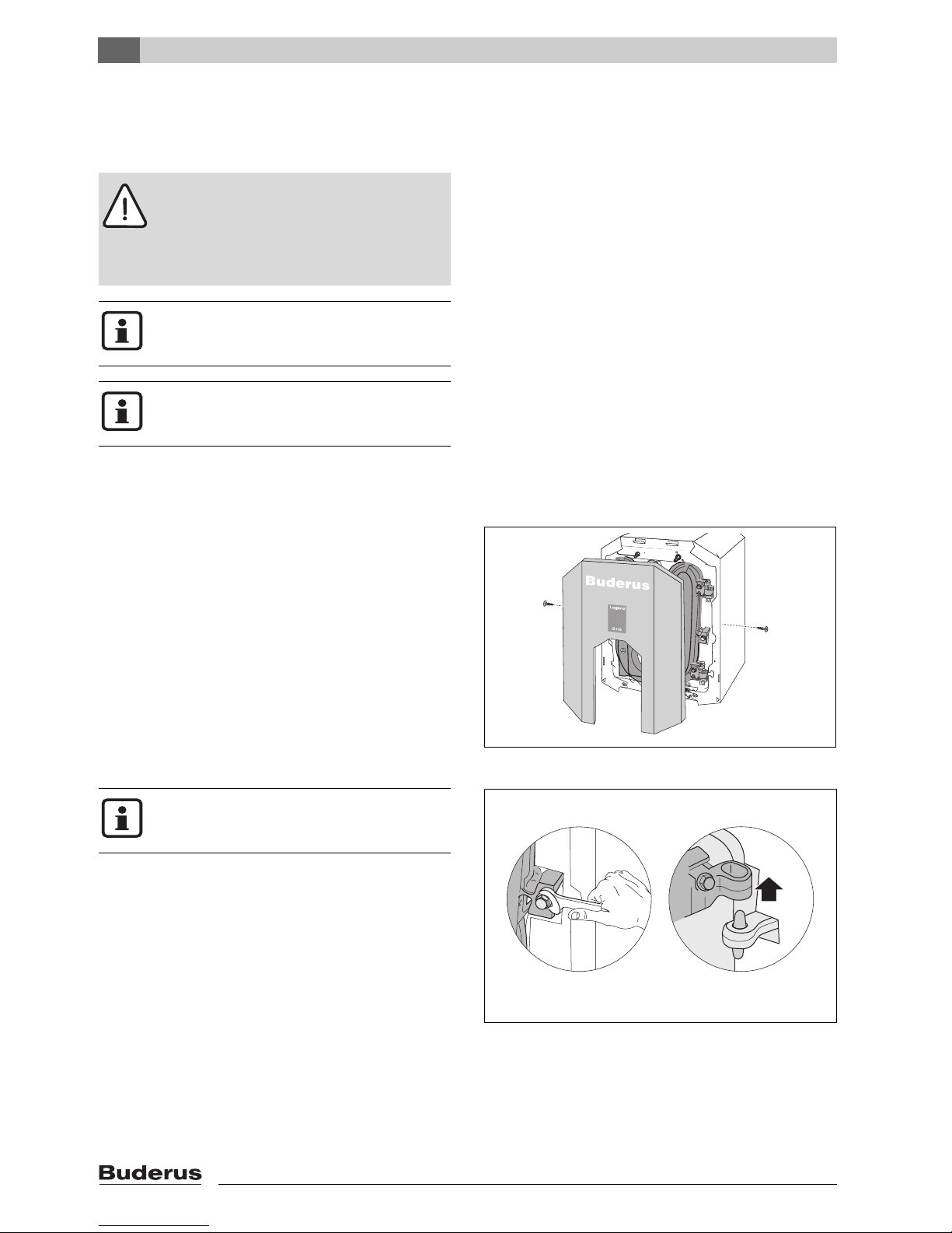
3.1 Reducing boiler weight for transportation purposes
If required, you can reduce the weight of the boiler by
removing the burner hood and door.
V Unscrew the burner door-panel screws.
V Lift burner door panel slightly and draw forward to
remove.
Fig. 3 Removing burner door panel
V Unscrew two hex-head bolts at the sides.
V Open burner door.
V Lift the burner door off its hinges.
Fig. 4 Removing the burner door
Caution: Risk of system damage from impact.
Fragile components could be damaged.
V Observe the transport instructions on the
packaging.
Protect boiler connections from damage and
dirt if the boiler is not installed immediately.
Dispose of packaging in an environmentally
responsible manner.
6 720 615 225-02.1RS
Prevent the burner door from falling over and
damaging the burner and blast tube.
7 747 019 141-04.1RS
3
Moving the boiler
Logano G115 WS US/CA - Technical specifications are subject to change without prior notice.
13
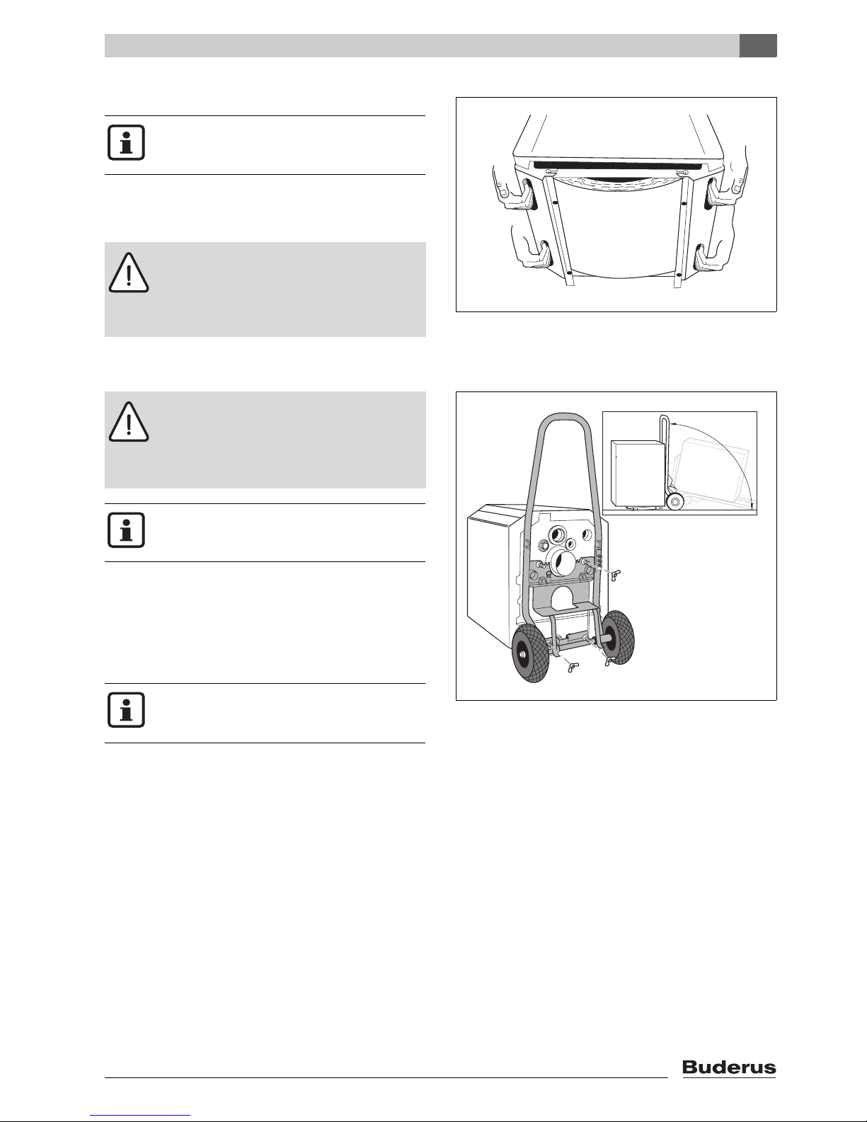
3.2 Lifting and carrying the boiler
The boiler can be held and carried at the grip positions
shown.
V Undo the transit screws.
Fig. 5 Lifting and carrying the boiler
3.3 Using transportation aids to transport the boiler
Moving the boiler with hand truck
V Place the hand truck (e.g. boiler trolley or sack truck) at
the back of the boiler.
V Secure boiler to hand truck using the boiler bolts or
strapping.
V Move the boiler to the installation location.
Fig. 6 Moving the boiler with a boiler hand truck
The boiler is secured to the pallet by 2
screws for transportation purposes.
Caution: Risk of injury from carrying heavy
loads.
V Always lift and move the equipment with
the assistance of another person using the
handle positions shown.
7 747 019 141-05.1RS
Caution: Risk of injury if load is inadequately
secured during transportation.
V Use suitable means of transportation, e.g.
the Buderus boiler hand truck with strap.
V Secure the load against falling.
You can order the boiler hand truck from your
Buderus distributor.
The boiler trolley can also be used to facilitate
work underneath the boiler, e.g. fitting the adjustable feet (Æ Chapter 4.3, page 16).
7 747 019 141-06.1RS
4
Installing the boiler
Logano G115 WS US/CA - Technical specifications are subject to change without prior notice.
14
4 Installing the boiler
This chapter describes how to install and place the boiler
in the boiler room.
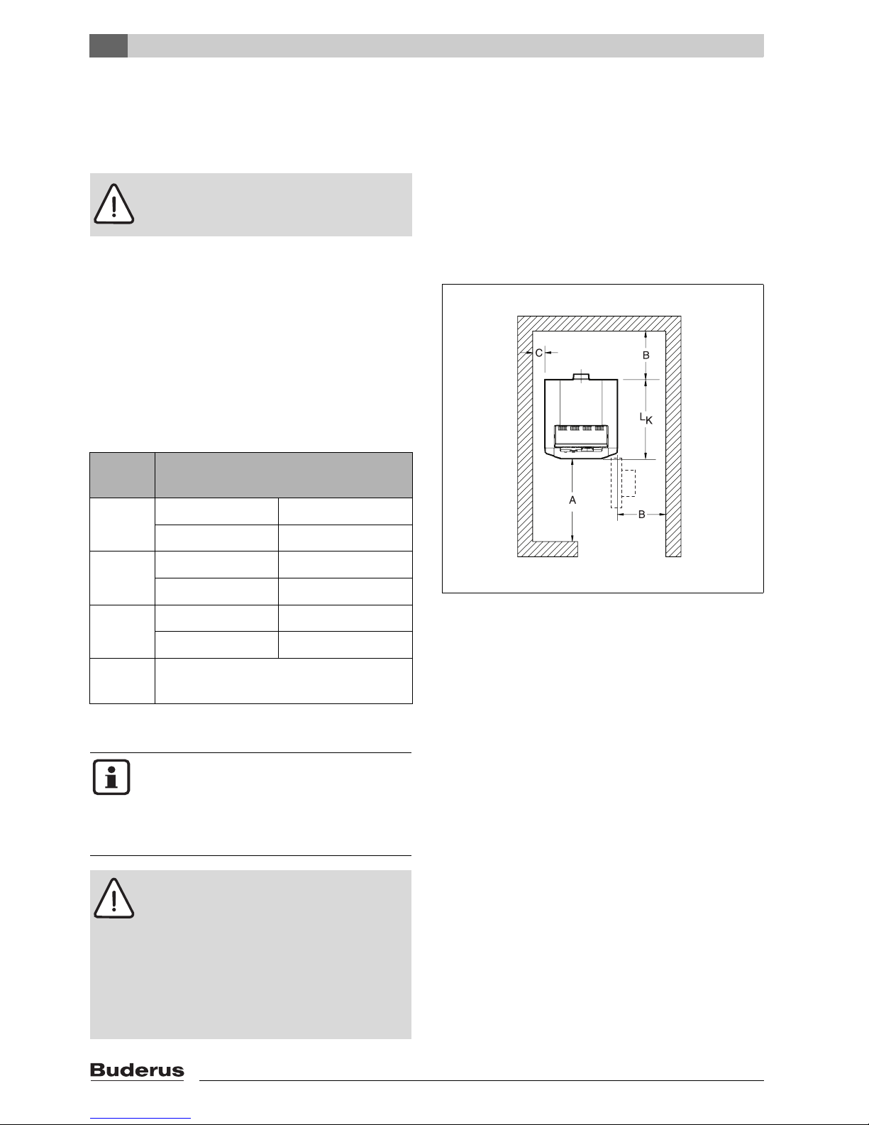
4.1 Wall clearances
Position the boiler with the recommended wall clearances. Reducing the minimum clearances makes the
boiler more difficult to access during installation, maintenance and cleaning.
The boiler base or foundation must be perfectly flat and
level.
The burner door is factory-fitted with the hinges on the
right. The burner door can be converted to open to the left
(Chapter 4.2, page 15).
Fig. 7 Boiler room clearances (boiler positioned on the
l.h. or r.h. side)
Caution:
Risk of system damage from freezing.
V Install the heating system in a frost-free
room.
Dimension
Wall clearance
A Recommended 51-1/8"
minimum 39-3/8"
B Recommended 27-½"
minimum 15-¾"
C Recommended 15-¾"
minimum 3-7/8"
L
K
Æ Chapter 2.7.1 "Logano G115 WS
dimensions", page 8
Tab. 10 Recommended and minimum wall clearances
(dimensions in inches).
7 747 019 141-07.1RS
The boilers are designed for a side clearance
of 6".
Where applicable, allow extra wall clearances for additional components such as DHW
tank, pipe connections, flue gas silencer or
other flue components, etc.
Caution: Risk of fire from flammable materials or liquids.
V Clearances less than 6" must comply with
local and statutory codes.
V Make sure that there is a sufficient clear-
ance between combustible materials and
the chimney connection as specified by
NFPA 31 (distance of 18 ").
V The floor must comply with the require-
ments of NFPA 31.
4
Installing the boiler
Logano G115 WS US/CA - Technical specifications are subject to change without prior notice.
15
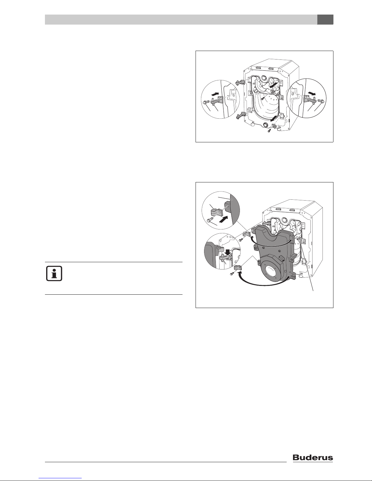
4.2 Reversing boiler door
The burner door is factory-fitted with the hinges on the
right – the burner door opens to the right.You can change
the burner door hinges over to the left-hand side if desired
to suit the installation site.
Remove the burner hood/burner door panel first
(Æ Chapter 3.1, page 12).
V Removing the burner door (Æ Chapter 3.1, page 12).
V Unscrew the hinge bolts and remove the hinges.
V Mount the hinges on the left-hand side of the boiler
using the hinge bolts.
Fig. 8 Reversing the burner door (boiler heat
exchanger attachments)
1 Hinge bolts
2 Hinges
V First remove the hinge lobe bolts and then the hinge
lobes. Mount the hinge barrels on the left-hand side of
the boiler using the hinge-barrel bolts.
V Hook the burner door with the hinge lobes onto the
hinges.
V Check that the heat exchanger baffles are placed hori-
zontally (Æ Chapter 6.3, page 29).
V Close the burner door and secure with the two hexa-
gon-head bolts.Tighten the hexagon-head bolts evenly
(approx. 90 Lbs/inch) so that the burner door seals
properly.
Fig. 9 Reversing the burner door (door attachments)
1 Hinge-barrel bolts
2 Hinge lobes
3 Burner door
4 Hinges
5 Heat exchanger baffle plates
7 747 019 141-08.1RS
12 21
If the burner door hinges have been changed
over to the left-hand side, the burner cable
must be disconnected from the burner before
opening the burner door.
7 747 019 141-09.1RS
1
4
5
2
3
4
Installing the boiler
Logano G115 WS US/CA - Technical specifications are subject to change without prior notice.
16
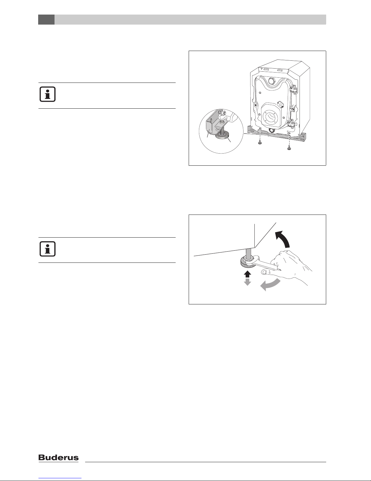
4.3 Mounting the adjustable feet (included with B-kit)
Level the boiler with the adjustable feet to prevent air
pockets forming inside the boiler.
Requirement: the burner hood/burner door panel must
have been removed first (Æ Chapter 3.1, page 12).
V Tilt the boiler with the aid of a hand truck or trolley
(Æ Chapter 3.3, page 13) or place a wooden batten
underneath it.
V Screw in adjustable feet ¼" – 3/8".
V Gently set the boiler down.
Fig. 10 Fitting adjustable feet
1 Angle bracket
2 Adjustable feet
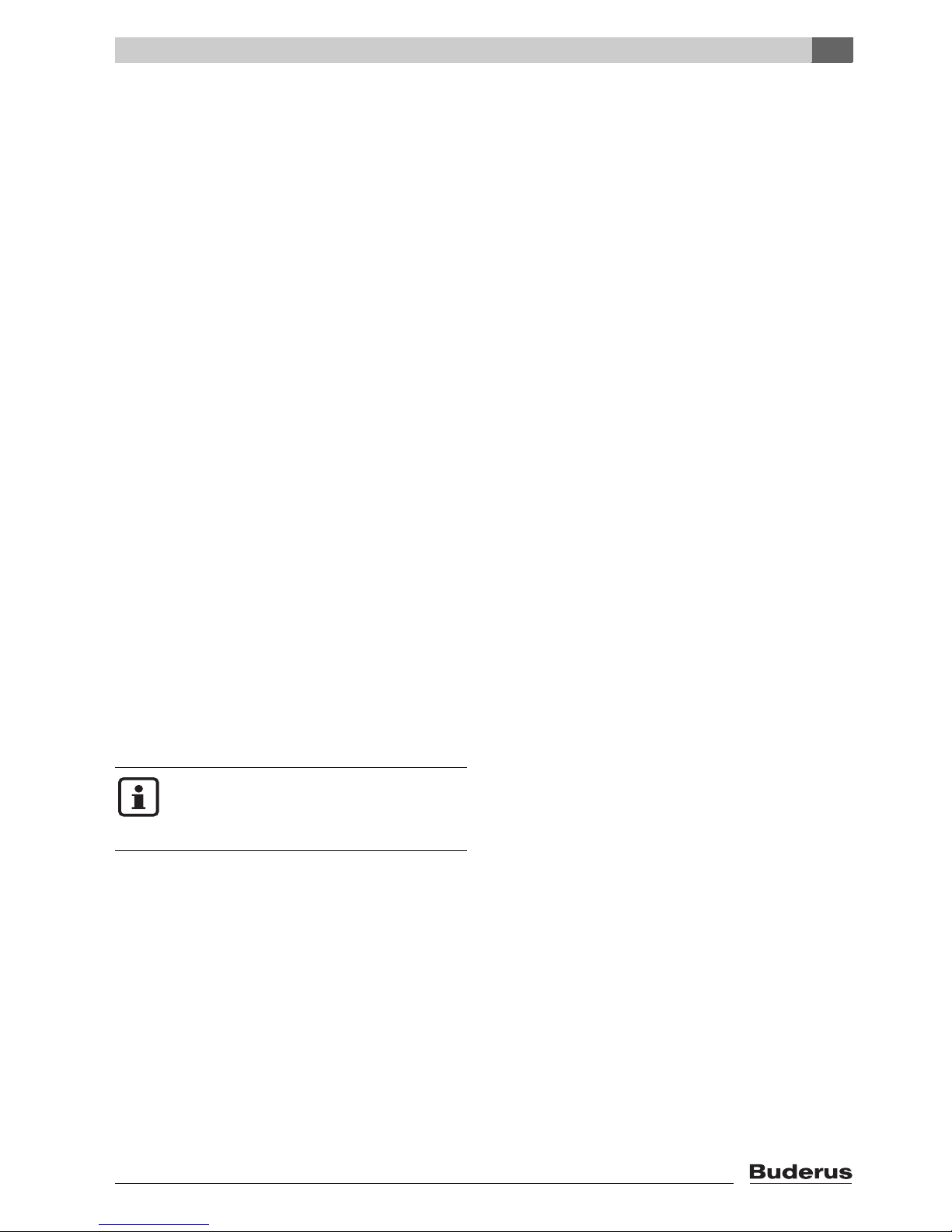
4.4 Positioning and leveling the boiler
V Position the boiler in its final location.
V Level the boiler horizontally by turning the adjustable
feet and using a level.
Fig. 11 Leveling the boiler horizontally
If the boiler is mounted on top of a horizontal
hot water tank, the adjustable feet are not
needed.
7 747 019 141-10.1RS
1
2
Protect boiler connections from damage and
dirt if the boiler is not installed immediately.
7 747 019 141-11.1RS
5
Installing the boiler
Logano G115 WS US/CA - Technical specifications are subject to change without prior notice.
17
5 Installing the boiler
This chapter details how to install your boiler correctly.
The individual steps involved are:
– Connecting the flue
– Connecting the water pipes
– Making the electrical connections
– Fitting the burner
– Connecting the fuel supply
5.1 Flue pipe installation
5.1.1 Chimney venting
Connect boiler to vertical chimney with a 5" vent pipe.
Use only venting systems that comply with local codes
and regulations.
If local codes are not existent, refer the the following regulations:
– NFPA 31, Installation of Oil-Burning Equipment,
– NFPA 211, Standard for Chimneys, Fire Places and
Solid Fuel Burning Appliances,
– In Canada refer to CSA B139, Installation Code for Oil-
Burning Equipment,
– NFPA 211 requires chimney to be lined before con-
necting boiler.
Inspecting and cleaning existing flue
Before installing the new boiler, check and clean the old
flue system.
V Remove blockages and dirt from the chimney.
V Clean chimney.
V Repair or replace faulty sections.
V If necessary, repair chimney with mortar and joints.
Down drafts
To prevent down drafts extend chimney at
least 3 feet above the roof opening and at
least 2 feet above any part of the roof within
a radius of 10 feet.
 Loading...