

Page 1
Service Instructions
Warning: If the information in these instructions is not followed
exactly, a fire or explosion may result causing property damage,
personal injury or loss of life.
WARNING!
Improper installation, adjustment, alteration, service or maintenance can cause
injury, loss of life or property damage. Refer to this manual. For assistance or additional information consult a qualified installer, service agency or the gas supplier.
NOTICE!
In the Commonwealth of Massachusetts this boiler must be installed by a licensed
Plumber or Gas Fitter.
– Do not store or use gasoline or other flammable vapors and liquids in the
vicinity of this or any other appliance.
– What to do if you smell gas
• Do not try to light any boiler.
• Do not touch any electrical switch; do not use any phone in your
building.
• Immediately call your gas supplier from a neighbor’s phone. Follow the
gas supplier’s instructions.
• If you cannot reach your gas supplier, call the fire department.
– Installation and service must be performed by a qualified installer,
service agency or the gas supplier.
Condensing gas boiler
6 720 614 965 (11/2012) US/CA
Notice:
• This manual is available in the English and French language.
• This manual must be retained for future reference.
Logamax plus
GB162-80 kW/100 kW
For the contractor
Please read these
instructions carefully
before servicing!
Page 2
Product Description
10
17
7
1
32
31
20
27
15
29
5
34 2
8
26
25
9
11
12
13
15
14
22
21
18
19
24
23
28
6
33
3637
3538
16
30
39
42
40
41
34
43
Product Description
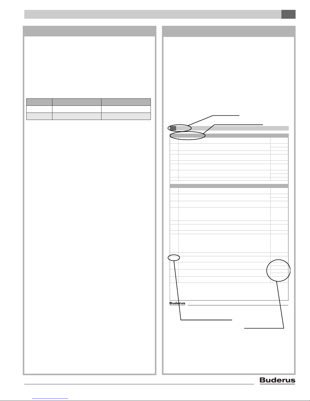
section 1 Product description
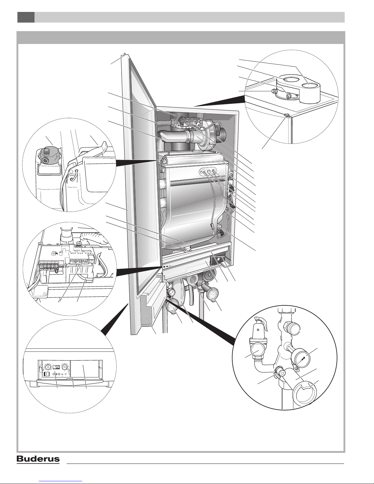
Fig. 1 Logamax plus GB162 with pump group
2
Logamax plus GB162-80 kW/100 kW - Subject to modifications resulting from technical improvements!
Page 3
Product Description
section 2 Legend
1: BC10 basic controller receptacle
2: Installation option for room controller, e.g. RC35
3: Cover with user manual compartment
4: BC10 basic controller, can be expanded e.g. by the RC35
room controller
5: Connection box (low-voltage and 120 VAC connections)
6: Fan harness and mains lead of the pump
7: Condensate drain outlet
8: Condensate collector
9: Boiler front door
10: Automatic air vent
11: Retaining clips
12: Air intake for the fan
13: Gas pipe
14: Flue gas pipe
15: Door lock
16: Flue measuring point
17: Measuring point for air intake
18: Flue gas connection
19: Air intake connection
20: Fan
21: Gas valve
22: Venturi
23: Burner cover
24: Flow temperature sensor
25: Ionization electrode
26: Sight glass
27: Glow ignitor
28: Safety temperature sensor
29: Heat exchanger
30: Pressure sensor
31: Return temperature sensor
32: Universal Burner Automatic Version 3 (UBA 3)
33: Drawer with function module integration options
34: Cover shield
35: Condensate trap
Pump group (scope of delivery):
36: Isolating valve, blue (CH boiler return) with pump, drain
valve, check valve and thermometer
37: Manual gas shutoff valve, yellow (GAS)
38: Isolating valve, red (CH boiler supply) with drain valve,
pressure gauge, thermometer and pressure relief valve
39: Pressure gauge
40: Isolating valve
41: Thermometer (optional accessory)
42: Drain valve
43: Pressure relief valve 30 PSI (2 bar)
(or 50 PSI [3.45 bar] = optional)
The pump group also includes an insulation cover (see also
pump group installation instructions).
Low loss header (scope of delivery, single appliance only)
44: Low loss header (not illustrated)
Logamax plus GB162-80 kW/100 kW - Subject to modifications resulting from technical improvements!
3
Page 4
Contents
section 3 Contents
Section page
Product description . . . . . . . . . . . . . . . . . . . . . . . . . . . . . . . . . . . . . . 2
1 General . . . . . . . . . . . . . . . . . . . . . . . . . . . . . . . . . . . . . . . . . . . . 5
General information . . . . . . . . . . . . . . . . . . . . . . . . . . . . . . . . . . . . . . 5
Layout of this document . . . . . . . . . . . . . . . . . . . . . . . . . . . . . . . . . . 5
Remedying faults using this document . . . . . . . . . . . . . . . . . . . . . . . 6
Logamax plus GB162 . . . . . . . . . . . . . . . . . . . . . . . . . . . . . . . . . . . . 6
2 Safety and general instructions . . . . . . . . . . . . . . . . . . . . . . . . 7
Safety and general instructions . . . . . . . . . . . . . . . . . . . . . . . . . . . . . 7
3 Regulations and guidelines . . . . . . . . . . . . . . . . . . . . . . . . . . . 9
General regulations . . . . . . . . . . . . . . . . . . . . . . . . . . . . . . . . . . . . . . 9
Regulations in Massachusetts . . . . . . . . . . . . . . . . . . . . . . . . . . . . . 9
4 Operation . . . . . . . . . . . . . . . . . . . . . . . . . . . . . . . . . . . . . . . . . 10
General . . . . . . . . . . . . . . . . . . . . . . . . . . . . . . . . . . . . . . . . . . . . . . 10
Menu structure . . . . . . . . . . . . . . . . . . . . . . . . . . . . . . . . . . . . . . . . 12
Normal Operation menu . . . . . . . . . . . . . . . . . . . . . . . . . . . . . . . . . 13
Flue Gas Test menu . . . . . . . . . . . . . . . . . . . . . . . . . . . . . . . . . . . . 13
Service Mode menu . . . . . . . . . . . . . . . . . . . . . . . . . . . . . . . . . . . . 14
Manual Operation menu . . . . . . . . . . . . . . . . . . . . . . . . . . . . . . . . . 15
Settings menu . . . . . . . . . . . . . . . . . . . . . . . . . . . . . . . . . . . . . . . . . 15
Operation . . . . . . . . . . . . . . . . . . . . . . . . . . . . . . . . . . . . . . . . . . . . 17
5 Symptoms . . . . . . . . . . . . . . . . . . . . . . . . . . . . . . . . . . . . . . . . 21
Symptoms . . . . . . . . . . . . . . . . . . . . . . . . . . . . . . . . . . . . . . . . . . . . 21
Removing the control panel . . . . . . . . . . . . . . . . . . . . . . . . . . . . . . 21
Display readings . . . . . . . . . . . . . . . . . . . . . . . . . . . . . . . . . . . . . . . 21
Display settings . . . . . . . . . . . . . . . . . . . . . . . . . . . . . . . . . . . . . . . . 21
Display codes and other symptoms . . . . . . . . . . . . . . . . . . . . . . . . 21
6 Diagnosis . . . . . . . . . . . . . . . . . . . . . . . . . . . . . . . . . . . . . . . . . 30
Diagnosis . . . . . . . . . . . . . . . . . . . . . . . . . . . . . . . . . . . . . . . . . . . . 30
7 Actions . . . . . . . . . . . . . . . . . . . . . . . . . . . . . . . . . . . . . . . . . . . 56
Hanging the control panel from the boiler . . . . . . . . . . . . . . . . . . . . 56
Shutting down . . . . . . . . . . . . . . . . . . . . . . . . . . . . . . . . . . . . . . . . . 56
Switching off main power . . . . . . . . . . . . . . . . . . . . . . . . . . . . . . . . 56
Closing cover of the BC10 . . . . . . . . . . . . . . . . . . . . . . . . . . . . . . . 57
Switching off power supply . . . . . . . . . . . . . . . . . . . . . . . . . . . . . . . 57
Opening boiler door . . . . . . . . . . . . . . . . . . . . . . . . . . . . . . . . . . . . . 57
Closing isolating valves . . . . . . . . . . . . . . . . . . . . . . . . . . . . . . . . . . 57
Draining the system . . . . . . . . . . . . . . . . . . . . . . . . . . . . . . . . . . . . 57
Opening isolating valves . . . . . . . . . . . . . . . . . . . . . . . . . . . . . . . . . 58
Closing boiler door . . . . . . . . . . . . . . . . . . . . . . . . . . . . . . . . . . . . . 58
Filling and bleeding the system . . . . . . . . . . . . . . . . . . . . . . . . . . . . 58
Switch on power supply . . . . . . . . . . . . . . . . . . . . . . . . . . . . . . . . . 59
Switching on main power . . . . . . . . . . . . . . . . . . . . . . . . . . . . . . . . 59
Initial startup . . . . . . . . . . . . . . . . . . . . . . . . . . . . . . . . . . . . . . . . . . 60
Checking/replacing fuses . . . . . . . . . . . . . . . . . . . . . . . . . . . . . . . . 61
Checking the fan unit; operation (120 VAC) . . . . . . . . . . . . . . . . . . 61
Checking the fan unit; power supply cord (120 VAC) . . . . . . . . . . . 62
Checking the fan unit; tacho cable . . . . . . . . . . . . . . . . . . . . . . . . . 62
Checking and/or replacing the fan unit . . . . . . . . . . . . . . . . . . . . . . 63
Checking the pump; mechanical obstruction . . . . . . . . . . . . . . . . . 64
Checking the pump; activation . . . . . . . . . . . . . . . . . . . . . . . . . . . . 65
Checking the pump; power supply cord . . . . . . . . . . . . . . . . . . . . . 65
Checking the pump; tacho cable . . . . . . . . . . . . . . . . . . . . . . . . . . . 66
Checking the pump; pollution . . . . . . . . . . . . . . . . . . . . . . . . . . . . . 67
Replacing the pump . . . . . . . . . . . . . . . . . . . . . . . . . . . . . . . . . . . . 67
Checking the supply, safety, return and DHW temperature sensors 68
Checking the supply, safety, return and DHW temperature
sensors; cables . . . . . . . . . . . . . . . . . . . . . . . . . . . . . . . . . . . . . 69
Replacing the feed, safety and return sensors . . . . . . . . . . . . . . . . 71
Replacing the DHW temperature sensor . . . . . . . . . . . . . . . . . . . . 72
Section page
Checking the flue gas sensor . . . . . . . . . . . . . . . . . . . . . . . . . . . . . 72
Checking the flue gas sensor; cable . . . . . . . . . . . . . . . . . . . . . . . . 73
Replacing the flue gas sensor . . . . . . . . . . . . . . . . . . . . . . . . . . . . . 74
Checking the glow ignitor; activation . . . . . . . . . . . . . . . . . . . . . . . . 74
Checking the glow ignitor; resistance . . . . . . . . . . . . . . . . . . . . . . . 75
Checking the glow ignitor; power supply cord . . . . . . . . . . . . . . . . . 75
Replacing the ignition unit . . . . . . . . . . . . . . . . . . . . . . . . . . . . . . . . 76
Measure the ionization current . . . . . . . . . . . . . . . . . . . . . . . . . . . . 76
Checking the ionization electrode; short circuit . . . . . . . . . . . . . . . . 77
Checking the ionization electrode; cable . . . . . . . . . . . . . . . . . . . . . 78
Checking the ionization electrode . . . . . . . . . . . . . . . . . . . . . . . . . . 78
Checking the ionization circuit; ground lead . . . . . . . . . . . . . . . . . . 79
Checking the gas valve; power supply plug . . . . . . . . . . . . . . . . . . 79
Checking the gas valve; activation . . . . . . . . . . . . . . . . . . . . . . . . . 79
Checking the gas valve; electrical resistance of the power
supply cord . . . . . . . . . . . . . . . . . . . . . . . . . . . . . . . . . . . . . . . . . 80
Checking the gas valve; internal electrical resistance . . . . . . . . . . . 80
Replacing the gas valve . . . . . . . . . . . . . . . . . . . . . . . . . . . . . . . . . 81
Checking the ON/OFF controller . . . . . . . . . . . . . . . . . . . . . . . . . . . 82
Checking the RC regulator . . . . . . . . . . . . . . . . . . . . . . . . . . . . . . . 82
Checking an external switch contact . . . . . . . . . . . . . . . . . . . . . . . . 83
Measuring the difference between the static and dynamic
gas supply pressures . . . . . . . . . . . . . . . . . . . . . . . . . . . . . . . . . 83
Bleeding the gas supply pipe . . . . . . . . . . . . . . . . . . . . . . . . . . . . . . 84
Measuring and adjusting the gas/air ratio . . . . . . . . . . . . . . . . . . . . 84
Checking the transformer; internal electrical resistance . . . . . . . . . 85
Checking the transformer; power supply cord and low-voltage cord 86
Replace transformer . . . . . . . . . . . . . . . . . . . . . . . . . . . . . . . . . . . . 86
Checking the wire harness; connections . . . . . . . . . . . . . . . . . . . . . 87
Checking the cotrol panel; supply voltage . . . . . . . . . . . . . . . . . . . . 87
Replacing the automatic air purging system . . . . . . . . . . . . . . . . . . 88
Replacing/cleaning the burner . . . . . . . . . . . . . . . . . . . . . . . . . . . . . 88
Replacing/cleaning the siphon . . . . . . . . . . . . . . . . . . . . . . . . . . . . . 89
Checking/replacing the pressure sensor; pollution . . . . . . . . . . . . . 89
Replacing/cleaning the heat exchanger . . . . . . . . . . . . . . . . . . . . . 89
Replacing the UBA 3 . . . . . . . . . . . . . . . . . . . . . . . . . . . . . . . . . . . . 91
8 Appendix. . . . . . . . . . . . . . . . . . . . . . . . . . . . . . . . . . . . . . . . . . 92
Electrical wiring diagram . . . . . . . . . . . . . . . . . . . . . . . . . . . . . . . . . 92
Legend of electrical wiring diagram . . . . . . . . . . . . . . . . . . . . . . . . . 93
Power rating . . . . . . . . . . . . . . . . . . . . . . . . . . . . . . . . . . . . . . . . . . 93
Sensor resistance readings . . . . . . . . . . . . . . . . . . . . . . . . . . . . . . . 93
Technical Specifications of GB162-boilers at sea level (0-4,000 ft) 94
Spare parts list . . . . . . . . . . . . . . . . . . . . . . . . . . . . . . . . . . . . . . . . . 96
Spare parts list (continued) . . . . . . . . . . . . . . . . . . . . . . . . . . . . . . . 96
Exploded view Logamax plus GB162-80 kW/100 kW . . . . . . . . . . . 97
Exploded view pump group Logamax plus GB162-80 kW/100 kW . 98
4
Logamax plus GB162-80 kW/100 kW - Subject to modifications resulting from technical improvements!
Page 5
1 General
Operation4
Logamax plus GB162-80 kW/100 kW - Subject to modifications resulting from technical improvements!
14
section 22 Normal Operation menu
Step 1
./D
Display reading: Currently measured heating system flow temperature in °C.
See also section 30 "Display readings", page 22.
Step 2 Continue in Normal Operation menu? Yes:
o
Step 3
No:
o
Step 1
Step 3 zPress the "
e
" button.
Step 4
.?D
Display reading: Currently measured heating system water pressure in bar.
See also section 30 "Display readings", page 22.
Step 5 zPress the "
e
" button.
Step 6
.:/D
Random operating code. In this case: Operating code: The boiler is in heating mode.
See also section 32 "Display codes and other symptoms", page 22, and further.
Step 7 Have at least 5 seconds passed without a button being pressed and/or has the mains voltage been interrupted ? Yes:
o
Step 1
No:
o
Step 8
Step 8 zPress the "
e
" button.
o
Step 1
section 23 Flue Gas Test menu
Step 1
./D
Display reading: Currently measured heating system flow temperature in °C.
See also section 30 "Display readings", page 22.
Step 2 Activate flue gas test? Yes:
o
Step 3
No:
o
Step 1
Step 3 To activate the flue gas test:
zPress and hold the "
d
" button for more than 2 but not longer than 5 seconds.
Step 4
./0
Display reading: Current heating system flow temperature in °C.
As soon as a non
-
flashing dot is shown in the bottom right-hand corner of the display, the flue gas test has been
activated. This means that the boiler is in heating mode at a capacity of 100 % for a maximum period of 30 minutes.
The maximum heating system flow temperature set on the BC10 basic controller now applies. DHW mode is not
possible during the flue gas test.
Step 5 zPress the "
e
" button.
Step 6
.?0
Display reading: Currently measured heating system water pressure in bar.
See also section 30 "Display readings", page 22.
Step 7 zPress the "
e
" button.
Step 8
.4/0
Operating code: A flue gas test is being carried out or the boiler is in service m ode.
Flue gas test: The boiler is in heating mode at a capacity of 100 % for a maximum of 30 minutes.
The maximum heating system flow temperature set on the BC10 basic controller now applies.
Service mode: The boiler is in heating mode at a reduced capacity for a period of 30 minutes.
The maximum heating system flow temperature set on the BC10 basic controller now applies.
DHW mode is not possible during the flue gas test or during service mode.
See also section 32 "Display codes and other symptoms", page 22, and further.
Step 9 Press the "
e
" button.
Step 10
./0
Display reading: Currently measured heating system flow temperature in °C.
See also section 30 "Display readings", page 22.
Step 11 Have 30 minutes passed or has the mains voltage been interrupted? Yes:
o
Step 1
No:
o
Step 12
Step 12 Deactivate flue gas test? Yes:
o
Step 13
No:
o
Step 5
Step 13 To deactivate the flue gas test:
zPress and hold the "
d
" button for more than 2 seconds until the dot disappears.
o
Step 1
Section
Subsection with ID number
Operating step with number
Cross-reference to
subsection or
operating step
section 4 General information
General 1
section 5 Layout of this document
About these instructions
These servicing instructions contain important information for
the safe and professional servicing of the boiler with boiler input
rating of 80 kW and 100 kW.
The name of the boiler is made up of the following components:
– Logamax plus: heating boiler typical
– GB162: single boiler without domestic hot water supply
– 80 kW/100 kW: maximum heating capacity is 80 or 100 kW.
GB162 Natural Gas Propane Gas
80 kW 290,000 btu/hr 270,000 btu/hr
100 kW 333,000 btu/hr 315,000 btu/hr
Table 1 max. input rate
These servicing instructions are intended for professional
installers, who have the necessary training and experience for
working on heating and gas systems.
Cascade installation
Special cascade units (accessories) have been developed to
enable this boiler to be installed in a cascade system. Every
cascade unit includes an installation frame, horizontal headers,
connection pipes for the boiler, main gas pipe and a vertical low
loss header.
Cascade units are available for installing the boilers inline or
back-to-back. These cascade units make installing a cascade
system easier and less labor intensive.
Please contact Buderus for further information about cascade
systems.
Updating of documentation
The following technical documentation is available for the
Logamax plus GB162-80 kW/100 kW:
– Installation Instructions
– User’s Manual
– Service Instructions.
Please contact us if you have any suggestions for improvement
or corrections.
Subject to technical modifications
Slight changes may be made without prior notice to the illustra-
tions, process steps and technical data as a result of our policy
of continuous improvement.
This document consists of various sections. They have been
divided into subsections.
Every subsection is marked with a grey frame. An ID number is
always provided in the top left-hand corner. References in the
document are based on these ID numbers.
In addition, a subsection may be divided into various numbered
operating steps. Reference to a certain operating step is
always made within the same subsection. If an operating step
involves the taking of a yes/no decision, the right-hand side of
the table indicates which operating step or subsection you
should proceed with (cross-reference).
Logamax plus GB162-80 kW/100 kW - Subject to modifications resulting from technical improvements!
5
Page 6
General1
section 6 Remedying faults using this document
FAULTS CAN BE REMEDIED USING THIS DOCUMENT, BY
FOLLOWING A 3-STEP PLAN. IT IS IMPORTANT THAT THE
SAME SEQUENCE IS FOLLOWED EVERY TIME.
Step 1: Symptoms
Step 2: Diagnosis
Step 3: Action
Step 1: chapter 5 Symptoms
Symptom = every indication which may be relevant in order to
recognize faults or errors.
An important symptom is the display indication on the BC10
basic controller of the boiler, but all other symptoms must also
be taken into consideration. In most cases, the display indication (e.g. the locking fault code
from the BC10 basic controller, but the user of the boiler must
also be asked whether other symptoms have occurred. Examples of such symptoms are "the boiler makes whistling noises in
the morning" or "the room does not reach the required temperature". The display indications and their meanings as well as
other symptoms are described in section 29 "Display codes and
other symptoms" on page 21.
There are three types of display indication:
– display reading (section 27 "Display readings" on page 21)
– display setting (section 28 "Display settings" on page 21)
– display code (section 29 "Display codes and other
symptoms" on page 21).
There are three types of display code:
– operating code
This code gives the status of the boiler. No action is
necessary.
– blocking fault code
The boiler is locked and will only restart after a manual reset.
The pump will operate continuously for frost protection.
– locking fault code
The boiler resumes normal operation when the fault has
cleared.
Every display code (e.g. the locking fault code
consists of:
– a main code (in this case [2/l/\|)
– a subcode (in this case
After reading the main code, the subcode can be called up by
pressing the service key.
[2/l/\| [2/6/6|) can easily be read
[2/l/\| [2/6/6|)
[2/6/6|).
Step 3: chapter 7 Actions
Action = remedying the cause of the fault or error.
After laying down the diagnosis, the fault can be remedied by
means of chapter 7 "Actions" on page 56.
section 7 Logamax plus GB162
The Logamax plus GB162 condensing gas boiler is a fully upto-date central heating boiler, designed to provide a high level
of convenience, maximum energy savings, optimum care for
the environment and advanced safety features – all in a single
device.
This is why the boiler is equipped with the very latest electronics. The electronic system consists of the UBA 3 (= Universal
Burner Automat 3) (see section 1, [32]) and the connected control panel, the BC10 (= Basic Controller 10) (see section 1, [4]).
The main task of this electronic system is to control and ensure
the safe operation of the central heating boiler.
In addition, it is possible to call up display readings, settings and
codes on the display of the BC10. The display settings can be
changed after calling them up. Also see section 23 and
section 28.
The working of the boiler during normal operation mode is
explained in more detail in chapter 4 "Operation" on page 10.
This chapter provides a step-by-step explanation of the boiler
operation under normal operating conditions.
Step 2: chapter 6 Diagnosis
Diagnosis = establishing the cause of the fault or error on the
basis of the symptoms.
A diagnosis (chapter 6 "Diagnosis" on page 30) can be made
after determining all symptoms.
The right-hand column of the symptoms overview (section 5
"Symptoms" on page 21) refers to the corresponding diagnosis
box. The diagnosis box can be used next to easily find the
cause of the fault.
6
Logamax plus GB162-80 kW/100 kW - Subject to modifications resulting from technical improvements!
Page 7
2 Safety and general instructions
section 8 Safety and general instructions
Please observe these instructions in the interest of your own
safety.
Designated use
The boiler was designed for heating water for a central heating
system and generating domestic hot water.
The boiler is suitable for connection to fully pumped, sealed
water systems ONLY.
The boiler can be installed either as a single system or as part
of a multiple system (cascade system) with a maximum of 8
boilers connected together.
These boilers may not be installed in places over 4,000 ft. above
sea level.
Hazard definitions
The following defined terms are used throughout the documen-
tation to bring attention to the presence of hazards of various
risk levels. Notices give important information concerning the
operation of the product.
DANGER
Indicates the presence of hazards that will cause
severe personal injury, death or substantial property
damage.
WARNING
Indicates the presence of hazards that can cause
severe personal injury, death or substantial property
damage.
CAUTION
Indicates presence of hazards that will or cause
minor personal injury or property damage.
CAUTION
Risk of electric shock.
Indicates presence of hazards due to electric shock.
NOTICE
Indicates special instructions on installation, operation or maintenance that are important but not
related to personal injury or property damage.
Safety and general instructions 2
The following instructions must be observed
– The boiler must only be used for its designated purpose,
observing the Installation Instructions.
– Only use the boiler in the combinations and with the accesso-
ries and spares listed.
– Maintenance and repairs must only be carried out by trained
professionals.
– You are only permitted to operate the condensing gas boiler
with the combustion air/flue gas system that has been specifically designed and approved for this type of boiler.
– Please note that local approval of the flue system and the
condensate connection to the public sewer system may be
required.
– If boiler installation is provided as replacement heater,
DO NOT connect new boiler venting to an existing vent
system, if it is shared with other appliances.
You must also observe:
– The local building regulations stipulating the installation rules
at the time of installation.
– The local building regulations concerning the air intake and
outlet systems and the chimney connection.
– The regulations for the power supply connection.
– The technical rules laid down by the gas utility company con-
cerning the connection of the gas burner fitting to the local
gas main.
– The instructions and standards concerning the safety equip-
ment for the water/space heating system.
– The Installation Instructions for building heating systems.
– The boiler must be located in an area where leakage of the
tank or connections will not result in damage to the area adjacent to the boiler or to lower floors of the structure. When
such locations cannot be avoided, it is recommended that a
suitable drain pan, adequately drained, be installed under the
boiler. The pan must not restrict combustion air flow.
– The boiler must be installed such that the gas ignition system
components are protected from water (dripping, spraying,
rain etc.) during boiler operation and service.
– The boiler must not be installed on carpeting.
– Do not restrict or seal any air intake or outlet openings.
– If you find any defects, you must inform the owner of the sys-
tem of the defect and the associated hazard in writing.
Logamax plus GB162-80 kW/100 kW - Subject to modifications resulting from technical improvements!
7
Page 8
Safety and general instructions2
DANGER
if flammable gas explodes.
Beware if you smell gas: there may be an explosion
hazard!
Warning: If the information in these instructions
is not followed exactly, a fire or explosion may
result causing property damage, personal injury
or death.
Do not store or use gasoline or other flammable
vapors and liquids in the vicinity of this or any
other boiler.
What to do if you smell gas
Do not try to light any boiler.
Do not touch any electrical switch; do not use
any phone in your building.
Immediately call your gas supplier from
a neighbor’s phone. Follow the gas supplier’s
instructions.
If you cannot reach your gas supplier, call the fire
department.
Installation and service must be performed by a
qualified installer, service agency or the gas supplier.
WARNING
Danger of fatal accident from explosive fumes.
Only carry out work on gas pipes and fittings if
you are properly registered.
WARNING
Dangerous flue gas can escape if the air supply is
insufficient.
Make sure that air vents are not reduced in size
or obstructed.
The boiler may only be operated after the defect
has been remedied.
Warn the user of the system of the defect ver-
bally and in writing.
Heating system requirements
– Installing a dirt trap like a y-strainer and a desludging device
is required. This must be installed in the heating system in the
immediate vicinity of the boiler, in an easily accessible position between the boiler and the lowest point in the return of
the system.
– Clean the dirt trap at every annual service.
– Never use salt bedding type exchangers (ion exchangers) to
soften the water.
– The low loss header and boiler connection set must be
installed (supplied with the boiler).
– When using oxygen-permeable pipes (plastic), e.g. for floor
heating systems, you must separate the system using secondary heat exchangers.
Heating system water quality
The quality of the system water is very important. Poor water
quality can damage heating systems due to scale formation and
corrosion. For further details, please see the accompanying
"Water quality requirements for Logamax plus GB162-80 kW/
100 kW" manual.
CAUTION
Risk of system damage due to unsuitable heating
system water.
If oxygen-permeable pipes are used, e.g. for
underfloor heating systems, the systems must
be separated from one another by plate heat
exchangers. Unsuitable heating system water
promotes sludge and corrosion formation. This
can result in heat exchanger malfunction and
damage.
Pump test
If the boiler has not been operational for approx. 4 weeks, the
pump will automatically run for 10 seconds every 24 hours. This
pump test is first carried out 24 hours after the main power has
been connected to the boiler.
Freeze protection
The boiler has integrated freeze protection that switches the
boiler ON at a space heating (CH) water temperature of 45 °F
(7 °C) and switches it OFF at a CH supply temperature of 59 °F
(15 °C).
This feature does not protect the central heating system from
freezing. If there is a risk of radiators or pipe sections freezing
up, we recommend setting the pump run-over time to 24 hours.
Tools, materials and further equipment
For the installation and maintenance of the boiler you will need
the standard tools for space heating, gas and water fitting.
In addition, a hand truck with a fastening belt is useful.
Disposal
– Dispose of the boiler packaging in an environmentally sound
manner.
– Dispose of components of the heating system (e. g. boiler or
control device), that must be replaced in an environmentally
responsible manner.
8
Logamax plus GB162-80 kW/100 kW - Subject to modifications resulting from technical improvements!
Page 9
3 Regulations and guidelines
section 9 General regulations
The installation must conform to the requirements of the author-
ity having jurisdiction or, in the absence of such requirements,
to the latest edition of the National Fuel Gas Code, ANSI
Z223.1./NFPA 54. In Canada, installation must be in accor-
dance with the requirements of CAN/CSA B149.1, Natural Gas
and Propane Installation Code. Where required by the authority
having jurisdiction, the installation must conform to the Stan-
dard for Controls and Safety Devices for Automatically Fired
Boilers, ANSI/ASME CSD-1. Install CO detectors per local
regulations. Boiler requires yearly maintenance.
Operating Limits of the boiler:
Max. boiler temperature: 230 °F (110 °C)
Max. operating pressure: 30 psi (2.6 bar)
– with optional pressure relief valve 50 psi (3.45 bar).
The hot water distribution system must comply with all applica-
ble codes and regulations. When replacing an existing boiler, it
is important to check the condition of the entire hot water distri-
bution system to ensure safe operation.
section 10 Regulations in Massachusetts
Massachusetts Installations Only:
(a) For all side wall side horizontally vented gas fueled equip-
ment installed in every dwelling, building or structure used in
whole or in part for residential purposes, including those owned
or operated by the Commonwealth and where the side wall
exhaust vent termination is less than seven (7) feet above fin-
ished grade in the area of the venting, including but not limited
to decks and porches, the following requirements shall be
satisfied:
1. INSTALLATION OF CARBON MONOXIDE DETECTORS.
At the time of installation of the side wall horizontal vented
gas fueled equipment, the installing plumber or gasfitter
shall observe that a hard wired carbon monoxide detector
with an alarm and battery back-up is installed on the floor
level where the gas equipment is to be installed. In addition,
the installing plumber or gasfitter shall observe that a battery
operated or hard wired carbon monoxide detector with an
alarm is installed on each additional level of the dwelling,
buiding or structure served by the side wall horizontal
vented gas fueled equipment. It shall be the responsibility of
the property owner to secure the services of qualified
licensed professionals for the installation of hard wired carbon monoxide detectors.
a. In the event that the side wall horizontally vented gas
fueled equipment is installed in a crawl space or an attic,
the hard wired carbon monoxide detector with alarm and
battery back-up may be installed on the next adjacent
floor level.
b. In the event that the requirements of this subdivision can
not be met at the time of completion of installation, the
owner shall have a period of thirty (30) days to comply
with the above requirements; provided, however, that
during said thirty (30) day period, a battery operated carbon monoxide detector with an alarm shall be installed.
Regulations and guidelines 3
2. APPROVED CARBON MONOXIDE DETECTORS.
Each carbon monoxide detector as required in accordance
with the above provisions shall comply with NPA 720 and be
ANSI/UL 2034 listed and IAS certified.
3. SIGNAGE. A metal or plastic identification plate shall be
permanently mounted to the exterior of the building at a minimum height of eight (8) feet above grade directly in line with
the exhaust vent terminal for the horizontally vented gas
fueled heating appliance or equipment. The sign shall read,
in print size no less than one-half (½) inch in size, “GAS
VENT DIRECTLY BELOW. KEEP CLEAR OF ALL
OBSTRUCTIONS”.
4. INSPECTION. The state or local gas inspector of the side
wall horizontally vented gas fueled equipment shall not
approve the installation unless, upon inspections, the
inspector observes carbon monoxide detectors and signage
installed in accordance with the provisions of
248 CRM 5.08(2)(a)1 through 4.
(b) EXEMPTIONS: The following equipment is exempt from
248 CRM 5.08(2)(a)1 through 4:
1. The equipment listed in Chapter 10 entitled “Equipment
Not Required To Be Vented” in the most current edition
of NFPA 54 as adopted by the board: and
2. Product Approved side wall horizontally vented gas
fueled equipment installed in a room or structure separate from the dwelling, building or structure used in whole
or in part for residential puposes.
(c) MANUFACTURERS REQUIREMENTS - GAS EQUIPMENT VENTING SYSTEM REQUIRED.
When the manufacturer of Product Approved side wall horizontally mounted gas equipment provides a venting system design
or venting system components with the equipment, the instructions provided by the manufacturer for the installation of the
equipment and venting shall include:
1. Detailed instructions for the installation of the venting
system or the venting system components: and
2. A complete parts list for the venting system design or
venting system.
(d) MANUFACTURERS REQUIREMENTS - GAS EQUIPMENT VENTING SYSTEM NOT PROVIDED.
When the manufacturer of Product Approved side wall horizontally vented gas fueled equipment does not provide the parts for
the venting of flue gases, but identifies “special venting systems”, the following requirements shall be satisfied by the manufacturer:
1. The referenced “special venting systems” shall be
included with the appliance or equipment installation
instructions: and
2. The “special venting systems” shall be Product Approved
by the Board, and the instructions for that system shall
include a parts list and detailed installation instructions.
(e) A copy of all instructions for all Product Approved side wall
horizontally vented gas fueled equipment, all venting instructions, all parts lists for venting instructions, and/or venting
design instructions shall remain with the appliance or equipment at the completion of the installation.
Logamax plus GB162-80 kW/100 kW - Subject to modifications resulting from technical improvements!
9
Page 10
Operation4
1
1
23 4
7
8910
26
11
5
140
130
120
90
100
130
170
150
90
190
110
110
4Operation
section 11 General
section 14
General points
The heating boiler is fitted with a control panel, the BC10 basic
controller. The BC10 can be used to control the heating system.
In addition, it is possible to call up display readings, settings and
codes on the display of the BC10. The display settings can be
changed after calling them up. See chapter 5 "Symptoms" on
page 21.
section 12
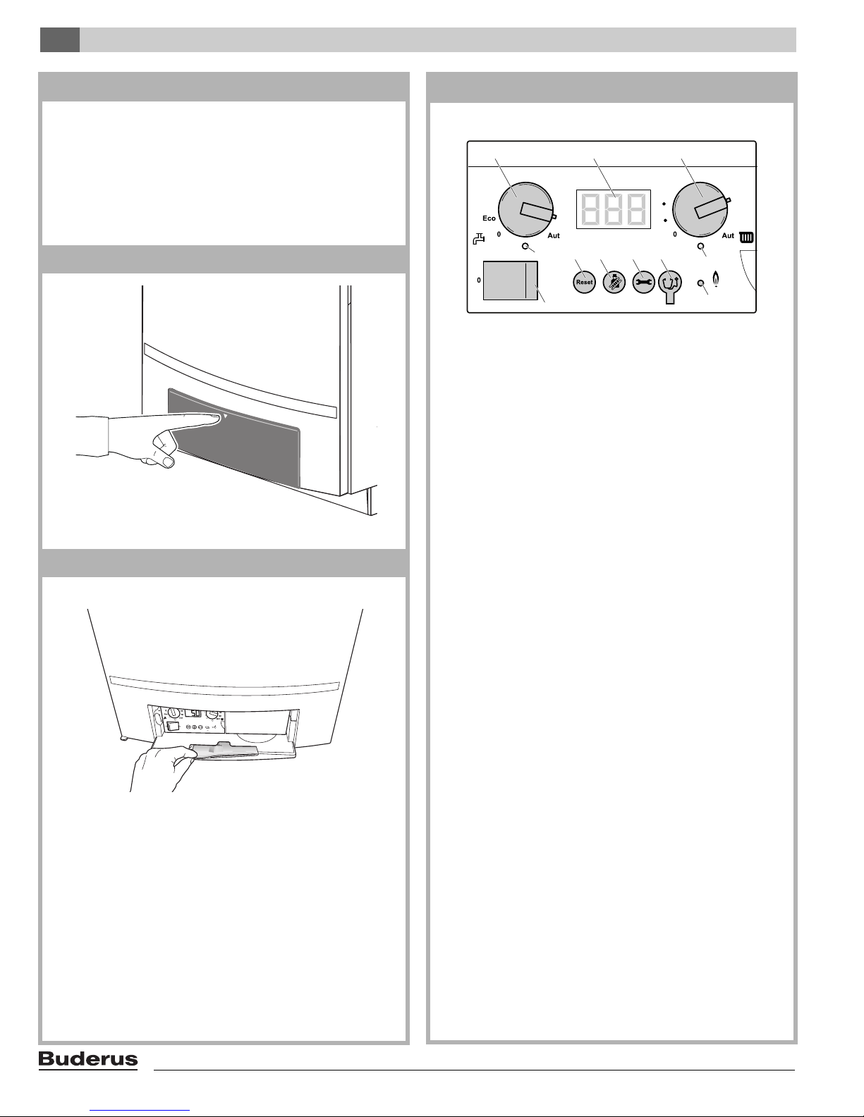
The control panel has the following elements:
1: Main power switch
2: "Reset" button
3: "Chimney sweep" button
4: "Service" button
5: Service Tool Connector
6: LED "Burner operation"
7: LED "Central heat demand"
8: Space heating water temperature knob
9: Display
10: DHW temperature knob
11: LED "DHW demand"
Briefly press the access cover of the BC10 to open it.
section 13
The control panel is located on the left, behind the access cover
[2].
The Operating Instructions are located in a compartment on the
back of the access cover [1].
Main power switch
The main power switch [1] is used to switch the mains power to
the heating boiler on and off.
"Reset" button
With certain faults you may have to restart the boiler by pressing
the "Reset" button [2]. This is only required in the event of a
"locking" fault (can be recognized by a flashing error code in the
display). During a reset, the display shows [\/r/e|.
Blocking errors (which can be recognized by a non-flashing
error code) are reset automatically as soon as their cause has
been removed.
"Chimney sweep" button
The "Chimney sweep" button [3] is used to activate a flue gas
test, the service mode or manual operation.
The flue gas test enables the boiler to be run in full-load operation manually for a short period. See also section 20, "Flue
Gas Test menu", page 13.
The service mode enables the boiler to be run in part-load
operation manually for a short period. The service mode should
be used to carry out measurements and settings on the boiler.
See also section 21, "Service Mode menu", page 14.
10
Logamax plus GB162-80 kW/100 kW - Subject to modifications resulting from technical improvements!
Page 11
Operation 4
1
1
23 4
7
8910
26
11
5
140
130
120
90
100
130
170
150
90
190
110
110
1
1
23 4
7
8910
26
11
5
140
130
120
90
100
130
170
150
90
190
110
110
1
1
23 4
7
8910
26
11
5
140
130
120
90
100
130
170
150
90
190
110
110
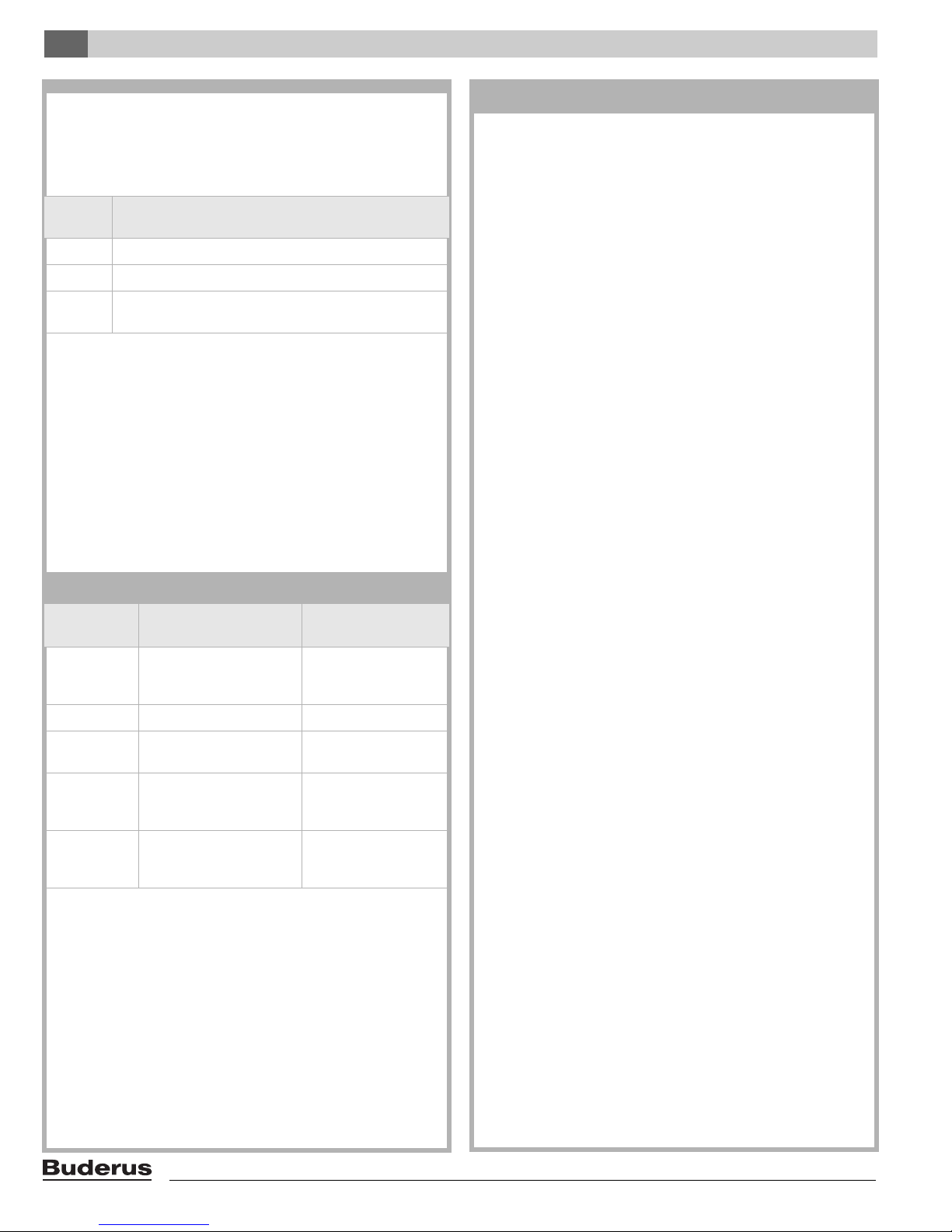
section 15
The manual operation mode enables the boiler to be run
manually for a long period. Manual operation should be used for
situations where the controller has not been installed yet, or
where the controller is out of order. See also section 22,
"Manual Operation menu", page 15.
A maximum heating system supply temperature in accordance
with the setting of the space heating water temperature knob
(section 14, [8]) on the BC 10 applies during the flue gas test,
service and manual operation.
DAMAGE TO THE INSTALLATION
with floor heating: by the pipework being overheated.
Use the space heating water temperature
knob [8] to limit the maximum heating system
supply temperature to the permitted heating
system supply temperature of the floor heating
circuit. This is usually approximately 104 °F
(40 °C).
DAMAGE TO THE INSTALLATION
due to frost while manual operation is switched on.
After a power failure or after switching off the main
voltage, the heating system may freeze since manual operation is no longer active.
Re-activate manual operation after switching on
the heating system, so that the system is permanently in operation.
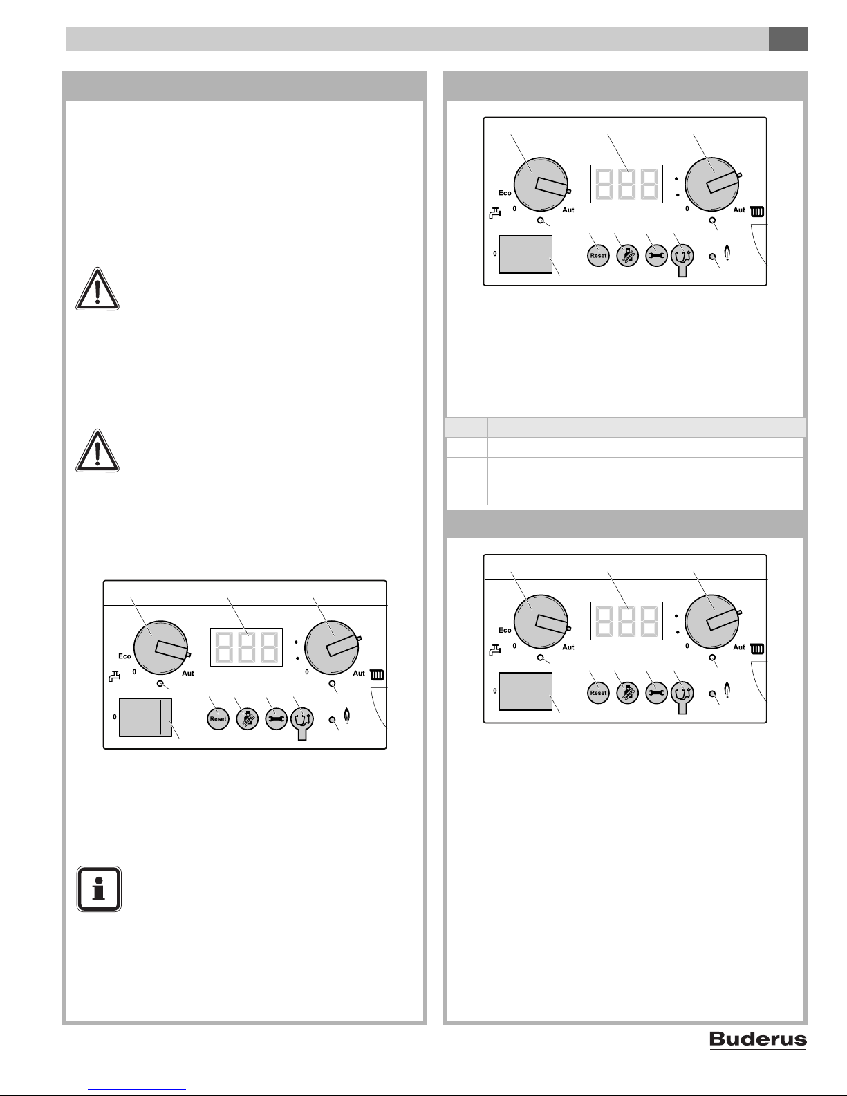
section 16
LED "Burner operation"
The LED "Burner operation" [6] lights up when the burner of the
heating boiler is active and it is extinguished when the burner is
no longer in operation.
The LED "Burner operation" indicates the burner status.
LED Status Explanation
On Burner operational The heating water is being heated.
The heating water has reached the
Off Burner off
required temperature range and there
is no heat demand.
section 17
"Service" button
The "Service" button [4] is used to display the heating system
supply temperature, the water pressure on the heating system
etc. See also section 27 "Display readings", section 28 "Display
settings" and section 29 "Display codes and other symptoms".
USER INSTRUCTION
If there is a risk of radiators or pipe sections freezing
up, we recommend setting the pump run-over time
to 24 hours. See section 28 "Display settings".
Logamax plus GB162-80 kW/100 kW - Subject to modifications resulting from technical improvements!
LED "Central heat demand"
The LED "Central heat demand" [7] lights up as soon as there
is a heat demand from the control system and is extinguished
as soon as there is no longer a heat demand.
11
Page 12
Operation4
Space heating water temperature knob
The Space heating water temperature knob [8] is used to set the
maximum heating system supply temperature. The unit is °F.
See table 2.
Knob
position
85–194 The maximum heating system supply temperature in °F.
Aut
table 2
1)
Display
The display [9] can show display readings, display settings and
display codes. If a fault occurs the display will immediately show
the accompanying fault code. If a locking fault has occurred, the
display code will flash.
Explanation
0 Heating mode off (but still DHW operation possible).
The maximum heating system supply temperature is
1)
194 °F (90 °C).
for use with Buderus controls
section 18 Menu structure
The boiler menu structure can be browsed on the BC10 using
the "Reset", "Chimney sweep" or "Service" buttons (section 17,
[2], [3] and [4]) and the display (section 17, [9]).
The boiler menu structure consists of 5 menus:
– Normal Operation menu (section 19, page 13);
– Flue Gas Test menu (section 20, page 13);
– Service Mode menu (section 21, page 14);
– Manual Operation menu (section 22, page 15);
– Settings menu (section 23, page 15).
DHW temperature knob
The DHW temperature knob [10] is used to set the DHW
temperature as required. The unit is °F. See table 3.
Knob
position
0
ECO Do not use this setting!
85–115
115 – 140
Aut
Meaning
DHW mode is off (but
heating operation may still
be possible).
The required DHW
temperature in °F.
The required DHW
temperature in °F.
The required DHW
1)
temperature is 140 °F
(60 °C).
Legionella
indication
Legionella propagation
ruled out
Very low risk if hot water
is used daily
Legionella propagation
ruled out. This position is
recommended.
Legionella propagation
ruled out.
table 3
1)
for use with Buderus controls
LED "DHW demand"
The LED "DHW demand" [11] lights up as soon as water is
being heated as the result of a hot water demand and is extinguished as soon as the heating system for DHW mode is
switched off.
12
Logamax plus GB162-80 kW/100 kW - Subject to modifications resulting from technical improvements!
Page 13
Operation 4
section 19 Normal Operation menu
Step 1 [\/7/5| Display reading: Currently measured heating system supply temperature in °F.
See also section 27 "Display readings", page 21.
Step 2 Continue in Normal Operation menu? Yes:
Step 3
Step 4 [p/2/2| Display reading: Currently measured heating system water pressure in PSI.
Step 5 Press the "
Step 6 [-/h/\| Random operating code. In this case: Operating code: The boiler is in heating mode.
Step 7 Have at least 5 seconds passed without a button being pressed and/or has the main voltage been interrupted ? Yes:
Step 8 Press the "e" button. → Step 1
Press the "
e" button.
See also section 27 "Display readings", page 21.
e" button.
See also section 29 "Display codes and other symptoms", page 21, and further.
section 20 Flue Gas Test menu
Step 1 [\/7/5| Display reading: Currently measured heating system supply temperature in °F.
See also section 27 "Display readings", page 21.
Step 2 Activate flue gas test? Yes:
Step 3 To activate the flue gas test:
Press and hold the "
Step 4
Step 5 Press the "
Step 6
Step 7 Press the "
Step 8
Step 9 Press the "
Step 10
Step 11 Have 30 minutes passed or has the main voltage been interrupted? Yes:
Step 12 Deactivate flue gas test? Yes:
Step 13 To deactivate the flue gas test:
[\/7/5] Display reading: Current heating system supply temperature in °F.
As soon as a non
activated. This means that the boiler is in heating mode at a capacity of 100 % for a maximum period of 30 minutes.
The maximum heating system supply temperature set on the control panel now applies. DHW mode is not possible
during the flue gas test.
e" button.
[p/2/2| Display reading: Currently measured heating system water pressure in PSI.
See also section 27 "Display readings", page 21.
e" button.
[-/a/\] Operating code: A flue gas test is being carried out or the boiler is in service mode.
Flue gas test: The boiler is in heating mode at a capacity of 100 % for a maximum of 30 minutes.
The maximum heating system supply temperature set on the control panel now applies.
Service mode: The boiler is in heating mode at a reduced capacity for a period of 30 minutes.
The maximum heating system supply temperature set on the control panel now applies.
DHW mode is not possible during the flue gas test or during service mode.
See also section 29 "Display codes and other symptoms", page 21.
e" button.
[\/7/5] Display reading: Currently measured heating system supply temperature in °F.
See also section 27 "Display readings", page 21.
Press and hold the "
d" button for more than 2 but not longer than 5 seconds.
-flashing dot is shown in the bottom right-hand corner of the display, the flue gas test has been
d" button for more than 2 seconds until the dot disappears.
→ Step 3
No: → Step 1
→ Step 1
No: → Step 8
→ Step 3
→ Step 1
No:
→ Step 1
No:
→ Step 12
→ Step 13
No:
→ Step 5
→ Step 1
Logamax plus GB162-80 kW/100 kW - Subject to modifications resulting from technical improvements!
13
Page 14
Operation4
section 21 Service Mode menu
Step 1 [\/7/5| Display reading: Currently measured heating system supply temperature in °F.
See also section 27 "Display readings", page 21.
Step 2 Activate service mode? Yes:
No:
Step 3 To activate service mode, step 1:
Press and hold the "
Step 4
Step 5 To activate service mode, step 2:
Step 6
Step 7 Press and hold the "
Step 8
Step 9 Press the "
Step 10
Step 11 Press the "
Step 12
Step 13 Press the "
Step 14
Step 15 Press the "
Step 16
Step 17 Press the "
Step 18
Step 19 Press the "
Step 20
Step 21 Have 30 minutes passed or has the main voltage been interrupted? Yes:
Step 22 Service mode is deactivated.
Step 23 Deactivate service mode? Yes:
Step 24 To deactivate the service mode:
Step 25 The boiler performance is then reduced according to the settings made in the "Settings" menu
[\/7/5] Display reading: Currently measured heating system supply temperature in °F.
As soon as a non
mode at 100 % performance for a maximum of 30 minutes. The maximum heating system supply temperature set
on the control panel now applies. DHW mode is not possible during service mode operation.
Press and hold the "
[l/?/?] Display setting: Maximum capacity setting during heating mode as a %.
See also section 28 "Display settings", page 21. In this case:
Service mode has been activated. You can now temporarily lower the boiler performance to partial load to check and if relevant adjust- the gas/air ratio or the ionization current.
[l/2/0] with a 100 kW boiler.
[l/2/0] or [l/2/5] Display setting: Minimum capacity setting during service mode as a %.
Within a couple of seconds the boiler will be modulated back to 20 % of its capacity in case of an 80 kW boiler and
25 % in case of a 100 kW boiler. The maximum heating system supply temperature set on the control panel now
applies (section 1, [4]). Check the gas/air ratio or the ionization current and if necessary set the gas/air ratio
according to section section 119 "Measuring and adjusting the gas/air ratio", page 84 or section 104 "Measure the
ionization current", page 76.
e" button.
[f/\5] Display setting: required pump run-over time after the end of the heating operation in minutes.
See also section 28 "Display settings", page 21.
e" button.
[c/\1] Display setting: required DHW mode position (on/off).
This setting has priority over -for example- a possible DHW mode (On/Off) setting on a room thermostat.
See also section 28 "Display settings", page 21.
e" button.
[\/7/5] Display reading: Currently measured heating system supply temperature in °F.
See also section 27 "Display readings", page 21.
e" button.
[p/2/2| Display reading: Currently measured heating system water pressure in PSI.
See also section 27 "Display readings", page 21.
e" button.
[-/a/\] Operating code: The boiler is in service mode.
See also section 29 "Display codes and other symptoms", page 21, and further.
e" button.
[\/7/5] Display reading: Currently measured heating system supply temperature in °F.
See also section 27 "Display readings", page 21.
Press and hold the "
page 15.
d" button for more than 2 but not longer than 5 seconds.
-flashing dot is shown in the bottom right-hand corner of the display, the boiler will run in heating
d"+ "e" buttons for more than 2 seconds.
[l/?/?] = 100 %
c" button until the display shows for boilers at sea level [l/2/5] with a 80 kW boiler or
See also section 28 "Display settings", page 21.
No:
No:
d" button for more than 2 seconds until the dot disappears.
in section 23,
→ Step 3
→ Step 1
→ Step 22
→ Step 23
→ Step 25
→ Step 24
→ Step 15
→ Step 1
14
Logamax plus GB162-80 kW/100 kW - Subject to modifications resulting from technical improvements!
Page 15
Operation 4
section 22 Manual Operation menu
Step 1 [\/7/5| Display reading: Currently measured heating system supply temperature in °F
See also section 27 "Display readings", page 21.
Step 2 Activate manual operation? Yes:
No:
Step 3 To activate manual operation:
Press and hold the "
Step 4
Step 5 Press the "
Step 6
Step 7 Press the "
Step 8
Step 9 Press the "
Step 10
Step 11 Has the main voltage been interrupted? Yes:
Step 12 Deactivate manual operation? Yes:
Step 13 To deactivate manual operation:
[\7/5}Display reading: Currently measured heating system supply temperature in °F.
As soon as a flashing dot is shown in the bottom right-hand corner of the display, manual operation is active. This
means that the boiler is permanently in heating mode. The maximum heating system supply temperature set on the
control panel now applies (section 1, [4]). The LED "Central heat demand" lights up.
e" button.
[p/2/2}Display reading: Currently measured heating system water pressure in PSI.
See also section 27 "Display readings", page 21.
e" button.
[-/h/\| Operating code. The device is in manual operation mode. See also section 29 "Display codes and other
symptoms", page 21. During manual operation the "Settings" menu in section 23 from step 3 can be used to
temporarily change the target boiler performance. DHW mode is possible during manual operation.
CAUTION: If the boiler performance has been changed temporarily, it must be reset after ending manual operation,
according to the "Settings" menu, section 23, page 15
e" button.
[\7/5}Display reading: Currently measured heating system supply temperature in °F.
See also section 27 "Display readings", page 21.
Press and hold the "
d" button for more than 5 seconds.
No:
No:
d" button for more than 2 seconds until the dot disappears.
→ Step 1
→ Step 1
→ Step 1
→ Step 12
→ Step 13
→ Step 5
→ Step 1
section 23 Settings menu
Step 1 [\/7/5| Display reading: Currently measured heating system supply temperature in °F.
See also section 27 "Display readings", page 21.
Step 2 Open the "Settings" menu? Yes:
No:
Step 3 To open the Settings menu:
Press and hold the "
Step 4
Step 5 Adjust boiler performance? No:
Step 6 Lower: Decrease the target boiler performance with the "
Step 7 Press the "
Step 8
[l/?/?| Display setting: target boiler performance as a %.
See also section 28 "Display settings", page 21.
As soon as the display shows
parameter shown on the display.
[l/2/5| = 25 % for an 80 kW heating boiler and [l/2/0| = 20 % for a 100 kW heating boiler.
Higher: Increase the target boiler performance with the "
Otherwise, this concerns the factory-adjusted setting.
e" button.
[f/\5] Display setting: Target pump run-over time after heating mode has elapsed in minutes.
Set the second parameter as soon as the display shows
Recommendation: Do not set a pump run-over time of less than
d"+ "e" buttons for more than 2 seconds.
[l/?/?|, the "Settings" menu is open. The boiler performance can be set using the first
Yes:
c" button. The minimum setting for boilers at sea level is
d" button. The maximum setting is [l/?/?| = 100 %.
[f/\/5|.
[f/\/5| (= 5 minutes).
→ Step 3
→ Step 1
→ Step 7
→ Step 6
Logamax plus GB162-80 kW/100 kW - Subject to modifications resulting from technical improvements!
15
Page 16
Operation4
section 23 Settings menu (continued)
Step 9 Set the pump run-over time after heating operation has ended? Yes: → Step 10
No:
→ Step 11
Step 10 Lower: Decrease the target pump run-over time after the end of heating operation with the "
The minimum setting is
Higher: Increase the target pump run-over time after the end of heating operation with the "
The minimum setting is
Step 11 Press the "
Step 12
Step 13 Set the DHW mode status? Yes:
Step 14 Set the DHW mode On or Off with the "
Step 15 Have at least 5 seconds passed without a button being pressed and/or has the main voltage been interrupted ? Yes:
Step 16 Press the "
Step 17
[c/\1] Display setting: required DHW mode position (on/off).
Set the third parameter as soon as the display shows
Note! If
[\/7/5| Display reading: Currently measured heating system supply temperature in °F.
Any adjustments that you have made have been confirmed.
e" button.
See also section 28 "Display settings", page 21.
[c/\/0| is set, the frost protection for the internal or external hot water tank heater is switched off.
e" button.
See also section 27 "Display readings", page 21.
[f/\/0| = 0 minutes. The factory default setting is 5 minutes.
[f/1/d| = 24 hours.
[c/\/1|.
c" or "d" buttons. [c/\/1| is "On", [c/\/0| is "Off".
c" button.
d" button.
No:
No:
→ Step 14
→ Step 15
→ Step 17
→ Step 16
→ Step 1
16
Logamax plus GB162-80 kW/100 kW - Subject to modifications resulting from technical improvements!
Page 17
Operation 4
section 24 Operation
Start-up phase
Step 1 Switch “On” the power supply to the boiler.
Step 2 Turn the main power switch on the BC10 to position "1" (On), also see section 14.
Step 3 The LED of the UBA 3 (section 1, [32]) lights up for 1 second. This means that the UBA 3 is reading the KIM.
Step 4
Step 5
Step 6
Step 7 Press the "
Step 8 [p/2/2| Display reading: Currently measured heating system water pressure in PSI.
Step 9 Press the "
Step 10 [0/u/\| Operating code: The boiler starts up after activation of the mains power supply or completion of a
Step 11 Has the air-side pre-purge phase been completed without any problems? Yes:
Step 12 Now remedy the fault by following the section relating to the error code that is now displayed. See also section 29.
Step 13 [0/h/\| Operating code. The boiler is in standby mode. No current heat requirement.
Step 14 Start of pump over-run time for the heating system. The pump over-run time for the heating system can be adjusted
Step 15 Has the preset pump over-run time expired? Yes:
Step 16 Is there a DHW heating system which has generated a heat demand? Yes: → Step 29
Step 17 Is there a current heat demand from the room or external temperature-dependent controller? Yes: → Step 48
Step 18 Is the current heating-system supply temperature lower than 45 °F (7 °C)? Yes: → Step 65
Step 19 The pump stops.
Step 20 Has the pump been out of use for more than 24 hours? Yes:
Step 21 Is there a DHW heating system which has generated a demand? Yes: → Step 29
When installing a new KIM or a new UBA 3, the LED will flash at a high frequency for max. 10 seconds while the data
is being exchanged.
[8.8.8] Operating code: The display is tested during starting up, immediately after switching on the main
voltage. This code is displayed for a maximum of 1 second.
See also section 29 "Display codes and other symptoms", page 21.
[\/-/\| Operating code: A communication test is carried out during starting up.
This display code flashes to check the communication between the UBA 3 (section 1, [32]) and the
control panel (section 1, [4]) for 3-5 times during a period of 3-5 seconds while starting up.
If a new UBA3 or a new KIM was fitted, this code will flash for max. 10 seconds.
See also section 29 "Display codes and other symptoms", page 21.
[\/7/5| Display reading: Currently measured heating system supply temperature in °F.
See also section 27 "Display readings", page 21.
e" button.
See also section 27 "Display readings", page 21.
e" button.
system reset.
Start of water-side flow check: The pump will carry out max. 4 attempts to restore the water flow.
Start of air-side pre-purge phase. The fan unit runs at about 60 % of maximum speed for 15 seconds.
See also section 29 "Display codes and other symptoms", page 21.
→ Step 13
No: → Step 12
→ Step 1
As soon as a locking fault occurs (indicated by a flashing display code), the pump is activated to run continuously,
thus minimizing the risk of the heating system freezing up.
Readiness for operation
See also section 29 "Display codes and other symptoms", page 21.
as per section 23. Factory-adjusted setting: 5 minutes
→ Step 19
No: → Step 16
No: → Step 17
No: → Step 18
No: → Step 15
→ Step 24
No: → Step 21
No: → Step 22
Logamax plus GB162-80 kW/100 kW - Subject to modifications resulting from technical improvements!
17
Page 18
Operation4
section 24
Step 22 Is there a current heat demand from the room or external temperature-dependent controller? Yes: → Step 48
No: → Step 23
Step 23 Is the current heating-system supply temperature lower than 45 °F (7 °C)? Yes: → Step 65
No: → Step 20
Step 24 The pump is run for 10 seconds in order to prevent it from seizing up.
Step 25 Have ten seconds elapsed? Yes:
Step 26 Is there a DHW heating system which has generated a demand? Yes: → Step 29
Step 27 Is there a current heat demand from the room or external temperature-dependent controller? Yes: → Step 48
Step 28 Is the current heating-system supply temperature lower than 45 °F (7 °C)? Yes:
DHW operating phase
Step 29 The LED "DHW demand" on the control panel (section 1, [4]) lights up.
Step 30
Step 31
Step 32 Maximum four ignition attempts are carried out. Does the ionization current exceed 1.4 microamperes within these
Step 33 [-/h/\| Operating code: The device is in DHW mode.
Step 34 Is there still a heat demand? Yes:
Step 35 Is the heating-system supply temperature 45 °F (25 °C) higher than the preset DHW temperature or higher than
Step 36 [0/y/\| Operating code: The supply temperature sensor has measured a current heating supply temperature
Step 37 The LED "Burner operation" is extinguished.
Step 38 The fan unit (section 1, [20]) continues to run for max. 30 seconds.
Step 39 Has the heating system supply temperature fallen sufficiently? Yes:
Step 40 The gas valve (section 1, [21]) is closed and the burner is shut down.
Step 41 The LED "Burner operation" is extinguished.
Step 42 The LED "DHW demand" is extinguished.
Step 43
Step 44 Have approx. 30 seconds elapsed? Yes:
[0/c/\| Operating code. The boiler prepares for a burner start-up whenever a heat demand arises. The fan unit
(section 1, [20]) and the pump are started. The glow ignitor (section 1, [27]) is activated.
[0/l/\| Operating code. The gas valve (section 1, [21]) is activated.
See also section 29 "Display codes and other symptoms", page 21.
4 ignition attempts?
See also section 29 "Display codes and other symptoms", page 21.
The LED "Burner operation" on the control panel (section 1, [4]) lights up. The startup load on the boiler is approx.
50 % for the purposes of flow monitoring and is then modulated up or down. The degree of modulation of the pump
will hardly vary during DHW mode; the pump will be running almost continuously at 100 %.
200°F (93°C)?
higher than the supply temperature setting on the control panel (section 1, [4]), or higher than the
supply temperature calculated according to the heating curve or higher than the supply temperature
calculated according to the DHW mode.
[0/h/\| Operating code. The boiler is in standby mode. There is no current heat demand.
Start of pump over-run time via the tank for a period of approx. 60 seconds.
Start of air-side purging phase of the fan unit (section 1, [20]) for approx. 30 seconds.
See also section 29 "Display codes and other symptoms", page 21.
→ Step 19
No: → Step 26
No: → Step 27
No: → Step 28
→ Step 65
→ Step 25
No:
→ Step 33
Yes:
No: → Step 12
→ Step 35
No: → Step 40
Yes: → Step 36
No: → Step 33
→ Step 29
No: → Step 39
→ Step 45
No: → Step 44
18
Logamax plus GB162-80 kW/100 kW - Subject to modifications resulting from technical improvements!
Page 19
Operation 4
section 24
Step 45 The fan unit (section 1, [20]) stops.
Step 46 Have approx. 60 seconds elapsed? Yes: → Step 47
No: → Step 46
Step 47 The pump stops. See also section 29 "Display codes and other symptoms", page 21.
Boiler operating phase
Step 48 The LED "Central heat demand" lights up.
Step 49
Step 50
Step 51 Maximum of four ignition attempts are carried out. Does the ionization current exceed 1.4 microamperes within these
Step 52 [-/h/\| Operating code. The device is in heating mode.
Step 53 Is there still a heat demand from the room or external temperature-dependent controller? Yes:
Step 54 Is the heating-system supply temperature higher than the target setting?
Step 55
Step 56 The LED "Burner operation" is extinguished.
Step 57 The fan unit (section 1, [20]) continues to run for max. 30 seconds.
Step 58 Has the heating system supply temperature fallen sufficiently? Yes:
Step 59 The LED "Central heat demand" is extinguished.
Step 60
Step 61 The LED "Burner operation" is extinguished.
Step 62 Start of pump over-run time for the heating system. The pump over-run time for the heating system can be adjusted
Step 63 Have approx. 30 seconds elapsed? Yes:
Step 64 The fan unit (section 1, [20]) stops. → Step 15
[0/c/\| Operating code. The boiler prepares for a burner start-up whenever a heat demand arises. The fan
unit (section 1, [20]) and the pump are started. The glow ignitor (section 1, [27]) is activated.
See also section 29 "Display codes and other symptoms", page 21.
[0/l/\| Operating code. The gas valve (section 1, [21]) is activated.
See also section 29 "Display codes and other symptoms", page 21.
4 ignition attempts?
See also section 29 "Display codes and other symptoms", page 21.
The LED "Burner operation" on the control panel (section 1, [4]) lights up. The startup load on the boiler is approx.
50 % for the purposes of flow monitoring and is then modulated up or down. The pump modulation degree will vary
strongly during heating operation.
When working with an external temperature-dependent controller, the target setting is calculated by the controller;
when working with a room temperature control device it is set on the control panel (section 1, [4]).
[0/y/\| Operating code: The supply temperature sensor as measured a current heating supply temperature
higher than the supply temperature setting on the control panel (section 1, [4]), or higher than the
supply temperature calculated according to the heating curve or higher than the supply temperature
calculated according to the DHW mode.
See also section 29 "Display codes and other symptoms", page 21.
[0/h/\| Operating code. The boiler is in standby mode. There is no current heat demand.
See also section 29 "Display codes and other symptoms", page 21. The gas valve (section 1, [21]) is closed
and the burner (section 1, [23]) is shut down.
as per section 23. Factory-adjusted setting: 5 minutes.
Start of air-side flushing phase of the fan unit (section 1, [20]) for approx. 30 seconds.
→ Step 52
Yes:
No: → Step 12
→ Step 54
No: → Step 59
Yes:
→ Step 55
No: → Step 52
→ Step 49
No: → Step 58
→ Step 64
No: → Step 63
Logamax plus GB162-80 kW/100 kW - Subject to modifications resulting from technical improvements!
19
Page 20
Operation4
Frost-protection operating phase
Step 65 The LED "Central heat demand" lights up.
Step 66
Step 67
Step 68 Maximum of four ignition attempts are carried out. Does the ionization current exceed 1.4 microamperes within these
Step 69 [-/h/\| Operating code: The device is in heating mode.
Step 70 Is the current heating-system supply temperature higher than 59 °F (15 °C)? Yes:
[0/c/\| Operating code. The boiler prepares for a burner start-up whenever a heat demand arises.
The fan unit (section 1, [20]) and the pump are started. The glow ignitor (section 1, [27]) is activated.
See also section 29 "Display codes and other symptoms", page 21.
[0/l/\| Operating code. The gas valve (section 1, [21]) is activated.
See also section 29 "Display codes and other symptoms", page 21.
4 ignition attempts?
See also section 29 "Display codes and other symptoms", page 21.
The LED "Burner operation" is lit up. The boiler is in heating mode.
Yes:
No: → Step 12
No:
→ Step 69
→ Step 59
→ Step 69
20
Logamax plus GB162-80 kW/100 kW - Subject to modifications resulting from technical improvements!
Page 21
Symptoms 5
5 Symptoms
section 25 Symptoms
You can find a further explanation of the symptoms in section 6 on page 6.
section 26 Removing the control panel
To make it easier to operate the BC10 when the boiler door is open and to make it easier to read the display, the BC10 can be
temporarily attached to the boiler in a suspended position while carrying out service activities. See section 68, page 56.
section 27 Display readings
Display
reading
[\/7/5|
[p/2/2|
section 28 Display settings
Display
setting
[l/9/9|
[l/9/9|
[f/\/5|
[c/\/1|
Meaning Unit Range
Display reading Current heating system supply
temperature in °F.
Display reading Current heating system water
pressure in PSI.
Meaning Unit Range
Display setting: Logamax plus GB162-80 kW target
boiler performance as a %
Display setting: Logamax plus GB162-100 kW
target boiler performance as a %
Display setting: Target pump over-run time in
minutes after heating mode has ended.
Recommendation:Do not set a pump over-run time
of less than
Display setting: required DHW supply position
(on/off). This setting has priority over -for examplea possible DHW mode (On/Off) setting on a room
thermostat.
Note! If the setting
protection of the DHW heating system has also been
switched off.
[f/\/5| (= 5 minutes).
[c/\/0| has been made, the frost
°F
PSI
%
%
Min.
[\/4/8|
[p/0/0|
[l/2/5|
[l/2/0|
[f/0/0|
–
–
–
–
–
[2/6/6|
[p/5/8|
[l/9/9|
[l/9/9|
[f/6/0|
[c/\/0|
"Off" /
/
/
/
[l/?/?]
[l/?/?]
[f/1/d|
[c/\/1|
100 %
100 %
24 hours
"On"
Factory
setting
[l/?/?]
[l/?/?]
[f///5|
[c/\/1|
section 29 Display codes and other symptoms
Display code LED on
Main
display
z
code
Logamax plus GB162-80 kW/100 kW - Subject to modifications resulting from technical improvements!
z
Sub-
display
code
Meaning
z
No display code Off No indication on the display of
No display code Off On devices with DHW opera-
No display code Off On devices with DHW opera-
No display code Off No indication on the display of
Reset
required?
UBA 3
Other symptoms Diagnosis
the BC10 (section 1, [4]).
tion:
no or insufficient DHW;
radiators, convectors, etc. may
be heated without current heat
demand.
tion:
hot water may be available, no
heating operation.
On devices without DHW
operation:
no heating operation.
the BC10 (section 1, [4]).
→ section 31
→ section 32
→ section 33
→ section 34
21
Page 22
Symptoms5
section 29 Display codes and other symptoms
Display code LED on
z
e
e
Main
display
code
[\/-/\|
[\/-/\|
[\/\/\]
[\/\/}
[-/a/\]
2)
[-/h/\|
z
e
e
Sub-
display
code
[2/0/8|
1)
[2/0/0|
1)
Meaning
z
Operating code: A communication test is carried out while starting up. This display code
flashes to check the communication between
the UBA 3 (section 1, [32]) and the control
panel (section 1, [4]) 3-5 times during a period
of 3-5 seconds while starting up. If a new UBA
3 or a new KIM has been fitted, this display
code will flash for max. 10 seconds.
Fault code: If this code continues to flash on
the display, there is a fault in the communication between the UBA 3 (section 1, [32]) and
the control panel (section 1, [4]).
Operating code:The boiler is in flue gas test
or service mode.
Flue gas test: The boiler is in heating mode at
a performance capacity of 100 % for a period
of 30 minutes. The maximum heating system
supply temperature set on the control panel
now applies (section 1, [4]).
Service mode: the boiler will run in heating
mode at a reduced performance capacity for
30 minutes. The maximum heating system
supply temperature set on the control panel
now applies (section 1, [4]).
DHW mode is not possible during the flue gas
test or during service mode.
Operating code: The boiler is in manual operation mode.
Operating code:The boiler is in flue gas test
or service mode.
Flue gas test: the boiler will run in heating
mode at 100 % performance capacity for
30 minutes. The maximum heating system
supply temperature set on the control panel
now applies (section 1, [4]).
Service mode: the boiler will run in heating
mode at a reduced performance capacity for
30 minutes. The maximum heating system
supply temperature set on the control panel
now applies (section 1, [4]).
DHW mode is not possible during the flue gas
test or during service mode.
Operating code: The boiler is in heating
mode.
Reset
required?
Other symptoms Diagnosis
UBA 3
Off or
flashing
at 8 Hz
Off or
flashing
at 8 Hz
No heating operation and no
DHW.
Off No DHW operation.
Off
Off No DHW operation.
Off
→ section 66
e
e
e
e
[-/h/\|
[=/h/\|
[0/a/\|
[0/a/\|
e
[2/0/0|
3)
e
e
e
1)
[2/0/1|
1)
[2/0/2|
1)
[3/0/5|
1)
22
Operating code: The boiler is in manual operation mode.
Operating code: The boiler is in DHW mode. Off
Operating code:The switch optimization pro-
gram is activated. This program is activated if
a hot water request from an RC regulator or an
ON/OFF controller occurs more frequently
than once every 10 minutes. This means that
the boiler cannot be restarted until at least
ten minutes have elapsed since initial startup
of the burner.
Operating code:The heating boiler cannot
start up temporarily after DHW mode has
ended.
Logamax plus GB162-80 kW/100 kW - Subject to modifications resulting from technical improvements!
Off
Off The target room temperature
possibly is not reached.
Off
→ section 35
Page 23

section 29 Display codes and other symptoms
Display code LED on
z
e
e
e
Main
display
code
[0/c/\|
[0/e/\|
[0/h/\|
z
e
e
e
Sub-
display
code
[2/8/3|
1)
[2/6/5|
1)
[2/0/3|
1)
Meaning
z
Operating code:The heating boiler prepares
for a burner start-up whenever a heat demand
has occurred. The fan unit (section 1, [22]) and
the pump are started.
The glow ignitor (section 1, [29]) is activated.
Operating code: The time-proportional program is activated.
The time-proportional program is activated as
soon as the required modulating control performance is lower than the bottom limit of the
device performance.
During the time-proportional program the
burner (section 1, [4]) is switched on and off
repeatedly during a period of 10 minutes. The
period in which the burner is switched on
depends on the difference between the
required performance of the modulating control and the lower limit of the device performance. As soon as the burner has been
switched on, the boiler runs at minimum
capacity and the display of the control panel
(section 1, [4]) shows [-/h/\|.
As soon as the burner is switched off, the operating code [0/e/\| is indicated in the display.
Example: The device performance is 25 kW,
the bottom limit of the device performance is at
20 % and the required modulating control performance is 5 %. This means that the burning
time is then a quarter of the total time frame of
10 minutes, i.e. the burning time is 2.5 minutes. The Off time is then 10 min. - 2.5 min. =
7.5 min.
Operating code: The boiler is in standby
mode. No heat demand is created.
Symptoms 5
Other symptoms Diagnosis
UBA 3
Reset
required?
Off
Off
Off
e
e
e
e
e
[0/l/\|
[0/u/\|
[0/y/\|
[0/y/\|
[0/y/\|
e
e
e
e
e
[2/8/4|
1)
[2/7/0|
1)
[2/0/4|
1)
[2/7/6|
[2/7/7|
Operating code: The gas valve (section 1,
[21]) is activated.
Operating code: The boiler starts up after
activation of the mains power supply or completion of a system reset.
Start of the water-side supply check:
The pump will carry out max. 4 attempts to
restore the water flow.
Start of air-side pre-purging phase:
The fan (section 1, [20]) runs for 15 seconds at
about 60 % of its maximum speed (applies to
all Logamax plus GB162 devices).
This code is displayed for a maximum of
4 minutes.
Operating code: The supply temperature
sensor (section 1, [24]) has detected that the
current heating-system supply temperature is
higher than the temperature entered at the
control panel (section 1, [4]), or that it is higher
than the heating-system supply temperature
calculated according to the heating curve, or
that it is higher than the heating-system supply
temperature calculated for DHW mode.
Blocking fault code: The supply temperature
e
sensor (section 1, [24]) has measured a current heating supply temperature higher than
203 °F (95 °C).
Blocking fault code: The safety temperature
e
sensor (section 1, [28]) has measured a current supply temperature higher than 203 °F
(95 °C).
No
5) 7)
No
5) 7)
Off
Off
Off The target room temperature
possibly is not reached.
Off The target room temperature
possibly is not reached.
Possibly no DHW operation.
Off The target room temperature
possibly is not reached.
Possibly no DHW operation.
→ section 36
→ section 37
→ section 37
Logamax plus GB162-80 kW/100 kW - Subject to modifications resulting from technical improvements!
23
Page 24

Symptoms5
section 29 Display codes and other symptoms
Display code LED on
z
e
e
e
e
e
e
e
e
e
e
e
e
e
Main
display
code
[0/y/\|
[1/a/\|
[1/c/\|
[1/u/\|
[1/y/\|
[2/e/\|
[2/f/\|
[2/f/\|
[2/l/\|
[2/p/\|
[2/u/\|
[2/y/\|
[2/y/\|
z
e
e
e
e
e
e
e
e
e
e
e
e
e
Sub-
display
code
[2/8/5|
[3/1/6|
[2/1/0|
[3/1/7|
[3/1/8|
[2/0/7|
[2/6/0|
[2/7/1|
[2/6/6|
[2/1/2|
[2/1/3|
[2/8/1|
[2/8/2|
Meaning
z
Blocking fault code:The return temperature
e
sensor (section 1, [31]) has measured a current return water temperature higher than
203 °F (95 °C).
Locking fault code: The flue gas sensor tem-
e
perature is too high.
Locking fault code: The safety temperature
e
switch has measured an excessively high temperature and is open, or no connection is made
between contacts 50 and 78 of the UBA 3
mounting base.
CAUTION: The boiler can have a flue gas thermostat or a connection between contacts 50
and 78 of the UBA 3 mounting base, depending on the boiler type.
Locking fault code: The flue gas sensor con-
e
tacts have shorted.
Locking fault code: The flue gas sensor con-
e
tacts are open.
Blocking fault code: The heating system
e
water pressure is too low and is less than
3 PSI. Neither the boiler nor the pump are
started up.
As soon as the water pressure of the heating
system is 14 PSI or more, the display code
[2/e/\| [2/0/7| will disappear and both the boiler
and the pump will start running.
As soon as the water pressure of the heating
system is less than 6 PSI, the boiler performance for both the heating operation and the
DHW mode will be limited.
Blocking fault code: The supply temperature
e
sensor (section 1, [24]) has not measured any
heating water temperature increase after a
burner start.
Operating code blocking fault code:
e
The temperature difference of the heating
water measured between the supply
(section 1, [24]) and safety temperature sensors (section 1, [28]) is too much.
Locking fault code: The pressure sensor
e
(section 1, [30]) failed to measure a pressure
increase on the heating side during any of four
attempts.
Blocking fault code: The supply temperature
e
sensor (section 1, [24]) has measured
a heating water temperature increase of more
than 9 °F/sec (5 °C/sec).
Blocking fault code: The temperature differ-
e
ence measured between the supply temperature sensor (section 1, [24]) and the return
temperature sensor (section 1, [31]) is more
than 90 °F (50 °C).
Operating code:The pump speed was found
e
to be too high or too low while starting
up [0/u/\|.
The modulating function of the pump is
switched off. The pump continues to run, but
the pump speed is fixed.
Operating code: The tacho signal of the
e
pump is missing.
Other symptoms Diagnosis
UBA 3
Reset
required?
No
5) 7)
Yes
4) 6) 7) 8)
Yes
4) 6) 7) 8)
Yes
4) 6) 7) 8)
Yes
4) 6) 7) 8)
No Off No heating operation and no
No Off No heating operation and no
No Off No heating operation and no
Yes
4) 6) 7) 8)
No
5) 7)
No
5) 7)
No Off No heating operation and no
No Off No heating operation and no
Off The
target room temperature possibly is not reached.
Possibly no DHW operation.
flashing
flashing
flashing
flashing
flashing
No heating operation and no
1Hz
DHW.
No heating operation and no
1Hz
DHW.
No heating operation and no
1Hz
DHW.
No heating operation and no
1Hz
DHW.
DHW.
DHW.
DHW.
No heating operation and no
1Hz
DHW.
Off No heating operation and no
DHW.
Off No heating operation and no
DHW.
DHW.
DHW.
→ section 37
→ section 38
→ section 39
→ section 40
→ section 40
→ section 41
→ section 37
→ section 37
→ section 42
→ section 37
→ section 37
→ section 43
→ section 44
24
Logamax plus GB162-80 kW/100 kW - Subject to modifications resulting from technical improvements!
Page 25

section 29 Display codes and other symptoms
Display code LED on
z
e
e
e
e
e
e
e
e
e
e
e
e
e
e
e
Main
display
code
[3/a/\|
[3/c/\|
[3/f/\|
[3/l/\|
[3/p/\|
[3/y/\|
[4/a/\|
[4/c/\|
[4/e/\|
[4/f/\|
[4/l/\|
[4/p/\|
[4/u/\|
[4/y/\|
[5/c/\|
11)
z
e
e
e
e
e
e
e
e
e
e
e
e
e
e
e
Sub-
display
code
[2/6/4|
[2/1/7|
[2/7/3|
[2/1/4|
[2/1/6|
[2/1/5|
[2/1/8|
[2/2/4|
[2/7/8|
[2/1/9|
[2/2/0|
[2/2/1|
[2/2/2|
[2/2/3|
[2/6/8|
Meaning
z
Blocking fault code: The fan unit tacho signal
e
(section 1, [20]) or the fan unit voltage has
failed during the operating phase.
Locking fault code: The fan unit (section 1,
e
[20]) is running irregularly while starting up.
Blocking fault code: the boiler has been
e
switched off for a couple of seconds, since it
had been operational for 24 hours. This is a
safety check.
Locking fault code: The fan unit tacho signal
e
(section 1, [20]) or the fan unit main voltage is
not available during the pre-operative
phase [0/c/\|.
Locking fault code: The fan unit (section 1,
e
[20]) is running too slowly.
Locking fault code: The fan unit (section 1,
e
[20]) is running too fast.
Locking fault code: The supply temperature
e
sensor (section 1, [24]) has measured a heat-
ing supply temperature higher than 221 °F
(105 °C).
Locking fault code: The safety temperature
e
switch has measured an excessively high temperature and is open, or no connection is made
between contacts 22 and 24 of the UBA 3
mounting base.
The boiler can have a safety temperature
switch or a connection between contacts 22
and 24 of the UBA 3 mounting base, depending on the boiler type.
Locking fault code:The sensor test has
e
failed.
Locking fault code: The safety temperature
e
sensor (section 1, [28]) has measured a supply temperature higher than 221 °F (105 °C).
Locking fault code: The contacts of the
e
safety temperature sensor (section 1, [28])
have shorted to each other, the contacts of the
safety temperature sensor have shorted to
ground or the contacts of the safety temperature sensor have measured a supply water
temperature of over 266 °F (130 °C).
Locking fault code: The contacts of the
e
safety temperature sensor (section 1, [28]) are
open.
Locking fault code:The contacts of the sup-
e
ply temperature sensor (section 1, [24]) have
shorted.
Locking fault code: The contacts of the sup-
e
ply temperature sensor (section 1, [24]) are
open.
Operating code: The Service Tool was con-
e
nected at the time indicated.
Other symptoms Diagnosis
UBA 3
Reset
required?
No Off No heating operation and no
Yes
4) 6) 7) 8)
No
5) 7)
Yes
4) 6) 7) 8)
Yes
4) 6) 7) 8)
Yes
4) 6) 7) 8)
Yes
4) 6) 7) 8)
Yes
4) 6) 7) 8)
Yes
4) 6) 7) 8)
Yes
4) 6) 7) 8)
Yes
4) 6) 7) 8)
Yes
4) 6) 7) 8)
Yes
4) 6) 7) 8)
Yes
4) 6) 7) 8)
No Off
flashing
flashing
flashing
flashing
flashing
flashing
flashing
flashing
flashing
flashing
flashing
flashing
DHW.
No heating operation and no
1Hz
DHW.
Off → section 47
No heating operation and no
1Hz
DHW.
No heating operation and no
1Hz
DHW.
No heating operation and no
1Hz
DHW.
No heating operation and no
1Hz
DHW.
No heating operation and no
1Hz
DHW.
No heating operation and no
1Hz
DHW.
No heating operation and no
1Hz
DHW.
No heating operation and no
1Hz
DHW.
No heating operation and no
1Hz
DHW.
No heating operation and no
1Hz
DHW.
No heating operation and no
1Hz
DHW.
Symptoms 5
→ section 45
→ section 46
→ section 45
→ section 48
→ section 49
→ section 37
→ section 50
→ section 51
→ section 37
→ section 52
→ section 53
→ section 53
→ section 53
e
e
[5/h/\|
[5/h/\|
10)
e
[2/6/8|
1)
ee
Operating code: Component test phase using
e
the Service Tool.
Blocking fault code: There is no communication between RCC and UBA 3 (section 1, [32]).
Logamax plus GB162-80 kW/100 kW - Subject to modifications resulting from technical improvements!
No Off
No Off No heating operation.
25
Page 26
Symptoms5
section 29 Display codes and other symptoms
Display code LED on
z
e
e
e
e
e
e
e
e
Main
display
code
[5/l/\|
10)
[6/a/\|
[6/a/\|
[6/c/\|
[6/c/\|
[6/l/\|
[6/p/\|
[7/c/\|
Sub-
display
z
code
ee
e
[2/2/7|
e
[2/2/7|
e
[2/2/8|
e
[3/0/6|
e
[2/2/9|
e
[2/6/9|
e
[2/3/1|
Meaning
z
General fault code: A blocking or locking
boiler fault has occurred.
Blocking fault code: Insufficient flame activity
e
(ionization current) was measured during the
first, second or third burner ignition attempt
(section 1, [23]).
Locking fault code: Insufficient flame activity
e
(ionization current) was measured during the
fourth burner ignition attempt (section 1, [23]).
Locking fault code: Flames (ionization cur-
e
rent) were measured after a heat demand
occurred, but before opening the gas valve
(section 1, [21]).
Locking fault code: Flames (ionization cur-
e
rent) were detected after switching off the
burner (section 1, [23]).
Blocking fault code: Insufficient flame activity
e
(ionization current) was measured during the
burner procedure.
Locking fault code: The glow ignitor
e
(section 1, [29]) was activated too long (for
more than 10 minutes).
Locking fault code:
e
The power supply was interrupted during a
locking fault
[4/a/\| [2/1/8|, [4/c/\| [2/2/4|,
Reset
required?
Yes/No Off
No
5) 7)
Yes
4) 6) 7) 8)
Yes
4) 6) 7) 8)
Yes
4) 6) 7) 8)
No
5) 7)
Yes
4) 6) 7) 8)
Yes
4) 6) 7) 8)
Other symptoms Diagnosis
UBA 3
flashing
flashing
flashing
flashing
flashing
flashing
Possibly no heating operation
and no DHW.
1Hz
Off → section 54
No heating operation and no
1Hz
DHW.
No heating operation and no
1Hz
DHW.
No heating operation and no
1Hz
DHW.
Off No heating operation and no
DHW.
No heating operation and no
1Hz
DHW.
No heating operation and no
1Hz
DHW.
→ section 54
→ section 55
→ section 56
→ section 57
→ section 58
→ section 59
e
e
e
e
e
e
e
e
e
e
[7/h/\|
[7/l/\|
[7/l/\|
[8/y/\|
[8/8/8|
[9/a/\|
[9/h/\|
[9/h/\|
[9/h/\|
[9/l/\|
[9/l/\|
e
e
e
e
e
e
e
e
e
e
[3/2/8|
[2/6/1|
[2/8/0|
[2/3/2|
1)
[2/3/5|
[2/3/7|
[2/6/7|
[2/7/2|
[2/3/4|
[2/3/8|
[4/e/\| [2/7/8|, [4/f/\| [2/1/9|,
[4/l/\| [2/2/0|, [4/u/\| [2/2/2| or
[4/y/\| [2/2/3|.
Blocking fault code: The main voltage has
e
briefly been interrupted.
Locking fault code: The UBA 3 (section 1,
e
[32]) is defective.
Locking fault code: The UBA 3 (section 1,
e
[32]) is defective.
Operating code:The external switch contact
has opened.
Operating code: Display test while starting
up, immediately after switching on the main
voltage. This code is displayed for a maximum
of 1 second.
Locking fault code: The KIM is too new for
e
the UBA 3 (section 1, [32]).
Locking fault code: The UBA 3 (section 1,
e
[32]) or the KIM is defective.
Locking fault code: The UBA 3 (section 1,
e
[32]) or the KIM is defective.
Locking fault code: The UBA 3 (section 1,
e
[32]) or the KIM is defective.
Locking fault code: The contacts of the gas
e
valve (section 1, [21]) are open.
Locking fault code: The UBA 3 (section 1,
e
[32]) or the KIM is defective.
No
5) 7)
Yes
4) 6) 7) 8)
Yes
4) 6) 7) 8)
Yes
4) 6) 7) 8)
Yes
4) 6) 7) 8)
Yes
4) 6) 7) 8)
Yes
4) 6) 7) 8)
Yes
4) 6) 7) 8)
Yes
4) 6) 7) 8)
Off → section 60
flashing
flashing
flashing
flashing
flashing
flashing
flashing
flashing
No heating operation and no
1Hz
DHW.
No heating operation and no
1Hz
DHW.
Off No heating operation and no
DHW.
On
No heating operation and no
1Hz
DHW.
No heating operation and no
1Hz
DHW.
No heating operation and no
1Hz
DHW.
No heating operation and no
1Hz
DHW.
No heating operation and no
1Hz
DHW.
No heating operation and no
1Hz
DHW.
→ section 66
→ section 66
→ section 61
→ section 62
→ section 66
→ section 66
→ section 66
→ section 63
→ section 66
26
Logamax plus GB162-80 kW/100 kW - Subject to modifications resulting from technical improvements!
Page 27
section 29 Display codes and other symptoms
Display code LED on
z
e
e
e
e
e
e
e
e
e
e
e
e
e
e
e
e
e
e
e
e
e
Main
display
code
[9/p/\|
[9/u/\|
[a/0/1|
[a/0/1|
[a/0/1|
[a/0/1|
[a/0/1|
[a/0/1|
[a/0/1|
[a/0/1|
[a/1/1|
[a/1/1|
[a/1/1|
[a/1/1|
[a/1/1|
[a/1/1|
[a/1/8|
[a/2/1|
[a/2/2|
[a/2/3|
[a/3/2|
z
e
e
e
e
e
e
e
e
e
e
e
e
e
e
e
e
e
e
e
e
e
Sub-
display
code
[2/3/9|
[2/3/3|
[8/0/0|
[8/0/8|
[8/0/9|
[8/1/0|
[8/1/1|
[8/1/6|
[8/2/8|
[8/1/6|
[8/0/6|
[8/1/6|
[8/4/0|
[8/4/1|
[8/1/5|
[8/1/6|
[8/2/5|
[8/1/6|
[8/1/6|
[8/1/6|
[8/0/7|
Meaning
z
Locking fault code: The UBA 3 (section 1,
e
[32]) or the KIM is defective.
Locking fault code: The UBA 3 (section 1,
e
[32]) or the KIM is defective.
Blocking fault code: The contacts for the out-
e
door-temperature sensor are open or have
shorted.
Blocking fault code: The contacts for the
e
DHW temperature sensor are open or have
shorted.
Blocking fault code: The contacts for the
e
DHW temperature sensor 2 are open or have
shorted.
Blocking fault code: DHW mode was active
e
for 4 hours without any interruption, while a
heat demand occurred as well. The DHW
heating system has been switched off after this
period of 4 hours, while the boiler is in heating
mode.
Blocking fault code: Thermal disinfection has
e
been switched off.
Blocking fault code: The UBA 3 bus is over-
e
loaded.
Blocking fault code: The water pressure indi-
e
cation of the heating system does not work.
Blocking fault code: No communication
e
between the room thermostat and the control
panel (section 1, [4]).
Blocking fault code: The room thermostat
e
sensor indicates a fault.
Blocking fault code: No communication with
e
the RC35 takes place.
Blocking fault code: Select RC35 as one of
e
the heating circuit addresses.
Blocking fault code: Activate at least one
e
heating circuit address via the service menu.
Blocking fault code: The switch module sen-
e
sor indicates a fault.
Blocking fault code: No communication with
e
the switch module.
Blocking fault code: Two RC room thermo-
e
stats are connected; they have been assigned
the wrong heating circuit addresses.
Blocking fault code: There is no communica-
e
tion between heating circuit address 1 and the
corresponding room thermostat.
Blocking fault code: There is no communica-
e
tion between heating circuit address 2 and the
corresponding room thermostat.
Blocking fault code: There is no communica-
e
tion between heating circuit address 3 and the
corresponding room thermostat.
Blocking fault code: The supply temperature
e
sensor of heating circuit address 2 indicates a
fault.
Other symptoms Diagnosis
UBA 3
Reset
required?
Yes
4) 6) 7) 8)
Yes
4) 6) 7) 8)
No Off A minimum outdoor tempera-
No Off Heating operation, but no hot
No Off Heating operation, but no hot
No Off Heating operation, but no hot
No Off The tank has not been disin-
No Off No heating operation and no
No Off No heating operation and no
No Off The BC10 settings are not
No Off
No Off
No Off
No Off
No Off Heating system supply tem-
No Off The heating circuit pump is run
No Off
No Off
No Off
No Off
No Off The mixer is not activated any-
flashing
1Hz
flashing
1Hz
No heating operation and no
DHW.
No heating operation and no
DHW.
ture of - 40 °F (- 40 °C) is
assumed. This may cause the
room temperature to be too
high.
water.
water.
water.
fected.
DHW.
DHW.
shown on the RC thermostat.
perature at heating circuit
addresses too low.
continuously.
more and stays in its last position.
Symptoms 5
→ section 66
→ section 66
→ section 64
→ section 65
Logamax plus GB162-80 kW/100 kW - Subject to modifications resulting from technical improvements!
27
Page 28

Symptoms5
section 29 Display codes and other symptoms
Display code LED on
z
e
e
e
e
e
e
e
e
e
e
e
e
e
e
e
Main
display
code
[a/3/2|
[a/3/3|
[a/3/3|
[a/5/1|
[a/5/1|
[a/5/1|
[a/5/1|
[c/a/\|
[c/0/\|
[c/0/\|
[c/u/\|
[c/y/\|
[e/l/\|
[e/\/\|
9)
[h/\/7|
[p/-.-|
z
e
e
e
e
e
e
e
e
e
e
e
e
e
e
e
Sub-
display
code
[8/1/6|
[8/0/7|
[8/1/6|
[8/1/2|
[8/1/3|
[8/1/4|
[8/1/6|
[2/8/6|
[2/8/8|
[2/8/9|
[2/4/0|
[2/4/1|
[2/9/0|
[2/4/2|
to
[2/8/7|
Meaning
z
Blocking fault code:No communication with
e
the mixer module of heating circuit 2. Faulty
communication via communication bus.
Blocking fault code: The supply temperature
e
sensor of heating circuit address 3 indicates a
fault.
Blocking fault code: No communication with
e
heating circuit address 3 takes place.
Blocking fault code: The solar collector
e
module has not been adjusted correctly.
Blocking fault code: The solar collector sen-
e
sor indicates a fault.
Blocking fault code: The solar collector sen-
e
sor indicates a fault.
Blocking fault code: No communication with
e
the solar collector module.
Locking fault code:The return temperature
e
sensor (section 1, [31]) has measured a return
water temperature higher than 221 °F
(105 °C).
Locking fault code: The pressure sensor
e
contacts (section 1, [30]) are open.
Locking fault code: The pressure sensor
e
contacts (section 1, [30]) have shorted.
Locking fault code: The contacts of the
e
return temperature sensor (section 1, [31])
have shorted to each other or the contacts of
the return sensor have shorted to ground.
Locking fault code: The contacts of the
e
return temperature sensor (section 1, [31]) are
open.
Blocking fault code: The UBA 3 (section 1,
e
[32]) or the KIM is defective.
Locking fault code: The UBA 3 (section 1,
e
[32]) or the KIM is defective.
Operating code: The heating system water
pressure is too low and is less than 12 PSI.
A fluctuating current water pressure may be
shown (e.g. [p/0.5|).
As soon as the water pressure of the heating
system is 14 PSI or more, the display code
[h/\7| will disappear.
As soon as the water pressure of the heating
system is less than 6 PSI, the boiler performance for both the heating operation and the
DHW mode will be limited.
Operating code: The water pressure of the
heating system is beyond the measuring range
of the pressure sensor (section 1, [30]).
Other symptoms Diagnosis
UBA 3
Reset
required?
No Off The mixer module is operated
No Off
No Off
No Off
No Off
No Off
No Off
Yes
4) 6) 7) 8)
Yes
4) 6) 7) 8)
Yes
4) 6) 7) 8)
Yes
4) 6) 7) 8)
Yes
4) 6) 7) 8)
no
5) 7)
Yes
4) 6) 7) 8) 9)
No Off Possibly no heating operation
No Off
flashing
flashing
flashing
flashing
flashing
flashing
in emergency operation mode.
The heating circuit pump is run
continuously.
No heating operation and no
1Hz
DHW.
No heating operation and no
1Hz
DHW.
No heating operation and no
1Hz
DHW.
No heating operation and no
1Hz
DHW.
No heating operation and no
1Hz
DHW.
Off No heating operation and no
DHW.
No heating operation and no
1Hz
DHW.
and no DHW.
→ section 37
→ section 65
→ section 65
→ section 53
→ section 53
→ section 66
→ section 66
→ section 41
→ section 65
28
Logamax plus GB162-80 kW/100 kW - Subject to modifications resulting from technical improvements!
Page 29
Symptoms 5
section 29 Display codes and other symptoms
Display code LED on
Main
display
z
code
[\/r/e|
1
) Not visible on the control panel
2
) Or any random display indication with a permanent dot in the bottom right-hand corner.
3
) Or any random display indication with a flashing dot in the bottom right-hand corner.
4
) The cause of the fault must be remedied first.
5
) This fault code may deactivate again automatically after a specific time (without reset). Heating and DHW are now available once more.
6
) The display values, e.g. the heating system water pressure, are also shown as flashing codes.
7
) If more faults occur simultaneously, the relevant display codes are shown one after another. If one of these display codes is a flashing display code, the other display
codes will also flash.
8
) When this boiler fault occurs the pump is activated to run continuously, thus minimizing the risk of the heating system freezing up.
9
) [e/\/\| + random digit or letter.
10
) Only visible on certain RC room thermostats.
11
) Only visible on the Service Tool.
z
Sub-
display
code
Meaning
z
Operating code:Reset is carried out. After
pressing the "Reset" button this code is displayed for 5 seconds.
Reset
required?
UBA 3
Other symptoms Diagnosis
Off
Logamax plus GB162-80 kW/100 kW - Subject to modifications resulting from technical improvements!
29
Page 30
Diagnosis6
6 Diagnosis
section 30 Diagnosis
You can find a further explanation of the diagnosis in section 6, chapter 1 on page 6.
section 31
No indication on the display of the BC10 (section 1, [4]).
Step 1 Does the boiler work normally? Yes: → Step 2
No:
→ Step 11
Step 2. Check that there is 7.8 to 15.2 VDC on both contacts 1 and 2 of the connector between the BC10 and the bottom
plate of the BC10, see section 124 and section 131.
Step 3 Is there a voltage? Yes:
Step 4 Check the contact between the BC10 (section 1,[4]) and its slot by pushing on the BC10.
Step 5 Is there any indication on the BC10 display within a few minutes? Yes:
Step 6 Diagnosis: There is insufficient contact between the BC10 (section 1, [4]) and its slot.
Action: replace BC10 and/or its slot.
Step 7 Diagnosis: The control panel BC10 is out of order.
Action: Replace BC10. See the Installation and servicing instructions of the BC10.
Step 8 Check the corresponding component of the wire harness, see section 131.
Step 9 Is the wire harness free of damage? Yes:
Step 10 Diagnosis: The wire harness is defective. Action: Replace the wire harness or the affected part. → Section 67
Step 11 Check that the plug is in the grounded socket.
Step 12 Is the plug in the grounded socket? Yes:
Step 13 Diagnosis: The plug is not in the grounded socket.
Action: Insert the plug into the grounded socket, see section 79.
Step 14 Check that the main power switch is in position "1" as indicated in section 80.
Step 15 Is the main power switch in position “1” (On)? Yes:
Step 16 Diagnosis: The main power switch is not in position“1” (On).
Action: Turn the main power switch in position "1" (ON), see section 80.
Step 17 Is there 120 VAC on the grounded socket?
Step 18 Is there 120 VAC on the grounded socket? Yes:
Step 19 Diagnosis: There is not 120 VAC on the grounded socket.
Action: Remedy the problem in the electrical system.
Step 20 Measure the resistance of the 120 VAC power supply cable.
Step 21 Is the resistance of the 120 VAC power supply cable within the specified limits? Yes:
Step 22 Diagnosis: The wire harness is defective. Action: Replace the wire harness or the affected part.
Step 23 Test the fuse on the rear of the UBA 3 using a multimeter, see section 82.
Step 24 Is the fuse working correctly? Yes:
→ Step 4
No: → Step 8
→ Step 6
→ Step 7
No:
→ Section 67
→ Section 67
→ Section 66
No:
→ Step 10
→ Step 14
No: → Step 13
→ Section 67
→ Step 17
No:
→ Step 16
→ Section 67
→ Step 20
No:
→ Step 19
→ Section 67
→ Step 23
No:
→ Step 22
→ Section 67
→ Section 66
No:
→ Step 25
30
Logamax plus GB162-80 kW/100 kW - Subject to modifications resulting from technical improvements!
Page 31

Diagnosis 6
section 31 (continued)
Step 25 Diagnosis: The fuse is defective. Action: Replace fuse, see section 82.
Step 26 Put the main power switch on the BC10 in position "1" (On) as referred to in section 80.
Step 27 Is there any indication on the BC10 display within a few minutes? Yes:
No:
Step 28 Turn the main power switch to position “0” (OFF), see section 72.
Step 29 Disconnect the following boiler components from the electrical power supply:
– pump, see section 88.
– fan unit, see section 84, [1].
Step 30 Check the fuse again. Test the fuse on the rear of the UBA 3 using a multimeter as indicated in section 82.
Step 31 Is the fuse working correctly? Yes:
No:
Step 32 Replace the fuse again, see section 82.
Step 33 Put the main power switch on the BC10 in position "1" (On), see section 80.
Step 34 Is there any indication on the BC10 display within a few minutes? Yes:
No:
Step 35 Use a multimeter to check the power supply cords of the pump (section 89), the fan unit (section 84) and the hot
surface ignitor (section 102) for signs of short circuiting.
Step 36 Are the wires okay? Yes:
No:
Step 37 Diagnosis: The wire harness is defective. Action: Replace the wire harness or the affected part.
Replace the fuse again as indicated in section 82.
Step 38 Check the internal electrical resistance of the transformer, see section 120.
Step 39 Is the internal electrical resistance of the transformer okay? Yes:
No:
Step 40 Diagnosis: The transformer is defective. Action: Replace transformer (section 120).
Step 41 Check the power supply cord and the low-voltage cord of the transformer as indicated in section 121.
Step 42 Are the power supply cord and the low-voltage cord of the transformer okay? Yes:
No:
Step 43 Diagnosis: The wire harness is defective. Action: Replace the wire harness or the affected part.
Step 44 Turn the main power switch to position “0” (OFF), as indicated in section 72.
Step 45 Re-connect the power supply plug to the pump in reverse order.
Step 46 Put the main power switch on the BC10 in position "1" (On), see section 80.
Step 47 Is there any indication on the BC10 display within a few minutes? Yes:
No:
Step 48 Diagnosis: The pump is defective. Action: Replace pump, see section 92.
Step 49 Turn the main power switch to position “0” (OFF), as indicated in section 72.
Step 50 Re-connect the power supply plug to the fan unit in reverse order.
Step 51 Put the main power switch in position "1" (On), see section 80.
Step 52 Is there any indication on the BC10 display within a few minutes? Yes:
No:
Step 53 Diagnosis: The fan unit is defective. Action: Replace the fan unit, see section 86.
Step 54 Replace the fuse again, see section 82.
→ Section 67
→ Step 28
→ Step 33
→ Step 32
→ Step 44
→ Step 35
→ Step 38
→ Step 37
→ Section 67
→ Step 41
→ Step 40
→ Step 54
→ Section 66
→ Step 43
→ Step 54
→ Step 49
→ Step 48
→ Step 54
→ Section 67
→ Step 53
→ Step 54
→ Section 67
Logamax plus GB162-80 kW/100 kW - Subject to modifications resulting from technical improvements!
31
Page 32

Diagnosis6
section 32
For devices with a hot-water supply: no or insufficient DHW; radiators, convectors, etc. may be heated without a
heat demand.
Step 1 Put the main power switch on the BC10 in position "0" (Off) as referred to in section 70 and put the main power
switch in position "1" (on) as indicated in section 80.
Step 2 Open a hot-water tap.
Step 3 Check to ensure that the hot-water primary supply pipe to the tank warms up.
Step 4 Does this pipe warm up (to approx. 140 °F (60 °C))? Yes:
No:
Step 5 Diagnosis: The cause of this fault does not lie with the heating boiler, but with the water supply or hot water
tank.
Step 6 Check to see if the cold-water inlet and hot-water outlet have been incorrectly connected to the storage-type
water heater.
Step 7 Are the pipes connected correctly? Yes:
No:
Step 8 Diagnosis: The pipes have been connected incorrectly. Action: Connect the pipes correctly.
Step 9 Close the stop tap in the cold-water inlet and open a hot-water tap at random to see if water is still flowing.
Step 10 Is this the case? Yes:
No: → Step 12
Step 11 Diagnosis: The cause is a defective (thermostat-controlled) mixer tap, a thermostat-controlled mixer valve
or a short circuit between the hot- and cold-water pipe circuits.
Action: Replace the relevant component or connect the pipes correctly.
Step 12 Check to see if any other external part of the drinking-water system is a possible cause.
Step 13 Is such a cause detected? Yes:
No: → Section 67
Step 14 Diagnosis: Another external part of the drinking-water system is a possible cause of the fault.
Action: Take the affected components out of service.
Step 15 Check
– the DHW mode
– that the DHW temperature is adjusted to a high enough setting according to section 81;
– that the DHW supply has not been shut off by the timer-switch program of the RC regulator.
Consult the operating instructions of the RC regulator.
Step 16 Are the settings okay? Yes:
Step 17 Diagnosis: The settings are not OK. Action: Adjust the settings.
Step 18 Open the stop tap of the cold water inlet pipe and a hot-water tap.
Step 19 Check that the LED "DHW demand" on the BC10 is lit, see section 14, [11].
Step 20 Is the LED lit? Yes:
Step 21 Check the DHW temperature sensor, see section 93.
Step 22 Is the DHW temperature sensor okay? Yes:
Step 23 Diagnosis: The DHW temperature sensor is defective.
Action: Replace the DHW temperature sensor, see section 96.
Step 24 Check the DHW temperature sensor lead as indicated in section 94.
Step 25 Is the wire okay? Yes:
[c/\/1| as indicated in section 23;
No:
No:
No:
No:
→ Step 5
→ Step 15
→ Step 9
→ Step 8
→ Section 67
→ Step 11
→ Section 67
→ Step 14
→ Section 67
→ Step 18
→ Step 17
→ Section 67
→ Step 27
→ Step 21
→ Step 24
→ Step 23
→ Section 67
→ Section 66
→ Step 26
32
Logamax plus GB162-80 kW/100 kW - Subject to modifications resulting from technical improvements!
Page 33

Diagnosis 6
section 32 (continued)
Step 26 Diagnosis: The wire harness is defective. Action: Replace the wire harness or the affected part. → Section 67
Step 27 Check that the heating boiler starts up to supply hot water according to section 24.
Step 28 Does the heating boiler start up? Yes:
Step 29 Check the meaning of the current display code in section 29 and resolve the fault.
Step 30 Check the pump for contamination as instructed in section 91.
Step 31 Is the pump dirty? Yes:
Step 32 Diagnosis: The pump is dirty. Action: Clean pump, see section 91.
Step 33 Check the following elements for contamination and/or damage:
- outer flue duct;
- air suction tube;
- orifice (if present, see section 135);
- fan unit;
- connection between fan unit and burner;
- burner;
- heat exchanger;
- flue-gas system.
Step 34 Are the above-mentioned components clean and free of damage? Yes:
Step 35 Diagnosis: The above components are contaminated or damaged.
Action: Clean and/or replace the relevant components.
Step 36 Check the static and dynamic gas supply pressure as instructed in section 117.
Step 37 Are the static and dynamic gas supply pressures correct? Yes:
Step 38 Diagnosis: The static and/or dynamic gas supply pressure are not correct. If the required static and dynamic
gas supply pressures are not detected, consult your gas utility company.
Step 39 Check the gas/air ratio as indicated in section 119.
Step 40 Is the gas/air ratio okay? Yes:
Step 41 Diagnosis: The gas/air ratio is not okay. Action: Adjust the gas/air ratio, see section 119.
Step 42 Check the storage-type water heater for furring "(lime scale build up)".
Step 43 Does the storage-type water heater furred up? Yes:
Step 44 Diagnosis: The storage-type water heater is furred up. Action: Decalcify the storage type water heater.
section 33
For devices with a DHW mode: DHW possibly available, no heating operation.
For devices without a DHW mode: no heating operation.
Step 1 Check that the RC regulator or ON/OFF controller is set to heat demand operation. Consult the operating instruc-
tions of the RC regulator or the ON/OFF controller. The RC regulator or ON/OFF controller is automatically set
to heat demand operation when the temperature setting is higher than the current temperature.
Step 2 Is the RC regulator or ON/OFF controller setting high enough? Yes:
Step 3 Diagnosis: The RC regulator or ON/OFF controller has not been set to heat demand operation.
Action: Increase the setting of the RC regulator or ON/OFF controller as indicated in the Operating instructions for
the regulator or controller.
Step 4 Check that the LED "Central heat demand" on the BC10 lights up, see section 14.
→ Step 30
No:
→ Step 29
→ Section 67
→ Step 32
No:
→ Step 33
→ Section 67
→ Step 36
No:
→ Step 35
→ Section 67
→ Step 39
No:
→ Step 38
→ Section 67
→ Step 42
No: → Step 41
→ Section 67
→ Step 44
No:
→ Section 66
→ Section 67
→ Step 4
No:
→ Step 3
→ Section 67
Logamax plus GB162-80 kW/100 kW - Subject to modifications resulting from technical improvements!
33
Page 34

Diagnosis6
section 33 (continued)
Step 5 Does the LED "Central heat demand" light up? Yes: → Step 11
No:
→ Step 6
Step 6 Check the ON/OFF controller according to section 114 or the RC regulator according to section 115.
Step 7 Does the boiler start heating operation within approx. 3 minutes
Step 8 Diagnosis: The thermostat cable is defective. Action: Replace thermostat cable.
Step 9 Diagnosis: The ON/OFF controller, the RC regulator or the RCC module, if present, is defective.
Action: Replace ON/OFF controller, RC regulator or RCC module. The RCC module is a suspended connection
tray, required for certain RC regulators.
Step 10 Has the fault been remedied? Yes:
Step 11 Check that the heating system supply temperature on the BC10 or on the RC regulator or ON/OFF controller has
been set high enough as instructed in section 81 or in the operating instructions of the regulator or controller.
Step 12 Is the heating-system supply temperature adjusted to a high enough setting? Yes:
Step 13 Are enough thermostatic valves open on the radiators, convectors, etc? Yes: → Step 16
Step 14 Diagnosis: There are not enough thermostatic valves open on the radiators, convectors etc.
Action: Open more thermostatic valves.
Step 15 Diagnosis: The heating system supply temperature setting is too low. Action: Increase the heating system
supply temperature setting on the BC10 or on the RC regulator or ON/OFF controller as instructed in section 81 or
in the operating instructions of the regulator or controller.
Step 16 Check that the boiler performance has been set correctly in accordance with section 23 and 133.
Step 17 Is the boiler performance setting high enough? Yes:
Step 18 Diagnosis: The boiler performance setting is too low. Action: Adjust the boiler performance to a higher setting,
see section 23 and 133.
Step 19 Is the boiler performance of the wall-mounted condensing gas boiler sufficient to heat the building? Yes:
Step 20 Diagnosis: The boiler performance is too insufficient. Action: Install a larger heating boiler.
Step 21 Is there a hot-water supply? Yes: → Step 22
Step 22 Check the movement of the servomotor of the three-way valve.
Step 23 Does the servomotor of the three-way valve move? Yes:
Step 24 Check that the three-way valve has been installed correctly.
Step 25 Has the three-way valve been installed correctly? Yes:
Step 26 Diagnosis: The three-way valve has not been installed correctly. Action: Install the three-way valve in the
correct way.
Step 27 Check the three-way valve activation.
Step 28 Does the activation of the three-way valve work correctly? Yes:
Step 29 Diagnosis: The servomotor of the three-way valve is defective. Action: Replace the servomotor of the three-
way valve.
[-/h/\|?Yes:→ Step 8
No:
→ Step 9
→ Section 67
→ Section 67
No:
→ Section 66
→ Step 13
No:
→ Step 15
No:
→ Step 14
→ Section 67
→ Section 67
→ Step 19
No: → Step 18
→ Section 67
→ Step 21
No:
→ Step 20
→ Section 67
No:
→ Section 66
→ Step 24
No:
→ Step 27
→ Step 33
No:
→ Step 26
→ Section 67
→ Step 29
No:
→ Step 30
→ Section 67
34
Logamax plus GB162-80 kW/100 kW - Subject to modifications resulting from technical improvements!
Page 35

Diagnosis 6
[0/a/\| e [2/0/2|
section 33 (continued)
Step 30 Check the wiring of the three-way valve.
Step 31 Is the wiring of the three-way valve okay? Yes:
Step 32 Diagnosis: The wire harness is defective. Action: Replace the wire harness or the affected part.
Step 33 Check the interior of the three-way valve for contamination, mechanical obstructions etc.
Step 34 Is the three-way valve okay? Yes:
Step 35 Diagnosis: The three-way valve is defective. Action: Replace the three-way valve.
Step 36 Check the wiring of the three-way valve between the connection tray and the UBA 3 mounting base.
Step 37 Is the wiring of the three-way valve okay? Yes:
section 34
No pressure indication on the display of the BC10 (section 1, [4]).
Step 1 Check that the plug-and-socket connection of the pressure sensor is connected. See section 128, [1].
Step 2 Is the plug-and-socket connection okay? Yes:
Step 3 Diagnosis: The plug-and-socket connection of the pressure sensor is not correct.
Action: Reconnect the plug-and-socket connection, see section 128, [1].
Step 4 Check the wiring between the pressure sensor plug and the UBA 3 mounting base by measuring, see
section 131.
Step 5 Is the wiring okay? Yes:
Step 6 Diagnosis: The wire harness is defective. Action: Replace the wire harness or the affected part.
Step 7 Diagnosis: The pressure sensor is defective. Action: Replace the pressure sensor, see section 128.
Step 8 Has a pressure indication appeared on the display? Yes:
section 35
Operating code: The switch optimization program is activated. This program is activated if
there has been a hot water request from an RC regulator or an ON/OFF controller more
frequently than once every 10 minutes. This means that the boiler cannot be restarted until at
least ten minutes have elapsed since initial startup of the burner.
Step 1 Has the maximum heating system supply temperature setting just been changed? Yes: → Step 2
Step 2 Diagnosis: The maximum heating system supply temperature setting has just been changed.
Action: Set the maximum heating system supply temperature to the target value and switch off the power supply to
the boiler by removing the plug from the grounded socket and reinserting it.
Step 3 Are the service valves open as instructed in section 78? Yes:
Step 4 Diagnosis: The service valves are closed. Action: Open the service valves as instructed in section 78.
Step 5 Check that the connections of the room thermostat to the boiler and the room thermostat are correct.
Step 6 Has the thermostat cable been connected correctly? Yes:
Step 7 Diagnosis: The thermostat cable has not been installed correctly.
Action: Connect the thermostat cable correctly.
→ Step 36
→ Step 32
No:
→ Section 67
→ Section 66
No:
→ Step 35
→ Section 67
→ Section 66
No:
→ Step 32
→ Step 4
No: → Step 3
→ Section 67
→ Step 7
No: → Step 6
→ Section 67
→ Section 67
No:
→ Section 66
No:
→ Step 3
→ Section 67
→ Step 5
No:
→ Step 4
→ Section 67
→ Step 8
No:
→ Step 7
→ Section 67
Logamax plus GB162-80 kW/100 kW - Subject to modifications resulting from technical improvements!
35
Page 36

Diagnosis6
[0/y/\| e [2/0/4|
section 35 (continued)
Step 8 Visually check the thermostat cable for breaks and loose contacts, if possible, and measure the electrical resis-
tance using a multimeter.
Step 9 Is the thermostat cable okay? Yes:
No:
Step 10 Diagnosis: The thermostat cable is defective. Action: Replace thermostat cable.
Step 11 Check that enough thermostatic valves are open on the radiators, convectors, etc.
Step 12 Are enough thermostatic valves open on the radiators, convectors, etc? Yes:
No:
Step 13 Diagnosis: There are not enough thermostatic valves open on the radiators, convectors etc.
Action: Open more thermostatic valves.
Step 14 Attempt to rectify the fault by temporarily replacing the room thermostat or external temperature-dependent
controller.
Step 15 Has the fault been remedied? Yes:
No:
section 36
Operating code: The supply temperature sensor (section 1, [24]) has detected that the current
heating-system supply temperature is higher than the temperature entered at the BC10
(section 1, [4]), or that it is higher than the heating-system supply temperature calculated
according to the heating curve, or that it is higher than the heating-system supply temperature
calculated for the purposes of DHW supply.
Step 1 Check that the heating system supply temperature setting on the BC10 is high enough, see section 81.
Step 2 Has the heating system supply temperature been set correctly on the BC10? Yes:
No: → Step 3
Step 3 Diagnosis: The heating system supply temperature setting is too low. Action: Increase the heating system
supply temperature setting on the BC10 or on the RC regulator or ON/OFF controller as instructed in section 81 or
in the operating instructions of the regulator or controller.
Step 4 Has an RC regulator been set as an external temperature-dependent controller? Yes:
No:
Step 5 Check that the heating curve of the external temperature-dependent RC regulator has been set high enough as
instructed in the operating instructions of the relevant regulator.
Step 6 Has the heating curve of the external temperature-dependent RC regulator been set high enough? Yes:
No: → Step 7
Step 7 Diagnosis: The heating curve setting is too low. Action: Increase the heating curve setting of the external
temperature-dependent RC regulator as instructed in the operating instructions of the relevant regulator.
Step 8 Check that enough thermostatic valves are open on the radiators, convectors, etc.
Step 9 Are enough thermostatic valves open on the radiators, convectors, etc? Yes:
No:
Step 10 Diagnosis: There are not enough thermostatic valves open on the radiators, convectors etc.
Action: Open more thermostatic valves.
Step 11 Check that no hot-water tap is dripping and that there is no leakage in the hot-water pipe.
Step 12 Is a hot-water tap dripping or is there a leakage in the hot-water pipe? Yes:
No:
Step 13 Diagnosis: The hot-water tap is dripping or the hot-water pipe is leaking.
Action: Fix the dripping hot-water tap or the leakage in the hot-water pipe.
Step 14 Find out whether a hot-water tap or taps have been opened on brief, consecutive occasions.
→ Step 11
→ Step 10
→ Section 67
→ Step 14
→ Step 13
→ Section 67
→ Section 67
→ Section 66
→ Step 4
→ Section 67
→ Step 5
→ Step 8
→ Step 8
→ Section 67
→ Step 11
→ Step 10
→ Section 67
→ Step 13
→ Step 14
→ Section 67
36
Logamax plus GB162-80 kW/100 kW - Subject to modifications resulting from technical improvements!
Page 37

Diagnosis 6
[0/y/\| e [2/7/6|
[0/y/\| e [2/7/7|
[0/y/\| e [2/8/5|
[2/f/\| e [2/6/0|
[2/f/\| e [2/7/1|
[2/p/\| e [2/1/2|
[2/u/\| e [2/1/3|
[4/a/\| e [2/1/8|
[4/f/\| e [2/1/9|
[c/a/\| e [2/8/6|
section 36 (continued)
Step 15 Have a hot-water tap or taps been opened briefly and consecutively on several occasions? Yes: → Step 16
No:
→ Step 17
No:
→ Section 67
→ Step 19
Step 16 Diagnosis: A hot-water tap or taps have been opened briefly and consecutively on several occasions.
Action: Inform the user.
Step 17 Check the electrical resistance of the DHW temperature sensor as indicated in section 93.
Step 18 Is the electrical resistance of the DHW temperature sensor okay (
Step 19 Diagnosis: The DHW temperature sensor is defective.
Action: Replace the DHW temperature sensor, see section 96.
section 37
Blocking fault code: The supply temperature sensor (section 1, [24]) has measured a current
heating supply temperature higher than 203 °F (95 °C).
Blocking fault code: The safety temperature sensor (section 1, [28]) has measured a current
supply temperature higher than 203 °F (95 °C).
Blocking fault code: The return temperature sensor (section 1, [31]) has measured a current
return water temperature higher than 203 °F (95 °C).
→ section 134)? Yes: → Section 66
Blocking fault code: The supply temperature sensor (section 1, [24]) has not measured any
heating water temperature increase after a burner start.
Operating code blocking fault code: The temperature difference of the heating water measured
between the supply (section 1, [24]) and safety temperature sensors (section 1, [28]) is too
much.
Blocking fault code:The supply temperature sensor (section 1, [24]) has measured a heating
water temperature increase of more than 9 °F/sec (5 °C/sec).
Blocking fault code: The temperature difference measured between the supply temperature
sensor (section 1, [24]) and the return temperature sensor (section 1, [31]) is more than
90 °F (50 °C).
Locking fault code:The supply temperature sensor (section 1, [24]) has measured a heating
system supply temperature higher than 221 °F (105°C).
Locking fault code:The safety temperature sensor (section 1, [28]) has measured a heating
supply temperature higher than 221 °F (105°C).
Locking fault code: The return temperature sensor (section 1, [31]) has measured a return
water temperature higher than 221 °F (105°C).
Step 1 Are the service valves open as instructed in section 78? Yes: → Step 3
→ Step 2
No:
Step 2 Diagnosis: The service valves are closed. Action: Open the service valves, see section 78.
Step 3 Is the pressure in the heating system at least 14 PSI? Yes:
Step 4 Diagnosis: The heating system pressure is too low and is less than 14 PSI.
Action: Fill and bleed the heating system, see section 78.
Step 5 Check that the boiler has been purged correctly, see section 78.
No:
→ Section 67
→ Step 5
→ Step 4
→ Section 67
Logamax plus GB162-80 kW/100 kW - Subject to modifications resulting from technical improvements!
37
Page 38

Diagnosis6
section 37 (continued)
Step 6 Has the boiler been purged correctly? Yes: → Step 8
No:
→ Step 7
Step 7 Diagnosis: The boiler has not been properly purged. Action: Purge the boiler of air, see section 78.
Step 8 Are enough thermostatic valves open on the radiators, convectors, etc? Yes:
Step 9 Diagnosis: There are not enough thermostatic valves open on the radiators, convectors etc.
Action: Open more thermostatic valves.
Step 10 Check the supply, safety and return temperature sensors indicated in section 93.
Step 11 Are the supply, safety and return temperature sensors okay? Yes:
Step 12 Diagnosis: The relevant sensor is defective. Action: Replace the relevant sensor, see section 95.
Step 13 Check the pump for mechanical obstructions as instructed in section 87.
Step 14 Is the pump blocked? Yes:
Step 15 Diagnosis: The pump is blocked. Action: Attempt to start up the pump again as indicated in section 87 or replace
the pump as indicated in section 92.
Step 16 Is the pump running while the display code is shown? Yes:
Step 17 Check the pump for contamination as instructed in section 91.
Step 18 Is the pump dirty? Yes:
Step 19 Diagnosis: The pump is dirty. Action: Clean pump, see section 91.
Step 20 Check the pump activation as instructed in section 88.
Step 21 Is the activation okay? Yes:
Step 22 Diagnosis: The pump is defective. Action: Replace pump, see section 92.
Step 23 Check the pump power supply cord as instructed in section 89.
Step 24 Is the pump power supply cord okay? Yes:
Step 25 Diagnosis: The wire harness is defective. Action: Replace the wire harness or the affected part.
Step 26 Check the pump as indicated in section 87.
Step 27 Is the pump okay? Yes:
Step 28 Diagnosis: The pump is defective. Action: Replace the pump, see section 92.
Step 29 Is this a heating system which can run while fully "sealed", e.g. a heating system with only radiator thermostat
valves (TRAs) or zone valves or low loss header?
Step 30 Check whether there is a bypass or a low loss header in the heating system which ensures a supply through the
boiler at all times.
Step 31 Is there a bypass or a low loss header in the heating system? Yes:
Step 32 Diagnosis: There is no bypass, nor a low loss header.
Action: Install a bypass or a low loss header in the heating system.
→ Section 67
→ Step 10
No:
→ Step 9
→ Section 67
→ Step 26
No:
→ Step 12
→ Section 67
→ Step 15
No:
→ Step 16
→ Section 67
→ Step 17
No: → Step 20
→ Step 19
No: → Step 29
→ Section 67
→ Step 22
No:
→ Step 23
→ Section 67
→ Section 66
No:
→ Step 25
→ Section 67
→ Step 33
No:
→ Step 28
Yes:
→ Step 30
No:
→ Section 66
→ Step 33
No:
→ Step 32
→ Section 67
38
Logamax plus GB162-80 kW/100 kW - Subject to modifications resulting from technical improvements!
Page 39

Diagnosis 6
[1/a/\| e [3/1/6|
[1/c/\| e [2/1/0|
[1/u/\| e [3/1/7|
[1/y/\| e [3/1/8|
section 37 (continued)
Step 33 Check the operation of the bypass or the low loss header in the heating system. Adjust a possible bypass to a
protection pressure of max. 3.6 PSI (25 kPa).
Step 34 Is the bypass or the low loss header okay? Yes:
No:
Step 35 Diagnosis: The bypass or the low loss header is defective.
Action: Replace the bypass or the low loss header.
section 38
Locking fault code: The flue gas sensor temperature is too high.
Step 1 Check the entire flue gas system for obstructions.
Step 2 Is the flue gas system okay? Yes:
No:
Step 3 Diagnosis: The flue gas system is obstructed. Action: Remove the obstruction.
Step 4 Check the heat exchanger for contamination on the flue gas side.
Step 5 Is the heat exchanger dirty? Yes:
No: → Step 7
Step 6 Diagnosis: The heat exchanger is dirty. Action: Clean the heat exchanger.
Step 7 Check the flue gas sensor as indicated in section 97.
Step 8 Is the flue gas sensor okay? Yes:
No:
Step 9 Diagnosis: The flue gas sensor is defective. Action: Replace the flue gas sensor, see section 99.
section 39
→ Section 66
→ Step 35
→ Section 67
→ Step 4
→ Step 3
→ Section 67
→ Step 6
→ Section 67
→ Section 66
→ Step 9
→ Section 67
Locking fault code: The flue gas thermostat has measured an excessively high temperature
and is open, or no connection is made between the contacts 50 and 78 of the UBA 3 mounting
base.
Note: The boiler can have a flue gas thermostat or a connection between the contacts 50 and
78 of the UBA 3 mounting base, depending on the boiler type.
Step 1 Check the connection between contacts 50 and 78 of the UBA 3 mounting base according to section 123 and
section 131.
Step 2 Is the connection okay? Yes:
Step 3 Diagnosis: The wire harness is defective. Action: Replace the wire harness or the affected part.
section 40
Locking fault code: The flue gas sensor contacts have shorted.
Locking fault code: The flue gas sensor contacts are open.
Step 1 Check the flue gas sensor as indicated in section 97.
Step 2 Is the flue gas sensor okay? Yes:
Step 3 Diagnosis: The flue gas sensor is defective. Action: Replace the flue gas sensor, see section 99. → Section 67
Step 4 Check the wiring of the flue gas sensor, see section 98.
→ Section 66
No: → Step 3
→ Section 67
→ Step 4
No:
→ Step 3
Logamax plus GB162-80 kW/100 kW - Subject to modifications resulting from technical improvements!
39
Page 40

Diagnosis6
[2/e/\| e [2/0/7|
[h/\/7|
[2/l/\| e [2/6/6|
section 40 (continued)
Step 5 Is the flue gas sensor wiring okay? Yes: → Section 66
No: → Step 6
Step 6 Diagnosis: The wire harness is defective. Action: Replace the wire harness or the affected part. → Section 67
section 41
Blocking fault code: The heating system water pressure is too low and is less than 3 PSI.
Neither the boiler nor the pump are started up.
As soon as the water pressure of the heating system is 14 PSI or more, the display code
[2/e/\| [2/0/7| will disappear and both the boiler and the pump will start running.
As soon as the water pressure of the heating system is less than 6 PSI, the performance of
both the heating operation and the DHW mode will be limited.
Operating code: The heating system water pressure is too low and is less than 12 PSI.
A fluctuating current water pressure of the heating system may be shown (e.g. [p/0.5|).
As soon as the water pressure of the heating system is 14 PSI or more, the display code [h/\7| will
disappear.
As soon as the water pressure of the heating system is less than 6 PSI, the performance of
both the heating operation and the DHW mode will be limited.
Step 1 Check that the heating system water pressure measured on the control panel is at least 14 PSI, see section 19.
Step 2 Is the heating system water pressure measured on the BC10 at least 14 PSI? Yes:
Step 3 Diagnosis: The water pressure of the heating system is too low.
Action: Fill and bleed the heating system, see section 78.
Step 4 Diagnosis: The pressure sensor is defective. Action: Replace the pressure sensor, see section 128.
Step 5 Has the fault been remedied? Yes:
section 42
Locking fault code: The pressure sensor (section 1, pos. 30) failed to measure a pressure
increase on the heating side during any of four attempts.
No:
No:
→ Step 4
→ Step 3
→ Section 67
→ Section 67
→ Section 66
Step 1 Check the pump for mechanical obstructions as instructed in section 87.
Step 2 Is the pump blocked? Yes:
Step 3 Diagnosis: The pump is blocked. Action: Attempt to start up the pump again as indicated in section 87 or replace
the pump as indicated in section 92.
Step 4 Is the pump running while [2/l/\| is displayed? Yes:
Step 5 Check the pump for contamination as instructed in section 91.
Step 6 Is the pump dirty? Yes:
Step 7 Diagnosis: The pump is dirty. Action: Clean pump, see section 91.
Step 8 Is the expansion tank connected to the supply pipe? Yes:
Step 9 Diagnosis: The expansion tank is connected to the supply pipe.
Action: Connect the expansion tank to the return pipe.
Step 10 Check the pressure sensor for contamination as instructed in section 128.
Step 11 Is the pressure sensor dirty? Yes:
Step 12 Diagnosis: The pressure sensor is dirty. Action: Clean the pressure sensor, see section 128.
→ Step 3
No:
→ Step 4
→ Section 67
→ Step 5
No: → step 15
→ Step 7
→ Step 8
No:
→ Section 67
→ Step 9
→ Step 10
No:
→ Section 67
→ Step 12
No:
→ Step 13
→ Section 67
40
Logamax plus GB162-80 kW/100 kW - Subject to modifications resulting from technical improvements!
Page 41

Diagnosis 6
[2/y/\| e [2/8/1|
section 42 (continued)
Step 13 Diagnosis: The pressure sensor is defective. Action: Replace the pressure sensor, see section 128.
Step 14 Has the fault been remedied? Yes:
Step 15 Check the pump activation as instructed in section 88.
Step 16 Is the activation okay? Yes:
Step 17 Diagnosis: The pump is defective. Action: Replace the pump, see section 92.
Step 18 Check the pump power supply cord as instructed in section 89.
Step 19 Is the pump power supply cord okay? Yes:
Step 20 Diagnosis: The power supply cord is defective. Action: Replace the power supply cord of the pump.
section 43
Operating code: The pump speed was found to be too high or too low while starting up
[0/u/\|. The modulating function of the pump is switched off. The pump continues to run, but
the pump speed is fixed.
Step 1 Check that the pump has been purged correctly, see section 78.
Step 2 Has the pump been purged correctly? Yes:
Step 3 Diagnosis: There is air trapped in the pump. Action: Purge the pump, see section 78.
Step 4 Check the pump for mechanical obstructions as instructed in section 87.
Step 5 Is the pump blocked? Yes:
Step 6 Diagnosis: The pump is blocked. Action: Attempt to start up the pump again as indicated in section 87 or replace
the pump as indicated in section 92.
Step 7 Check that the tacho plug of the pump valve has been installed correctly, see section 90.
Step 8 Has the tacho plug of the pump been installed correctly? Yes:
Step 9 Diagnosis: The tacho plug of the pump has not been installed correctly.
Action: Install the tacho plug of the pump correctly, see section 90.
Step 10 Check the electrical resistance of the tacho cable of the pump as indicated in section 89.
Step 11 Is the pump tacho cable okay? Yes:
Step 12 Diagnosis: The wire harness is defective. Action: Replace the wire harness or the affected part. → Section 67
Step 13 Check the pump power supply cord as instructed in section 89.
Step 14 Is the pump power supply cord okay? Yes:
Step 15 Check the pump for contamination as instructed in section 87.
Step 16 Is the pump dirty? Yes:
Step 17 Diagnosis: The pump is dirty. Action: Clean the pump, see section 87.
Step 18 Attempt to rectify the fault by temporarily replacing the pump, see section 92.
Step 19 Has the fault been remedied? Yes:
→ Section 67
→ Section 66
No:
→ Step 17
→ Step 18
No:
→ Section 67
→ Section 66
No:
→ Step 20
→ Section 67
→ Step 4
No: → Step 3
→ Section 67
→ Step 6
No:
→ Step 7
→ Section 67
→ Step 10
No: → Step 9
→ Section 67
→ Step 13
No:
→ Step 12
→ Step 15
No: → Step 12
→ Step 17
No: → Step 18
→ Section 67
→ Section 67
No:
→ Section 66
Logamax plus GB162-80 kW/100 kW - Subject to modifications resulting from technical improvements!
41
Page 42

Diagnosis6
[2/y/\| e [2/8/2|
[3/a/\| e [2/6/4|
[3/l/\| e [2/1/4|
section 44
Operating code: The tacho signal of the pump is missing.
Step 1 Check that the tacho plug of the pump valve has been installed correctly, see section 90.
Step 2 Has the tacho plug of the pump been installed correctly? Yes:
Step 3 Diagnosis: The tacho plug of the pump has not been installed correctly.
Action: Install the tacho plug of the pump correctly, see section 90.
Step 4 Check the electrical resistance of the tacho cable of the pump as indicated in section 89.
Step 5 Is the pump tacho cable okay? Yes:
Step 6 Diagnosis: The wire harness is defective. Action: Replace the wire harness or the affected part. → Section 67
Step 7 Attempt to rectify the fault by temporarily replacing the pump, see section 92.
Step 8 Has the fault been remedied? Yes:
section 45
Blocking fault code: The fan unit tacho signal (section 1, [20]) or the fan unit voltage has failed
during the operating phase.
→ Step 4
No: → Step 3
→ Section 67
→ Step 7
No:
→ Step 6
→ Section 67
No: → Section 66
Locking fault code: The fan unit tacho signal (section 1, [20]) or the fan unit supply voltage is
not available during the pre-operative phase [0/c/\|.
Step 1 Check that both plug-and-socket connections of the fan unit are correctly fitted, see section 86, [2].
Step 2 Are the plug-and-socket connections fitted correctly? Yes:
Step 3 Diagnosis: The plug-and-socket connections have not been installed correctly.
Action: Reconnect the plug-and-socket connections of the fan unit.
Step 4 Check the fan unit activation 120 VAC as indicated in section 83 and section 131.
Step 5 Is the activation okay? Yes:
Step 6 Check the fan unit power supply cord (120 VAC) as instructed in section 84.
Step 7 Is the fan unit power supply cord okay? Yes:
Step 8 Diagnosis: The wire harness is defective. Action: Replace the wire harness or the affected part. → Section 67
Step 9 Check the fan unit tacho cable as indicated in section 85.
Step 10 Is the tacho cable okay? Yes:
Step 11 Diagnosis: The wire harness is defective. Action: Replace the wire harness or the affected part.
Step 12 Check that the main voltage at the grounded plug is between 102 VAC and 132 VAC.
Step 13 Is the main voltage okay? Yes:
Step 14 Diagnosis: The main voltage is not OK. Action: Solve the problem in the electrical system.
Step 15 Diagnosis: The fan unit is defective. Action: Replace the fan unit, see section 86.
Step 16 Has the fault been remedied? Yes:
→ Step 4
No: → Step 3
→ Section 67
→ Step 9
No:
→ Step 6
→ Section 66
No:
→ Step 8
→ Step 12
→ Step 11
No:
→ Section 67
→ Step 15
No:
→ Step 14
→ Section 67
→ Section 67
No:
→ Section 66
42
Logamax plus GB162-80 kW/100 kW - Subject to modifications resulting from technical improvements!
Page 43

Diagnosis 6
[3/c/\| e [2/1/7|
[3/f/\| e [2/7/3|
[3/p/\| e [2/1/6|
[3/y/\| e [2/1/5|
section 46
Locking fault code: The fan unit (section 1, [20]) is running irregularly while starting up.
Step 1 Attempt to rectify the fault by temporarily replacing the fan unit, see section 86.
Step 2 Has the fault been remedied? Yes:
No:
section 47
Blocking fault code: The boiler has been switched off for a couple of seconds, since it had
been operational for 24 hours. This is a safety check.
Step 1 Fully switch off the DHW mode and the heat demand and check that the fan unit remains operational after 1
minute.
Step 2 Is the fan unit still operational? Yes:
No:
section 48
Locking fault code: The fan unit (section 1, [20]) is running too slowly.
Step 1 Check that the fan unit is not dirty or wet, see section 86.
Step 2 Is the fan unit dry and clean? Yes:
No:
Step 3 Diagnosis: The fan unit is dirty or wet. Action: Clean or replace the fan unit, see section 86.
Step 4 Check that the main voltage at the grounded plug is between 102 VAC and 132 VAC.
Step 5 Is the main voltage sufficient? Yes:
No: → Step 6
Step 6 Diagnosis: The main voltage is not OK. Action: Solve the problem in the electrical system.
Step 7 Diagnosis: The fan unit is defective. Action: Replace the fan unit, see section 86.
→ Section 67
→ Section 66
→ Section 66
→ Section 67
→ Step 4
→ Step 3
→ Step 7
→ Section 67
Step 8 Has the fault been remedied? Yes:
section 49
Locking fault code: The fan unit (section 1, [20]) is running too fast.
Step 1 Check the plug-and-socket connection of the tacho cable to the fan unit.
This is the narrow plug, see section 85, [2].
Step 2 Is the plug-and-socket connection okay? Yes:
Step 3 Diagnosis: The plug-and socket connection of the tacho cable to the fan unit is loose.
Action: Replace the plug-and-socket connection, see section 86, [2].
Step 4 Check the fan unit tacho cable as indicated in section 85.
Step 5 Is the tacho cable okay? Yes:
Step 6 Diagnosis: The wire harness is defective. Action: Replace the wire harness or the affected part. → Section 67
Step 7 Check that the main voltage at the grounded plug is between 102 VAC and 132 VAC.
Step 8 Is the main voltage okay? Yes:
→ Section 67
No: → Section 66
→ Step 4
No:
→ Step 3
→ Section 67
→ Step 7
No:
→ Step 6
→ Step 10
No: → Step 9
Logamax plus GB162-80 kW/100 kW - Subject to modifications resulting from technical improvements!
43
Page 44

Diagnosis6
[4/c/\| e [2/2/4|
[4/e/\| e [2/7/8|
[4/l/\| e [2/2/0|
section 49 (continued)
Step 9 Diagnosis: The main voltage is not OK. Action: Solve the problem in the electrical system. → Section 67
Step 10 Check that there is no obstruction in the fan unit, burner, heat exchanger or flue-gas system.
Step 11 Is there an obstruction? Yes:
Step 12 Diagnosis: There is an obstruction in the fan unit, burner, heat exchanger or flue-gas system.
Action: Remove the obstruction.
Step 13 Check that there is a second fan unit in the flue gas pipe or air inlet system.
Step 14 Is a second fan unit fitted? Yes:
Step 15 Diagnosis: A second fan unit has been fitted. Action: Take the second fan unit out of service.
Step 16 Check that the fan unit wheel has not come loose at the motor spindle, see section 86.
Step 17 Has the fan unit wheel come loose? Yes:
Step 18 Diagnosis: The fan unit is defective. Action: Replace the fan unit, see section 86.
Step 19 Has the fault been remedied? Yes:
section 50
→ Step 12
No:
→ Step 13
→ Section 67
→ Step 15
→ Step 16
No:
→ Section 67
→ Step 18
No:
→ Step 19
→ Section 67
No: → Section 66
Locking fault code: The safety temperature switch has measured an excessively high temperature and is open, or no connection is made between the contacts 22 and 24 of the UBA 3
mounting base.
Note: The boiler can have a safety temperature switch or a connection between the contacts
22 and 24 of the UBA 3 mounting base, depending on the boiler type.
Step 1 Check the connection between contacts 22 and 24 of the UBA 3 mounting base according to section 123 and
section 131.
Step 2 Is the connection okay? Yes:
No: → Step 3
Step 3 Diagnosis: The wire harness is defective. Action: Replace the wire harness or the affected part.
section 51
Locking fault code: The sensor test has failed.
Step 1 Check the supply and safety temperature sensors and their wiring for short circuits, as instructed in section 93.
Step 2 Are the supply and safety temperature sensors and their wiring okay? Yes:
No:
Step 3 Diagnosis: The supply and safety temperature sensors and/or their wiring are defective.
Action: Replace the supply and/or safety temperature sensor as instructed in section 95, the wire harness or the
relevant part of the wire harness.
section 52
→ Section 66
→ Section 67
→ Section 66
→ Step 3
→ Section 67
Locking fault code: The contacts of the safety temperature sensor (section 1, [28]) have
shorted to each other, the contacts of the safety temperature sensor have shorted to
ground or the safety temperature sensor have measured a supply water temperature of
over 266 °F (130 °C).
Step 1 Are the service valves open as instructed in section 78? Yes: → Step 3
Step 2 Diagnosis: The service valves are closed. Action: Open the service valves, see section 78.
44
Logamax plus GB162-80 kW/100 kW - Subject to modifications resulting from technical improvements!
No:
→ Step 2
Page 45

Diagnosis 6
[4/p/\| e [2/2/1|
[4/u/\| e [2/2/2|
[4/y/\| e [2/2/3|
[c/u/\| e [2/4/0|
[c/y/\| e [2/4/1|
section 52 (continued)
Step 3 Is the water pressure of the heating system at least 14 PSI? Yes: → Step 5
No:
→ Step 4
Step 4 Diagnosis: The water pressure of the heating system is less than 14 PSI.
Action: Fill and bleed the heating system, see section 78.
Step 5 Are enough thermostatic valves open on the radiators, convectors, etc? Yes:
Step 6 Diagnosis: There are not enough thermostatic valves open on the radiators, convectors etc.
Action: Open more thermostatic valves.
Step 7 Check the safety temperature sensor as indicated in section 93.
Step 8 Is the safety temperature sensor okay? Yes:
Step 9 Diagnosis: The safety temperature sensor is defective.
Action: Replace the safety temperature sensor, see section 95.
Step 10 Check the safety temperature sensor cable as indicated in section 94.
Step 11 Is the wire okay? Yes:
Step 12 Diagnosis: The wire harness is defective. Action: Replace the wire harness or the affected part.
Step 13 Check the pump as indicated in section 87.
Step 14 Is the pump okay? Yes:
Step 15 Diagnosis: The pump is defective. Action: Replace the pump, see section 92.
section 53
Locking fault code: The contacts of the safety temperature sensor (section 1, [28]) are open.
→ Section 41
→ Step 7
→ Step 6
No:
→ Section 67
→ Step 10
No:
→ Step 9
→ Step 13
No: → Step 12
→ Section 67
→ Section 66
No:
→ Step 15
→ Section 67
Locking fault code:The contacts of the supply temperature sensor (section 1, [24]) have
shorted.
Locking fault code: The contacts of the supply temperature sensor (section 1, [24]) are open.
Locking fault code: The contacts of the return temperature sensor (section 1, [31]) have
shorted to each other or the contacts of the return temperature sensor have shorted to ground.
Locking fault code: The contacts of the return temperature sensor (section 1, [31]) are open.
Step 1 Check the supply, safety and return temperature sensors indicated in section 93.
Step 2 Are the supply, safety and return temperature sensors okay? Yes:
No:
Step 3 Diagnosis: The supply, safety and or return temperature sensors are defective.
Action: Replace the supply, safety and or return temperature sensors, see section 95.
Step 4 Check the cables of the supply, safety and/or return temperature sensors indicated in section 94.
Step 5 Are the wires okay? Yes:
No:
Step 6 Diagnosis: The wire harness is defective. Action: Replace the wire harness or the affected part.
→ Step 4
→ Step 3
→ Section 66
→ Step 6
→ Section 67
Logamax plus GB162-80 kW/100 kW - Subject to modifications resulting from technical improvements!
45
Page 46

Diagnosis6
[6/a/\| e [2/2/7|
[6/a/\| e [2/2/7|
section 54
Blocking fault code: Insufficient flame activity (ionization current) was measured during the
first, second or third burner ignition attempt (section 1, [23]).
Locking fault code: Insufficient flame activity (ionization current) was measured during the
fourth burner ignition attempt (section 1, [23]).
Step 1 Is the heating system propane gas-fired? Yes: → Step 2
No:
→ Step 5
Step 2 Contact the gas utility company to check that there is no nitrogen in the new or existing gas tank and the gas
Step 3 Is there still nitrogen in the new or existing gas tank and the gas supply pipe? Yes:
Step 4 Diagnosis: There is nitrogen in the gas tank and the gas supply pipe.
Step 5 Check that the device gas stop valve is open as instructed in section 81 and that the main gas stop valve is open.
Step 6 Are both gas stop valves open? Yes:
Step 7 Diagnosis: The device gas stop valve and/or the main gas stop valve is/are closed.
Step 8 Check the static and dynamic gas supply pressures as indicated in section 117.
Step 9 Are the static and dynamic gas supply pressures correct? Yes:
Step 10 Check that there is no obstruction in the gas pipe between the device gas stop valve and gas valve.
Step 11 Did you find an obstruction? Yes:
Step 12 Diagnosis: There is an obstruction in the gas pipe. Action: Remove the obstruction.
Step 13 Check that there is no obstruction in other parts of the gas pipe.
Step 14 Did you find an obstruction? Yes:
Step 15 Diagnosis: There is an obstruction in the gas pipe. Action: Remove the obstruction.
Step 16 Has the gas supply pipe been purged? Yes:
Step 17 Diagnosis: The gas supply pipe has not been purged. Action: Bleed the gas supply pipe, see section 118.
Step 18 Check that the glow ignitor activates when the operating code
Step 19 Does the glow ignitor activate when the operating code
Step 20 Check the electrical resistance of the power supply cord of the glow ignitor as indicated in section 102.
Step 21 Is the power supply cord okay? Yes:
Step 22 Diagnosis: The wire harness is defective. Action: Replace the wire harness or the affected part.
Step 23 Check the electrical resistance of the glow ignitor as indicated in section 102.
Step 24 Is the electrical resistance of the glow ignitor okay? Yes:
Step 25 Diagnosis: The glow ignitor is defective. Action: Replace the glow ignitor, see section 103.
supply pipe.
Action: Remove the nitrogen in conjunction with the gas utility company.
Action: Open the device gas stop valve as instructed in section 81 and open the main gas stop valve.
[0/c/\| is displayed, see section 100.
[0/c/\| is displayed? Yes: → Step 23
→ Step 4
No:
→ Step 5
→ Section 67
→ Step 8
No:
→ Step 7
→ Section 67
→ Step 16
No: → Step 10
→ Step 12
No: → Step 13
→ Section 67
→ Step 15
No:
→ Step 39
→ Section 67
→ Step 18
No:
→ Step 17
→ Section 67
No:
→ Step 20
→ Section 66
No:
→ Step 22
→ Section 67
→ Step 26
No:
→ Step 25
→ Section 67
46
Logamax plus GB162-80 kW/100 kW - Subject to modifications resulting from technical improvements!
Page 47

Diagnosis 6
section 54 (continued)
Step 26 Put the boiler in operation, see section 19, and check that the glow ignitor activates when the operating
code
[0/c/\| is displayed.
Step 27 Does the glow ignitor activate when the operating code
Step 28 Connect a digital pressure gauge, see section 119. Open the gas stop valve, see section 81, and put the boiler
Step 29 Does the pressure reading change to approx. -0.02 inch W.C. while switching over from the operating code
into operation, see section 20.
Check that the gas valve is opened while switching over from the operating code
code
[0/l/\|. The opening of the gas valve while switching over from the operating code [0/c/\| to the
operating code
[0/l/\| can be recognized by the pressure reading changing to approx. -0.02 inch W.C.
[0/c/\| to the operating code [0/l/\|?
Step 30 Check the plug-and-socket connection of the gas valve, see section 109.
Step 31 Is the plug-and-socket connection okay? Yes:
Step 32 Diagnosis: The plug-and-socket connection has come loose.
Step 33 Check that a voltage is supplied to the gas valve while the operating code
Step 34 Is voltage supplied to the gas valve? Yes:
Step 35 Diagnosis: The gas valve is defective. Action: Replace the gas valve, see section 113.
Step 36 Check the gas valve power supply cord as indicated in section 111.
Step 37 Is the power supply cord okay? Yes:
Step 38 Diagnosis: The wire harness is defective. Action: Replace the wire harness or the affected part.
Step 39 Check that the overall gas supply network is of sufficient capacity.
Step 40 Is the overall gas supply network of sufficient capacity? Yes:
Step 41 Diagnosis: The gas supply network is not of sufficient capacity.
Step 42 Diagnosis: The cause of the fault is to be found outside the boiler and the gas pipe.
Step 43 Check that the gas/air ratio is approximately -0.02 inch W.C. while switching over from the operating
Step 44 Is the gas/air ratio while switching over from the operating code
Step 45 Diagnosis: The gas/air ratio setting is not okay. Action: Adjust the gas/air ratio, see section 119.
Step 46 Check that the correct orifice has been installed, see section 113 and 135.
Action: Replace the plug-and-socket connection on the gas valve, see section 109.
Action: Increase the capacity of the gas supply network.
The gas supply pressure regulator may be defective. Action: Contact the gas utility company.
code
[0/c/\| to the operating code [0/l/\|, see section 119.
-0.02 inch W.C.?
[0/c/\| is displayed? Yes: → Step 28
No:
[0/c/\| to the operating
Yes:
No:
No:
[0/l/\| is displayed, see section 110.
No: → Step 36
No:
No:
[0/c/\| to the operating code [0/l/\| approximately
Yes: → Step 46
No:
→ Step 25
→ Step 43
→ Step 30
→ Step 33
→ Step 32
→ Section 67
→ Step 35
→ Section 67
→ Section 66
→ Step 38
→ Section 67
→ Step 42
→ Step 41
→ Section 67
→ Section 67
→ Step 45
→ Section 67
Step 47 Has the correct orifice been installed? Yes:
Step 48 Diagnosis: The wrong orifice has been installed.
Action: Fit the correct orifice, see section 113 and 135.
Logamax plus GB162-80 kW/100 kW - Subject to modifications resulting from technical improvements!
No:
→ Step 49
→ Step 48
→ Section 67
47
Page 48

Diagnosis6
[6/c/\| e [2/2/8|
section 54 (continued)
Step 49 Check the following elements for contamination, damage and/or incorrect installation:
- Siphon, section 127;
- Air suction tube, section 1, [12];
- Seal and connection between venturi pipe and fan unit;
- Venturi pipe, see section 86;
- Orifice, see section 113;
- Fan unit;
- Seal and connection between fan unit and burner;
- Burner, section 126;
- Heat exchanger;
- Flue gas outlet and air inlet system;
- Ground wire insulation, see section 108.
Step 50 Are the above-mentioned components clean, free of damage and/or correctly installed? Yes:
No:
Step 51 Diagnosis: The above components are dirty, damaged or not correctly installed.
Action: Clean, replace and/or re-install the relevant components.
Step 52 Check the ionization current as indicated in section 104.
Step 53 Is the ionization current okay? Yes:
No:
Step 54 Check the plug-and-socket connection between the ionization electrode and wire harness as instructed in
section 104.
Step 55 Is the plug-and-socket connection okay? Yes:
No:
Step 56 Diagnosis: The plug-and-socket connection has come loose.
Action: Connect the plug-and-socket connection correctly.
Step 57 Check the cable of the ionization electrode as indicated in section 106.
Step 58 Is the wiring okay? Yes:
No:
Step 59 Diagnosis: The wire harness is defective. Action: Replace the wire harness or the affected part.
Step 60 Check the ionization electrode as indicated in section 105 and section 107.
Step 61 Is the ionization electrode okay? Yes:
No:
Step 62 Diagnosis: The ionization electrode is defective. Action: Replace the ionization electrode, see section 103.
Step 63 Temporarily remove the combustion air supply and exhaust gas outlet connections from the top of the device.
Put the device into operation as instructed in section 20.
Note: Ensure that there is sufficient air supply during this test. Check that the fault has been rectified.
Step 64 Has the fault been remedied? Yes:
No:
Step 65 Diagnosis: The cause of the fault is to be found in the air inlet/flue gas outlet system.
Action: Switch off the device and remedy the fault.
section 55
→ Step 52
→ Step 51
→ Section 67
→ Section 67
→ Step 54
→ Step 57
→ Step 56
→ Section 67
→ Step 60
→ Step 59
→ Section 67
→ Step 63
→ Step 62
→ Section 67
→ Step 65
→ Section 66
→ Section 67
Locking fault code: Flames (ionization current) were measured after a heat demand occurred,
but before opening the gas valve (section 1, [21]).
Step 1 Check the ionization electrode as indicated in section 105.
Step 2 Is the ionization electrode okay? Yes:
Step 3 Diagnosis: The ionization electrode is defective. Action: Replace the ionization electrode, see section 103.
48
Logamax plus GB162-80 kW/100 kW - Subject to modifications resulting from technical improvements!
No:
→ Section 66
→ Step 3
→ Section 67
Page 49

Diagnosis 6
[6/c/\| e [3/0/6|
[6/l/\| e [2/2/9|
section 56
Locking fault code: Flames (ionization current) have been detected after switching off the
burner (section 1, [23]).
Step 1 Connect a digital pressure gauge, see section 119. Open the gas stop valve, see section 81, and put the boiler
into flue gas test mode, see section 20. End the heat demand in accordance with the flue gas test (section 20),
wait for the LED "Burner operation" to extinguish and then check that burner pressure is still available (gas/air
ratio of -0.02 inch W.C.).
Step 2 Is burner pressure still available (gas/air ratio of -0.02 inch W.C.)? Yes:
No:
Step 3 Check the ionization electrode as indicated in section 105.
Step 4 Is the ionization electrode okay? Yes:
No:
Step 5 Diagnosis: The ionization electrode is defective. Action: Replace the ionization electrode, see section 103.
Step 6 Close the gas stop valve as indicated in section 74. Remove the digital pressure gauge and close the gas/air ratio
measuring nipple. Open the gas stop valve, see section 81, and put the boiler into operation, see section 20.
End the heat demand in accordance with section 20, wait for the LED "Burner operation" to extinguish and then
check that there is still a voltage on the gas valve, see section 110.
Step 7 Is there still a voltage on the gas valve? Yes:
No:
Step 8 Diagnosis: The gas valve is defective. Action: Replace the gas valve, see section 113.
section 57
Blocking fault code: Insufficient flame activity (ionization current) was measured during the
burner procedure.
→ Step 6
→ Step 3
→ Section 66
→ Step 5
→ Section 67
→ Section 66
→ Step 8
Step 1 Is the heating system propane gas-fired? Yes: → Step 2
No: → Step 5
Step 2 Contact the gas utility company to check that there is no nitrogen in the new or existing gas tank and the gas
supply pipework.
Step 3 Is there still nitrogen in the new or existing gas tank and the gas supply pipework? Yes:
Step 4 Diagnosis: There is nitrogen in the gas tank and the gas supply pipework.
Action: Remove the nitrogen in conjunction with the gas utility company.
Step 5 Check that the device gas stop valve is open as instructed in section 81 and that the main gas stop valve is open.
Step 6 Are both gas stop valves open? Yes:
Step 7 Diagnosis: The device gas stop valve and/or the main gas stop valve is/are closed.
Action: Open the device gas stop valve as instructed in section 81 and open the main gas stop valve.
Step 8 Check the static and dynamic gas supply pressures as indicated in section 117.
Step 9 Are the static and dynamic gas supply pressures correct? Yes:
Step 10 Check that there is no obstruction in the gas pipe between the device gas stop valve and gas valve.
Step 11 Did you find an obstruction? Yes:
Step 12 Diagnosis: There is an obstruction in the gas pipe. Action: Remove the obstruction.
Step 13 Check that there is no obstruction in other parts of the gas pipe.
Step 14 Did you find an obstruction? Yes:
No:
No:
No:
No:
No:
→ Step 4
→ Step 5
→ Section 67
→ Step 8
→ Step 7
→ Section 67
→ Step 16
→ Step 10
→ Step 12
→ Step 13
→ Section 67
→ Step 15
→ Step 24
Logamax plus GB162-80 kW/100 kW - Subject to modifications resulting from technical improvements!
49
Page 50

Diagnosis6
section 57 (continued)
Step 15 Diagnosis: There is an obstruction in the gas pipe. Action: Remove the obstruction. → Section 67
Step 16 Has the gas supply pipe (and the gas tank, if relevant) been purged? Yes:
Step 17 Diagnosis: The gas supply pipe (and the gas tank, if relevant) has not been purged.
Action: Purge the gas supply pipe (and the gas tank, if relevant), see section 118.
Step 18 Check the plug-and-socket connection of the gas valve, see section 109.
Step 19 Is the plug-and-socket connection okay? Yes:
Step 20 Diagnosis: The plug-and-socket connection has come loose.
Action: Replace the plug-and-socket connection on the gas valve, see section 109.
Step 21 Check the gas valve power supply cord as indicated in section 111.
Step 22 Is the power supply cord okay? Yes:
Step 23 Diagnosis: The wire harness is defective. Action: Replace the wire harness or the affected part.
Step 24 Check that the overall gas supply network is of sufficient capacity.
Step 25 Is the overall gas supply network of sufficient capacity? Yes:
Step 26 Diagnosis: The gas supply network is not of sufficient capacity.
Action: Increase the capacity of the gas supply network.
→ Step 18
→ Step 17
No:
→ Section 67
→ Step 21
No:
→ Step 20
→ Section 67
→ Step 28
No: → Step 23
→ Section 67
→ Step 27
No:
→ Step 26
→ Section 67
Step 27 Diagnosis: The cause of the fault is to be found outside the boiler and the gas pipe work.
The gas supply pressure regulator may be defective. Action: Contact the gas utility company.
Step 28 Adjust the gas/air ratio, see section 119.
Step 29 Is the gas/air ratio okay? Yes:
No: → Step 30
Step 30 Diagnosis: The gas/air ratio setting is not okay. Action: Adjust the gas/air ratio, see section 119.
Step 31 Check that the correct orifice has been installed, see section 119 and 135.
Step 32 Has the correct orifice been installed? Yes:
No:
Step 33 Diagnosis: The wrong orifice has been installed. Action: Install the correct orifice, see section 119 and 135.
Step 34 Check the following elements for contamination, damage and/or incorrect installation:
- Siphon, section 127;
- Air suction tube, section 1, [12];
- Seal and connection between venturi pipe and fan unit;
- Venturi pipe, see section 86;
- Orifice, see section 113;
- Fan unit;
- Seal and connection between fan unit and burner;
- Burner, section 126;
- Heat exchanger;
- Flue gas outlet and air inlet system;
- Ground wire insulation, see section 108.
Step 35 Are the above-mentioned components clean, free of damage and/or correctly installed? Yes:
No:
Step 36 Diagnosis: The above components are dirty, damaged or not correctly installed.
Action: Clean, replace and/or re-install the relevant components.
Step 37 Check the ionization current as indicated in section 104.
→ Section 67
→ Step 31
→ Section 67
→ Step 34
→ Step 33
→ Section 67
→ Step 37
→ Step 36
→ Section 67
50
Logamax plus GB162-80 kW/100 kW - Subject to modifications resulting from technical improvements!
Page 51

Diagnosis 6
[6/p/\| e [2/6/9|
section 57 (continued)
Step 38 Is the ionization current okay? Yes: → Step 54
No:
→ Step 39
Step 39 Check the plug-and-socket connection between the ionization electrode and wire harness as instructed in
section 104.
Step 40 Is the plug-and-socket connection okay? Yes:
Step 41 Diagnosis: The plug-and-socket connection has come loose.
Action: Connect the plug-and-socket connection correctly.
Step 42 Check the cable of the ionization electrode as indicated in section 106.
Step 43 Is the wiring okay? Yes:
Step 44 Diagnosis: The wire harness is defective. Action: Replace the wire harness or the affected part.
Step 45 Check the ionization electrode as indicated in section 105 and section 107.
Step 46 Is the ionization electrode okay? Yes:
Step 47 Diagnosis: The ionization electrode is defective.
Action: Replace the ionization electrode, see section 103.
Step 48 Check whether flue gas is being recirculated by visually checking the boiler for discolouring or temporarily running
the boiler without air intake.
Note! This is only allowed if the conditions in the installation room permit this.
Step 49 Is flue gas being recirculated? Yes:
Step 50 Diagnosis: Flue gas is recirculated by the boiler. Action: Remedy the cause of the recirculation.
Step 51 Temporarily remove the combustion air supply and exhaust gas outlet connections from the top of the device.
Put the device into operation as instructed in section 20.
Note: Ensure that there is sufficient air supply during this test. Check that the fault has been rectified.
Step 52 Has the fault been remedied? Yes:
Step 53 Diagnosis: The cause of the fault is to be found in the air inlet/flue gas outlet system.
Action: Switch off the device and remedy the fault.
Step 54 Check whether the fault can be remedied by temporarily replacing the gas valve.
→ Step 42
→ Step 41
No:
→ Section 67
→ Step 45
No:
→ Step 44
→ Section 67
→ Step 48
No:
→ Step 47
→ Section 67
→ Step 50
No: → Step 51
→ Section 67
→ Step 53
No: → Step 54
→ Section 67
Step 55 Has the fault been remedied? Yes:
Step 56 Diagnosis: The gas valve is defective.
section 58
Locking fault code: The glow ignitor (section 1, [27]) was activated too long (for more than
10 minutes).
Step 1 Press and hold the "c" button for at least 2 seconds.
Step 2 Has the fault been remedied? Yes:
Step 3 Diagnosis: The KIM is defective. Action: Contact the manufacturer. See the back of this document for contact
details.
Logamax plus GB162-80 kW/100 kW - Subject to modifications resulting from technical improvements!
No:
No:
→ Step 56
→ Section 66
→ Section 67
→ Section 67
→ Step 3
51
Page 52

Diagnosis6
[7/c/\| e [2/3/1|
[7/h/\| e [3/2/8|
[8/y/\| e [2/3/2|
section 59
Locking fault code: The power supply was interrupted during a locking fault
[4/a/\| [2/1/8|
[4/u/\| [2/2/2| or [4/y/\| [2/2/3|.
Step 1 Press and hold the "c" button for at least 2 seconds.
Step 2 Is an error code displayed again? Yes: → Step 3
Step 3 Check the meaning of the new fault, see section 29, and resolve the fault.
section 60
Blocking fault code: The main voltage has been briefly interrupted.
Step 1 Check whether windmills, generators or other equipment are present which may have caused the main voltage
to be interrupted.
Step 2 Is this the case? Yes:
Step 3 Diagnosis: The fault is caused by the presence of windmills, generators or other equipment which may
cause the main voltage to be interrupted. Action: Place the affected equipment out of service.
Step 4 Use a main voltage monitoring device to check, over a long period of time, whether the main voltage is actually
interrupted briefly.
Step 5 Has the main voltage actually been briefly interrupted? Yes:
Step 6 Diagnosis: The cause of the fault lies in the electrical system.
Action: Solve the problem in the electrical system.
section 61
, [4/c/\| [2/2/4|, [4/e/\| [2/7/8|, [4/f/\| [2/1/9|, [4/l/\| [2/2/0|,
No:
No:
No:
→ Section 67
→ Step 3
→ Step 4
→ Section 67
→ Step 6
→ Section 66
→ Section 67
Operating code: The external switch contact has opened.
Step 1 Check that an external switch contact has been connected to the device, see section 116.
Step 2 Is an external switch contact connected? Yes:
Step 3 Check that a connection is present, see section 116.
Step 4 Is there a connection? Yes:
Step 5 Diagnosis: There is no connection. Action: Restore the connection to the connection box, see section 116, [1]. → Section 67
Step 6 Check the wire harness between the connection tray and the UBA 3 mounting base according to section 131.
Step 7 Is the wire harness okay? Yes:
Step 8 Diagnosis: The wire harness is defective. Action: Replace the wire harness or the affected part.
Step 9 Check that the fault can be remedied by making a connection, see section 116.
Step 10 Has the fault been remedied? Yes:
Step 11 Diagnosis: The external switch contact has opened or a wire has broken in the external switch contact
wiring outside the boiler. Action: Remedy the cause of the external switch contact opening or replace the wiring.
→ Step 9
No:
→ Step 3
→ Step 6
No:
→ Step 5
→ Section 66
No: → Step 8
→ Section 67
→ Step 11
No:
→ Step 6
→ Section 67
52
Logamax plus GB162-80 kW/100 kW - Subject to modifications resulting from technical improvements!
Page 53

Diagnosis 6
[9/a/\| e [2/3/5|
[9/l/\| e [2/3/4|
[a/0/1| e [8/1/0|
section 62
Locking fault code: The KIM is too new for the UBA 3 (section 1, [32]).
Step 1 Replace the UBA 3 by a UBA 3 provided with the most recent software possible.
Step 2 Has the fault been remedied? Yes: → Section 67
No:
→ Step 3
Step 3 Diagnosis: The KIM is too new for the UBA 3. Measure: Contact the manufacturer. See the back of this
document.
section 63
Locking fault code: The contacts of the gas valve (section 1, [21]) are open.
Step 1 Check the plug-and-socket connection of the gas valve, see section 109.
Step 2 Is the plug-and-socket connection okay? Yes:
Step 3 Diagnosis: The plug-and-socket connection has come loose.
Action: Replace the plug-and-socket connection, see section 109.
Step 4 Check the electrical resistance of the power supply cord of the gas valve as indicated in section 111.
Step 5 Is the wire okay? Yes:
Step 6 Diagnosis: The wire harness is defective. Action: Replace the wire harness or the affected part.
Step 7 Check the electrical resistance of the gas valve coils as indicated in section 111.
Step 8 Is the resistance correct? Yes:
Step 9 Diagnosis: The gas valve is defective. Action: Replace the gas valve, see section 113. → Section 67
section 64
Blocking fault code: 4 hours of continuous DHW operation, while a heat demand also occurred
at the same time. The DHW operation has been switched off after this period of 4 hours, for as
long as the boiler is active for the heating operation.
Step 1 Check that no hot-water tap is dripping and that there is no leakage in the hot-water pipe.
This can be checked by feeling whether the hot-water pipe is hot at half a metre below the boiler.
Step 2 Is a hot-water tap dripping or is there a leakage in the hot-water pipe? Yes:
Step 3 Diagnosis: The hot-water tap is dripping or the hot-water pipe is leaking.
Action: Fix the dripping hot-water tap or the leakage in the hot-water pipe.
Step 4 Check the electrical resistance of the DHW temperature sensor as indicated in section 93.
Step 5 Is the electrical resistance of the DHW temperature sensor okay? Yes:
Step 6 Diagnosis: The DHW temperature sensor is defective.
Action: Replace the DHW temperature sensor, see section 95.
Step 7 Check the movement of the servomotor of the three-way valve.
Step 8 Does the servomotor of the three-way valve move? Yes:
Step 9 Check that the three-way valve has been installed correctly.
Step 10 Has the three-way valve been installed correctly? Yes:
→ Section 67
→ Step 4
No:
→ Step 3
→ Section 67
→ Step 7
No:
→ Step 6
→ Section 67
→ Section 66
No:
→ Step 9
→ Step 3
No: → Step 4
→ Section 67
→ Step 7
No:
→ Step 6
→ Step 9
No:
→ Step 12
→ Step 18
No:
→ Step 11
Logamax plus GB162-80 kW/100 kW - Subject to modifications resulting from technical improvements!
53
Page 54

Diagnosis6
[c/0/\| e [2/8/8|
[c/0/\| e [2/8/9|
[a/0/1| e [8/2/0|
[p/-.-|
section 64
Step 11 Diagnosis: The three-way valve has not been installed correctly.
Action: Install the three-way valve correctly.
Step 12 Check that the three-way valve is being activated.
Step 13 Is the three-way valve activated? Yes:
No:
Step 14 Diagnosis: The servomotor of the three-way valve is defective.
Action: Replace the servomotor of the three-way valve.
Step 15 Check the wiring of the three-way valve.
Step 16 Is the wiring of the three-way valve okay? Yes:
No:
Step 17 Diagnosis: The wire harness is defective. Action: Replace the wire harness or the affected part.
Step 18 Check the interior of the three-way valve for contamination and/or damage.
Step 19 Is the three-way valve okay? Yes:
No:
Step 20 Diagnosis: The three-way valve is defective. Action: Replace the three-way valve.
section 65
Locking fault code: The pressure sensor contacts (section 1, [30]) are open.
→ Section 67
→ Step 14
→ Step 15
→ Section 67
→ Section 66
→ Step 17
→ Section 67
→ Section 66
→ Step 20
→ Section 67
Locking fault code: The pressure sensor contacts (section 1, [30]) have shorted.
Blocking fault code: The water pressure indication does not work properly.
Operating code: The water pressure of the heating system is beyond the measuring
range of the pressure sensor (section 1, [30]).
Step 1 Check the plug-and-socket connection of the pressure sensor. See section 1, [30].
Step 2 Is the plug-and-socket connection okay? Yes:
No:
Step 3 Diagnosis: The plug-and-socket connection has come loose. Action: Renew the plug-and-socket connection.
Step 4 Check the wiring between the pressure sensor plug and the UBA 3 mounting base by measuring the electrical
resistance, see section 131.
Step 5 Is the wiring okay? Yes:
No:
Step 6 Diagnosis: The wire harness is defective. Action: Replace the wire harness or the affected part.
Step 7 Use another pressure gauge than the pressure gauge on the control panel to check whether the heating system
water pressure measured at the height of the boiler is too high and is more than 83 PSI.
Step 8 Is the water pressure of the heating system too high? Yes:
No:
Step 9 Diagnosis: The water pressure of the heating system is too high.
Action: Drain the heating system until the water pressure is approx. 22 PSI.
Step 10 Diagnosis: The pressure sensor is defective. Action: Replace the pressure sensor, see section 128.
Step 11 Has the fault been remedied? Yes:
No:
→ Step 4
→ Step 3
→ Section 67
→ Step 7
→ Step 6
→ Section 67
→ Section 67
→ Section 66
→ Section 67
→ Section 67
→ Section 66
54
Logamax plus GB162-80 kW/100 kW - Subject to modifications resulting from technical improvements!
Page 55

Diagnosis 6
section 66
Poor electrical contacts, UBA 3 defective or KIM defective.
Step 1 Diagnosis: Poor electrical contacts, UBA 3 is defective or KIM is defective.
Step 2 Press and hold the "
Step 3 Is the same fault message shown again? Yes:
Step 4 Has the UBA 3 already been replaced? Yes:
Step 5 Diagnosis: The UBA 3 is defective. Action: Replace the UBA 3, see section 130.
Step 6 Diagnosis: The KIM is defective. Action: Contact the boiler manufacturer before replacing the KIM.
Step 7 Has a new fault occurred? Yes:
Step 8 Check the meaning of the new fault, see section 29, and resolve the fault.
section 67
Step 1 Install the removed components in reverse order of removal.
Step 2 Install the boiler casing.
Step 3 Put the main power switch on the control panel in position "0" (Off), see section 70.
Step 4 Put the main power switch on the control panel in position "1" (On), see section 80.
Action: Check the contact between:
– the UBA 3 and the UBA 3 mounting base by screwing the UBA 3 tightly onto the UBA 3 mounting base;
– BC10 and the bottom plate of the BC10 by pushing the BC10 tightly onto the bottom plate;
– all other plug-and-socket connections; remedy any contact problems found.
c" button for at least 2 seconds. See section 14.
No:
No:
See the back of this document for contact details.
No:
The fault has now been rectified!
The Logamax plus GB162-80 kW/100 kW is working correctly!
→ Step 4
→ Step 7
→ Step 6
→ Step 5
→ Step 2
→ Step 8
→ Section 67
Logamax plus GB162-80 kW/100 kW - Subject to modifications resulting from technical improvements!
55
Page 56

Actions7
11
1
140
130
120
90
100
130
170
150
90
190
110
110
140
130
120
90
100
130
170
150
90
190
110
110
7Actions
section 68 Hanging the control panel from the boiler
To make it easier to operate the BC10 when the boiler door is
open and to make it easier to read the display, the BC10 can be
temporarily attached to the boiler in a suspended position.
Proceed as follows:
Put the boiler out of operation, see section 69, 70 and 72.
Open the door as instructed in section 73.
Loosen the 2 screws on the back of the door of the BC10 [1].
section 69 Shutting down
Open the cover of the BC10 on the front of the boiler [1].
Remove the cable ties [1].
Remove the basic controller BC10 [2].
Hang the BC10 from the boiler [2] using the 2 hooks on the
left and the right [1].
After completing the service activites, install the BC10 on the
boiler door in reverse order of removal and secure the BC10
with the 2 screws.
Put the selector for the DHW temperature setting [1] and the
selector for the maximum heating-system supply temperature [2] in position "0".
section 70 Switching off main power
Put the main power switch [1] on the control panel in position
"0" (Off).
56
Logamax plus GB162-80 kW/100 kW - Subject to modifications resulting from technical improvements!
Page 57

Actions 7
ON
OFF
section 71 Closing cover of the BC10
Close the cover of the BC10 on the front of the boiler [1].
section 72 Switching off power supply
section 74 Closing isolating valves
If a pump group is available: Close the heating supply and
return isolating valves [1] by turning them in a clockwise
direction (closed position: at a right angle to the pipework).
If a pump group is available: Close the gas stop valve [2] by
turning it in a clockwise direction (closed position: at a right
angle to the pipework).
section 75 Draining the system
Switch off the power supply to the heating system, see
section 72.
If a pump group is available: Remove the casing of the pump
group as indicated in section 73.
Close the service valves if a pump group is available,
see section 74, [1].
Switch off the power supply to the heating system.
section 73 Opening boiler door
Open the door lock by turning it a quarter turn counterclock-
wise using a bleed key [1].
Push the lock down [2] and open the door [3].
If a pump group is available: Remove the casing of the pump
group [4].
Loosen the cap on the automatic air purging system located
on the top left-hand part of the boiler by turning it through one
rotation.
Remove the cap of the filling and drain valve of the boiler.
Connect the filling hose to the filling and drain valve of the
boiler.
Logamax plus GB162-80 kW/100 kW - Subject to modifications resulting from technical improvements!
57
Page 58

Actions7
P22
1
110
140
130
120
90
100
130
170
150
90
110
190
psi
10
20
30
2
1
section 76 Opening isolating valves
If a pump group is available: Open the heating supply and
return isolating valves on the pump group (open position: parallel to the pipework).
Close the heating supply and return isolating valves on the
pump group in reverse order.
section 77 Closing boiler door
section 78 Filling and bleeding the system
Open the cover of the control panel as instructed in
section 69.
Turn the Space heating water temperature knob [1] and
DHW temperature knob [2] counterclockwise to the "0" position as indicated in section 69.
Turn the vent key a quarter rotation to undo the boiler door
lock and remove the insulation cover of the pump group as
instructed in section 73.
To purge the boiler, every radiator in the heating system must
have a purge facility. In some situations it may even be necessary to provide extra purging facilities at certain locations.
The boiler itself has an automatic air vent.
Loosen the cap of the automatic air vent by turning one rota-
tion counterclockwise, see section 75.
Open the heating supply and return isolating valves on the
pump group, see section 76. The open position is parallel to
the pipework.
Fill the heating system to a pressure of about
22 PSI (1.5 bar).
If a pump group is available: Install the casing of the pump
group [1] again.
Close the door [2] and then the lock by turning it a quarter turn
clockwise using a bleed key [3].
58
Logamax plus GB162-80 kW/100 kW - Subject to modifications resulting from technical improvements!
Read the pressure (PSI) from the pressure gauge [1] on the
pump group or on the control panel [2] of the BC10.
The pressure in the heating system, which is measured directly
at the boiler, must be at least equal to the required pre-pressure
of the expansion vessel plus 7 PSI (0.5 bar). This minimum
pressure must not be less than 12 PSI (0.8 bar) (if the heating
system is cold). The maximum pressure in the heating system,
measured directly at the boiler, must not exceed
38 PSI (2.6 bar) or 50 PSI (3.5 bar) when the optional
50 PSI (3.5 bar) pressure relief valve is used.
Purge the heating system via the air vents on the heating
bodies. Start at the lowest floor of the premises and then work
your way up from floor to floor.
Page 59

section 79 Switch on power supply
ON
OFF
140
130
120
90
100
130
170
150
90
190
110
110
P22
1
110
140
130
120
90
100
130
170
150
90
110
190
psi
10
20
30
1
2
3
Switch on the power supply to the heating system.
section 80 Switching on main power
Actions 7
Purge all radiators in the heating system. Start at the lowest
floor of the premises and then work your way up from floor to
floor.
If the boiler has been in use for approx. one week and the pressure reading on the display is less than 14 PSI, the system has
to be topped up. The pressure loss in a heating system is
caused by air bubbles escaping via screw connections and
(automatic) air purging units. The oxygen contained in the fresh
heating water will also escape from the heating water after
some time and cause the water pressure in the heating system
to drop.
Should it be necessary to top up the heating system more frequently because the water pressure keeps dropping, water is
probably escaping due to a leakage in the heating system or a
defective expansion vessel. In this case the cause of the water
loss must be removed as soon as possible.
Put the main power switch [1] on the control panel in position
"1" (On).
Drain the pump by removing the vent screw at the front of the
pump [1].
ACAUTION!
Since a little heating water may escape when purging the
Press the "Service" button [1] a number of times until the
pressure is displayed (e.g.
[p/2/2|, [2] or read out the pressure
from the analog pressure gauge [3] in the pump group.
pump you are advised to lay a dry cloth under the pump.
ACAUTION!
Correct purging of the pump will help ensure that it runs
for its specified service life. The sliding bearing located
behind the vent screw is lubricated by the heating water.
Check the water pressure of the heating system after all air
has been purged from the heating system. If the water pressure is less than 14 PSI, the heating system has to be topped
up again as described above.
Logamax plus GB162-80 kW/100 kW - Subject to modifications resulting from technical improvements!
59
Page 60

Actions7
A.
B.
C.
D.
FOR YOUR SAFETY READ BEFORE OPERATING
WARNING: If you do not follow these instructions
exactly, a fire or explosion may result causing
property damage, personal injury or loss of life.
This appliance does not have a pilot. It is equipped with an ignition device
which automatically lights the burner. Do not try to light the burner by hand,
BEFORE OPERATING smell all around the appliance area for gas. Be sure to
smell next to the floor because some gas is heavier than air and will settle on
the floor.
WHAT TO DO IF YOU SMELL GAS
•
Do not try to light any appliance.
•
Do not touch any electric switch; do not use any phone in your building.
•
Immediately call your gas supplier from a neighbor's phone. Follow the gas
supplier's instruction.
•
If you cannot reach your gas supplier, call the fire department.
OPERATING INSTRUCTIONS
TO TURN OFF GAS TO APPLIANCE
Use only your hand to push in or turn the gas control knob. Never use tools.
If the knob will not push in or turn by hand, don't try to repair it, call a qualified
service technician. Force or attempted repair may result in a fire or explosion.
Do not use this appliance if any parts have been under water. Immediately call a
qualified service technician to inspect the appliance and to replace any part of
the control system and any gas control which has been under water.
1. STOP! read the safety information above on this label.
2. Turn off all electric power to the appliance.
3. Set the thermostat or other operating control to lowest setting.
4. This appliance is equipped with an ignition device which
automatically lights the burner. Do not try to light the burner by hand.
5. Close main gas shut off valve.
6. Wait (5) minutes to clear out any gas. Then smell for gas. Including near the
floor. If you smell gas, STOP! Follow "B" in the safety information above on
this label. If you don't smell gas, go to the next step.
7. Open main shut off valve.
8. Set the thermostat or other operation control to desired setting.
9. Turn on all electric power to the appliance.
10. If the appliance will not operate, follow the instruction "To Turn Off Gas To
Appliance" and call your service technician or gas supplier.
1. Turn off all electric power to the appliance if service is to be performed.
2. Set the thermostat or other operating control to lowest setting.
3. Close main gas shut off valve.
708.375A - 2172B
140
130
120
90
100
130
170
150
90
190
110
110
Close the water stop valve.
Close the filling valve on the boiler.
Disconnect the filling hose.
Install the cover on the filling valve.
Open the boiler door and install the casing of the pump group
as instructed in section 77.
Adjust the set buttons on the control panel to the target value,
see section 81.
Close the cover of the BC10 on the front of the boiler as
instructed in section 71.
section 81 Initial startup
Open the boiler door and remove the casing of the pump
group as instructed in section 73.
60
Logamax plus GB162-80 kW/100 kW - Subject to modifications resulting from technical improvements!
Open both service valves [1].
Open the gas stop valve [2].
Open the cover of the BC10 on the front of the boiler as
instructed in section 69.
Put the selector for the DHW temperature setting [1] and the
selector for the maximum heating-system supply temperature [2] on the control panel in the required position.
Switch on the power supply to the heating system, see
section 79.
Put the main power switch on the BC10 in position "1" (On),
see section 80.
Close the cover of the BC10 on the front of the boiler, see
section 71.
Open the boiler door and install the casing of the pump group,
see section 77.
Page 61

Actions 7
1
2
3
section 82 Checking/replacing fuses
HDANGER OF FATAL ACCIDENT
due to electric shock!
Switch off the power supply to the heating system, see
section 72.
Open the boiler door as instructed in section 73.
Undo the mounting screw [1] of the UBA 3.
Remove the UBA 3 by moving it in the direction indicated by
the arrow [2]).
section 83 Checking the fan unit;
operation (120 VAC)
HDANGER OF FATAL ACCIDENT
due to electric shock!
ADAMAGE TO THE INSTALLATION!
To prevent damage, do not insert the multimeter
measuring electrodes too far into the holes of the plugand-socket connection.
Switch off the power supply to the heating system, see
section 72.
Open the boiler door as instructed in section 73.
Remove the fuse holder by turning the bayonet connector [1]
in a counterclockwise direction, using a flat-head screwdriver.
Remove the fuse from the fuse holder.
Measure the fuse using a multimeter. If the fuse has an infi-
nite electrical resistance, it is defective.
Replace the defective fuse with a (new) 5 AT [2] spare fuse.
Install the UBA 3 burner automat in reverse order of removal.
Close the boiler door as instructed in section 77.
Switch on the power supply to the heating system, see
section 79.
Set the multimeter to VAC [1].
Minimum measuring range: 250 VAC.
Remove the 120 VAC plug [2] from the fan unit.
Connect the multimeter to the two outer contacts (blue and
brown) of the fan unit power supply plug [3].
Switch on the power supply to the heating system, see
section 79.
Put the main power switch on the control panel in position "1"
(On), see section 80.
Put the boiler in flue gas test mode, see section 20.
Check whether, with operating code
[0/c/\| active, there is a
voltage of 120 VAC at the two outer contacts (blue and
brown) of the plug.
Switch off the power supply to the heating system, see
section 72.
Connect the fan unit power supply plug in reverse order.
Close the boiler door as instructed in section 77.
Switch on the power supply to the heating system, see,
section 79.
Logamax plus GB162-80 kW/100 kW - Subject to modifications resulting from technical improvements!
61
Page 62

Actions7
2
1
3
81-pin low-voltage connector
16-pin high-voltage connector
1
2
81-pin low-voltage connector
16-pin high-voltage connector
3
section 84 Checking the fan unit;
power supply cord (120 VAC)
HDANGER OF FATAL ACCIDENT
due to electric shock!
ADAMAGE TO THE INSTALLATION!
To prevent damage, do not insert the multimeter
measuring electrodes too far into the holes of the plugand-socket connection.
Switch off the power supply to the heating system, see
section 72.
Open the boiler door as instructed in section 73.
Remove the UBA 3 burner automat as instructed in
section 82.
Remove the cover from the connection tray, see section 114.
section 85 Checking the fan unit;
tacho cable
HDANGER OF FATAL ACCIDENT
due to electric shock!
ADAMAGE TO THE INSTALLATION!
To prevent damage, do not insert the multimeter
measuring electrodes too far into the holes of the plugand-socket connection.
Switch off the power supply to the heating system, see
section 72.
Open the boiler door as instructed in section 73.
Remove the UBA 3 as instructed in section 82.
Remove the cover from the connection tray, see section 114.
Undo the fan unit power supply cord plug as instructed in
section 86, [1].
Set the multimeter to "Measure resistance" [1].
Check the power supply cord of the fan unit for breaks. The
electrical resistance measured separately for every wire must
be approx. 0
Ω [2]. Measure between the plug and the black
contacts (high-voltage connector pins 9, 10 and 11) on the
UBA 3 mounting base [3].
Check the power supply cord of the fan unit for internal short
circuiting. The electrical resistance, measured between two
random wires, must be infinite. See also section 131.
Remove the multimeter.
Connect the fan unit power supply plug in reverse order.
Install the UBA 3 burner automat in reverse order of removal.
Install the lid on the connection tray in reverse order.
Close the boiler door as instructed in section 77.
Switch on the power supply to the heating system, see
section 79.
Remove the tacho cable plug, see section 86, [2].
Set the multimeter to "Measure resistance" [1].
Connect the multimeter.
Check the fan unit tacho cable for breaks. The electrical
resistance measured separately for every wire must be
approx. 0
Ω [2]. Measure between the plug and the black
contacts (low-voltage connector pins 16, 17, 44 and 45) on
the UBA 3 mounting base [3].
Check the fan unit tacho cable for internal short circuiting.
The electrical resistance, measured between two random
wires, must be infinite. See also section 131.
Remove the multimeter.
Connect the tacho cable plug in reverse order.
Install the UBA 3 in reverse order of removal.
Install the lid on the connection tray in reverse order.
Close the boiler door as instructed in section 77.
Switch on the power supply to the heating system, see
section 79.
62
Logamax plus GB162-80 kW/100 kW - Subject to modifications resulting from technical improvements!
Page 63

section 86 Checking and/or replacing the fan unit
2
1
HDANGER OF FATAL ACCIDENT
due to electric shock!
ADANGER OF FATAL ACCIDENT/FIRE
from explosive fumes.
All work on gas pipes and fittings must be carried out by
authorized gas technicians.
While carrying out these activities check all sealing
rings and gaskets for damage, deformation and signs of
aging and replace if required.
After carrying out these activities, check the system for
leaks on the gas side and/or the flue gas side.
Take the boiler out of operation, see section 72 and 73.
Close the gas stop valve as indicated in section 74.
Actions 7
Pull the air suction pipe from the venturi pipe [3].
Remove the power supply plug(s) of the gas regulation
valve [1].
Undo the union from the gas supply [2].
Remove both the fan unit power supply cord plug [1] and the
fan unit tacho cable plug [2].
Open the 4 snap closures of the burner cover.
Remove the gas/air unit including the burner cover [1] by
moving it in the direction indicated by the arrow.
Logamax plus GB162-80 kW/100 kW - Subject to modifications resulting from technical improvements!
63
Page 64

Actions7
1
2
1
1
2
3
1
Loosen the torx screws [1] and remove the gas valve inclu-
ding the venturi pipe [2] from the fan unit.
Check that the fan unit is not dirty or wet; clean or dry it if
required.
Check that the fan unit wheel has not come loose at the motor
spindle,
If necessary, replace the O-ring between the fan unit and the
venturi pipe [1]. Install the new O-ring in the fan unit and then
install the venturi pipe including the gas valve on the fan unit,
in reverse order of removal.
Install the gas/air unit including the burner cover on the heat
exchanger, in reverse order of removal.
Install the air suction pipe on the fan unit.
Re-connect the gas supply to the gas valve. Ensure when
doing so that the flat rubber sealing ring is correctly fitted.
Fit the power supply plug or plugs to the gas valve and to the
fan unit and fit the tacho cable plug to the fan unit.
Close the boiler door as instructed in section 77.
Switch on the power supply to the heating system, see
section 79.
Loosen the two torx screws [1] and remove the fan unit [2]
from the burner cover [3].
Install the new fan unit in reverse order on the burner cover.
section 87 Checking the pump;
mechanical obstruction
Remove the casing of the pump group as indicated in
section 73.
Open the cover of the BC10 as instructed in section 69.
Loosen the vent screw on the front of the pump, see
section 80.
Put the boiler in flue gas test mode, see section 20.
Check that the pump is running while operating code [0/c/\| is
displayed or while the locking fault code [2/l/\| [2/6/6| is dis-
played. The locking fault code may be displayed after appr.
4 minutes. The pump may become mechanically blocked if
the boiler has been out of use for an extended period.
In this event, attempt to start the pump again using a screw-
driver. Use the screwdriver to turn the pump rotor in the direction of rotation shown on the pump identification plate.
Stop the flue gas test, see section 20.
Install the vent screw on the pump in reverse order.
Install the casing of the pump group as indicated in
section 77.
Close the cover of the BC10 in reverse order.
64
Logamax plus GB162-80 kW/100 kW - Subject to modifications resulting from technical improvements!
Page 65

Actions 7
A
B
1
2
2
2
1
3
81-pin low-voltage connector
16-pin high-voltage connector
section 88 Checking the pump;
activation
HDANGER OF FATAL ACCIDENT
due to electric shock!
ADAMAGE TO THE INSTALLATION!
To prevent damage, do not insert the multimeter
measuring electrodes too far into the holes of the plugand-socket connection.
Switch off the power supply to the heating system, see
section 72.
Remove the casing of the pump group as indicated in
section 73.
Put the boiler in flue gas test mode, see section 20.
Check that there is 120 VAC on the two contacts (L and N) of
the pump power supply cord plug while operating code [0/c/\|
is displayed or while the locking fault code [2/l/\| [2/6/6| is
displayed. The locking fault code may be displayed after
appr. 4 minutes.
Stop the flue gas test as instructed in section 20.
Attach the pump power supply cord plug.
Install the casing of the pump group in reverse order of
removal.
section 89 Checking the pump;
power supply cord
HDANGER OF FATAL ACCIDENT
due to electric shock!
Switch off the power supply to the heating system, see
section 72.
Open the boiler door and remove the casing of the pump
group as instructed in section 73.
Remove the UBA 3 as instructed in section 82.
Remove the cover from the connection tray, see section 114.
Pull the supply cord plug from the pump as instructed in
section 88.
Undo the pump power supply cord plug as instructed in A, [1]
and B, [1].
Set the multimeter to "Measure AC voltage". Minimum mea-
suring range 250 VAC [1].
Switch on the power supply to the heating system, see
section 79.
Set the multimeter to "Measure resistance" [1].
Connect the multimeter [2].
Check the power supply cord of the pump for breaks.
The electrical resistance measured separately for every wire
must be approx. 0
Ω [2].
Check the power supply cord of the pump for internal short
circuiting. The electrical resistance, measured between two
random wires, must be infinite. Measure between the plug
and the black contacts (high-voltage connector pins 12, 13
and 14) on the UBA 3 mounting base [3].
Attach the pump power supply cord plug in reverse order of
removal.
Logamax plus GB162-80 kW/100 kW - Subject to modifications resulting from technical improvements!
65
Page 66

Actions7
A
B
2
2
1
3
2
3
1
2
81-pin low-voltage connector
16-pin high-voltage connector
81-pin low-voltage connector
16-pin high-voltage connector
Install the lid on the connection tray in reverse order.
Install the UBA 3 in reverse order of removal.
Close the boiler door and install the casing of the pump group
in reverse order of removal.
Switch on the power supply to the heating system, see
section 79.
section 90 Checking the pump;
tacho cable
HDANGER OF FATAL ACCIDENT
due to electric shock!
Switch off the power supply to the heating system, see
section 72.
Open the boiler door and remove the casing of the pump
group as instructed in section 73.
Remove the UBA 3 as instructed in section 82.
Remove the cover from the connection tray, see section 114.
Disconnect the pump tacho cable plug.
Set the multimeter to "Measure resistance" [1].
Connect the multimeter [2].
Check the tacho cable of the pump for breaks.
The electrical resistance measured separately for every wire
must be approx. 0
black contacts (low-voltage connector pins 67 and 68) on the
UBA 3 mounting base [3].
Check the tacho cable of the pump for internal short circuit-
ing. The electrical resistance, measured between two random wires, must be infinite. See section 131.
Measure the electrical resistance over the pump tacho cable
to ground. The electrical resistance must be infinite for every
individual wire.
Attach the pump tacho cable plug in reverse order of removal.
Install the lid on the connection tray in reverse order.
Install the UBA 3 in reverse order of removal.
Ω [2]. Measure between the plug and the
66
Logamax plus GB162-80 kW/100 kW - Subject to modifications resulting from technical improvements!
Page 67

Actions 7
1
1
Close the boiler door and install the casing of the pump group
in reverse order of removal.
Switch on the power supply to the heating system, see
section 79.
section 91 Checking the pump;
pollution
Drain the boiler as indicated in section 75.
Loosen the four Allen screws on the pump [1].
Remove the upper part of the pump.
section 92 Replacing the pump
HDANGER OF FATAL ACCIDENT
due to electric shock!
Drain the boiler as indicated in section 75.
Undo the pump's power supply cord plug and the tacho cable
plug as instructed insection 88 and 89.
Unscrew both unions [1] from the top and bottom of the
pump.
Remove the pump.
ACAUTION!
Use new rubber seals when installing the new pump.
Install the new pump.
Attach the pump's power supply plug and tacho plug.
Fill and purge the heating system, see section 78.
Clean the pump impeller wheel by removing any deposits
from the inner edges and / or the center of the pump impeller
wheel.
Install the upper part of the pump in reverse order.
Fill and purge the heating system, see section 78.
Logamax plus GB162-80 kW/100 kW - Subject to modifications resulting from technical improvements!
67
Page 68

Actions7
3
2
3
2
2
3
section 93 Checking the supply, safety, return and DHW
temperature sensors
Open a hot-water tap and wait for the boiler to start up, then
gradually close the hot-water tap to bring the heating-system
supply temperature to over 176 °F (80°C).
Switch off the power supply to the heating system, see
section 72.
Open the boiler door as instructed in section 73.
Disconnect the supply temperature sensor plug [1].
This is the upper sensor.
Set the multimeter to "Measure resistance" [2].
Measure the electrical resistance of the supply temperature
sensor [3].
Measure the electrical resistance over the supply tempera-
ture sensor to ground. This electrical resistance must be infinite.
Disconnect the safety temperature sensor plug [1].
This is the central sensor.
Set the multimeter to "Measure resistance" [2].
Measure the electrical resistance of the safety temperature
sensor [3].
Measure the electrical resistance over the safety temperature
sensor to ground. This electrical resistance must be infinite.
68
Logamax plus GB162-80 kW/100 kW - Subject to modifications resulting from technical improvements!
Disconnect the return temperature sensor plug [1]. This is the
lower sensor.
Set the multimeter to "Measure resistance" [2].
Measure the electrical resistance of the return temperature
sensor [3].
Measure the electrical resistance over the return temperature
sensor to ground. This electrical resistance must be infinite.
Page 69

Disconnect the DHW temperature sensor plug [1].
1
2
3
3
1
2
81-pin low-voltage connector
16-pin high-voltage connector
Set the multimeter to "Measure resistance" [2].
Measure the electrical resistance of the DHW temperature
sensor [3].
Measure the electrical resistance over the DHW temperature
sensor to ground. This electrical resistance must be infinite.
Use a digital contact-type thermometer to measure the tem-
perature in the vicinity of the corresponding sensor.
Compare the resistance values measured at the tempera-
tures measured to the values in section 134.
Replace the relevant sensor if the reading fluctuates by more
than 10 % with respect to the reference value (e.g. infinitely
high resistance in the event of a line break or resistance of
0
Ω in the case of a short circuit).
Attach the relevant sensor plugs.
Close the boiler door and install the casing of the pump group
in reverse order of removal.
Switch on the power supply to the heating system, see
section 79.
Actions 7
section 94 Checking the supply, safety, return and DHW
temperature sensors; cables
HDANGER OF FATAL ACCIDENT
due to electric shock!
ADAMAGE TO THE INSTALLATION!
To prevent damage, do not insert the multimeter
measuring electrodes too far into the holes of the plugand-socket connection.
Switch off the power supply to the heating system, see
section 72.
Open the boiler door as instructed in section 73.
Remove the UBA 3 as instructed in section 82.
Remove the cover from the connection tray, see section 114.
Disconnect the supply temperature sensor plug,
see section 93, [1].
Logamax plus GB162-80 kW/100 kW - Subject to modifications resulting from technical improvements!
Set the multimeter to "Measure resistance" [1].
Check the supply temperature sensor cable for breaks.
The electrical resistance measured separately for every wire
must be approx. 0
Ω [2]. Measure between the plug and the
black contacts (low-voltage connector pins 13 and 14) on the
UBA 3 mounting base [3].
Check the supply temperature sensor cable for internal short
circuiting. The electrical resistance, measured between two
random wires, must be infinite.
Measure the electrical resistance over the supply tempera-
ture sensor cable to ground. The electrical resistance must
be infinite for every individual wire.
Disconnect the safety temperature sensor plug as instructed
in section 93, [1].
69
Page 70

Actions7
2
1
3
81-pin low-voltage connector
16-pin high-voltage connector
3
1
2
81-pin low-voltage connector
16-pin high-voltage connector
RC FA WA FW EV DWV
1
Set the multimeter to "Measure resistance" [1].
Check the safety temperature sensor cable for breaks.
The electrical resistance measured separately for every wire
must be approx. 0 Ω [2]. Measure between the plug and the
black contacts (low-voltage connector pins 38 and 39) on the
UBA 3 mounting base [3].
Check the safety temperature sensor cable for internal short
circuiting. The electrical resistance, measured between two
random wires, must be infinite.
Measure the electrical resistance over the safety temperature
sensor cable to ground. The electrical resistance must be infinite for every individual wire.
Disconnect the return temperature sensor plug as instructed
in section 93, [1].
Set the multimeter to "Measure resistance" [1].
Check the return temperature sensor cable for breaks.
The electrical resistance measured separately for every wire
must be approx. 0 Ω [2]. Measure between the plug and the
black contacts (low-voltage connector pins 11 and 12) on the
UBA 3 mounting base [3].
Check the return temperature sensor cable for internal short
circuiting. The electrical resistance, measured between two
random wires, must be infinite.
Measure the electrical resistance over the return temperature
sensor cable to ground. The electrical resistance must be infinite for every individual wire.
Disconnect the DHW temperature sensor (FW) plug in the
connection tray [1].
70
Logamax plus GB162-80 kW/100 kW - Subject to modifications resulting from technical improvements!
Page 71

Disconnect the DHW temperature sensor plug [1].
3
3
3
2
WA FW EV
1
3
2
81-pin low-voltage connector
16-pin high-voltage connector
Set the multimeter to "Measure resistance" [2].
Check the DHW temperature sensor cable for breaks.
The electrical resistance measured separately for every wire
must be approx. 0
Check the DHW temperature sensor cable for internal short
circuiting. The electrical resistance, measured between two
random wires, must be infinite.
Measure the electrical resistance over the DHW temperature
sensor cable to ground. The electrical resistance must be infinite for every individual wire.
Ω [3].
Actions 7
Check the cable of the DHW temperature sensor between
the connection tray and the UBA 3 mounting base for internal
short circuiting. The electrical resistance, measured between
two random wires, must be infinite.
Measure the electrical resistance over the DHW temperature
sensor cable to ground. The electrical resistance must be infinite for every individual wire.
Attach the relevant sensor plugs.
Install the UBA 3 in reverse order of removal.
Install the lid on the connection tray in reverse order.
Close the boiler door in reverse order.
Switch on the power supply to the heating system, see
section 79.
section 95 Replacing the feed, safety and return sensors
Drain the boiler, see section 75.
Switch off the power supply to the heating system, see
section 72.
Open the boiler door as instructed in section 73.
Set the multimeter to "Measure resistance" [1].
Check the cable of the DHW temperature sensor between
the connection tray and the UBA 3 mounting base for breaks.
The electrical resistance measured separately for every wire
must be approx. 0
tray and the black contacts (low-voltage connector pins 63
and 64) on the UBA 3 mounting base [3].
Ω [2]. Measure between the connection
Logamax plus GB162-80 kW/100 kW - Subject to modifications resulting from technical improvements!
ACAUTION!
Note that some water may escape when the sensor is
removed. Keep a bucket and a cleaning rag ready.
Disconnect the supply temperature sensor plug [1].
Remove the clamp spring of the supply temperature sensor
by moving it in the direction indicated by the arrow [2].
Remove the supply temperature sensor [3].
71
Page 72

Actions7
section 96 Replacing the DHW temperature sensor
Switch off the power supply to the heating system, see
section 72.
ACAUTION!
Note that some water may escape when the sensor is
removed. Keep a bucket and a cleaning rag ready.
Disconnect the safety temperature sensor plug [1].
Remove the clamp spring of the safety temperature sensor
by moving it in the direction indicated by the arrow [2].
Remove the safety temperature sensor [3].
Disconnect the DHW temperature sensor plug [1].
Remove the DHW temperature sensor from the tank [2].
Install the new DHW temperature sensor in reverse order.
Attach the plug of the DHW temperature sensor in reverse
order.
Switch on the power supply to the heating system, see
section 79.
section 97 Checking the flue gas sensor
ADANGER OF FATAL ACCIDENT/FIRE
due to flue gas escaping. After carrying out these
activities, check the system for leaks on the flue gas side.
Switch off the power supply to the heating system, see
section 72.
Open the boiler door as instructed in section 73.
ACAUTION!
Note that some water may escape when the sensor is
removed. Keep a bucket and a cleaning rag ready.
Disconnect the return temperature sensor plug [1].
Remove the clamp spring [2].
Remove the return temperature sensor [3].
Install the relevant new sensor in reverse order.
Fill and purge the heating system and put the boiler into oper-
ation, see section 78.
Switch on the power supply to the heating system, see
section 79.
72
Logamax plus GB162-80 kW/100 kW - Subject to modifications resulting from technical improvements!
Disconnect the plug of the flue gas sensor [1].
Page 73

Remove the cap from the measuring nipple of the combus-
1
2
1
2
3
81-pin low-voltage connector
16-pin high-voltage connector
tion air supply.
Actions 7
section 98 Checking the flue gas sensor;
cable
HDANGER OF FATAL ACCIDENT
due to electric shock!
Switch off the power supply to the heating system, see
section 72.
Open the boiler door as instructed in section 73.
Remove the UBA 3 as instructed in section 82.
Remove the cover from the connection tray, see section 114.
Disconnect the plug of the flue gas sensor as instructed in
section 97.
Pull the plug of the flue gas sensor upwards.
Set the multimeter to "Measure resistance" [1].
Check the electrical resistance of the flue gas sensor by mea-
suring it [2].
Check the flue gas temperatures by measuring them in the
flue gas measuring nipple, see section 1, [16].
Compare the resistance values measured and flue gas tem-
peratures measured, to the values in section 134.
Replace the flue gas sensor if the reading fluctuates by more
than 10 % with respect to the reference value (e.g. infinitely
high resistance in the event of a line break or resistance of
0 Ω in the case of a short circuit).
Attach the plug of the flue gas sensor in reverse order.
Install the cap on the measuring nipple of the combustion air
supply.
Close the boiler door in reverse order.
Switch on the power supply to the heating system, see
section 79.
Set the multimeter to "Measure resistance" [1].
Check the safety sensor cable for breaks. The electrical
resistance measured separately for every wire must be
approx. 0
Ω [2]. Measure between the plug and the black
contacts (low-voltage connector pins 65 and 66) on the
UBA 3 mounting base [3].
Check the flue gas sensor cable for internal short circuiting.
The electrical resistance, measured between two random
wires, must be infinite.
Measure the electrical resistance over the flue gas sensor
cable to ground. The electrical resistance must be infinite for
every individual wire.
Attach the plug of the flue gas sensor in reverse order.
Install the lid on the connection tray in reverse order.
Install the UBA 3 in reverse order of removal.
Close the boiler door as instructed in section 73.
Switch on the power supply to the heating system, see
section 79.
Logamax plus GB162-80 kW/100 kW - Subject to modifications resulting from technical improvements!
73
Page 74

Actions7
2
3
section 99 Replacing the flue gas sensor
ADANGER OF FATAL ACCIDENT/FIRE
due to flue gas escaping.
After carrying out these activities, check the system for
leaks on the flue gas side.
Switch off the power supply to the heating system, see
section 72.
Open the boiler door as instructed in section 73.
Disconnect the plug of the flue gas sensor as instructed in
section 97.
Remove the cap from the measuring nipple of the combus-
tion air supply as instructed in section 97.
section 100 Checking the glow ignitor;
activation
HDANGER OF FATAL ACCIDENT
due to electric shock!
Switch off the power supply to the heating system, see
section 72.
Open the boiler door as instructed in section 73.
Remove the flue gas sensor [1].
Install the new flue gas sensor in reverse order.
Attach the plug of the new flue gas sensor in reverse order.
Close the boiler door in reverse order.
Switch on the power supply to the heating system, see
section 79.
Disconnect the plug of the glow ignitor [1].
Set the multimeter to "Measure AC voltage". Minimum mea-
suring range: 120 VAC [2].
Switch on the power supply to the heating system, see
section 79.
Put the boiler in flue gas test mode, see section 20.
Check that approx. 120 VAC is measured on the plug [3]
while the operating code
[0/c/\| is displayed.
Switch off the power supply to the heating system, see
section 72.
Attach the plug of the glow ignitor in reverse order.
Close the boiler door in reverse order.
Switch on the power supply to the heating system, see
section 79.
74
Logamax plus GB162-80 kW/100 kW - Subject to modifications resulting from technical improvements!
Page 75

Actions 7
2
3
1
2
3
81-pin low-voltage connector
16-pin high-voltage connector
section 101 Checking the glow ignitor;
resistance
Switch off the power supply to the heating system, see
section 72.
Open the boiler door as instructed in section 73.
section 102 Checking the glow ignitor;
power supply cord
HDANGER OF FATAL ACCIDENT
due to electric shock!
ADAMAGE TO THE INSTALLATION!
To prevent damage, do not insert the multimeter
measuring electrodes too far into the holes of the plugand-socket connection.
Switch off the power supply to the heating system, see
section 72.
Open the boiler door as instructed in section 73.
Remove the UBA 3 as instructed in section 82.
Remove the cover from the connection tray, see section 114.
Disconnect the plug of the glow ignitor as instructed in
section 101, [1].
Disconnect the plug of the glow ignitor [1].
Set the multimeter to "Measure resistance" [2].
Check that the electrical resistance of the glow ignitor is
between 50 and 300
Ω [3].
Attach the plug of the glow ignitor in reverse order.
Close the boiler door in reverse order.
Switch on the power supply to the heating system, see
section 79.
Set the multimeter to "Measure resistance" [1].
Check the power supply cord of the glow ignitor for breaks.
The electrical resistance measured separately for every wire
must be approx. 0
Ω [2]. Measure between the plug and the
black contacts (low-voltage connector pins 5 and 6) on the
UBA 3 mounting base [3].
Check the power supply cord of the glow ignitor for internal
short circuiting. The electrical resistance, measured between
two random wires, must be infinite.
Measure the electrical resistance over the glow ignitor cable
to ground. The electrical resistance must be infinite for every
individual wire.
Attach the plug of the glow ignitor in reverse order.
Install the lid on the connection tray in reverse order.
Install the UBA 3 in reverse order of removal.
Close the boiler door as instructed in section 77.
Switch on the power supply to the heating system, see
section 79.
Logamax plus GB162-80 kW/100 kW - Subject to modifications resulting from technical improvements!
75
Page 76

Actions7
1
12
section 103 Replacing the ignition unit
HDANGER OF FATAL ACCIDENT
due to electric shock!
Switch off the power supply to the heating system, see
section 72.
Open the boiler door as instructed in section 73.
Disconnect the plug of the glow ignitor as instructed in
section 101, [1] and or the plug of the ionization electrode as
instructed in section 104, [1].
Type A (old version)
Loosen both nuts [1].
Remove the retaining plate [2].
Remove the complete ignition unit: glow ignitor, ionization
electrode, sight glass with rubber seal, ignition unit housing
and bolts.
ADAMAGE TO THE INSTALLATION
due to incorrect glow ignitor assembly.
The glow ignitor is highly breakable. Handle with care.
Install the glow ignitor so that the lug of the heat
exchanger is located in the relevant opening in the glow
ignitor.
ADAMAGE TO THE INSTALLATION
due to incorrect assembly.
Check that both bolts of the rubber seal with sight glass
are tightened evenly.
Install all new parts of tthe ignition unit (ignition unit housing
[1], glow ignitor [2], ionization electrode [3], seal [4], rubber
seal with sight glass [5], bolts [6] and nuts [7]).
Attach the plug of the glow ignitor and the ionization electrode
in reverse order.
Open the gas stop valve and put the boiler into chimney
sweep operation as instructed in section 81.
Check all couplings and locations in the gas train, which have
been disconnected, for leaks. Use a foaming agent which has
been approved for gas leak testing.
If a gas leak is found: switch off the power supply to the heat-
ing system, see section 72, close the gas stop valve as indicated in section 74 and deal with the cause of the gas leak.
Close the boiler door as instructed in section 77.
Switch on the power supply to the heating system, see
section 79.
fig. 5 Old version ignition unit
Type B (new version)
Remove the complete ignition unit: ignition unit housing [1],
glow ignitor [2], ionization electrode [3], seal [4], rubber seal
with sight glass [5], bolts [6] and nuts [7].
7
3
4
5
1
2
6
fig. 6 New version ignition unit
ADANGER OF FATAL ACCIDENT/FIRE
due to flue gas escaping or explosion of flamable gases.
All work on gas pipe work and fittings must be carried out
by authorized gas technicians.
section 104 Measure the ionization current
Switch off the power supply to the heating system, see
section 72.
Open the boiler door as instructed in section 73.
Disconnect the plug of the ionization electrode [1].
76
Logamax plus GB162-80 kW/100 kW - Subject to modifications resulting from technical improvements!
Page 77

Select the µA DC range on the multimeter. The multimeter
1
2
2
3
1
must have a resolution of at least 1µA [1].
Connect the multimeter to the ionization circuit in series [2].
Switch on the power supply to the heating system, see
section 79.
Put the boiler in service mode, see section 21.
During service mode, adjust the capacity to [l/2/5] = 25 %
with an 80-kW boiler or [l/2/0] = 20 % with a 100-kW boiler.
Check that the ionization current is at least 3 µA (microam-
peres) during service mode, operating code [-/a/\].
The actual value in practice is 5 - 40 µA.
Switch off the power supply to the heating system, see
section 72.
Remove the multimeter.
Connect the plug of the ionization electrode.
Close the boiler door as instructed in section 77.
Switch on the power supply to the heating system, see
section 79.
Actions 7
section 105 Checking the ionization electrode;
short circuit
Switch off the power supply to the heating system, see
section 72.
Open the boiler door as instructed in section 73.
Disconnect the plug and socket connection of the ionization
electrode [1].
Set the multimeter to "Measure resistance" [2].
Measure the ionization electrode to ground to make sure that
there is no short circuit between the ionization electrode and
ground. The electrical resistance between the ionization electrode and ground must be infinite [3].
Attach the plug of the ionization electrode in reverse order.
Close the boiler door as instructed in section 77.
Switch on the power supply to the heating system, see
section 79.
Logamax plus GB162-80 kW/100 kW - Subject to modifications resulting from technical improvements!
77
Page 78

Actions7
3
2
4
1
81-pin low-voltage connector
16-pin high-voltage connector
1
2
section 106 Checking the ionization electrode;
cable
HDANGER OF FATAL ACCIDENT
due to electric shock!
ADAMAGE TO THE INSTALLATION!
To prevent damage, do not insert the multimeter
measuring electrodes too far into the holes of the plugand-socket connection.
Switch off the power supply to the heating system, see
section 72.
Open the boiler door as instructed in section 73.
Remove the UBA 3 as instructed in section 82.
Remove the cover from the connection tray, see section 114.
Carry out a measurement to make sure that there is no short
circuit between the ionization electrode cable and ground.
The electrical resistance between the ionization electrode
cable and ground must be infinite.
Connect the plug of the ionization electrode.
Install the lid on the connection tray in reverse order.
Install the UBA 3 in reverse order of removal.
Close the boiler door as instructed in section 77.
Switch on the power supply to the heating system, see
section 79.
Disconnect the plug of the ionization electrode [1].
Set the multimeter to "Measure resistance" [2].
Carry out a measurement to make sure that there is no break-
age in the ionization electrode cable. The electrical resistance measured separately for every wire must be approx.
0 Ω [3]. Measure between the plug and the black contact
(low-voltage connector pin 2) on the UBA 3 mounting
base [4].
section 107 Checking the ionization electrode
Disassemble the ionization electrode as indicated in
section 103.
Set the multimeter to "Measure resistance" [1].
Carry out a measurement to make sure that there is no break-
age in the ionization electrode. The electrical resistance of
the ionization electrode cable must be approximately 0
Ω [2].
78
Logamax plus GB162-80 kW/100 kW - Subject to modifications resulting from technical improvements!
Page 79

Check the ionization electrode for signs of wear [2], damage
1
2
3
4
1
1
3
2
11
[3] or contamination [4].
Replace the ionization electrode if necessary.
Close the boiler door as instructed in section 77.
Switch on the power supply to the heating system, see
section 79.
section 108 Checking the ionization circuit;
ground lead
Switch off the power supply to the heating system, see
section 72.
Open the boiler door as instructed in section 73.
Actions 7
section 109 Checking the gas valve;
power supply plug
Switch off the power supply to the heating system, see
section 72.
Open the boiler door as instructed in section 73.
Check that the power supply plug [1] has been attached cor-
rectly to the gas valve.
Close the boiler door as instructed in section 77.
Switch on the power supply to the heating system, see
section 79.
section 110 Checking the gas valve;
activation
Open the boiler door as instructed in section 73.
Check that the ground lead of the ionization circuit [1] has
been installed correctly.
Note: The upper cable is the ground lead of the heat exchanger
pump, the lower cable [1] is the ground lead of the ionization circuit.
Close the boiler door as instructed in section 77.
Switch on the power supply to the heating system, see
section 79.
Logamax plus GB162-80 kW/100 kW - Subject to modifications resulting from technical improvements!
Set the multimeter to "Measure AC voltage" [1].
Minimum measuring range 40 VAC.
Put the boiler in flue gas test mode, see section 20.
Check that the gas valve is activated:
While operating code
must be available on the two contacts of the right-hand coil
[2] and on the two contacts of the left-hand coil [3] of the gas
valve power supply plug.
Stop the flue gas test as instructed in section 20.
Close the boiler door as instructed in section 77.
[0/l/\| is displayed, approx. 24 VAC
79
Page 80

Actions7
2
1
3
81-pin low-voltage connector
16-pin high-voltage connector
approx. 6 Ω
1
2
3
approx. 75 Ω
2
3
1
section 111 Checking the gas valve;
electrical resistance of the power supply cord
Switch off the power supply to the heating system, see
section 72.
Open the boiler door as instructed in section 73.
Remove the UBA 3 as instructed in section 82.
Remove the cover from the connection tray, see section 114.
Undo the plug or plugs of the gas valve supply cord as shown
in the illustration in section 109.
section 112 Checking the gas valve;
internal electrical resistance
Switch off the power supply to the heating system, see
section 72.
Open the boiler door as instructed in section 73.
Disconnect the plug of the gas valve [1].
Set the multimeter to "Measure resistance" [2].
Check the internal electrical resistance of the left-hand coil of
the gas valve by measuring it. The electrical resistance of the
left-hand coil must be approximately 6
Ω [3].
Set the multimeter to "Measure resistance" [1].
Check the power supply cord of the gas valve for breaks.
The electrical resistance measured separately for every wire
must be approx. 0
black contacts (low-voltage connector pins 71 and 72) on the
UBA 3 mounting base [3].
Check the power supply cord of the gas valve for internal
short circuiting. The electrical resistance, measured between
two random wires, must be infinite.
Carry out a measurement to ground to make sure that there
is no short circuit between the gas valve and ground. The
electrical resistance between the gas valve cable and ground
must be infinite. See section 131.
Attach the gas valve plug or plugs in reverse order of
removal.
Install the lid on the connection tray in reverse order.
Install the UBA 3 in reverse order of removal.
Close the boiler door as instructed in section 77.
Switch on the power supply to the heating system, see
section 79.
80
Ω [2]. Measure between the plug and the
Logamax plus GB162-80 kW/100 kW - Subject to modifications resulting from technical improvements!
Disconnect the plug of the gas valve [1].
Set the multimeter to "Measure resistance" [2].
Check the internal electrical resistance of the right-hand coil
of the gas valve by measuring it. The electrical resistance of
the right-hand coil must be approximately 75
Attach the gas valve plug or plugs in reverse order of
removal.
Close the boiler door as instructed in section 77.
Switch on the power supply to the heating system, see
section 79.
Ω [3].
Page 81

section 113 Replacing the gas valve
2
1
3
1
1
1
ADANGER OF FATAL ACCIDENT/FIRE
from explosive fumes.
All work on gas pipe work and fittings must be carried out
by authorized gas technicians.
While carrying out these activities check all sealing
rings and gaskets for damage, deformation and signs of
ageing and replace if required.
After carrying out these activities, check the system for
leaks on the gas side and/or the flue gas side.
After carrying out these activities check the measuring
nipples used for leaks using a foaming agent which has
been approved for gas leak testing.
Switch off the power supply to the heating system, see
section 72.
Open the boiler door and remove the casing of the pump
group as instructed in section 73.
Close the gas stop valve as indicated in section 74.
Disassemble the gas valve as indicated in section 86.
Actions 7
Install the orifice [1] in the venturi pipe.
Install the new gas valve on the venturi pipe in reverse order,
as instructed before.
If necessary, replace the gasket between the fan unit and the
venturi pipe as instructed in section 86.
Install the new gas valve including the venturi pipe on the fan
unit in reverse order, as instructed before.
100 kW: Loosen the 4 torx screws [1] and remove the gas
valve [2] from the venturi pipe [3].
Install a new O-ring [1] in the venturi pipe.
Check the rubber seal [1] for signs of ageing and damage and
replace it if necessary.
Install the gas/air unit including the burner cover in reverse
order of removal as instructed in section 86.
Install the air suction pipe on the venturi pipe in reverse order,
as instructed in section 86.
Connect the plug of the fan unit power supply cord and the
plug of the fan unit tacho cable in reverse order as instructed
in section 86.
Attach the gas valve plug or plugs in reverse order of removal
as instructed in section 86.
ACAUTION!
While connecting the gas pipe to the gas valve make sure
that the rubber seal is fitted between the gas pipe and the
gas valve.
Connect the gas pipe to the gas valve in reverse order as
instructed in section 86.
Open the gas stop valve as indicated in section 81.
Switch on the power supply to the heating system, see
section 79.
Check the gas/air ratio and adjust it if necesaary, see
section 119.
Close the boiler door as instructed in section 91.
Logamax plus GB162-80 kW/100 kW - Subject to modifications resulting from technical improvements!
81
Page 82

Actions7
RC FA WA FW EV DWV
1
RC FA WA FW EV DWV
1
section 114 Checking the ON/OFF controller
Switch off the power supply to the heating system, see
section 72.
Open the boiler door as instructed in section 73.
Loosen the screw [1].
Remove the cover from the connection tray [2].
Remove the ON/OFF controller from the wall.
Connect the ON/OFF controller to the green plug ("WA", [1])
in the connection tray of the boiler, using a short length of
two-pole electric cable.
Switch on the power supply to the heating system, see
section 79.
Adjust the selector for the DHW temperature setting on the
control panel to position "0", see section 70, [1].
Set the ON/OFF controller to heat demand operation.
If the boiler runs in heating mode
3 minutes, the cause of the fault lies outside the heating
boiler.
Switch off the power supply to the heating system, see
section 72.
Attach the ON/OFF controller to the wall in reverse order of
removal.
Connect the ON/OFF controller to the boiler in reverse order.
Install the lid on the connection tray in reverse order.
Close the boiler door as instructed in section 77.
Switch on the power supply to the heating system, see
section 79.
Adjust the selector for the DHW temperature setting on the
control panel to the required position, as instructed in
section 81, [1].
[-/h/\| for approx.
section 115 Checking the RC regulator
Switch off the power supply to the heating system, see
section 72.
Open the boiler door as instructed in section 73.
Remove the cover from the connection tray, see section 114.
Remove the RC regulator from the mounting plate.
Remove the mounting plate from the wall.
Use a short length of two-pole electric cable to connect the
RC regulator including the mounting plate to the orange plug
directly at the boiler ("RC", [1]). When using an RC regulator
which must be connected with an RCC, connect the RC regulator to the RCC using a short length of two-pole electric
cable.
When using an RCC: Check that the RCC has been con-
nected correctly to the boiler connection tray.
Check that the contacts 1 and 2 on the back of the RCC cor-
respond with contacts 1 and 2 of the orange plug ("RC", [1]).
Switch on the power supply to the heating system, see
section 79.
Adjust the selector for the DHW temperature setting on the
control panel to position "0", see section 70, [1].
Set the RC regulator to heat demand operation. If the boiler
runs in heating mode
of the fault lies outside the heating boiler.
Switch off the power supply to the heating system, see
section 72.
Attach the RC regulator to the wall in reverse order of
removal.
Connect the RC regulator to the boiler in reverse order.
Install the lid on the connection tray in reverse order.
Close the boiler door as instructed in section 77.
Switch on the power supply to the heating system, see
section 79.
Adjust the selector for the DHW temperature setting on the
control panel to the required position, as instructed in
section 81, [1].
[-/h/\| for approx. 3 minutes, the cause
82
Logamax plus GB162-80 kW/100 kW - Subject to modifications resulting from technical improvements!
Page 83

Actions 7
RC FA WA FW EV DWV
1
section 116 Checking an external switch contact
Switch off the power supply to the heating system, see
section 72.
Open the boiler door as instructed in section 73.
Remove the cover from the connection tray, see section 114.
Check that an external switch contact has been connected at
[1].
Check that a connection loop has been connected at [1].
Install the lid on the connection tray in reverse order.
Close the boiler door as instructed in section 77.
Switch on the power supply to the heating system, see
section 79.
section 117 Measuring the difference between the static and
dynamic gas supply pressures
ADANGER OF FATAL ACCIDENT/FIRE
from explosive fumes. All work on gas pipe work and
fittings must be carried out by authorized gas technicians.
After carrying out these activities check the measuring
nipples used for leaks using a foaming agent which has
been approved for gas leak testing.
Switch off the power supply to the heating system, see
section 72.
Open the boiler door and remove the casing of the pump
group as instructed in section 73.
Close the gas stop valve as indicated in section 74.
Open some of the radiator valves.
ACAUTION!
Throughout the measuring operation, keep the pressure
gauge in the same position (horizontal or vertical) in which
it was zeroed.
Set the pressure gauge to the correct measuring range.
Loosen the gas connection pressure testing nipple screw [1]
by 2 turns.
Connect the pressure gauge to the measuring nipple [2].
Open the gas stop valve as indicated in section 81.
Switch off all other gas-fired equipment (such as gas heaters,
gas cookers and any other boilers, possibly in cascade etc.).
Check that the static gas supply pressure does not rise slowly
for 2 minutes.
Switch all other gas-fired equipment (such as gas heaters,
gas cookers and any other boilers, possibly in cascade etc.)
to full-load operation. Do NOT switch the Logamax plus
GB162 on while the measurement is carried out to full-load
operation.
Measure the static gas supply pressure.
Switch on the power supply to the heating system, see
section 79.
Put the boiler in flue gas test mode as indicated in section 20.
Wait for 1 minute until the boiler is running at full load.
Measure the dynamic gas supply pressure.
Check the difference between the static and dynamic gas
supply pressures. The maximum difference between the
static gas supply pressure and the dynamic gas supply pressure allowed is:
–for natural gas
Δ 2.0 inch W.C. (Δ 5.0 mbar) between the
minimum dynamic gas supply pressure of 5 inch W.C.
(12.4 mbar).
–for LPG
Δ 8.0 inch W.C. (Δ 19.9 mbar) between the
minimum dynamic gas supply pressure of minimum 8 inch
W.C. (19.9 mbar).
If the difference between the static and dynamic gas supply
pressures is too much, this indicates that the dynamic gas
supply pressure is not OK.
Zero the digital pressure gauge.
Logamax plus GB162-80 kW/100 kW - Subject to modifications resulting from technical improvements!
Statically measured 1)
gas supply pressure
Natural gas
inch W.C. (mbar)
LPG
inch W.C. (mbar)
Min. 5 (12.4) 8 (19.9)
Nom. 8 (19.9) 11 (27.4)
Max. 10.5 (26.1) 13 (32.3)
1. Measured statically perpendular to flow at full load
Switch off the power supply to the heating system, see
section 72.
Close the gas stop valve as indicated in section 74.
Remove the pressure gauge.
Tighten the gas connection pressure testing nipple screw.
Open the gas stop valve as indicated in section 81.
Check the gas connection pressure testing nipple for leaks
using a foaming agent which has been approved for gas leak
testing.
83
Page 84

Actions7
Close the boiler door as instructed in section 77.
Switch on the power supply to the heating system, see
section 79.
section 118 Bleeding the gas supply pipe
ADANGER OF FATAL ACCIDENT/FIRE
from explosive fumes.
All work on gas pipe work and fittings must be carried out
by authorized gas technicians.
After carrying out these activities check the measuring
nipples used for leaks using a foaming agent which has
been approved for gas leak testing.
Switch off the power supply to the heating system, see
section 72.
Open the boiler door and remove the casing of the pump
group as instructed in section 73.
Close the gas stop valve as indicated in section 74.
section 119 Measuring and adjusting the gas/air ratio
ADANGER OF FATAL ACCIDENT/FIRE
from explosive fumes.
All work on gas pipe work and fittings must be carried out
by authorized gas technicians.
Check the measuring nipples used for leaks using a
foaming agent which has been approved for gas leak
testing.
Switch off the power supply to the heating system, see
section 72.
Open the boiler door and remove the casing of the pump
group as instructed in section 73.
Close the gas stop valve as indicated in section 74.
Open some of the radiator valves.
Loosen the gas connection pressure testing nipple screw [1]
by two turns.
Connect a long hose [2] to the gas connection pressure test-
ing nipple and lay this hose so that it ends up outside the
building.
Open the gas stop valve as instructed in section 81 until no
further air escapes from the hose.
Close the gas stop valve as indicated in section 74.
Remove the hose from the gas connection pressure testing
nipple.
Tighten the gas connection pressure testing nipple screw.
Open the gas stop valve as indicated in section 81.
Check the gas connection pressure testing nipple for leaks
using a foaming agent which has been approved for gas leak
testing.
Close the boiler door as instructed in section 77.
Switch on the power supply to the heating system, see
section 79.
Zero the digital pressure gauge.
ACAUTION!
Throughout the measuring operation, keep the pressure
gauge in the same position (horizontal or vertical) in which
it was zeroed.
Loosen the gas/air ratio testing nipple screw [1] by two turns.
Connect the pressure gauge to the gas/air ratio testing
nipple [2].
Open the gas stop valve as indicated in section 81.
Switch on the power supply to the heating system, see
section 79.
Put the boiler in service mode, see section 21.
During service mode, adjust the capacity to
[l/2/5] = 25 %
with an 80-kW boiler or [l/2/0] = 20 % with a 100-kW boiler.
Briefly wait for the boiler to modulate down to minimum
capacity.
84
Logamax plus GB162-80 kW/100 kW - Subject to modifications resulting from technical improvements!
Page 85

Check the gas/air ratio. The gas/air ratio is measured as a
-15 -10 -5 0
-0.15 -0.10 -0.05 0.00
-0.06 -0.04 -0.02 0.00
turn counterclockwise turn clockwise
wrong correct wrong
5 (Pa)
0.05 (mbar)
0.02 (inch W.C.)
pressure difference between the pressure in the gas valve
and the ambient pressure. This pressure difference must be
between -0.04 – 0 inch W.C. As a result, the nominal pressure difference is -0.02 inch W.C.
Actions 7
section 120 Checking the transformer;
internal electrical resistance
Disassemble the transformer as indicated in section 122.
If necessary, adjust the gas/air ratio using the set screw [1].
INOTE:
The set screw is located behind the cover.
Switch off the power supply to the heating system, see
section 72.
Close the gas stop valve as indicated in section 74.
Remove the pressure gauge.
Tighten the gas/air ratio testing nipple screw.
Open the gas stop valve as indicated in section 81.
Switch on the power supply to the heating system, see
section 79.
Put the boiler in flue gas test mode as indicated in section 20.
Wait for the burner to ignite.
Check the gas/air ratio testing nipple for leaks using a foam-
ing agent which has been approved for gas leak testing.
Put the boiler in flue gas test mode as indicated in section 20.
Close the boiler door as instructed in section 77.
Logamax plus GB162-80 kW/100 kW - Subject to modifications resulting from technical improvements!
Set the multimeter to "Measure resistance".
Check the resistance of the different coils of the transformer.
The resistance measured must not be zero or infinite (
∞).
Contact Resistance [Ω]
4 - 6 0 < x <
∞
4 - 5 0 < x < ∞
13 - 14 0 < x < ∞
14 - 15 0 < x < ∞
16 - 17 0 < x < ∞
18 - 19 0 < x < ∞
Install the transformer in reverse order.
85
Page 86

Actions7
1
2
3
81-pin low-voltage connector
1
3
2
16-pin high-voltage connector
16-pin high-voltage connector
81-pin low-voltage connector
section 121 Checking the transformer;
power supply cord and low-voltage cord
Disassemble the transformer as indicated in section 122.
section 122 Replace transformer
HDANGER OF FATAL ACCIDENT
due to electric shock!
Switch off the power supply to the heating system, see
section 72.
Open the boiler door as instructed in section 73.
Remove the UBA 3 as instructed in section 82.
Remove the cover from the connection tray, see section 114.
While depressing the lock using a screwdriver [1] pull the
transformer upwards [2].
Remove both the power supply plug [3] and the low-voltage
plug [4].
Install the new transformer in reverse order.
Install the lid on the connection tray in reverse order.
Install the UBA 3 in reverse order of removal.
Close the boiler door as instructed in section 77.
Switch on the power supply to the heating system, see
section 79.
Set the multimeter to "Measure resistance" [1].
Check the power supply cord and the low-voltage cord for
breaks. The electrical resistance measured separately for
every wire must be approx. 0 Ω [2]. Measure between the
plug and the black contacts (high-voltage connector pins 3, 4,
7 and low-voltage connector pins 1, 25, 27, 28, 52, 80, 81) on
the UBA 3 mounting base [3].
Check the power supply cord and the low-voltage cord for
internal short circuiting. The electrical resistance, measured
between two random wires, must be infinite.
Measure the electrical resistance over the power supply cord
and the low-voltage cord to ground. The electrical resistance
must be infinite for every individual wire.
Install the transformer in reverse order.
86
Logamax plus GB162-80 kW/100 kW - Subject to modifications resulting from technical improvements!
Page 87

Actions 7
1
2
81-pin low-voltage connector
16-pin high-voltage connector
section 123 Checking the wire harness;
connections
Switch off the power supply to the heating system, see
section 72.
Open the boiler door as instructed in section 73.
Remove the UBA 3 as instructed in section 82.
Remove the cover from the connection tray, see section 114.
section 124 Checking the cotrol panel;
supply voltage
Open the cover of the BC10 on the front of the boiler as
instructed in section 69.
Remove the BC10 by depressing the lock on the left-hand
side.
Switch on the power supply to the heating system, see
section 79.
Put the main power switch on the control panel in position "1"
(On), see section 80.
Set the multimeter to "Measure DC voltage".
Check that there is between 7.8 and 15.2 VDC on both left-
hand contacts of the connector on the bottom plate of the
BC10.
Set the multimeter to "Measure resistance" [1].
Check the electrical resistance of the connection between the
two black contacts (low-voltage connector pins 22 and 24) on
the UBA 3 mounting base [2]. The electrical resistance of this
connection must be approximately 0
Ω [2].
Install the BC10 in reverse order.
Close the cover of the BC10 on the front of the boiler in
reverse order.
Check the electrical resistance of the connection between the
two black contacts (low-voltage connector pins 50 and 78) on
the UBA 3 mounting base [2]. The electrical resistance of this
connection must be approximately 0
Ω [2].
Install the lid on the connection tray in reverse order.
Install the UBA 3 in reverse order of removal.
Close the boiler door as instructed in section 77.
Switch on the power supply to the heating system, see
section 79.
Logamax plus GB162-80 kW/100 kW - Subject to modifications resulting from technical improvements!
87
Page 88

Actions7
3
3
section 125 Replacing the automatic air purging system
Drain the boiler as indicated in section 75.
Open the boiler door as instructed in section 73.
Pull the clamp spring forwards [1] and remove the automatic
air purging system [2].
Note: The top of the automatic air purging system has two
cut-outs [3].
Install the new automatic air purging system so that the clamp
spring engages in both cut-outs.
Fill and purge the heating system and put the boiler into oper-
ation, see section 78.
section 126 Replacing/cleaning the burner
Disassemble the gas/air unit including the burner cover as
indicated in section 86.
Remove the burner gasket [1] and replace it if necessary.
Remove the burner [2].
Check the burner and the distributor plate for dirt and cracks
and clean or replace the burner.
Check the burner gasket for signs of ageing.
Replace the burner gasket if necessary.
Install the burner and the burner cover in reverse order.
Open the gas stop valve and put the boiler into chimney
sweep operation as instructed in section 81.
Check all couplings and locations in the gas train -which have
been disconnected to install the burner- for leaks. Use a
foaming agent which has been approved for gas leak testing.
If a gas leak is found: switch off the power supply to the heat-
ing system, see section 72, close the gas stop valve as indicated in section 74 and deal with the cause of the gas leak.
Close the boiler door as instructed in section 77.
Switch on the power supply to the heating system, see
section 79.
Open the gas stop valve as indicated in section 81.
88
Logamax plus GB162-80 kW/100 kW - Subject to modifications resulting from technical improvements!
Page 89

Actions 7
section 127 Replacing/cleaning the siphon
Switch off the power supply to the heating system, see
section 72.
Remove the casing of the pump group as indicated in
section 73.
Remove the rubber sleeve including the ribbed pipe [1].
Turn the siphon a quarter turn in a counterclockwise
direction [2].
section 128 Checking/replacing the pressure sensor;
pollution
While carrying out these activities check all sealing rings and
gaskets for damage, deformation and signs of aging and
replace if required.
Take the boiler out of operation and drain the boiler as
instructed in section 75.
Remove the siphon by pulling it downwards [3].
Clean the siphon if necessary.
Install the new or cleaned siphon.
Install the casing of the pump group in reverse order of
removal.
Switch on the power supply to the heating system, see
section 79.
Disconnect the plug of the pressure sensor [1].
Remove the clamp spring [2].
Remove the pressure sensor [3].
Check the pressure sensor for dirt and clean it if necessary.
Install the new or cleaned pressure sensor in reverse order.
Fill and purge the heating system and put the boiler into oper-
ation, see section 78.
section 129 Replacing/cleaning the heat exchanger
HDANGER OF FATAL ACCIDENT
due to electric shock!
ADANGER OF FATAL ACCIDENT/FIRE
from explosive fumes.
All work on gas pipe work and fittings must be carried out
by authorized gas technicians.
While carrying out these activities check all sealing
rings and gaskets for damage, deformation and signs of
ageing and replace if required.
After carrying out these activities, check the system for
leaks on the gas side and/or the flue gas side.
ADAMAGE TO THE DEVICE
due to damage to the coating.
The heat exchanger has been coated. Avoid damaging
this coating. Do not use steel-bristle brushes to clean
the various parts and components.
Logamax plus GB162-80 kW/100 kW - Subject to modifications resulting from technical improvements!
89
Page 90

Actions7
1
2
1
1
IUSER INSTRUCTION
If the boiler door cannot be opened all the way, making it
difficult to remove the heat exchanger if required, you may
remove the door.
Suspend the BC10 from the radiator as instructed in
section 68.
Unscrew the hinge pin of the hinge [1] and remove it including
its washer.
Pull the door upwards a bit and then pull it out of the hinge.
Carefully put the door down.
See the Installation and servicing instructions of the boiler for
detailed maintenance information.
Switch off the power supply to the heating system, see
section 72.
Open the boiler door and remove the casing of the pump
group as instructed in section 73.
Close the gas stop valve and service valves as indicated in
section 74.
Disassemble the burner including the gas/air unit including as
indicated in section 126.
Remove the glow ignitor and the ionization electrode as indi-
cated in section 103.
Remove the supply, safety and return sensors as instructed
in section 95.
Remove the pressure sensor as instructed in section 128.
Remove the automatic air purging system as instructed in
section 125.
Pull the condensate draining pipe down and bend it back-
wards.
Open the 2 snap closures [1] on the left and the right and
remove the condensate water tank.
90
Logamax plus GB162-80 kW/100 kW - Subject to modifications resulting from technical improvements!
Remove both clamp springs.
Remove both the ground lead of the heat exchanger and the
ground lead of the ionization circuit as instructed in
section 108.
Page 91

Loosen both mounting screws [1].
Actions 7
section 130 Replacing the UBA 3
HDANGER OF FATAL ACCIDENT
due to electric shock!
Switch off the power supply to the heating system, see
section 72.
Open the boiler door as instructed in section 73.
Remove the cover from the connection tray, see section 114.
Remove the UBA 3 as instructed in section 82.
Install the new UBA 3 in reverse order of removal.
Install the lid on the connection tray in reverse order.
Close the boiler door as instructed in section 77.
Switch on the power supply to the heating system, see
section 79.
Remove the heat exchanger.
Install the new heat exchanger and all other parts in reverse
order.
Fill and purge the heating system, see section 78.
Open the gas stop valve as indicated in section 81.
Close the boiler door and install the casing of the pump group
in reverse order of removal.
Switch on the power supply to the heating system, see
section 79.
Logamax plus GB162-80 kW/100 kW - Subject to modifications resulting from technical improvements!
91
Page 92

Appendix8
81
1
1
16
120 VAC
1
2
4
3
5
9
13
16 17 18 19 20 21 22 23 24 25
26
27 28 29
30
7
1 2
6
12
11
10
8
15
orange
naranja
orange
blue
azul
bleu
green
verde
vert
grey
gris
gris
red
rojo
rouge
turqoise
turquesa
turquoise
120 VAC
120 VAC
120 VAC
External connection for professional use / Conexión para expertos técnicos /
Connexion externe pour l’enterprise d’entretien spécialiste
green
verde
vert
grey
gris
gris
lilac
lila
lilas
white
blanco
blanc
Pin
Patilla
Broche
Pin
Patilla
Broche
57
14
65
66
50
78
22
24
black
brown
grey
blue
blue
orange
orange
grey
grey
red
rojo
rouge
red
bl
a
ck
red
white
white
brown
b
rown
bl
u
e
bl
ue
grey
orange
grey
blue
orange
white
b
lack
Switch contact
black
brown
orange
grey
white
blue
naranja
orange
azul
blue
gris
gris
negro
noir
brun
marrón
blanco
blanc
en es fr
blue
green/yellow
brown
120 VAC
brown
blue
black
brown
brown
blue
green
verde
vert
yellow
amarillo
jaune
green/yellow
bla
ck
brown
green/yellow
b
l
ue
b
rown
green/yellow
Logamax plus GB162 -80 kW/-100 kW
12347856
127856
127856
white
grey
or
a
nge
33
60
3
5
8
43
3
4
white
blue
grey
orange
white
white/black
black
blue
red
white
brown
green/yellow
blue
orange/white
orange/white
red
orange/white
red
red
red
white/b
l
ack
black
red
red
b
lu
e
b
l
ack
IMPORTANT
The wires in this mains lead are colored in accordance with the following code: GREEN AND YELLOW - EARTH ; BLUE - NEUTRAL ; BROWN - LIVE
As the colors of the wires in the mains lead of of the appliance may not correspond with the colored markings identifying the terminals in your connector proceed as follows:
The wire colored green and yellow must be connected to the terminal on the connector marked with the letter E or by the ground symbol or colored green or green-and-yellow. The wire colored brown must be connected to the terminal
marked with the letter L or colored red. The wire colored blue must be connected to the terminal marked with the letter N or colored black.
WARNING
THIS APPLIANCE MUST BE GROUNDED
Ensure that your appliance is connected correctly - if you are in any doubt consult a qualified electrician. For location of individual components, see service section and the exploded views in this manual.
8 Appendix
section 131 Electrical wiring diagram
92
Logamax plus GB162-80 kW/100 kW - Subject to modifications resulting from technical improvements!
Page 93

Appendix 8
section 132 Legend of electrical wiring diagram
1: 81-pole connector (AC 0, 10, 24 and 230 V)
2: 16-pole connector (AC 120 V)
3: Connection for pump in connection kit (accessory)
4: Fan
5: Gas valve
6: Transformer
7: Glow ignitor
8: Earth
9: Ionization
10: Pressure sensor
11: Return sensor
12: Safety-temperature sensor
13: Supply sensor
14: Flue gas sensor
15: Fuse (5 amp. FAST, sand filled)
16: BUS function modules
17: Connector for BC10 Basic Controller
18: Room controller RC and EMS bus
19: Outdoor temperature sensor
20: On/off temperature controller (potential free)
21: DHW sensor
22: External switch contact (potential free, e.g. floor heating)
23: External three-way valve
24: Boiler pump (120 VAC, max. 100 W)
25: DHW pump (pump 120 VAC, max. 100 W)
26: DHW re-circulation pump (pump 120 VAC, max. 100 W)
27: Main power connection 120 V 60 Hz,
max. permissible 5 A
28: Mains switch
29: 120 VAC function module
30: Ground
section 133 Power rating
Display indication
on the control panel
[%]
L20 – 20.0
L25 20.0 25.0
L30 24.3 29.9
L35 28.6 34.9
L40 32.9 39.9
L45 37.2 44.8
L50 41.5 49.8
L55 45.8 54.8
L60 50.1 59.8
L65 54.4 64.7
L70 58.7 69.7
L75 63.0 74.7
L80 67.3 79.6
L85 71.6 84.6
L90 75.9 89.6
L95 80.2 94.5
L-- 84.5 99.5
Power rating at 104/86 °F
[kW]
Logamax plus
GB162-80 kW
section 134 Sensor resistance readings
Temperature
in °F
32 29,490
41 23,462 176 1,458
50 18,787 185 1,255
59 15,136 194 1,084
68 12,268 203 940
77 10,000 212 817
86 8,197 221 714
95 6,754 230 626
104 5,594 239 550
113 4,656 248 484
122 3,893 257 428
131 3,271 266 379
140 2,760 275 337
149 2,339 284 300
158 1,990 293 268
167 1,700 302 239
Resistance
in
Ω
Temperature
in °F
Logamax plus
GB162-100 kW
Resistance
in
Ω
Logamax plus GB162-80 kW/100 kW - Subject to modifications resulting from technical improvements!
93
Page 94

Appendix8
section 135 Technical Specifications of GB162-boilers at sea level (0-4,000 ft)
General specifications unit GB162-80 (NG) GB162-80 (LP) GB162-100 (NG) GB162-100 (LP)
Gas category Natural gas Propane Natural gas Propane
Rated thermal load btu/h 72,000 - 290,000 62,000 - 270,000 72,000 - 333,000 62,000 - 315,000
Rated heating capacity,
heating curve 176/140 °F (80/60 °C)
Rated heating capacity,
heating curve 122/86 °F (50/30 °C)
Boiler efficiency at max. capacity,
heating curve 176/140 °F (80/60 °C)
Boiler efficiency at max. capacity,
heating curve 122/86 °F (50/30 °C)
CSA Output btu/h 261,000 243,000 295,000 279,000
De-ration altitudes 2,000 - 4,000 ft % / 1,000 ft 2.3 2.2 2.1 2.0
AFUE at 80/180°F (27/82 °C) 93.8 93.9 n/a n/a
BTS 2000 at 80/180°F (27/82 °C) part. load n/a n/a 96.1 96.1
BTS 2000 at 80/180°F (27/82 °C) full load n/a n/a 90.8 90.8
Heating
Maximum flow temperature °F (°C) 190 (88)
Maximum working pressure (boiler) PSI (bar) 50 (3.6)
Minimum water circulation volume Gal/h (l/h) 0
Supply temperature °F (°C) 86-190 (30-88), can be set on the control panel
Resistance at ΔT = 38 °F (20 °C) psi (mbar) 3.26 (225) 4.57 (315)
Heating circuit volume of heat exchanger Gal (L) 1.3 (5.0)
Pipe connections boiler, without pump group
Gas connection in Rp1“
Heating water connection in G1½’’ union nut with female thread enclosed
Condensate connection in (mm) Ø 1¼” (32 mm)
Flue gas values
Condensate quantity at 104/86 °F
(40/30 °C)
pH value of condensate pH approx. 4.1
Flue gas mass flow rate, full load g/s 35.3 44.9
Flue gas temperature 176/140 °F
(80/60 °C), full load
Flue gas temperature 176/140 °F
(80/60 °C), partial load
Flue gas temperature 122/86 °F
(50/30 °C), full load
Flue gas temperature 122/86 °F
(50/30 °C), partial load
CO2 content at full load % 9.3 9,6 9.4 9,7
Free fan feed pressure Inch w.c.
Flue gas connection
Ø flue gas system, room-air dependent in (mm) Ø 4” (100 mm)
Ø flue gas system, room-air independent in (mm) Ø 4” (100 mm) / 4” (100 mm) parallel
btu/h
64,100 - 255,200 55,200 - 237,600 64,100 - 293,000 55,200 - 277,200
btu/h
71,300 - 281,300 61,400 - 261,900 71,300 - 326,300 61,400 - 308,700
%
88 88
%
97 98
Gal/h (L/h) 2.4 (9.0) 2.85 (10.8)
°F (°C) 153 (67) 149 (65) 169 (76) 165 (63)
°F (°C) 142 (61) 136 (58) 142 (61) 136 (58)
°F (°C) 118 (48) 114 (46) 124 (51) 120 (49)
°F (°C) 93 (34) 88 (31) 93 (34) 88 (31)
(Pa)
0.602
(150)
0.883
(220)
94
Logamax plus GB162-80 kW/100 kW - Subject to modifications resulting from technical improvements!
Page 95

Appendix 8
section 135 Technical Specifications of GB162-boilers at sea level (0-4,000 ft) (continued)
General specifications unit GB162-80 (NG) GB162-80 (LP) GB162-100 (NG) GB162-100 (LP)
Electrical data
Mains connection voltage VAC, Hz 120, 60
Electrical protection rating IPX4D
Fuses Amp 5
Electrical power consumption,
full load (without a pump group)
Electrical power consumption,
partial load (without a pump group)
Boiler dimensions and weight
Height × width × depth (with pump group) in (mm) 50.4 x 20.5 x 18.3 (1280 × 520 × 465)
Weight (without a pump group) lb (kg) 154 (70)
Other specifications
Pump group pump UP 26-99
Fuels and configurations Logamax plus GB162-80 kW/100 kW
Type of gas supply Natural gas H (G20, delivery setting), LP-gas (propane, after conversion)
W 104 156
W 29 29
Version
Gas category according to EN 437
Thermal power gas boiler
GB162-80 KW/100 KW
B
, C13, C33, C43, C53, C
23
(Compliance with increased tightness requirements with operation independent of room air).
Type of gas
supply
Natural gas 0 - 4,000 (0 - 1,220) 8.40 (0.331) 7746900399
LPG 0 - 4,000 (0 - 1,220) 4.70 (0.185) 7746900499
Altitude in
ft (m)
depending on room air and independent of room air
63, C83
US/CA II
2H3P
20, 37 mbar
Gas orifice diameter in
mm (inch)
Venturi article number
Logamax plus GB162-80 kW/100 kW - Subject to modifications resulting from technical improvements!
95
Page 96

Appendix8
section 136 Spare parts list
Pos. Description Product No.
1 Door 7746900396
2 Sealing door 73912
3 Door lock 73911
4 Hinge door 73990
5 Wall mounting bracket 73965
6 Bracket left 73962
7 Bracket right 73963
8 Adjusting foot 73949
9 Transport slide (L + R) 73951
10 Drawer modules 73964
11 Screw 4.2 x 8.5 x (10 pc) 73988
12 Condensate collector 73930
13 Seal condensate collector 7746900152
14 Seal Ø 80 mm (3.2”) 73931
15 Upper side condensate collectors 73934
16 Mounting flue-gas pipe 73907
17 Exhaust pipe 73935
20 Condensate collector 73933
21 Seal condensate collector 73463
22 Drain pipe 73932
23 Sealing bush (white) 73449
24 Condensate drain pipe 73995
25 Fan 7746900382
26 Seal Fan 73920
27 O-ring 70 x 3 (2 pc) 73983
28 Venturi 7746901751
29 Seal Ø 60 mm (2.4”) 73563
30 Gas valve 8718600291
31 Seal 33 x 24 x 3.5 (10 pc) 73479s
32 Gas pipe 7746900397
33 Flange Gas valve 8718600286
34 O-ring (10 pc) 73982
36 Screw M5 x 20 (10 pc) 73572s
37 Screw M5 x 16 (10 pc) 73970
38 Screw M6 x 16 (10 pc) 73971
39 Air inlet pipe 73926
40 Sealing (10 pc) 73969
41 Air vent revision set 73916
42 Clip 73973
43 Sensor NTC 7746900391
44 Clip (3 x 2 pc) 78156s
45 O-ring 9.19 x 2.62 (10 pc) 78175s
46 Pressure sensor 73915
47 O-ring 14 x 1.78 (10 pc) 78234s
48 Return/Supply pipe 73950
49 Connection nipple CH 73080
50 Clip 73974
51 O-ring (10 pc) 73972
52 Flue gas sensor 7746700420
56 Mountig set with sight glass 8718600172
with glow ignitor
with ionization electrode
60 Heat exchanger 7746900383
section 137 Spare parts list (continued)
Pos. Description Product No.
61 Cover controler BC10 73698
62 Burner 73917
63 Seal Burner 73918
65 Burner box 73919
66 Front connection board 7101490
67 BC10 USA 78186
68 On/Off switch 73660
69 Knob BC10 38724
70 Drawer connection board 7101480
71 Cover control box 73977
72 Cover connection board 120 VAC 73815
73 Transformer 78191
74 UBA 3 8718600083
75 Fuse 5AF (10 pc) 73904s
76 Connection board 73814
77 Electronic connection red 73776
78 Electronic connection grey 73774
79 Electronic connection green 73773
80 Electronic connection blue 73775
81 Electronic connection orange 73777
83 Flue gas adapter 73936
84 Measure nipple cap 73937
86 Cable harness low voltage 7746900392
87 Cable harness high voltage 7746900393
88 Cable harness on/off switch 73946
89 Cable harness earth 73947
91 Union nut 1½" (5 pc) 73481s
92 Sealing (5 pc) 7746700417
93 Nut 1" 73675
95 Gas valve 7746900401
96 Pump UP26-99U 7746900402
98 Lever Ball Valve blue 7746700421
99 Lever Ball Valve red 7746700422
100 Casing 73961
101 Thermometer 7746900404
102 Manometer 73958
105 Valve housing return 74549
106 Air Release Tap 7746900403
107 Connection pressure gauge 73081
108 Drain pipe 7101410
109 Valve housing supply 7746900406
110 Adapter parallel 4” 7746900384
111 Adapter insert 4” 7746900385
112 Open venting insert 7746900386
113 Lipring 114 7746900387
114 Lipring 103 7746900388
117 Strain relief bracket 7746900398
118 Safety valve ASME 7746900405
119 Low loss header 7746900400
120 Plug protector 73948
– BCM 1100 – 100 kW (0-4,000 ft) 7746900394
– BCM 1101 – 80 kW (0-4,000 ft) 7746900395
– Screw 6.3 x 19 (10 pc) 73986
96
Logamax plus GB162-80 kW/100 kW - Subject to modifications resulting from technical improvements!
Page 97

section 138 Exploded view Logamax plus GB162-80 kW/100 kW
5
484
43
50
50
51
43
44
45
42
65
36
7
6
37
34
27
29
36
40
38
16
13
44
44
47
44
45
45
46
43
71
67
69
68
72
76
81
80
73
74
66
77
78
79
75
26
2
52
14
14
32
11
84
40
31
9
10
21
48
48
51
49
49
22
23
21
9
8
14
15
39
63
14
28
33
30
41
17
25
1
62
60
24
20
12
3
56
70
83
110
112
117
119
113
111
114
111
113
114
61
Appendix 8
Logamax plus GB162-80 kW/100 kW - Subject to modifications resulting from technical improvements!
97
Page 98

Appendix8
0
1
2
3
4
12
91
92
92
92
96
106
100
102
101
101
99
93
91
91
40
98
107
95
109
120
89
88
86
87
118
105
section 139 Exploded view pump group Logamax plus GB162-80 kW/100 kW
98
Logamax plus GB162-80 kW/100 kW - Subject to modifications resulting from technical improvements!
Page 99

section 140 Index
Index
B
Bleeding the gas supply pipe . . . . . . . . . . . . . . . . . .84
C
Checking an external switch contact . . . . . . . . . . . . .83
Checking and/or replacing the fan unit
Checking the cable harness – connections
Checking the control panel – supply voltage
Checking the fan unit – operation 120 VAC
Checking the fan unit – power supply cord
(120 VAC)
Checking the fan unit – tacho cable
Checking the flue gas sensor
Checking the flue gas sensor – cable
Checking the gas valve – activation
Checking the gas valve – electrical resistance
of power supply cord
Checking the gas valve – internal electrical
resistance
Checking the gas valve – power supply plug
Checking the glow ignitor – activation
Checking the glow ignitor – power supply cord
Checking the glow ignitor – resistance
Checking the ionization circuit – ground lead
Checking the ionization electrode
Checking the ionization electrode – cable
Checking the ionization electrode – short circuit
Checking the ON/OFF controller
Checking the pump – activation
Checking the pump – mechanical obstruction
Checking the pump – pollution
Checking the pump – power supply cord
Checking the pump – tacho cable
Checking the RC regulator
Checking the supply, safety, return and
DHW temperature sensors
Checking the supply, safety, return and
DHW temperature sensors – cables
Checking the transformer – internal electrical
resistance
Checking the transformer – power supply
cord and low-voltage cord
Checking/replacing fuses
Checking/replacing the pressure sensor –
pollution
. . . . . . . . . . . . . . . . . . . . . . . . . . . . . . .62
. . . . . . . . . . . . . . . . . .72
. . . . . . . . . . . . . . . . . . . . . . .80
. . . . . . . . . . . . . . . . . . . . . . . . . . . . . . .80
. . . . . . . . . . . . . . . . .67
. . . . . . . . . . . . . . . . . . . .82
. . . . . . . . . . . . . . . . . .68
. . . . . . . . . . . . . . . . . . . . . . . . . . . . . . .85
. . . . . . . . . . . . . . . . . . .86
. . . . . . . . . . . . . . . . . . . . .61
. . . . . . . . . . . . . . . . . . . . . . . . . . . . . . . . .89
. . . . . . . . . . .63
. . . . . . .87
. . . . . .87
. . . . . . .61
. . . . . . . . . . . . .62
. . . . . . . . . . . .73
. . . . . . . . . . . . .79
. . . . . .79
. . . . . . . . . . . .74
. . . . .75
. . . . . . . . . . .75
. . . . . .79
. . . . . . . . . . . . . . .78
. . . . . . . .78
. . . .77
. . . . . . . . . . . . . . . .82
. . . . . . . . . . . . . . . .65
. . . . .64
. . . . . . . . .65
. . . . . . . . . . . . . . .66
. . . . . . . . . . .69
D
Draining the system . . . . . . . . . . . . . . . . . . . . . . . . .57
F
Filling the system and bleeding it of air . . . . . . . . . . 58
Flow temperature, maximum
Flue gas connection
Front protection
. . . . . . . . . . . . . . . . . . . . . . . . . 94
. . . . . . . . . . . . . . . . . . . . . . . . . . . . . 8
. . . . . . . . . . . . . . . . . . 94
H
Heat exchanger . . . . . . . . . . . . . . . . . . . . . . . . . . 3, 94
I
Initial startup . . . . . . . . . . . . . . . . . . . . . . . . . . . . . . . 60
M
Measure the ionization current . . . . . . . . . . . . . . . . . 76
Measuring and adjusting the gas/air ratio
Measuring the gas supply pressures – static
and dynamic
. . . . . . . . . . . . . . . . . . . . . . . . . . . . . 83
. . . . . . . . 84
P
Pump run-over time . . . . . . . . . . . . . . . . . . . . . . . . . . 8
Pump test
. . . . . . . . . . . . . . . . . . . . . . . . . . . . . . . . . . 8
R
Replace transformer . . . . . . . . . . . . . . . . . . . . . . . . 86
Replacing the automatic air purging system
Replacing the DHW temperature sensor
Replacing the feed, safety and return sensors
Replacing the flue gas sensor
Replacing the gas valve
Replacing the ignition unit
Replacing the pump
Replacing the UBA 3
Replacing/cleaning the burner
Replacing/cleaning the heat exchanger
Replacing/cleaning the siphon
. . . . . . . . . . . . . . . . . . . . . . . . . 67
. . . . . . . . . . . . . . . . . . . . . . . . 91
. . . . . . . . . . . . . . . . . 74
. . . . . . . . . . . . . . . . . . . . . . 81
. . . . . . . . . . . . . . . . . . . . 76
. . . . . . . . . . . . . . . . . 88
. . . . . . . . . . . . . . . . . 89
. . . . . . 88
. . . . . . . . . 72
. . . . 71
. . . . . . . . . . 89
T
Technical specifications . . . . . . . . . . . . . . . . . . . . . . 94
V
Venturi . . . . . . . . . . . . . . . . . . . . . . . . . . . . . . . . . . . 95
W
Working pressure . . . . . . . . . . . . . . . . . . . . . . . . . . . 94
E
Electrical wiring diagram . . . . . . . . . . . . . . . . . . . . . .92
Logamax plus GB162-80 kW/100 kW - Subject to modifications resulting from technical improvements! 99
Page 100

6720614965 0005
 Loading...