

Buderus G315 Assembly, Maintenance And Operating Instruction
5647 853-5/98 USA
A s s e m b l y, Maintenance and
Operating Instructions
Buderus G315 Boiler
Save These Instructions!
G315
This assembly, maintenance and operating
manual must be kept near the boiler!

TABLE OF CONTENTS
1
2
3
4
5
6
7
General Guidelines 3
Boiler Operating Data 4
Technical Data 5
Boiler Foundation and Minimum Boiler Clearances 6
Assembly Tools/Tools Req’d for Boiler Assembly 7
Boiler Assembly 8-11
Hydrostatic Test 12
8
9
10
11
12
13
14
Installation of Boiler Components 13-15
Installation of Insulation & Boiler Jacket Panels 16-19
Installation of Hydronic Control Components 20
Maintenance Instructions 21-23
Optional Noise Reduction Equipment 24
Shipping Component Listing 25
Supply Temperature Control 26
1

2

General Guidelines 1
General guidelines
Installation, maintenance and service of this boiler must only be carried out by a qualified contractor.
The assembly sequence is essential to reliable operation of the boiler and associated heating system. The
boiler can be assembled, hydrostatically tested and operated without boiler insulation and jacket panels.
These items can be installed at a later date without disrupting boiler operation.
NOTE: A minimum supply temperature of 122° F must be maintained during burner operation. Controls
must be provided that will shut off circulation through the boiler when the supply temperature
drops below 122° F.This requirement applies only during burner operation. There is no
minimum return water temperature requirement.
All work shall be performed in strict accordance with the requirements of state and local regulating agencies
and codes dealing with boiler installations. Initial start-up must be performed by qualified personnel.
After start-up the owner or its representative should be instructed about the boiler operation and be given
the assembly and maintenance manual.
Boiler cleaning and maintenance must be carried out once annually.This includes an overall check of the
heating system. Any discrepancies must be corrected immediately.
NOTE: To perform the hydrostatic pressure test after the boiler is assembled, 2 - 2” or 3” caps, 3/4”, 1”
and 2” plugs and a 3/4” air vent may be needed. These items are notfurnished with the boiler.
NOTE: This manual is for reference only. The manual does NOT purport to address all design,
installation and safety considerations. It is the responsibility of the user of this manual to
determine the applicability and safety of each individual application and ensure its compliance
with local building codes.
It is expected that the user/installer is a licensed heating contractor with knowledge of accepted
industry practices for the installation and maintenance of the equipment and various applications
of the equipment involved.
3

2 Boiler Operating Data
Boiler operating ratings
Maximum supply temperature: 248°F (120°C)
Maximum operating pressure: 58 psi (4 bar)
Water quality requirements
Fill water requirement: water with alkalinity < 200 mg/li for initial system filling.
Make-up water requirement: water with alkalinity < 30 mg/li
System water requirements:
pH value (@ 77°F): 9.0 - 10.0
Acid capacity: 3.0 - 50 mg/li
Oxygen (O2): .01%
Phosphate (P205): 2.5 %
Sodium sulfate (Na2SO3): 1 - 4%
For overall system protection, it is recommended to install a filter and sludge removal system
in the boiler return piping.
Any approved (based on application testing at burner manufacturer’s facilities) oil or power gas
burner can fire into G315 boilers. Burners with low fire start or two stage firing are recommended.
The high fire setting on the burner should match the rated output of the boiler to prevent
condensation in the heat exchanger. The CO volume percent in undiluted, dry flue gas should
not exceed .04% (400 ppm).
4
Technical Data 3
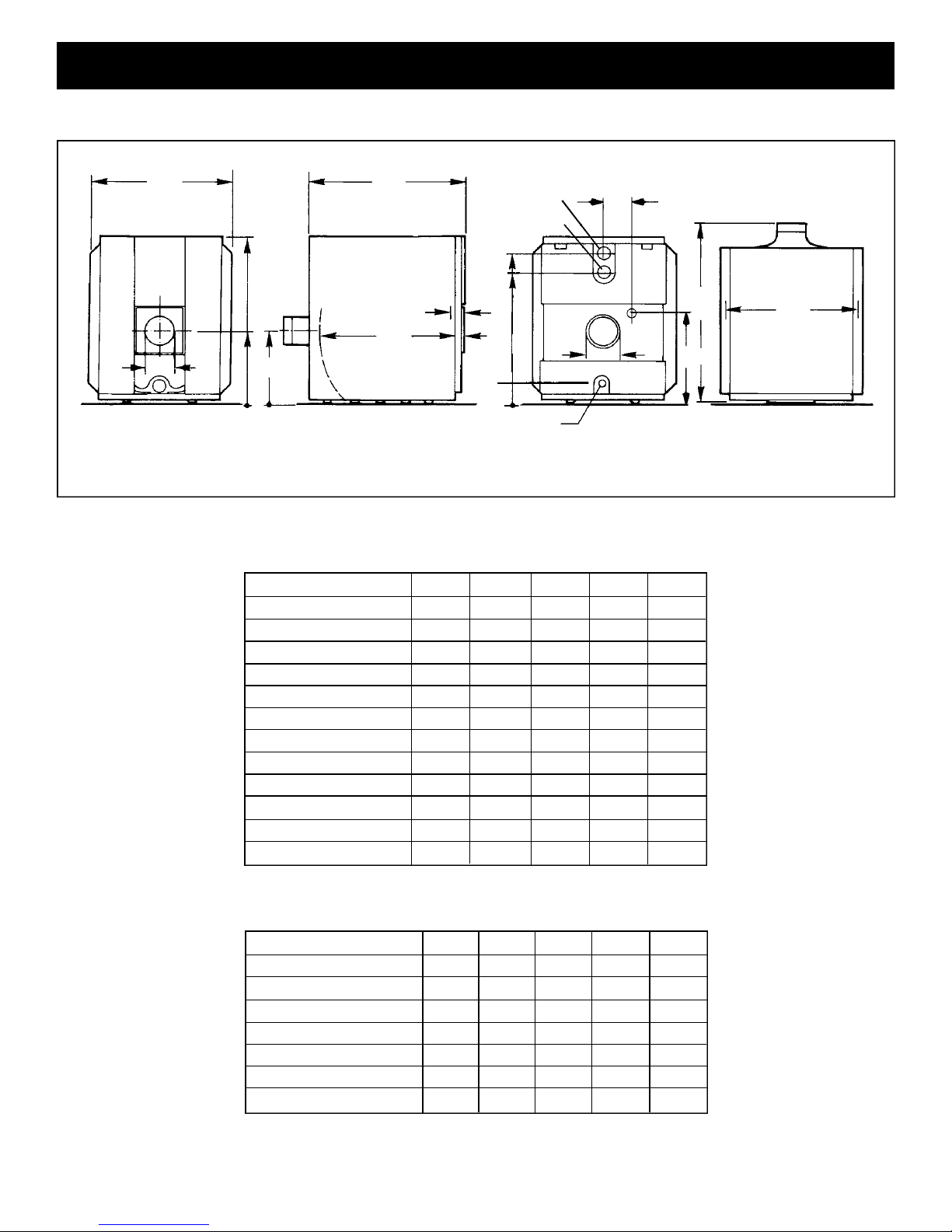
Fig. 1
34
max.
3/4
”
3/4
40
”
3/4
17
”
3/4
17
9”
”
L
K
Supply
1/4
11
”
Return
37”
1/4
32
”
T
L
F
3/4”
Drain
Side ViewFront View
Rear View
1”
7”
L
G
1/2
25
”
B
E
Top View
Table 1: Boiler Dimensions
Gross Output (Btu/hr.) 358,000 478,000 580,000 682,000 785,000
No. of Sections 5 6 7 8 9
Overall Boiler Length LG(In.) 44
Boiler Block Length LK(In.) 38
1
/4 501/2 563/4 631/4 691/2
1
/4 441/2 503/4 57 631/2
Minimum Boiler Width BE(In.) 28 28 28 28 28
Fire Box Depth L
(In.) 31 37
F
Fire Box Diameter (In.) 15
3
/4 153/4 153/4 153/4 153/4
1
/2 433/4 50 561/4
Fire Box Volume (Cu.Ft.) 5.19 6.39 7.59 8.79 9.99
Dry Weight (Lbs.) 1197 1391 1585 1779 1973
Water Content (Gals.) 37.8 45.2 52.6 60.0 67.4
Operating Weight (Lbs.) 1512 1768 2024 2280 2535
Vent Connection Size (In.) 7 7 7 7 7
Door Thickness T (In.) 5 5 5 5 5
Table 2: Technical Specifications
Gross Output (Btu/hr.) 358,000 478,000 580,000 682,000 785,000
No. of Sections 5 6 7 8 9
Boiler HP 10.7 14.3 17.4 20.4 23.5
Net IBR Rating (Btu/hr.) 311,000 416,000 504,000 593,000 683,000
Max Input Oil (GPH) 3.0 3.85 4.7 5.5 6.4
Max Input Gas (Btu/hr.) 420,000 540,000 660,000 770,000 896,000
Fire side heating surface (Sq.ft.) 50.6 62.4 74.3 86.1 96.9
Firebox Pressure (In. W.C.) .18 .32 .50 .71 .75
5
4 Boiler Foundation and Minimum Boiler Clearances
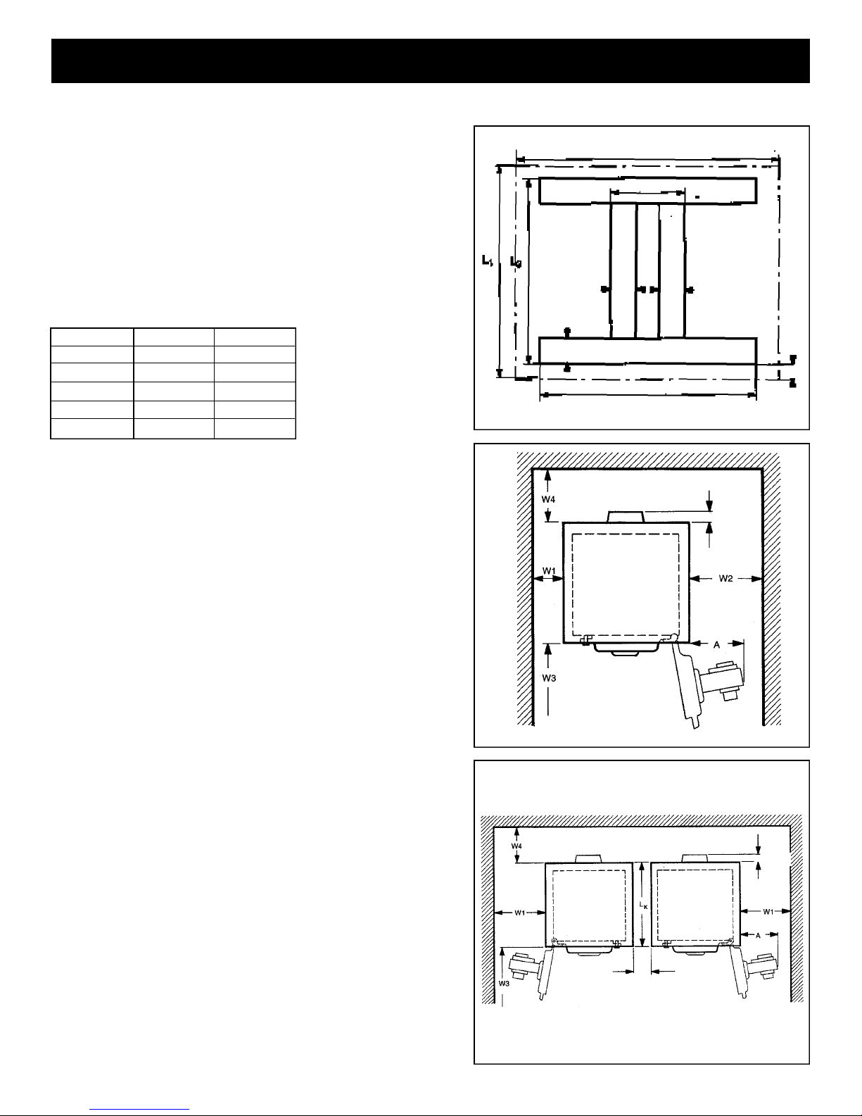
Boiler foundation preparations
It is required that the boiler is placed on a level, smooth
concrete base, of sufficient strength. The width of the
platform must be 33 1/2”. Length L1is the platform
length. It is required to cement in either a 4” x 1/4” flat
steel plate or a 4” x 2” x 1/4” angle iron, as shown in
Figure 2; Table 3 shows dimensions.
T able 3: Foundation and support strip lengths
No. of Sections Length LI (In.) Length L2 (In.)
5 36 28
6 42
7 48
8 54
9 61 54
1
/4 35
1
/2 411/4
3
/4 471/2
3
/4
Minimum wall clearances
The recommended wall clearances must be observed in
order to open the burner door, assemble the boiler and
allow sufficient access for boiler maintenance.
(See Figures 3 and 4 for details).
Fig. 2
1 / 2
33
”
10”
4 ”
4 ”
20”
4 ”
1 / 2
3
”
3 / 4
7
”
The burner door is field adjustable to hinge right or left.
Recommended clearances:
Wall clearance W1: minimum 12”.
Wall clearance W2: Burner length A + 4”, minimum 43”.
Wall clearance W3: Boiler length L + 40”.
Wall clearance W4: 1/2 Boiler length + 20”.
Absolute minimum clearances:
Wall clearance W1: minimum 12”.
Wall clearance W2:* minimum 12”.
Wall clearance W3: Boiler length L or minimum 86”.
Wall clearance W4: 36”.
Note: Wall clearance W3 can be reduced to 4 feet for
assembled boilers. Boiler cleaning will now require
use of segmented brushes.
*Requires burner removal during cleaning.
6
Fig. 3
Fig. 4
16”
3 / 4
7
”
Assembly Tools/Tools Req’d for Boiler Assembly 5
Assembly tools and auxiliary assembly materials
✔ Boiler assembly tool rods size 2.2 (2 pieces)
✔ Wooden or rubber mallet
✔ Half-round rough file
✔ Flat head and Phillips screwdrivers
✔ Flat chisel, steel strips for boiler support
✔ Metric wrenches sizes 13, 19, 24, 36 and socket
✔ size 19 (US equivalent sizes may also be used)
✔ Cleaning rags, machine oil, gasoline or paint
thinner, level, steel wire brush, tape measure,
chalk.
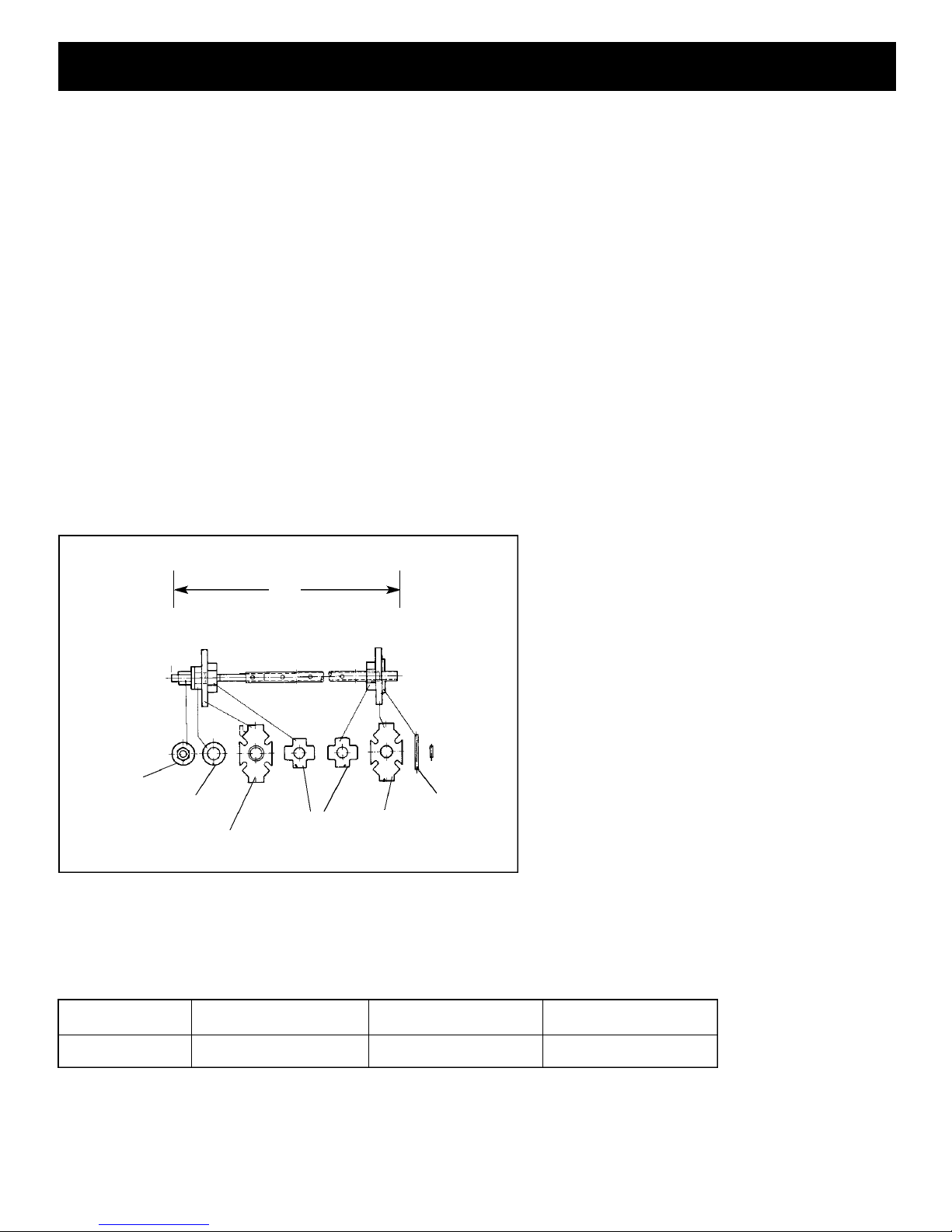
Boiler assembly tool components
Tightening Nut
Pressure
Bearing
Pressure
Fig. 5
Table 4. Assembly tool requirements
Bearing
Assembly Tool
85”
Small
Pressure
Flanges
Straight Pin
Stop
Flange
No. of Sections Assembly Tool Extension Piece Total Tool Length (ft)
5-9 1 0 7
7
6 Boiler Assembly
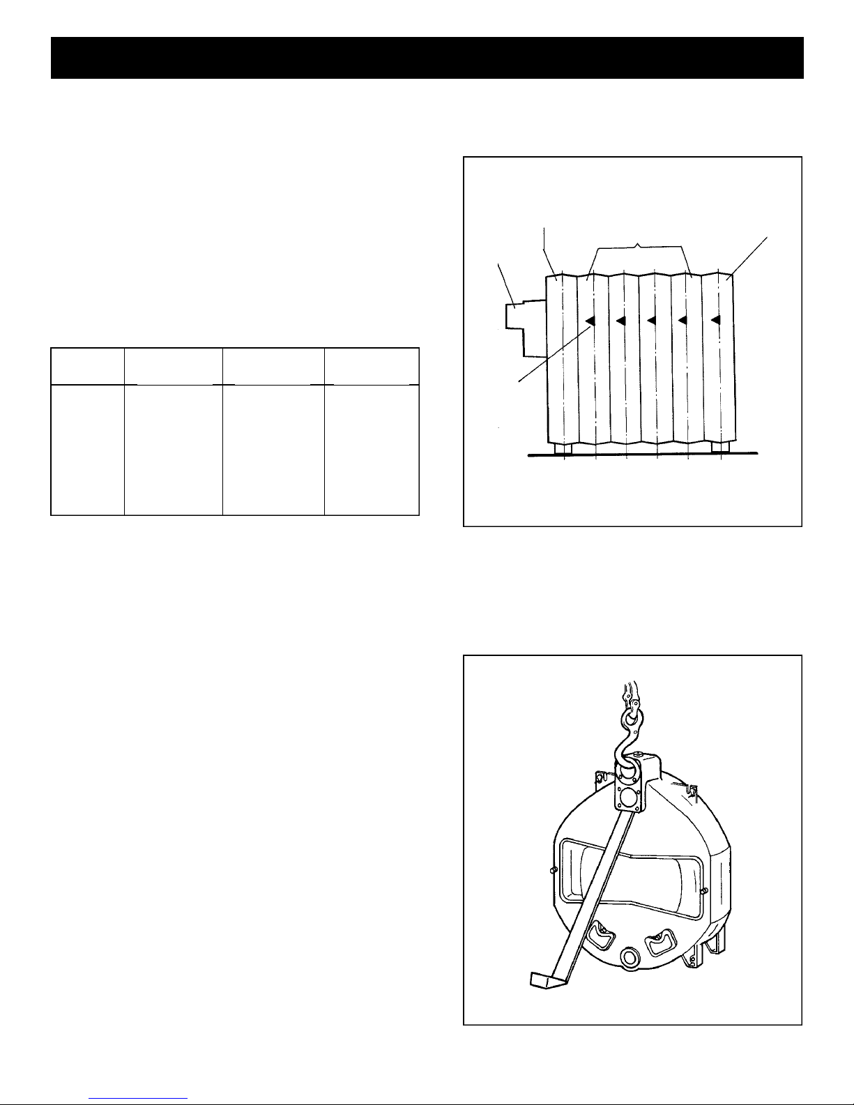
Boiler block sectional arrangement
The boiler is always assembled starting with the rear section
and finishing with the front section.
The arrow markings on the sections must point to the rear
(Fig. 6) and use the sequence in Table 5.
Table 5: Boiler section arrangement
Model
315/5 1 3 1
315/6 1 4 1
315/7 1 5 1
315/8 1 6 1
315/9 1 7 1
Front Section
No. of
No. of
Midsections
No. of
Rear Section
Flue gas
collector
Assembly
arrow marking
Fig. 6
Rear
section
Middle sections
Front
section
Assembly of individual boiler sections
• Remove the nuts and washers from the rear and
front sections prior to boiler assembly.
• Note the arrow marking on each section. These
arrows are located on the top left and right of
each section and must point to the rear during
boiler assembly (Fig. 6).
• Assemble the boiler on a smooth hard surface
with flat steel plates underneath to permit easy
sliding of sections.
• Position and align the rear section upright in
final location and secure it from falling over
(Fig. 7).
• To reduce the risk of injuries, support the boiler
section or secure it with an overhead lifting device.
8
Fig. 7
 Loading...