

Page 1
EM100
1
2
3
4
5
6
7
8
9
10
0
de Installationsanleitung für das Fachhandwerk.. . . . . . . . . . . . . . . . . . . . . . . . . . . . . . . . . . . . . . . . . . . . . . 2
en Installation instructions for skilled labour . . . . . . . . . . . . . . . . . . . . . . . . . . . . . . . . . . . . . . . . . . . . . . . 11
fl Installatiehandleiding voor de installateur. . . . . . . . . . . . . . . . . . . . . . . . . . . . . . . . . . . . . . . . . . . . . . . 20
fr Notice d’installation pour le professionnel . . . . . . . . . . . . . . . . . . . . . . . . . . . . . . . . . . . . . . . . . . . . . . 29
it Istruzioni per l'installazione per tecnico specializzato . . . . . . . . . . . . . . . . . . . . . . . . . . . . . . . . . . . . . 39
EMS
EMS plus
5
6
4
7
3
8
2
9
1
100
6720891034 (2019/04) DE/BE/GB/FR/IT
Page 2
Inhaltsverzeichnis
Inhaltsverzeichnis 1 Symbolerklärung und
Sicherheitshinweise
1 Symbolerklärung und Sicherheitshinweise. . . . . . . . . 2
1.1 Symbolerklärung . . . . . . . . . . . . . . . . . . . . . . . . . . . 2
1.2 Allgemeine Sicherheitshinweise . . . . . . . . . . . . . . . 3
2 Angaben zum Produkt. . . . . . . . . . . . . . . . . . . . . . . . . . . 4
2.1 Wichtige Hinweise zur Verwendung . . . . . . . . . . . . 4
2.2 Regelung des Wärmeerzeugers. . . . . . . . . . . . . . . . 4
2.2.1 Leistungsregelung . . . . . . . . . . . . . . . . . . . . . . . . . . 4
2.2.2 Vorlauftemperaturregelung. . . . . . . . . . . . . . . . . . . 5
2.3 Lieferumfang . . . . . . . . . . . . . . . . . . . . . . . . . . . . . . 5
2.4 Technische Daten. . . . . . . . . . . . . . . . . . . . . . . . . . . 5
2.5 Ergänzendes Zubehör . . . . . . . . . . . . . . . . . . . . . . . 5
2.6 Reinigung . . . . . . . . . . . . . . . . . . . . . . . . . . . . . . . . . 5
3 Installation . . . . . . . . . . . . . . . . . . . . . . . . . . . . . . . . . . . . 6
3.1 Vorbereitung für die Installation im
Wärmeerzeuger . . . . . . . . . . . . . . . . . . . . . . . . . . . . 6
3.2 Installationsorte. . . . . . . . . . . . . . . . . . . . . . . . . . . . 6
3.3 Installation eines Temperaturfühlers an der
hydraulischen Weiche oder hinter dem
Wärmetauscher . . . . . . . . . . . . . . . . . . . . . . . . . . . . 6
3.4 Elektrischer Anschluss . . . . . . . . . . . . . . . . . . . . . . 7
3.4.1 Anschluss BUS-Verbindung und
Temperaturfühler (Kleinspannungsseite). . . . . . . . 7
3.4.2 Anschluss Spannungsversorgung, Pumpe,
Magnetventil oder Störmeldung
(Netzspannungsseite) . . . . . . . . . . . . . . . . . . . . . . . 7
3.4.3 Überblick Anschlussklemmenbelegung . . . . . . . . . 8
4 Inbetriebnahme . . . . . . . . . . . . . . . . . . . . . . . . . . . . . . . . 9
4.1 Kodierschalter einstellen. . . . . . . . . . . . . . . . . . . . . 9
4.2 Inbetriebnahme der Anlage und des Moduls . . . . . 9
4.3 Menü Einstellungen EM100 . . . . . . . . . . . . . . . . . . 9
1.1 Symbolerklärung
Warnhinweise
In Warnhinweisen kennzeichnen Signalwörter die Art und
Schwere der Folgen, falls die Maßnahmen zur Abwendung der
Gefahr nicht befolgt werden.
Folgende Signalwörter sind definiert und können im vorliegenden Dokument verwendet sein:
GEFAHR:
GEFAHR bedeutet, dass schwere bis lebensgefährliche
Personenschäden auftreten werden.
WARNUNG:
WARNUNG bedeutet, dass schwere bis lebensgefährliche Per-
sonenschäden auftreten können.
VORSICHT:
VORSICHT bedeutet, dass leichte bis mittelschwere Personen-
schäden auftreten können.
HINWEIS:
HINWEIS bedeutet, dass Sachschäden auftreten können.
Wichtige Informationen
Wichtige Informationen ohne Gefahren für Menschen oder Sachen werden mit dem gezeigten Info-Symbol gekennzeichnet.
5 Störungen beheben . . . . . . . . . . . . . . . . . . . . . . . . . . . . 10
6 Umweltschutz/Entsorgung. . . . . . . . . . . . . . . . . . . . . . 10
2
Weitere Symbole
Symbol Bedeutung
▶ Handlungsschritt
Querverweis auf eine andere Stelle im Dokument
• Aufzählung/Listeneintrag
– Aufzählung/Listeneintrag (2. Ebene)
Tab. 1
EM100 – 6720891034 (2019/04)
Page 3

1 Symbolerklärung und Sicherheitshinweise
1.2 Allgemeine Sicherheitshinweise
H Hinweise für die Zielgruppe
Diese Installationsanleitung richtet sich
an Fachkräfte für Gas- und Wasserinstallationen, Heizungs- und Elektrotechnik.
Die Anweisungen in allen Anleitungen
müssen eingehalten werden. Bei Nichtbeachten können Sachschäden und Personenschäden bis hin zur Lebensgefahr
entstehen.
▶ Installationsanleitungen (Wärmeer-
zeuger, Heizungsregler usw.) vor der
Installation lesen.
▶ Sicherheits- und Warnhinweise
beachten.
▶ Nationale und regionale Vorschriften,
technische Regeln und Richtlinien
beachten.
▶ Ausgeführte Arbeiten dokumentieren.
H
Bestimmungsgemäße Verwendung
▶ Produkt ausschließlich zur Regelung
von Heizungsanlagen verwenden.
Jede andere Verwendung ist nicht bestimmungsgemäß. Daraus resultierende
Schäden sind von der Haftung ausgeschlossen.
H Installation, Inbetriebnahme und
Wartung
Installation, Inbetriebnahme und Wartung
darf nur ein zugelassener Fachbetrieb
ausführen.
▶ Produkt nicht in Feuchträumen
installieren.
▶ Nur Originalersatzteile einbauen.
H Elektroarbeiten
Elektroarbeiten dürfen nur Fachleute für
Elektroinstallationen ausführen.
▶ Vor Elektroarbeiten:
– Netzspannung (allpolig) span-
nungsfrei schalten und gegen
Wiedereinschalten sichern.
– Spannungsfreiheit feststellen.
▶ Produkt benötigt unterschiedliche
Spannungen.
Kleinspannungsseite nicht an
Netzspannung anschließen und umgekehrt.
▶ Anschlusspläne weiterer Anlagenteile
ebenfalls beachten.
H Übergabe an den Betreiber
Weisen Sie den Betreiber bei der
Übergabe in die Bedienung und die
Betriebsbedingungen der Heizungsanlage ein.
▶ Bedienung erklären – dabei beson-
ders auf alle sicherheitsrelevanten
Handlungen eingehen.
▶ Darauf hinweisen, dass Umbau oder
Instandsetzungen nur von einem zugelassenen Fachbetrieb ausgeführt
werden dürfen.
▶ Auf die Notwendigkeit von Inspektion
und Wartung für den sicheren und umweltverträglichen Betrieb hinweisen.
▶ Installations- und Bedienungsanlei-
tungen zur Aufbewahrung an den
Betreiber übergeben.
EM100 – 6720891034 (2019/04)
3
Page 4
2
Angaben zum Produkt
H Schäden durch Frost
Wenn die Anlage nicht in Betrieb ist,
kann sie einfrieren:
▶ Hinweise zum Frostschutz beachten.
▶ Anlage immer eingeschaltet lassen,
wegen zusätzlicher Funktionen,
z. B. Warmwasserbereitung oder
Blockierschutz.
▶ Auftretende Störungen umgehend be-
seitigen lassen.
2 Angaben zum Produkt
• Das Modul kann über ein externes Steuersignal mit 0-10 V
(Gleichspannung) die Kessel-Vorlauftemperatur oder die
Leistung des Heizkessels anpassen.
• Das Modul meldet Störungen des Heizkessels sowie Anlagenstörungen, mit Ausnahme von Serviceanzeigen, Störungen externer Regler oder Wartung für den Installateur.
• Das Modul kann der Ansteuerung eines zweiten Magnetventils dienen und für Heizkessel in Flüssiggasausführung eingesetzt werden.
• Das Modul dient als Erweiterungsmodul für EMS- und
EMS plus-Kessel.
• Das Modul dient der modulierenden Drehzahlregelung
„Flow Control“ einer Kesselkreispumpe (0-10 V oder PWM)
in Verbindung mit hydraulischer Weiche oder Wärmetauscher.
Die Kesselkreispumpe passt den kesselseitigen Volumenstrom an und verhindert eine Rücklauftemperaturanhebung des Kessels. Ziel ist ein optimierter Brennwertnutzen
sowie Stromeinsparung. Durch die Auswahl 0-10V- oder
PWM-Signal ist die Funktion geeignet bei bodenstehenden
Kesseln und Wandgeräten GB162 >45 kW mit werkseitiger
Pumpengruppe.
3 Regelungsarten sind auswählbar:
1. Vorlauftemperaturregelung: Differenz Kesselvorlauf zu Anlagenvorlauf
2. Leistungsregelung: parallel zur Kesselleistung (wenn kein
Zusatzfühler möglich)
3. Differenz Kesselvorlauf zu Kesselrücklauf (empfohlen für
Wärmetauscher)
Die Kombinationsmöglichkeiten der Module sind aus den Anschlussplänen ersichtlich.
(empfohlen für hydraulische Weiche)
2.1 Wichtige Hinweise zur Verwendung
• Der Funktionsumfang ist von der installierten Bedieneinheit abhängig. Genaue Angaben zu Bedieneinheiten entnehmen Sie bitte dem Katalog, den Planungsunterlagen
und der Webseite des Herstellers.
• Der Installationsraum muss für die Schutzart gemäß den
technischen Daten des Moduls geeignet sein.
2.2 Regelung des Wärmeerzeugers
Diese Regelungsstrategie findet Anwendung, wenn die Heizungsanlage über eine Gebäudeleittechnik mit einem 0-10VReglerausgang geregelt wird ( Bild 22 am Dokumentende).
Eingangsspannung
0 V - 0,5 V 0 %/0 °C aus
0,6 V ca. 6 %/ca. 15 °C ein, wenn > min. Leistung
5,0 V ca. 50 %/ca. 50 °C ein
10,0 V ca. 100 %/ca. 90 °C ein/Maximum
Tab. 2 Regelung nach Leistung/Vorlauftemperatur
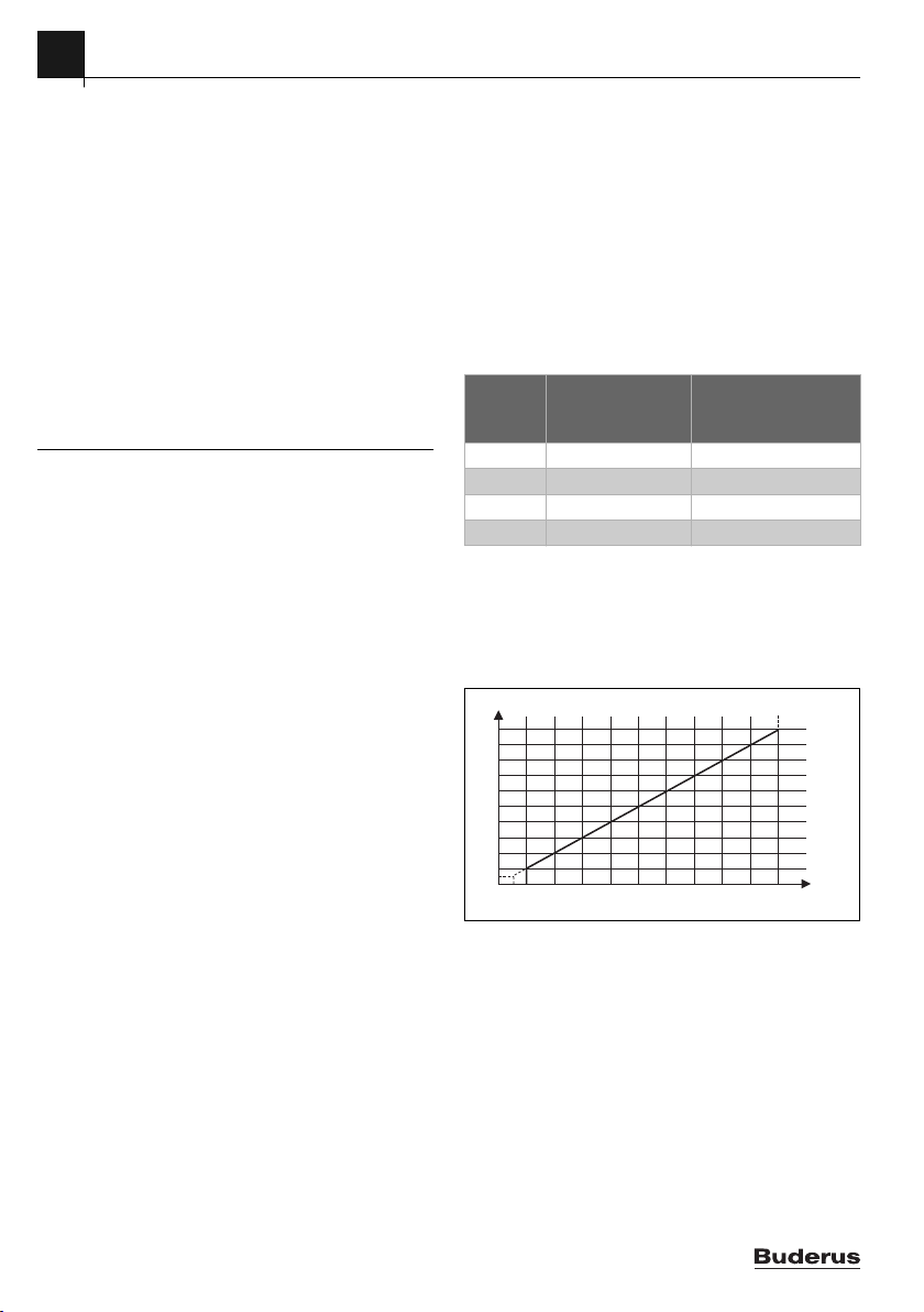
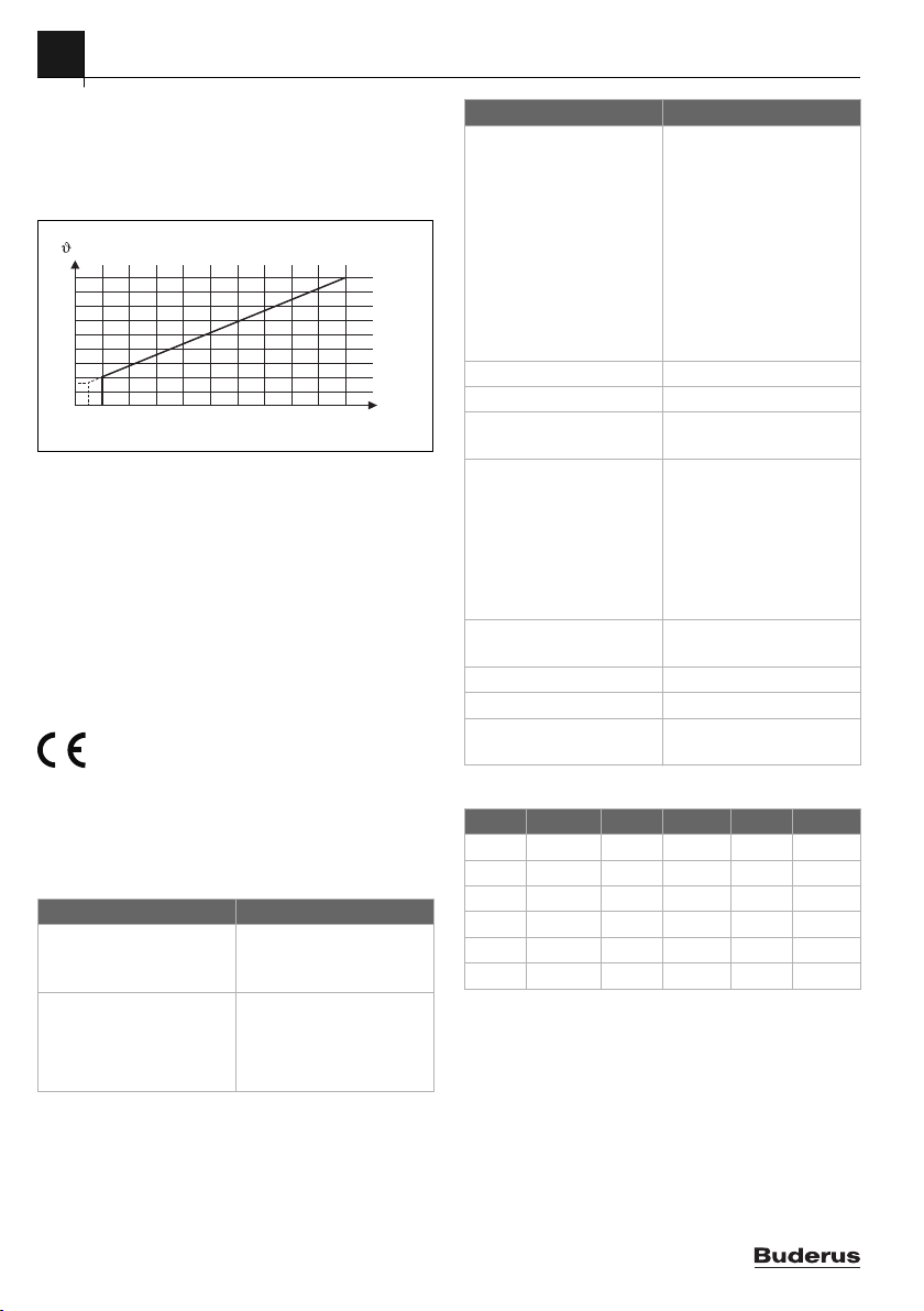
2.2.1 Leistungsregelung
Linearer Zusammenhang zwischen 0-10V-Signal (U in V) und
angeforderter Leistung (P in % bezogen auf die maximale
Leistung der Anlage):
P / %
100
10
Bild 1 Linearer Zusammenhang zwischen 0-10 V-Signal
Die angeschlossenen Wärmeerzeuger werden entsprechend
der angeforderten Leistung zu- und abgeschaltet.
Vorlauftemperatur/
Leistung Sollwert
(Heizkessel)
0,5
110
(U in V) und angeforderter Leistung (P in %)
Status Heizkessel
U / V
0010013227-002
4
EM100 – 6720891034 (2019/04)
Page 5
2 Angaben zum Produkt
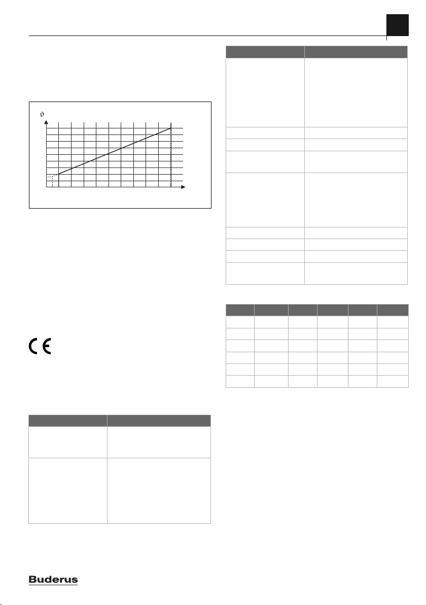
2.2.2 Vorlauftemperaturregelung
Linearer Zusammenhang zwischen 0-10V-Signal (U in V) und
angeforderter Vorlauftemperatur in °C bezogen auf den Be-
reich minimale Vorlauftemperatur bis maximale Vorlauftemperatur [Grundeinstellung 20 bis 90 °C]):
/ °C
90
20
0,5
110
U / V
0010024409-001
Bild 2 Linearer Zusammenhang zwischen 0-10V-Signal
(U in V) und angeforderter Vorlauftemperatur in °C)
Die angeschlossenen Wärmeerzeuger werden entsprechend
der angeforderten Vorlauftemperatur zu- und abgeschaltet.
2.3 Lieferumfang
Bild 6 am Dokumentende:
[1] Modul
[2] Beutel mit Zugentlastungen
[3] Installationsanleitung
2.4 Technische Daten
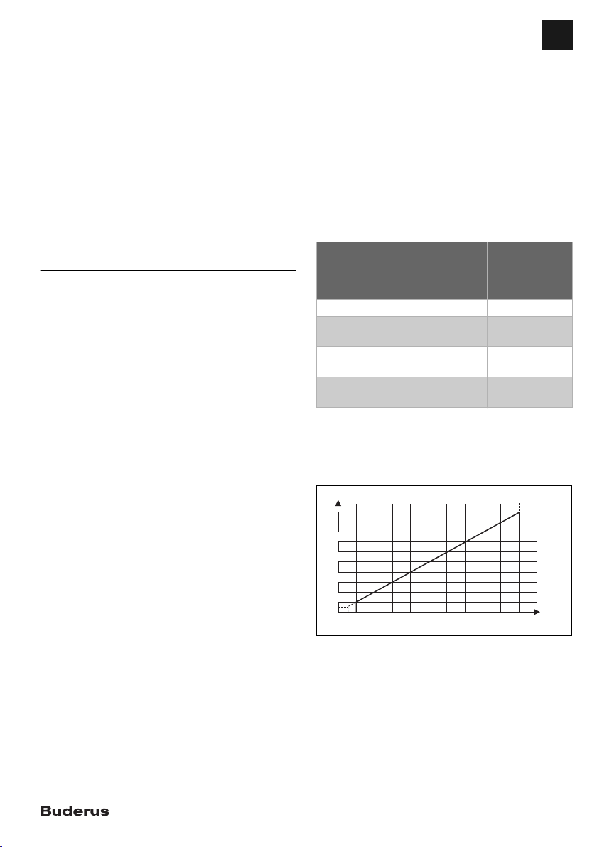
Dieses Produkt entspricht in Konstruktion und Betriebsverhalten den europäischen Richtlinien sowie
Konformität wurde mit der CE-Kennzeichnung nachgewiesen.
Sie können die Konformitätserklärung des Produkts anfordern.
Wenden Sie sich dazu an die Adresse auf der Rückseite dieser
Anleitung.
den ergänzenden nationalen Anforderungen. Die
Technische Daten
Abmessungen
(B × H × T)
151 × 184 × 61 mm
(weitere Maße Bild 7 am
Dokumentende)
Maximaler Leiterquerschnitt
• Anschlussklemme
• 2,5 mm
230 V
• Anschlussklemme
• 1,5 mm
Kleinspannung
2
2
Technische Daten
Nennspannungen
• BUS • 15 V DC (verpolungssicher)
• Netzspannung Modul • 230 V AC, 50 Hz
• Bedieneinheit • 15 V DC (verpolungssicher)
• Pumpe, Magnetven-
• 230 V AC, 50 Hz
til, Störausgang
Sicherung 230 V, 5 AT
BUS-Schnittstelle EMS und EMS plus
Leistungsaufnahme –
< 3 W
Standby
max. Leistungsabgabe
• pro Anschluss (PC0)
• 400 W (Hocheffizienzpumpen
zulässig: < 30 A für 10 ms)
• 120 W (Hocheffizienzpumpen
• pro Anschluss (OE1)
zulässig: < 30 A für 10 ms)
zul. Umgebungstemp. 0 ... 60 °C
Schutzart IP 44
Schutzklasse I
Ident.-Nr. Typschild ( Bild 21 am
Dokumentende)
Tab. 3
°C °C °C
20 12486 50 3605 80 1256
25 10000 55 2989 85 1070
30 8060 60 2490 90 915
35 6536 65 2084 100 677
40 5331 70 1753 – –
45 4372 75 1480 – –
Tab. 4 Messwerte Weichentemperaturfühler (T0)
2.5 Ergänzendes Zubehör
Genaue Angaben zu geeignetem Zubehör entnehmen Sie bitte
dem Katalog oder der Internetseite des Herstellers.
• Weichentemperaturfühler; Anschluss an T0
• Primärkreispumpe; Anschluss an PC0
Installation des ergänzenden Zubehörs
▶ Ergänzendes Zubehör entsprechend den gesetzlichen Vor-
schriften und der mitgelieferten Anleitungen installieren.
2.6 Reinigung
▶ Bei Bedarf mit einem feuchten Tuch das Gehäuse abreiben.
Dabei keine scharfen oder ätzenden Reinigungsmittel verwenden.
EM100 – 6720891034 (2019/04)
5
Page 6
3
Installation
3 Installation
GEFAHR:
Lebensgefahr durch elektrischen Strom!
Das Berühren von elektrischen Teilen, die unter Spannung stehen, kann zum Stromschlag führen.
▶ Vor Installation dieses Produktes: Wärmeerzeuger und
alle weiteren BUS-Teilnehmer allpolig von der
Netzspannung trennen.
▶ Vor Inbetriebnahme: Abdeckung anbringen
( Bild 20 am Dokumentende).
3.1 Vorbereitung für die Installation im Wärmeerzeuger
▶ Über die Installationsanleitung des Wärmeerzeugers überprü-
fen, ob dieser die Möglichkeit bietet, Module (z. B. EM100)
im Wärmeerzeuger zu installieren.
▶ Wenn das Modul ohne Hutschiene im Wärmeerzeuger
installiert werden kann, Modul vorbereiten ( Bild 8 und 9
am Dokumentende).
3.2 Installationsorte
▶ Modul an einer Wand ( Bild
an einer Hutschiene ( Bild
Baugruppe oder im Wärmeerzeuger installieren.
▶ Bei der Installation des Moduls in einem Wärmeerzeuger,
die Anleitung des Wärmeerzeugers beachten.
▶ Modul von der Hutschiene entfernen
( Bild 13 am Dokumentende).
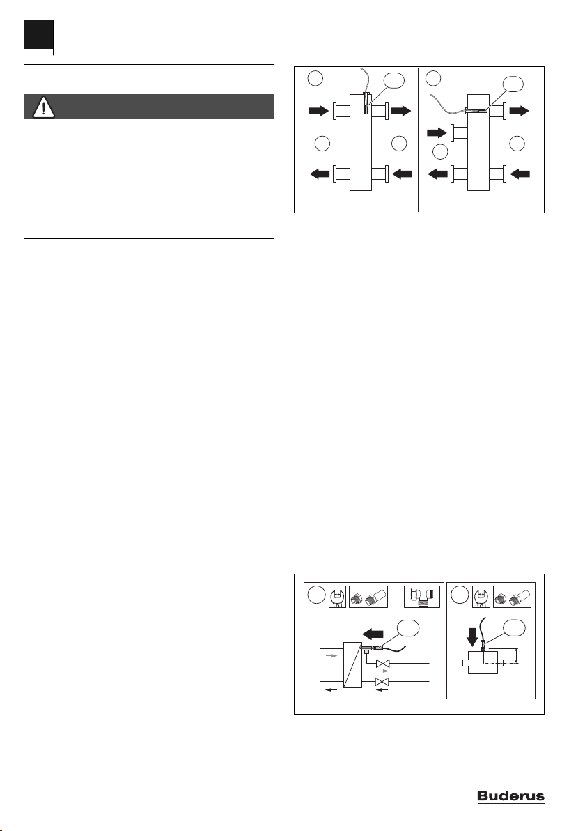
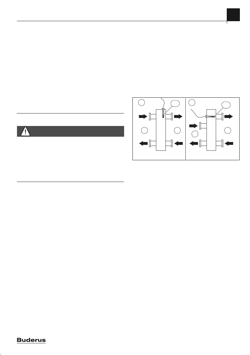
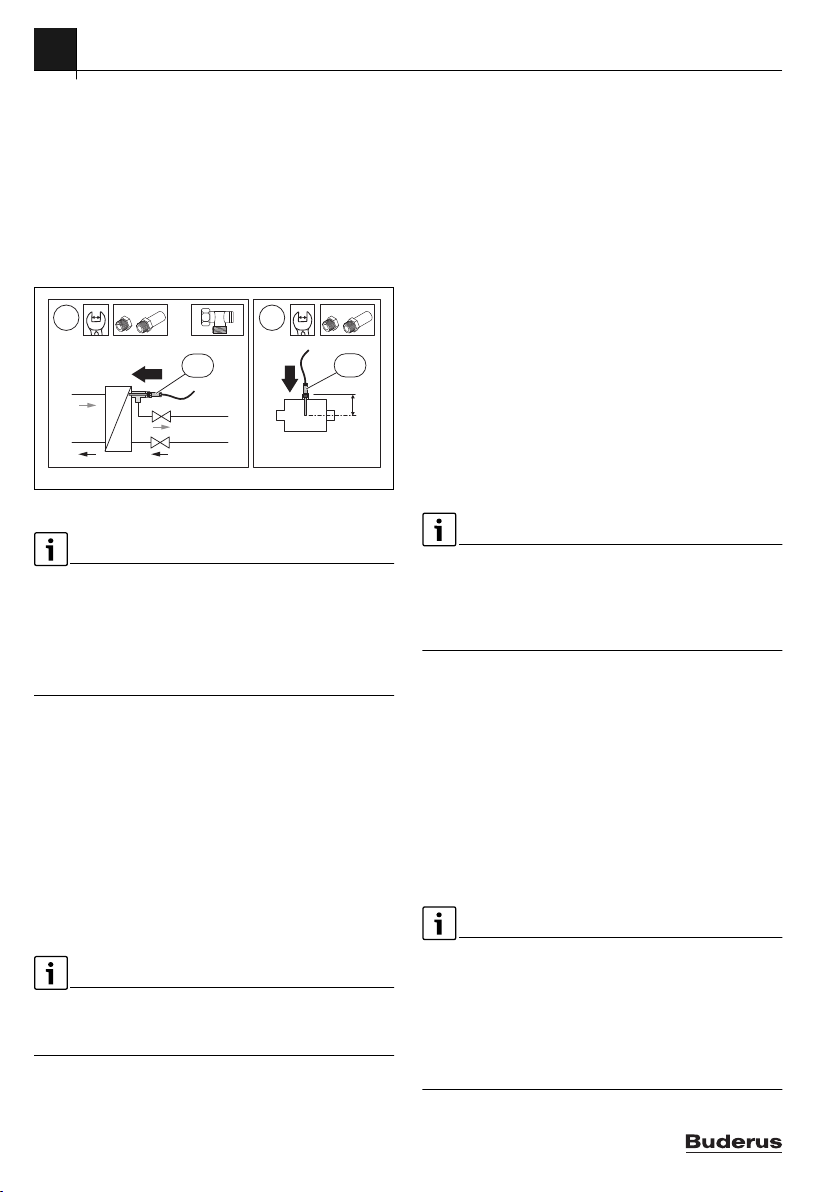
3.3 Installation eines Temperaturfühlers an der
hydraulischen Weiche oder hinter dem Wärmetauscher
Der Weichentemperaturfühler T0 sollte vorrangig mit EM100
verbunden sein. Bei Heizgeräten mit EMS plus kann der Fühler
auch am Gerät oder einem MM100 angeschlossen werden.
Installation an der hydraulischen Weiche
( Bild 23 und 25 am Dokumentende)
Position Temperaturfühler Vorlauf (T0):
10
und
11
12
am Dokumentende),
am Dokumentende), in einer
A
ϑ
1
T0
12
ϑ
2
B
ϑ
3
ϑ
1
1
ϑ
ϑ
4
2
T0
ϑ
2
ϑ
4
0 010 013 230-001
3
Bild 3 Position Temperaturfühler Vorlauf (T0)
[1] alle Wärmeerzeuger
[2] alle Heizkreise
A hydraulische Weiche Bauform 1
B hydraulische Weiche Bauform 2
1gemeinsame Vorlauftemperatur aller Wärmeerzeuger
gemeinsame Rücklauftemperatur aller Wärmeerzeuger
2
gemeinsame Vorlauftemperatur aller Heizkreise
3
gemeinsame Rücklauftemperatur aller Heizkreise
4
T0 Temperaturfühler Vorlauf an der hydraulischen Weiche
T0 ist so zu positionieren, dass
strom auf der Seite aller Wärmeerzeuger [1] erfasst wird. Nur
unabhängig vom Volumen-
3
so kann die Regelung auch bei kleinen Lasten stabil arbeiten.
Für ein optimales Regelverhalten sollte der Temperaturfühler
umströmt werden. Dies kann durch Kombination von T-Stück,
Hahnverlängerung und Fühlerset erreicht werden.
Optimierte Fühlermontage hinter dem Wärmetauscher
Der Temperaturfühler (T0) muss am Vorlauf nach dem
Wärmetauscher sekundärseitig (Nassfühler) angebracht
werden ( Bild 24 am Dokumentende).
Für eine optimierte Fühlermontage hinter dem Wärmetauscher
gibt es zwei Möglichkeiten ( Position [1] mit Eck-Verschraubung und Position [2], Bild 4 "Optimierte Fühlermontage"):
24
B
A
1
T0
24
B
A
2
T0
0010024454-001
Bild 4 Optimierte Fühlermontage
6
EM100 – 6720891034 (2019/04)
Page 7

Der Temperaturfühler muss mittig im Rohr messen.
▶ Die Einbautiefe des Weichen-Temperaturfühlers mit Hahn-
verlängerungen anpassen ( Installationsanleitung Fühlerset hydraulische Weiche). Bei ordnungsgemäßer Montage
ragt der Fühler 1-2 cm in den Wärmetauscher hinein.
3.4 Elektrischer Anschluss
▶ Unter Berücksichtigung der geltenden Vorschriften für den
Anschluss mindestens Elektrokabel der Bauart H05 VV-...
verwenden.
3.4.1 Anschluss BUS-Verbindung und Temperaturfühler
(Kleinspannungsseite)
▶ Bei unterschiedlichen Leiterquerschnitten Verteilerdose
für den Anschluss der BUS-Teilnehmer verwenden.
▶ BUS-Teilnehmer [B] über Verteilerdose [A] in Stern
( Bild 18 am Dokumentende) oder über BUS-Teilnehmer
mit 2 BUS-Anschlüssen in Reihe schalten.
3 Installation
3.4.2 Anschluss Spannungsversorgung, Pumpe, Magnetventil oder Störmeldung (Netzspannungsseite)
Die Belegung der elektrischen Anschlüsse ist von der installierten Anlage abhängig. Die am Dokumentende in Bild 14 bis 17
dargestellte Beschreibung ist ein Vorschlag für den Ablauf des
elektrischen Anschlusses. Die Handlungsschritte sind teilweise
nicht schwarz dargestellt. Damit ist leichter zu erkennen, welche Handlungsschritte zusammengehören.
▶ Nur Elektrokabel gleicher Qualität verwenden.
▶ Auf phasenrichtige Installation des Netzanschlusses achten.
Netzanschluss über einen Schutzkontaktstecker ist nicht
zulässig.
▶ An den Ausgängen nur Bauteile und Baugruppen gemäß
dieser Anleitung anschließen. Keine zusätzlichen Steuerungen anschließen, die weitere Anlagenteile steuern.
▶ Kabel durch die Tüllen führen, gemäß den Anschlussplänen
anklemmen und mit den im Lieferumfang enthaltenen Zugentlastungen sichern ( Bild
14
bis
17
am Dokumentende).
Wenn die maximale Gesamtlänge der BUS-Verbindungen zwischen allen BUS-Teilnehmern überschritten wird oder im BUSSystem eine Ringstruktur vorliegt, ist die Inbetriebnahme der
Anlage nicht möglich.
Maximale Gesamtlänge der BUS-Verbindungen:
2
• 100 m mit 0,50 mm
• 300 m mit 1,50 mm
Leiterquerschnitt
2
Leiterquerschnitt
▶ Um induktive Beeinflussungen zu vermeiden: Alle Klein-
spannungskabel von Netzspannung führenden Kabeln getrennt verlegen (Mindestabstand 100 mm).
▶ Bei induktiven äußeren Einflüssen (z. B. von PV-Anlagen)
Kabel geschirmt ausführen (z. B. LiYCY) und Schirmung
einseitig erden. Schirmung nicht an Anschlussklemme für
Schutzleiter im Modul anschließen, sondern an Hauserdung, z. B. freie Schutzleiterklemme oder Wasserrohre.
Bei Verlängerung der Fühlerleitung folgende Leiterquerschnitte
verwenden:
• Bis 20 m mit 0,75 bis 1,50 mm
• 20 bis 100 m mit 1,50 mm
2
Leiterquerschnitt
2
Leiterquerschnitt
▶ Kabel durch die bereits vormontierten Tüllen führen und ge-
mäß den Anschlussplänen anklemmen.
EM100 – 6720891034 (2019/04)
Die maximale Leistungsaufnahme der angeschlossenen Bauteile und Baugruppen darf die in den technischen Daten des Moduls angegebene Leistungsabgabe nicht überschreiten.
▶ Wenn die Netzspannungsversorgung nicht über die Elektro-
nik des Wärmeerzeugers erfolgt, bauseits zur Unterbrechung der Netzspannungsversorgung eine allpolige
normgerechte Trennvorrichtung (nach EN 60335-1) installieren.
7
Page 8
3
0
1
2
3
4
5
6
7
8
9
10
0
1
2
3
4
5
6
7
8
9
10
Installation
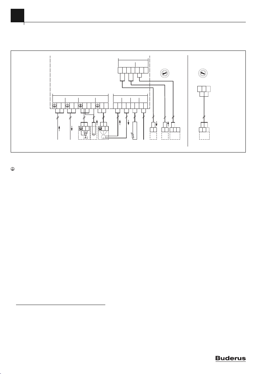
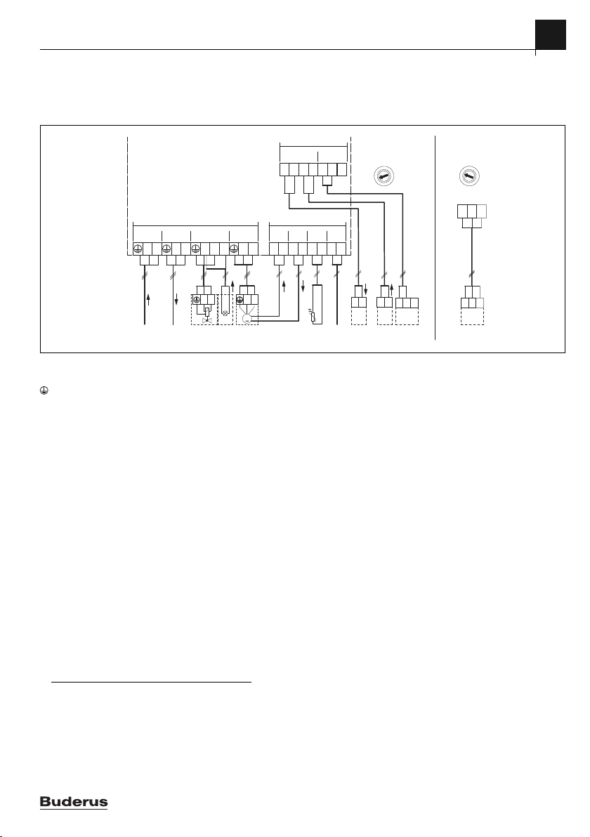
3.4.3 Überblick Anschlussklemmenbelegung
Dieser Überblick zeigt, welche Anlagenteile angeschlossen
werden können.
EM100
120/230 V AC
230 VAC
OE1 PC0
N
L
OE1 OE1
120/230VAC120/230VAC
NL N N74 N6375L
230 VAC
Legende zum Bild oben und zu den Anschlussplänen mit
Anlagenbeispielen am Dokumentende:
Schutzleiter
Anschlussklemmenbezeichnungen:
230 V AC Anschluss Netzspannung
BUS Anschluss BUS-System
BMS Gebäudeleittechnik (Building Management System)
mit 0-10V-Schnittstelle
HS Wärmeerzeuger (Heat Source) an BUS-System
OE1-74 Ausgang Netzspannung Magnetventil
OE1-75 Ausgang Störung (230 V)
PC0 Ausgang Netzspannung Pumpe (230 V)
IE0 Alarmausgang Pumpe
OP0 Pumpe an/aus (Ausgang/potenzialfreier
T0 Eingang Weichentemperaturfühler
Kontakt ≤ 24 V)
2)
IO1-1,2 Ausgang Rückmeldung Wärmeerzeuger (0-10 V)
IO1-3,4 Eingang Ansteuerung Wärmeerzeuger (0-10 V)
OC0 1-2 Ausgang Kontrollsignal Pumpe (0-10 V/PWM)
OC0 1-3 Eingang Rückmeldung Pumpe (PWM), optional
CON Bedieneinheit mit BUS-System (Controller)
MC Steuergerät Kessel (Master Controller)
MM 100 Heizkreismodul (EMS/EMS plus)
EM100 Erweiterungsmodul
IE0 OP0
1212 12
NL
M
PC0
1)
3)
3)
Je nach Verwendung des Moduls (Kodierung am Modul und
Konfiguration über die Bedieneinheit) sind die Anlagenteile gemäß dem jeweiligen Anschlussplan anzuschließen.
≤ 24 V
IO141OC0
213 23
OC0
3
≤ 24 V
OP0IE0
T0
12
T0
BUS
BUS
(+) (–)12(+) (–)
IO1
0-10 V
34
123
0-10V
IO1
OC0
0-10 V
21
123
PWM
OC0
0010025508-001
1) Die Pumpe kann auch direkt an den
Haussicherungsautomaten angeschlossen werden, wenn
Dauerstrom notwendig ist.
2) Beim Wärmetauscher ist T0 der Vorlauftemperaturfühler.
3) Kodierschalterstellung beachten.
8
EM100 – 6720891034 (2019/04)
Page 9
4 Inbetriebnahme
0
1
2
3
4
5
6
7
8
9
10
4 Inbetriebnahme
Alle elektrischen Anschlüsse richtig anschließen und erst danach die Inbetriebnahme durchführen!
▶ Installationsanleitungen aller Bauteile und Baugruppen der
Anlage beachten.
▶ Spannungsversorgung nur einschalten, wenn der Kodier-
schalter eingestellt ist.
▶ Wenn eine Bedieneinheit angeschlossen ist, wird empfoh-
len, den Konfigurationsassistenten zu starten.
HINWEIS:
Anlagenschaden durch zerstörte Pumpe!
▶ Vor dem Einschalten die Anlage befüllen und entlüften, da-
mit die Pumpen nicht trocken laufen.
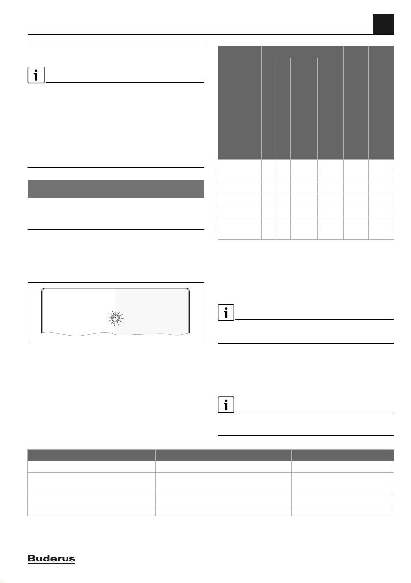
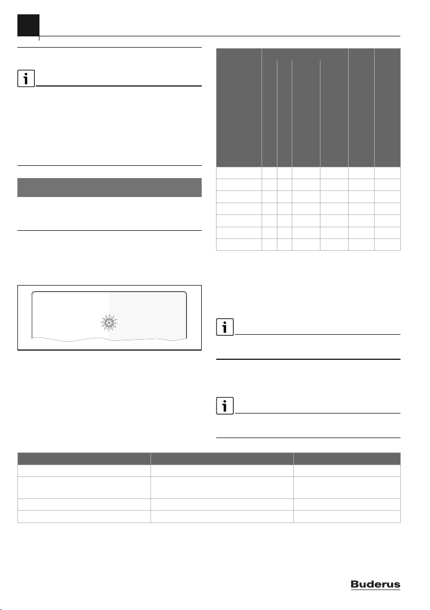
4.1 Kodierschalter einstellen
Kodierschalter mit Betriebsanzeige des Moduls und Zustandsanzeige der angeschlossenen Wärmeerzeuger oder Module:
0 010 013 313-001
Bild 5 Kodierschalter mit Zustandsanzeige des Moduls und
Zustandsanzeige der angeschlossenen Wärmeerzeuger oder Module
Kodierung Funktion des Moduls
Ausgang Störung
Leistungssteuerung des
Ansteuerung 2. Magnetventil
1)
0
– – – – – –
Vorlauftemperaturregelung des
Pumpenregelung über
Pumpenregelung über 0-10 V
Wärmeerzeugers
Wärmeerzeugers
1 – –
2 – –
3 – – –
4 – – –
5 – – – –
2)
6-10
– – – – – –
1) Aus (Lieferzustand)
2) Ungenutzt
Tab. 5 Kodierung und Funktion
4.2 Inbetriebnahme der Anlage und des Moduls
Falls eine Bedieneinheit angeschlossen ist, automatischen Konfigurationsassistenten starten.
4.3 Menü Einstellungen EM100
Die Einstellungen von EM100 können über die Bedieneinheit
( Tab. 6 "Menü EM100") vorgenommen werden.
PWM-Signal
Grundeinstellungen sind in der folgenden Tabelle hervorgehoben dargestellt.
Menüpunkt Einstellungen/Einstellbereich Bemerkung/Einschränkung
PM10 Pumpenmodulation Ja | Nein
PM10 Regelungsart Leistung | 0,5 ... 2,5 ... 10 K Auswahl von Leistungsregelung
oder Temperaturregelung.
PM10 Spg. min. Volumen 0 ... 10 V
PM10 Spg. max. Volumen 0 ... 10 V
Tab. 6 Menü EM100
EM100 – 6720891034 (2019/04)
9
Page 10
5
0
1
2
3
4
5
6
7
8
9
10
Störungen beheben
5 Störungen beheben
Nur Originalersatzteile verwenden. Schäden, die durch nicht
vom Hersteller gelieferte Ersatzteile entstehen, sind von der
Haftung ausgeschlossen.
▶ Wenn sich eine Störung nicht beheben lässt, bitte an den
zuständigen Servicetechniker wenden.
Wenn der Kodierschalter bei eingeschalteter Spannungsversorgung > 2 s auf 0 gedreht wird, werden alle Ausgänge des Moduls auf Grundstellung zurückgesetzt und Störungen gelöscht.
▶ Das Modul erneut in Betrieb nehmen.
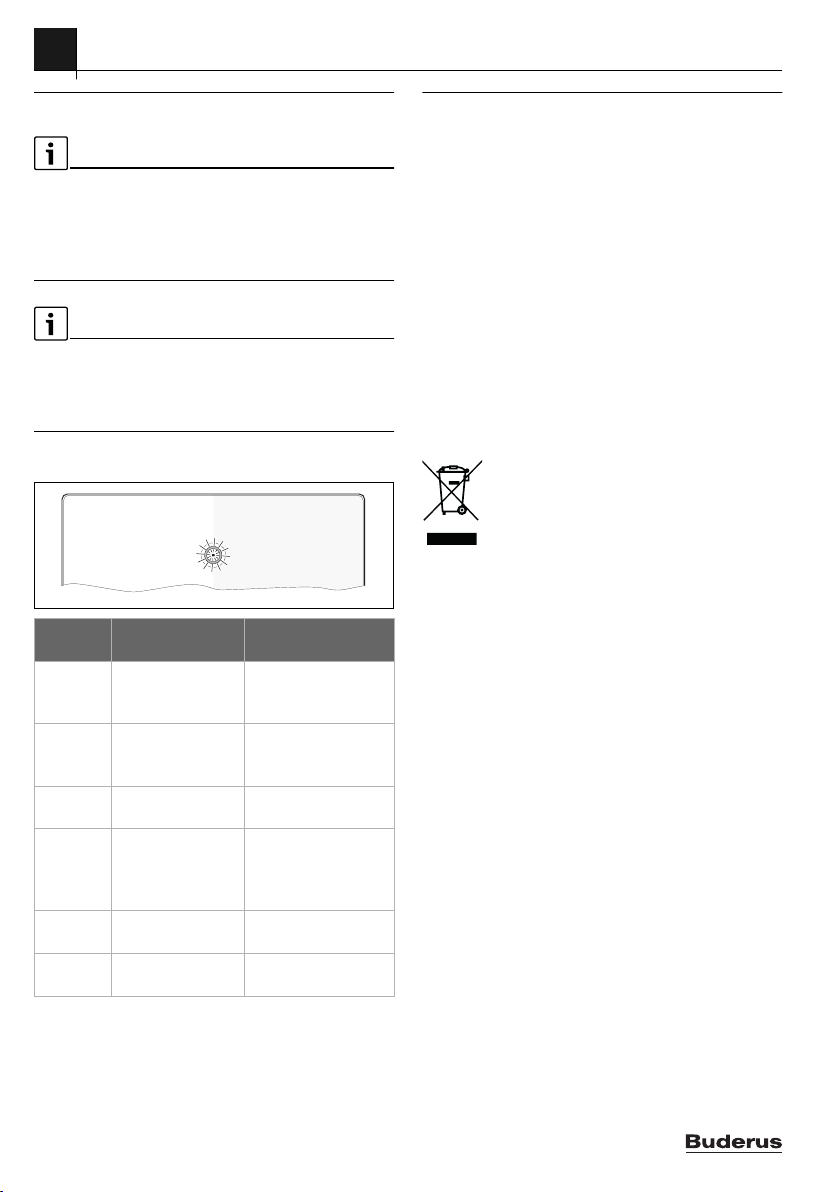
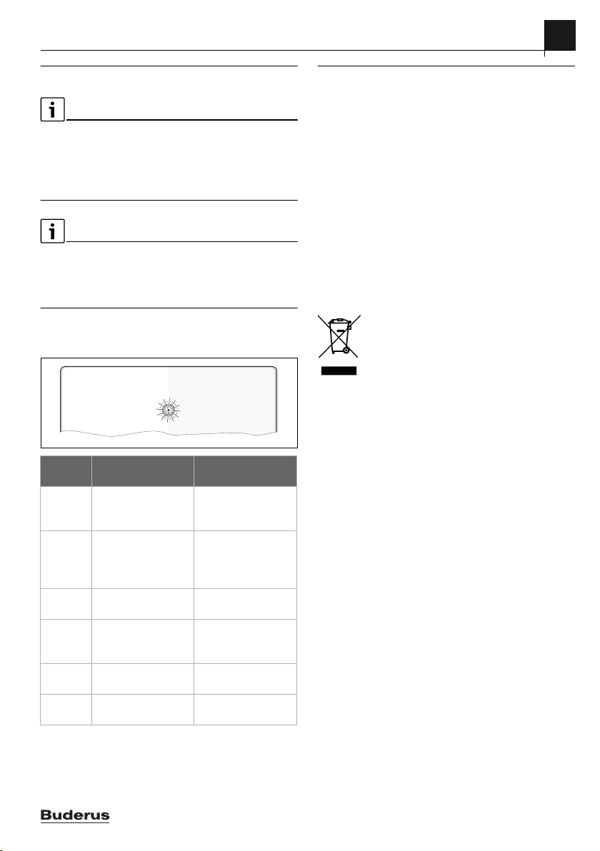
Die Betriebsanzeige zeigt den Betriebszustand des Moduls.
0 010 013 313-001
Betriebsanzeige
Dauernd rot Ungültige Schalter-
Blinkt rot Temperaturfühler
Dauernd
gelb
Blinkt grün Keine Kommunikati-
Dauernd
grün
Dauernd
aus
Tab. 7
Mögliche Ursachen Abhilfe
▶ Modul austauschen
position oder interne
Störung
oder gültige Schalterposition wählen.
▶ Temperaturfühler
defekt oder Alarmausgang Pumpe
tauschen bzw. Pumpenfehler beheben.
Kodierschalter auf 0 ▶ Richtige Kodierstel-
lung auswählen.
▶ BUS-Verbindung
on zum BUS-System
zum EMS-Bus herstellen bzw. überprüfen.
Keine Störung,
▶ –
Normalbetrieb
Keine Spannungsversorgung
▶ Modul mit Netzspan-
nung versorgen.
6 Umweltschutz/Entsorgung
Umweltschutz ist ein Unternehmensgrundsatz der Bosch
Gruppe.
Qualität der Produkte, Wirtschaftlichkeit und Umweltschutz
sind für uns gleichrangige Ziele. Gesetze und Vorschriften zum
Umweltschutz werden strikt eingehalten.
Zum Schutz der Umwelt setzen wir unter Berücksichtigung
wirtschaftlicher Gesichtspunkte bestmögliche Technik und Materialien ein.
Verpackung
Bei der Verpackung sind wir an den länderspezifischen Verwertungssystemen beteiligt, die ein optimales Recycling gewährleisten.
Alle verwendeten Verpackungsmaterialien sind umweltverträglich und wiederverwertbar.
Elektro- und Elektronik-Altgeräte
Nicht mehr gebrauchsfähige Elektro- oder
Elektronikgeräte müssen getrennt gesammelt und
einer umweltgerechten Verwertung zugeführt
werden (Europäische Richtlinie über Elektro- und
Elektronik-Altgeräte).
Nutzen Sie zur Entsorgung von Elektro- oder Elektronik-Altgeräten die länderspezifischen Rückgabe- und Sammelsysteme.
10
EM100 – 6720891034 (2019/04)
Page 11
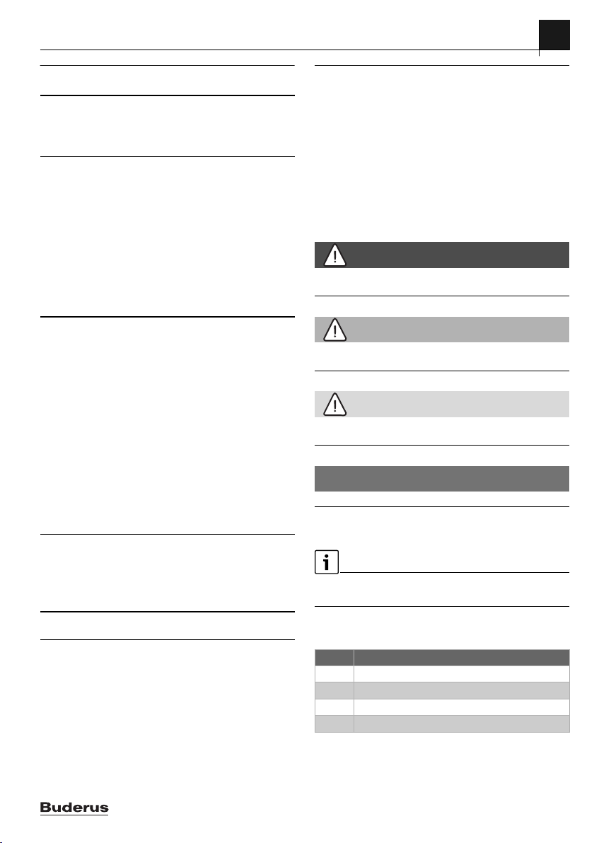
Table of contents 1 Explanation of symbols and safety
instructions
1 Explanation of symbols and safety instructions. . . .11
1.1 Explanation of symbols . . . . . . . . . . . . . . . . . . . . .11
1.2 General safety instructions . . . . . . . . . . . . . . . . . .12
2 Product Information . . . . . . . . . . . . . . . . . . . . . . . . . . .13
2.1 Important notices on use . . . . . . . . . . . . . . . . . . .13
2.2 Controls of the heat source. . . . . . . . . . . . . . . . . .13
2.2.1 Output control. . . . . . . . . . . . . . . . . . . . . . . . . . . .13
2.2.2 Flow temperature control. . . . . . . . . . . . . . . . . . .14
2.3 Supplied parts . . . . . . . . . . . . . . . . . . . . . . . . . . . .14
2.4 Specification . . . . . . . . . . . . . . . . . . . . . . . . . . . . .14
2.5 Additional accessories . . . . . . . . . . . . . . . . . . . . .15
2.6 Cleaning . . . . . . . . . . . . . . . . . . . . . . . . . . . . . . . . .15
3 Installation . . . . . . . . . . . . . . . . . . . . . . . . . . . . . . . . . . .15
3.1 Preparation for the installation in the heat
source . . . . . . . . . . . . . . . . . . . . . . . . . . . . . . . . . .15
3.2 Installation locations . . . . . . . . . . . . . . . . . . . . . . .15
3.3 Installation of a temperature sensor on the
low loss header or downstream of the heat
exchanger. . . . . . . . . . . . . . . . . . . . . . . . . . . . . . . . 15
3.4 Electrical connection. . . . . . . . . . . . . . . . . . . . . . .16
3.4.1 Establishing the BUS connection and
temperature sensor (extra-low voltage side). . . .16
3.4.2 Connecting the power supply, pump,
solenoid valve or fault display (mains voltage
side) . . . . . . . . . . . . . . . . . . . . . . . . . . . . . . . . . . . . 16
3.4.3 Overview of the terminal assignment . . . . . . . . .17
4 Commissioning . . . . . . . . . . . . . . . . . . . . . . . . . . . . . . .18
4.1 Setting the coding switch . . . . . . . . . . . . . . . . . . .18
4.2 Commissioning of the system and module . . . . .18
4.3 Settings menu EM100 . . . . . . . . . . . . . . . . . . . . .18
1.1 Explanation of symbols
Warnings
In warnings, signal words at the beginning of a warning are used
to indicate the type and seriousness of the ensuing risk if
measures for minimising danger are not taken.
The following signal words are defined and can be used in this
document:
DANGER:
DANGER indicates that severe or life-threatening personal
injury will occur.
WARNING:
WARNING indicates that severe to life-threatening personal
injury may occur.
CAUTION:
CAUTION indicates that minor to medium personal injury may
occur.
NOTICE:
NOTICE indicates that material damage may occur.
Important information
The info symbol indicates important information where there is
no risk to people or property.
Table of contents
5 Troubleshooting. . . . . . . . . . . . . . . . . . . . . . . . . . . . . . . 19
6 Environmental protection/disposal . . . . . . . . . . . . . .19
EM100 – 6720891034 (2019/04)
Additional symbols
Symbol Meaning
▶ a step in an action sequence
a reference to a related part in the document
• a list entry
– a list entry (second level)
Table 1
11
Page 12

1
Explanation of symbols and safety instructions
1.2 General safety instructions
H Notes for the target group
These installation instructions are
intended for gas, plumbing, heating and
electrical contractors. All instructions
must be observed. Failure to comply
with instructions may result in material
damage and personal injury, including
danger to life.
▶ Read the installation instructions
(heat source, heating controller, etc.)
before installation.
▶ Observe the safety instructions and
warnings.
▶ Observe national and regional
regulations, technical rules and
guidelines.
▶ Record all work carried out.
H Determined use
▶ Use the product only to control
heating systems.
Any other use is considered
inappropriate. We take no responsibility
for damage caused through incorrect use.
H Installation, commissioning and
maintenance
Installation, commissioning and
maintenance must only be carried out by
a competent person.
▶ Never install the product in wet rooms.
▶ Only use genuine spare parts.
H Electrical work
Electrical work must only be carried out
by a qualified electrician.
▶ Before starting electrical work:
– Isolate all poles of the mains power
supply and secure against
reconnection.
– Make sure the mains voltage is
disconnected.
▶ The product requires different
voltages.
Do not connect the extra-low voltage
side to the mains voltage or vice versa.
▶ Also observe the connection
diagrams of other system
components.
H Handover to the user
When handing over, instruct the user
how to operate the heating system and
inform the user about its operating
conditions.
▶ Explain how to operate the heating
system and draw the user's attention
to any safety relevant action
▶ Explain that conversions and repairs
must only be carried out by a
competent person.
▶ Point out the need for inspections and
maintenance for safe and
environmentally-compatible operation.
▶ Leave the installation instructions and
the operating instructions with the
user for safekeeping.
12
EM100 – 6720891034 (2019/04)
Page 13
2 Product Information
H Damage caused by frost
The system can freeze if it is switched off:
▶ Observe the notices regarding frost
protection.
▶ Due to the additional functions, e.g.
DHW heating or pump anti-seizure
protection, the system should always
be left on.
▶ Have faults rectified immediately.
2 Product Information
• The module can adjust the boiler flow temperature or the
boiler output via an external control signal with 0–
10 V (direct voltage).
• The module signals faults in the floor standing boiler and
system faults, apart from service displays, faults in external
controllers or maintenance for the installer.
• The module can be used to activate a second solenoid valve
and for boiler versions operated with liquid gas.
• The module serves as an expansion module for EMS and
EMS plus boilers.
• The module serves as the modulating speed control “Flow
Control” of a boiler circulation pump (0-10 V or PWM) in
combination with a low loss header or heat exchanger.
The boiler circulation pump adapts the flow rate on the
boiler side and prevents an increase in the return
temperature of the boiler. The objective is to optimise the
utilisation of calorific value and to save power. The choice of
0-10 V or PWM signal makes the function suitable for floor
standing heat sources and wall-mounted indoor units
GB162 >45 kW with factory-installed pump assembly.
3 control types can be selected:
1. Flow temperature control: difference between heating flow
and system flow
2. Power regulation: parallel to boiler output (if additional
sensor is not possible)
3. Difference between heating flow and return
(recommended for heat exchangers)
The combination options for the modules are shown in the
connection diagrams.
(recommended for low loss header)
2.1 Important notices on use
• The range of functions depends on the control unit
installed. Detailed information on control units can be
found in the technical guide and on the website of the
manufacturer.
• The installation room must be appropriate for the IP rating
stated in the technical data of the module.
2.2 Controls of the heat source
This control strategy is used when the heating system is
controlled using a building management system with a 0–10 V
controller output ( Fig. 22 at the end of the document).
Input voltage Flow
0 V - 0.5 V 0 %/0 °C off
0.6 V approx. 6 %/
5.0 V approx. 50 %/
10.0 V approx. 100 %/
Table 2 Control based on output/flow temperature
2.2.1 Output control
Linear relationship between the 0–10 V signal (U in volts) and
the required performance (P in percent)
P / %
100
10
0,5
110
Fig. 1 Linear relationship between the 0–10 V signal (U in
The connected heat sources are enabled and disabled
according to the required output.
volts) and the required performance P (in percent
with reference to the maximum system
performance)
temperature/
output setpoint
(boiler)
approx. 15 °C
approx. 50 °C
approx. 90 °C
Boiler status
on if > min. output
on
on/maximum
U / V
0010013227-002
EM100 – 6720891034 (2019/04)
13
Page 14
2
Product Information
2.2.2 Flow temperature control
Linear relationship between the 0–10 V signal (U in volts) and
the required flow temperature in °C with reference to the
minimum flow temperature range to the maximum flow
temperature range [default setting 20 to 90 °C]):
/ °C
90
20
0,5
110
U / V
0010024409-001
Fig. 2 Linear relationship between the 0–10 V signal (U in
volts) and the required flow temperature in °C)
The connected heat sources are enabled and disabled
according to the required flow temperature.
2.3 Supplied parts
Fig. 6 at end of document:
[1] Module
[2] Bag with strain relief
[3] Installation Manual
2.4 Specification
This product conforms to European directives and
supplementary national requirements in design and
marking.
You can request the conformity declaration of the product. If
you require this, contact the address on the back cover of these
instructions.
operation. Compliance is demonstrated by the CE
Specification
Dimensions (W × H × D)
151 × 184 × 61 mm (for more
dimensions Fig.
document)
Maximum conductor crosssection
• 230 V terminal • 2.5 mm
• Extra-low voltage terminal • 1.5 mm
7
at end of
2
2
Specification
Rated voltages
• BUS • 15 V DC
(reverse polarity
protected)
• Module mains voltage • 230 V AC, 50 Hz
• User interface • 15 V DC
(reverse polarity
protected)
• Pump, solenoid valve,
• 230 V AC, 50 Hz
interference output
Fuse 230 V, 5 AT
BUS interface EMSand EMS plus
Power consumption –
< 3 W
Standby
Max. power output
• per connection(PC0)
• 400 W (high-efficiency
pumps permissible:
<30 A for 10 ms)
• per connection(OE1)
• 120 W (high-efficiency
pumps permissible:
< 30 A for 10 ms)
Permitted ambient
0 ... 60 °C
temperature
IP rating IP 44
Protection class I
ID no. Data plate ( Fig. 21 at the
end of document)
Table 3
°C °C °C
20 12486 50 3605 80 1256
25 10000 55 2989 85 1070
30 8060 60 2490 90 915
35 6536 65 2084 100 677
40 5331 70 1753 – –
45 4372 75 1480 – –
Table 4 Measurements of low loss header temperature
sensor (T0)
14
EM100 – 6720891034 (2019/04)
Page 15
3 Installation
2.5 Additional accessories
For detailed information about suitable accessories, refer to
the catalogue or Internet page of the manufacturer.
• Low loss header temperature sensor; connection to T0
• Primary pump; connection to PC0
Installation of additional accessories
▶ Install the additional accessories in accordance with legal
regulations and the instructions supplied.
2.6 Cleaning
▶ Wipe the casing with a damp cloth when necessary. Never
use aggressive or caustic cleaning agents for this.
3 Installation
DANGER:
Danger to life from electric shock!
Touching live electrical parts can cause an electric shock.
▶ Before installing this product: Disconnect the heat source
and all other BUS nodes from the mains voltage across all
poles.
▶ Before commissioning: Mount the cover
( Fig. 20 at end of document).
3.1 Preparation for the installation in the heat
source
▶ Check by referring to the installation instructions of the
heat source whether it is possible to install modules
(e.g. EM100) in the heat source.
▶ If the module can be installed in the heat source without a
mounting rail, prepare the module ( Fig. 8 and 9 at end
of document).
3.2 Installation locations
▶ Install the module on a wall, ( Fig. 10 and 11 at end
of document), on a mounting rail ( Fig. 12 at end of
document), in an assembly or in the heat source.
▶ When the module is installed in a heat source, observe the
heat source instructions.
▶ Remove the module from the mounting rail
( Fig. 13 at end of document).
3.3 Installation of a temperature sensor on the
low loss header or downstream of the heat
exchanger
The low loss header temperature sensor T0 should as a priority
be connected to EM100. In wall mounted boilers equipped with
EMS plus, the sensor can also be connected to the device or a
MM100.
Installation on the low-loss header
( Fig. 23 and 25 at the end of the document)
Position of flow temperature sensor (T0):
A
ϑ
1
T0
12
ϑ
2
Fig. 3 Position of flow temperature sensor (T0)
[1] all heat sources
[2] all heating circuits
A low loss header model 1
B low loss header model 2
overall flow temperature of all heat sources
1
overall return temperature of all heat sources
2
overall flow temperature of all heating circuits
3
overall return temperature of all heating circuits
4
T0 flow temperature sensor on the low loss header
T0 must be positioned so
sources [1] independently of the flow rate. This is the only way
also to ensure stable operation of the control with small loads.
To ensure optimum control response, the flow should circulate
around the temperature sensor. This can be achieved by a
combination of tee, tap extension and sensor set.
B
ϑ
3
ϑ
1
1
ϑ
ϑ
4
2
0 010 013 230-001
is detected on the side of all heat
3
T0
ϑ
ϑ
3
2
4
EM100 – 6720891034 (2019/04)
15
Page 16
3
Installation
Optimised sensor installation downstream of the heat
exchanger
The temperature sensor (T0) must be mounted on the flow
downstream of the heat exchanger on the secondary side
(wet sensor) ( Fig. 24 at end of document).
There are two ways to ensure optimised sensor installation
downstream of the heat exchanger ( Item [1] with angled
screw connection and Item [2], Fig. 4 "Optimised sensor
installation"):
24
B
A
1
T0
24
B
A
2
T0
0010024454-001
Fig. 4 Optimised sensor installation
The temperature sensor must be positioned so the
measurement is taken at the centre of the pipe.
▶ Use tap extensions to adjust the installation depth of the low
loss header temperature sensor ( Installation instructions
of low loss header sensor set). If installed correctly, the
sensor projects 1-2 cm into the heat exchanger.
3.4 Electrical connection
▶ Obser ve electrical regulations and use at least
cable H05 VV-...
3.4.1 Establishing the BUS connection and temperature
sensor (extra-low voltage side)
▶ If the conductor cross-sections vary, use a junction box to
connect the BUS nodes.
▶ Switch BUS nodes [B] via the junction box[A] in star
( Fig. 18 at end of document) or via BUS nodes with 2
BUS connections in series.
If the maximum total length of the BUS connections between all
BUS nodes is exceeded or the BUS system has a ring structure,
commissioning of the system is not possible.
Maximum total length of BUS connections:
• 100 m with 0.50 mm
• 300 m with 1.50 mm
2
conductor cross-section
2
conductor cross-section
▶ To avoid inductive interference: Make sure all low-voltage
cables are routed separately from supply voltage carrying
cables (min. clearance 100 mm).
▶ In the case of external inductive effects (e.g. from PV systems)
use shielded cable (e.g. LiYCY) and ground one end of the
shield. |Connect the shield to the building's earthing system,
e.g. to a free earth conductor terminal or water pipes, and not
to the connecting terminal for earth leads in the module.
When extending the sensor leads, use the following conductor
cross-sections:
• 0.75 to 1.50 mm
• 1.50 mm
2
conductor cross-section for up to 20 m
2
conductor cross-section for 20 m to 100 m
▶ Route cables through the grommets provided and connect
them as shown in the connection diagrams.
3.4.2 Connecting the power supply, pump, solenoid valve
or fault display (mains voltage side)
The assignment of the electrical connection depends on which
system is installed. The description at the end of the document
in Fig. 14 to 17 is a possible suggestion for the electrical
connection. Not all steps are shown in black. This makes it
easier to see, which steps belong together.
▶ Only use electric cables of the same quality.
▶ Make sure the power supply is connected to the correct
phases.
A power supply via an earthed safety plug is not permissible.
▶ Connect only components and assemblies to the outputs as
described in these instructions. Do not connect any
additional controls that operate other system components.
▶ Route cables through the grommets, connect them as
shown in the connection diagrams and secure them with
the strain relief devices included in the scope of delivery
( Fig. 14 to 17 at the end of this document).
The maximum power consumption of the connected
components and assemblies must not exceed the power output
stated in the specifications for the module.
▶ If the mains voltage is not supplied via the electronic system
of the heat source: Install a standard all-pole isolator
(in accordance with EN 60335-1) on site to interrupt the
mains voltage.
16
EM100 – 6720891034 (2019/04)
Page 17
3 Installation
0
1
2
3
4
5
6
7
8
9
10
0
1
2
3
4
5
6
7
8
9
10
3.4.3 Overview of the terminal assignment
This overview indicates which system parts can be connected.
EM100
120/230 V AC
230 VAC
OE1 PC0
N
L
OE1 OE1
120/230VAC120/230VAC
NL N N74 N6375L
230 VAC
Caption to the figure above and connection diagrams with
system schematics at end of document:
Earth connection
Connecting terminal designations:
230 V AC Mains voltage connection
BUS BUS system connection
BMS Building Management System with 0-10 V interface
HS Heat Source on BUS system
OE1-74 Mains voltage output, solenoid valve
OE1-75 Fault output (230 V)
PC0 Mains voltage output, pump (230 V)
IE0 Pump alarm output
OP0 Pump on/off (output/potential-free contact ≤ 24 V)
T0 Low loss header temperature sensor input
IO1-1,2 Heat source feedback output (0–10 V)
IO1-3,4 Heat source activation input (0–10 V)
OC0 1-2 Pump control signal output (0-10 V/PWM)
OC0 1-3 Pump check-back signal input (PWM), optional
CON Control unit with BUS system (Controller)
MC Boiler control device (Master Controller)
MM 100 Heating circuit module (EMS/EMS plus)
EM100 Extension module
IE0 OP0
1212 12
NL
M
PC0
1)
2)
3)
3)
Depending on what the module is used for (coding at the
module and configuration via the control unit), connect the
system parts as specified in the corresponding connection
diagram.
≤ 24 V
IO141OC0
213 23
OC0
3
≤ 24 V
OP0IE0
T0
12
T0
BUS
BUS
0-10 V
(+) (–)12(+) (–)
IO1
0-10 V
34
IO1
123
0-10V
OC0
21
123
PWM
OC0
0010025508-001
1) The pump can also be connected directly to the building
circuit breaker if continuous current is required.
2) With the heat exchanger, T0 is the flow temperature
sensor.
3) Observe coding switch position.
EM100 – 6720891034 (2019/04)
17
Page 18
4
0
1
2
3
4
5
6
7
8
9
10
Commissioning
4 Commissioning
First make all electrical connections and then carry out the
commissioning!
▶ Observe the installation instructions for all components
and assemblies in the system.
▶ Only switch on the power supply if the coding switch is set up.
▶ If a control unit is connected, it is recommended to start the
configuration wizard.
NOTICE:
Risk of damage to system through pump failure!
▶ Fill and vent the system before switching it on so that the
pumps do not run dry.
4.1 Setting the coding switch
Coding switch with On/Off indicator of the module and a status
display of the connected heat sources or modules:
0 010 013 313-001
Fig. 5 Coding switch with module status display, and a status
display of the connected heat sources or modules
Coding Function of module
Fault output
Output control of the
2nd solenoid valve activation
1)
0
– – – – – –
Flow temperature control of the
Pump control via
Pump control via 0-10 V
heat source
heat source
1 – –
2 – –
3 – – –
4 – – –
5 – – – –
2)
6-10
– – – – – –
1) Off (delivered condition)
2) Unused
Table 5 Coding and function
4.2 Commissioning of the system and module
If a control unit is connected, start the automatic configuration
wizard.
PWM signal
4.3 Settings menu EM100
The settings of the EM100 can be made via the control unit
( Table 6 "EM100 menu").
The basic settings are depicted as highlighted in the following
table.
Menu item Settings/adjustment range Remark/restriction
PM10 pump modulation Yes | No
PM10 control type Output | 0.5 ... 2.5 ... 10 K Selection of output control or
PM10 voltage min. vol. 0 ... 10 V
PM10 voltage max. vol. 0 ... 10 V
Table 6 EM100 menu
18
EM100 – 6720891034 (2019/04)
temperature control.
Page 19
5 Troubleshooting
0
1
2
3
4
5
6
7
8
9
10
5 Troubleshooting
Use only original spare parts. Damage caused by the use of
spare parts not supplied by the manufacturer is excluded from
the warranty.
▶ If a fault cannot be rectified, please contact your local
service engineer.
If the coding switch is set to 0 for > 2 s when the power supply
is switched on, all outputs of the module are reset to their
default settings and faults are deleted.
▶ Restart the module.
The On/Off indicator indicates the operating condition of the
module.
0 010 013 313-001
Status
indicator
Constantly
red
Red
flashing
Constantly
yellow
Green
flashing
Constantly
green
Constantly
OFF
Table 7
Possible causes Remedy
Invalid switch position
or internal fault
▶ Replace the module
or select valid
switch position.
Temperature sensor
faulty or pump alarm
output
▶ Replace
temperature sensor
or eliminate pump
fault.
Coding switch set to 0 ▶ Select the correct
encoding position.
No communication
with the BUS system
▶ Establish the BUS
connection to the
EMS BUS.
No fault, normal
▶ –
operation
Lack of electrical
supply
▶ Supply the module
with mains voltage.
6 Environmental protection/disposal
Environmental protection is a key commitment of the Bosch
Group.
Quality of products, efficiency and environmental protection
are equally important objectives for us. Environmental
protection laws and regulations are strictly observed.
To protect the environment, we use the best possible
technology and materials while taking into account economic
considerations.
Packaging
Where packaging is concerned, we participate in countryspecific recycling processes that ensure optimum recycling.
All of our packaging materials are environmentally compatible
and can be recycled.
Old electrical and electronic appliances
Electrical or electronic appliances that are no
longer serviceable must be collected separately
and sent for environmentally compatible recycling
(in accordance with the European Directive on
Waste Electrical and Electronic Equipment).
To dispose of old electrical or electronic appliances, you should
use the return and collection systems put in place in the country
concerned.
EM100 – 6720891034 (2019/04)
19
Page 20
Inhoudsopgave
Inhoudsopgave 1 Toelichting bij de symbolen en
veiligheidsinstructies
1 Toelichting bij de symbolen en
veiligheidsinstructies . . . . . . . . . . . . . . . . . . . . . . . . . . 20
1.1 Symboolverklaringen. . . . . . . . . . . . . . . . . . . . . . . 20
1.2 Algemene veiligheidsvoorschriften. . . . . . . . . . . . 21
2 Gegevens betreffende het product. . . . . . . . . . . . . . . 22
2.1 Belangrijke adviezen voor het gebruik . . . . . . . . . 22
2.2 Regeling van de warmteproducent . . . . . . . . . . . . 22
2.2.1 Vermogensregeling . . . . . . . . . . . . . . . . . . . . . . . . 22
2.2.2 Aanvoertemperatuurregeling . . . . . . . . . . . . . . . . 22
2.3 Leveringsomvang . . . . . . . . . . . . . . . . . . . . . . . . . . 23
2.4 Technische gegevens . . . . . . . . . . . . . . . . . . . . . . . 23
2.5 Aanvullend toebehoren . . . . . . . . . . . . . . . . . . . . . 23
2.6 Reiniging. . . . . . . . . . . . . . . . . . . . . . . . . . . . . . . . . 23
3 Installatie . . . . . . . . . . . . . . . . . . . . . . . . . . . . . . . . . . . . 24
3.1 Voorbereiding voor installatie in de cv-ketel. . . . . 24
3.2 Installatieplaatsen . . . . . . . . . . . . . . . . . . . . . . . . . 24
3.3 Installatie van een temperatuursensor op de
evenwichtsfles, of achter de warmtewisselaar . . . 24
3.4 Elektrische aansluiting. . . . . . . . . . . . . . . . . . . . . . 25
3.4.1 Aansluiting BUS-verbinding en
temperatuursensor (laagspanningszijde). . . . . . . 25
3.4.2 Aansluiting voedingsspanning pomp,
magneetventiel of storingsindicatie
(netspanningszijde). . . . . . . . . . . . . . . . . . . . . . . . 25
3.4.3 Overzicht bezetting aansluitklemmen . . . . . . . . . 26
4 Inbedrijfstelling . . . . . . . . . . . . . . . . . . . . . . . . . . . . . . . 27
4.1 Codeerschakelaar instellen . . . . . . . . . . . . . . . . . . 27
4.2 Inbedrijfstelling van de installatie en de
module . . . . . . . . . . . . . . . . . . . . . . . . . . . . . . . . . . 27
4.3 Menu instellingen EM100 . . . . . . . . . . . . . . . . . . . 27
1.1 Symboolverklaringen
Waarschuwingen
Bij waarschuwingen geven signaalwoorden de soort en de ernst
van de gevolgen aan indien de maatregelen ter voorkoming van
het gevaar niet worden opgevolgd.
De volgende signaalwoorden zijn vastgelegd en kunnen in dit
document worden gebruikt:
GEVAAR:
GEVAAR betekent dat zwaar tot levensgevaarlijk lichamelijk
letsel zal ontstaan.
WAARSCHUWING:
WAARSCHUWING betekent dat zwaar tot levensgevaarlijk
lichamelijk letsel kan ontstaan.
VOORZICHTIG:
VOORZICHTIG betekent, dat licht tot middelzwaar persoonlijk
letsel kan ontstaan.
OPMERKING:
OPMERKING betekent dat materiële schade kan ontstaan.
Belangrijke informatie
Belangrijke informatie, zonder gevaar voor mens of materialen,
wordt met het getoonde info-symbool gemarkeerd.
5 Storingen verhelpen . . . . . . . . . . . . . . . . . . . . . . . . . . . 28
6 Milieubescherming/afvalverwerking . . . . . . . . . . . . . 28
20
Aanvullende symbolen
Symbool Betekenis
▶ Handelingsstap
Kruisverwijzing naar een andere plaats in
het document
• Opsomming/lijstpositie
– Opsomming/lijstpositie (2e niveau)
Tabel 1
EM100 – 6720891034 (2019/04)
Page 21

1 Toelichting bij de symbolen en veiligheidsinstructies
1.2 Algemene veiligheidsvoorschriften
H Instructies voor de doelgroep
Deze installatiehandleiding is bedoeld
voor installateurs van gas- en waterinstallaties, verwarmings- en elektrotechniek.
Houd de instructies in alle handleidingen
aan. Indien deze niet worden aangehouden kunnen materiële schade, lichamelijk
letsel en zelfs levensgevaar ontstaan.
▶ Lees de installatiehandleidingen
(warmteproducent, verwarmingsregelaar enz.) voor de installatie.
▶ Neem de veiligheidsinstructies en
waarschuwingsaanwijzingen in acht.
▶ Neem de nationale en regionale voor-
schriften, technische regels en richtlijnen in acht.
▶ Documenteer uitgevoerde werkzaam-
heden.
H Gebruik volgens de voorschriften
▶ Gebruik het product uitsluitend voor
het regelen van cv-installaties.
Ieder ander gebruik komt niet overeen met
de voorschriften. Daaruit resulterende
schade valt niet onder de fabrieksgarantie.
H Installatie, inbedrijfstelling en
onderhoud
Installatie, inbedrijfstelling en onderhoud
mogen alleen door een erkend installateur worden uitgevoerd.
▶ Installeer het product niet in vochtige
ruimten.
▶ Gebruik alleen originele reserve-on-
derdelen.
Elektrotechnische werkzaamheden
H
Elektrotechnische werkzaamheden mogen alleen door elektrotechnici worden
uitgevoerd.
▶ Vóór elektrotechnische
werkzaamheden:
– Schakel de netspanning (over alle
polen) spanningsloos en zorg ervoor
dat ze niet per ongeluk opnieuw kunnen worden ingeschakeld.
– Spanningsloosheid vaststellen.
▶ Het product heeft verschillende span-
ningen nodig.
Sluit de laagspanningszijde niet aan
op de netspanning en omgekeerd.
▶ Respecteer de aansluitschema's van
de overige installatiedelen ook.
H Overdracht aan de eigenaar
Instrueer de eigenaar bij de overdracht
in de bediening en bedrijfsomstandigheden van de cv-installatie.
▶ Leg de bediening uit – ga daarbij in
het bijzonder in op alle veiligheidsrelevante handelingen.
▶ Wijs erop, dat ombouw of herstellin-
gen alleen door een erkend installateur mogen worden uitgevoerd.
▶ Wijs op de noodzaak tot inspectie en
onderhoud voor een veilig en milieuvriendelijk bedrijf.
▶ Geef de installatie- en bedienings-
handleidingen aan de eigenaar in
bewaring.
EM100 – 6720891034 (2019/04)
21
Page 22

2
Gegevens betreffende het product
H Schade door vorst
Wanneer de installatie niet in bedrijf is,
kan deze bevriezen:
▶ Respecteer de instructies voor
vorstbeveiliging.
▶ Laat de installatie altijd ingeschakeld,
vanwege extra functies zoals bijvoorbeeld warmwaterbereiding of blokkeerbescherming.
▶ Laat optredende storingen direct
oplossen.
2 Gegevens betreffende het product
• De module kan via een extern stuursignaal met 0-10 V (gelijkspanning) de aanvoertemperatuur van de cv-ketel of het
vermogen van de cv-ketel aanpassen.
• De module meldt storingen van de cv-ketel en ook systeemstoringen, met uitzondering van de servicedisplays, storingen van externe regelaars of onderhoud voor de installateur.
• De module kan bij de sturing van een tweede magneetventiel worden gebruikt en bij cv-ketels met vloeibaar gas worden toegepast.
• De module is bedoeld als uitbreidingsmodule voor EMS- en
EMS plus-cv-ketel.
• De module is bedoeld voor de modulerende toerentalregeling “Flow Control” van een ketelcircuitpomp (0-10 V of
PWM) in combinatie met een evenwichtsfles of warmtewisselaar.
De ketelcircuitpomp past het debiet van de cv-ketel aan en
voorkomt een retourtemperatuurverhoging van de cv-ketel.
Het doel is een geoptimaliseerde condensatiebenutting en
stroombesparing. Door 0-10 V of PWM-signaal te selecteren, is de functie geschikt bij op de vloerstaande cv-ketels
en wandtoestellen GB162 >45 kW met een pompgroep af
fabriek.
Er kan uit 3 regeltypen worden gekozen:
1. Regeling van de cv-aanvoertemperatuur: Verschil cv-aanvoer
met installatie-aanvoer
2. Vermogensregeling: parallel aan het ketelvermogen
(als er geen extra sensor mogelijk is)
3. Verschil cv-aanvoer met cv-retour (aanbevolen voor
warmtewisselaar)
De combinatiemogelijkheden van de module zijn te vinden in de
aansluitschema's.
(aanbevolen voor evenwichtsfles)
2.1 Belangrijke adviezen voor het gebruik
• De functionaliteit is afhankelijk van de geïnstalleerde bedieningseenheid. Meer informatie over de bedieningseenheden vindt u in in de catalogus, de planningsdocumenten en
de website van de fabrikant.
• De opstellingsruimte moet voor de beschermingklasse conform de technische gegevens van de module geschikt zijn.
2.2 Regeling van de warmteproducent
Deze regelstrategie wordt toegepast, als de cv-installatie via
een gebouwautomatiseringssysteem met een 0-10 V-regelaaruitgang wordt geregeld ( afbeelding 22 aan het einde van het
document).
Ingangsspanning Gewenste waarde
0 V - 0,5 V 0 %/0 °C uit
0,6 V ca. 6 %/ca. 15 °C aan, wanneer >
5,0 V ca. 50 %/ca. 50 °C aan
10,0 V ca. 100 %/ca. 90 °C aan / maximum
Tabel 2 Regeling volgens vermogen/aanvoertemperatuur
2.2.1 Vermogensregeling
Lineaire relatie tussen 0-10 V-signaal (U in Volt) en gevraagde
vermogen (P in procenten gerelateerd aan het maximale
vermogen van de installatie):
P / %
100
10
0,5
Afb. 1 Lineaire relatie tussen 0-10 V-signaal (U in Volt) en
De aangesloten warmteproducenten worden conform het
gevraagde vermogen in- of uitgeschakeld.
2.2.2 Aanvoertemperatuurregeling
Lineaire relatie tussen 0-10 V-signaal (U in Volt) en gevraagde
aanvoertemperatuur in °C gerelateerd aan het bereik mini-
male aanvoertemperatuur tot maximale aanvoertemperatuur
[fabrieksinstelling 20 tot 90 °C]):
aanvoertemperatuur/
vermogen (cv-ketel)
110
gevraagde vermogen (P in procenten)
Status cv-ketel
min. vermogen
U / V
0010013227-002
22
EM100 – 6720891034 (2019/04)
Page 23

2 Gegevens betreffende het product
/ °C
90
20
0,5
110
U / V
0010024409-001
Afb. 2 Lineaire relatie tussen 0-10 V-signaal (U in Volt) en
gevraagd vermogen van de aanvoertemperatuur
in °C)
De aangesloten warmteproducenten worden conform de gevraagde aanvoertemperatuur in- of uitgeschakeld.
2.3 Leveringsomvang
Afb. 6 aan het einde van het document:
[1] Module
[2] Zak met trekontlastingen
[3] Installatiehandleiding
2.4 Technische gegevens
Dit product voldoet qua constructie en werking aan
de Europese richtlijnen evenals aan de bijkomende
toond door het CE-kenmerk.
De conformiteitverklaring van het product kunt u aanvragen.
Neem daarvoor contact op met het adres vermeld op de achterkant van deze handleiding.
nationale vereisten. De conformiteit wordt aange-
Technische gegevens
Afmetingen (B × H × D) 151 × 184 × 61 mm (overige
maten afb. 7 aan het eind
van het document)
Maximale geleiderdiameter
• Aansluitklem 230 V • 2,5 mm
• Aansluitklem laagspanning
• 1,5 mm
2
2
Nominale spanningen
• BUS
• 15 V DC
(beveiligd tegen ompolen)
• Netspanning module • 230 V AC, 50 Hz
• Bedieningseenheid
• 15 V DC
(beveiligd tegen ompolen)
• Pomp, magneetventiel,
• 230 V AC, 50 Hz
storingsuitgang
Zekering 230 V, 5 AT
BUS-interface EMS en EMS plus
Technische gegevens
Opgenomen vermogen –
< 3 W
standby
max. vermogen
• Per aansluiting (PC0)
• 400 W (hoogrendementpompen toegelaten:
< 30 A gedurende 10 ms)
• Per aansluiting (OE1)
• 120 W (hoogrendementpompen toegelaten:
< 30 A gedurende 10 ms)
Toegest. omgevingstemp. 0 ... 60 °C
Beschermingsklasse IP 44
Veiligheidsklasse I
Identificatienummer Typeplaat ( afb. 21 aan ein-
de van het document)
Tabel 3
°C °C °C
20 12486 50 3605 80 1256
25 10000 55 2989 85 1070
30 8060 60 2490 90 915
35 6536 65 2084 100 677
40 5331 70 1753 – –
45 4372 75 1480 – –
Tabel 4 Meetwaarden evenwichtsflestemperatuursensor (T0)
2.5 Aanvullend toebehoren
Exacte informatie over geschikt toebehoren is opgenomen in de
catalogus of de internetpagina van de fabrikant.
• Evenwichtsflestemperatuursensor: aansluiting op de T0
• Primaire pomp: aansluiting op de PC0
Installatie van de aanvullende toebehoren
▶ Installeer de aanvullende toebehoren overeenkomstig de
wettelijke voorschriften en de meegeleverde handleidingen.
2.6 Reiniging
▶ Indien nodig met een vochtige doek de behuizing schoon
wrijven. Gebruik daarbij geen scherpe of bijtende reinigingsmiddelen.
EM100 – 6720891034 (2019/04)
23
Page 24

3
Installatie
3 Installatie
GEVAAR:
Levensgevaar door elektrische stroom!
Aanraken van elektrische onderdelen die onder spanning staan
kan een elektrische schok veroorzaken.
▶ Voor de installatie van dit product: warmteproducent en
alle andere BUS-deelnemers over alle polen losmaken van
de netspanning.
▶ Voor de inbedrijfstelling: breng de afdekking aan
( afb. 20 aan het einde van het document).
3.1 Voorbereiding voor installatie in de cv-ketel
▶ Via de installatiehandleiding van de warmteproducent con-
troleren, of deze de mogelijkheid biedt, een module (bijvoorbeeld EM100) in de warmteproducent te installeren.
▶ Wanneer de module zonder rail in de warmteproducent kan
worden geïnstalleerd, de module voorbereiden
( afbeelding 8 en 9 aan het einde van het document).
3.2 Installatieplaatsen
▶ De module aan een wand ( afbeelding 10 en 11 aan het
einde van het document), aan een rail ( afbeelding 12
aan het einde van het document), in een bouwgroep of in de
warmteproducent installeren.
▶ Respecteer de handleiding bij montage van de module in
een cv-ketel.
▶ Verwijder de module van de rail
( afb. 13 aan einde document).
3.3 Installatie van een temperatuursensor op
de evenwichtsfles, of achter de
warmtewisselaar
De evenwichtsflestemperatuursensor T0 moet met prioriteit
met de EM100 worden verbonden. Bij cv-ketels met EMS plus
kan de sensor ook op het toestel of een MM100 worden aangesloten.
Installatie op de evenwichtsfles
( afbeelding 23 en 25 aan het einde van het document)
Positie temperatuursensor aanvoer (T0):
A
ϑ
1
T0
12
ϑ
2
B
ϑ
3
ϑ
1
1
ϑ
ϑ
4
2
T0
ϑ
2
ϑ
4
0 010 013 230-001
3
Afb. 3 Positie aanvoertemperatuursensor (T0)
[1] Alle warmtebronnen
[2] Alle cv-circuits
A Evenwichtsfles model 1
B Evenwichtsfles model 2
Gemeenschappelijke aanvoertemperatuur van alle
1
warmtebronnen
Gemeenschappelijke retourtemperatuur van alle
2
warmtebronnen
Gemeenschappelijke aanvoertemperatuur van alle
3
cv-circuits
Gemeenschappelijke retourtemperatuur van alle
4
cv-circuits
T0 Temperatuursensor aanvoer op de evenwichtsfles
T0 moet zodanig worden geplaatst, dat
het debiet aan de zijde van alle warmteproducenten [1] wordt
onafhankelijk van
3
geregistreerd. Alleen zo kan de regeling ook bij kleine belastingen stabiel werken.
Voor een optimaal regelgedrag, moet er aan alle zijden van de
temperatuursensor stroming zijn. Dit kan worden bereikt door
een combinatie van een T-stuk, een kraanverlenging en een
sensorset.
Geoptimaliseerde sensormontage achter de
warmtewisselaar
De temperatuursensor (T0) moet op de aanvoer naar de warmtewisselaar aan de secundaire zijde (vochtsensor) worden gemonteerd ( afbeelding 24 aan het einde van het document).
Voor een geoptimaliseerde sensormontage achter de warmtewisselaar bestaan er twee mogelijkheden ( positie [1] met
hoekschroefverbinding en positie [2], Afb. 4 "Geoptimaliseerde sensormontage"):
24
EM100 – 6720891034 (2019/04)
Page 25

3 Installatie
24
B
A
1
T0
24
B
A
2
T0
0010024454-001
Afb. 4 Geoptimaliseerde sensormontage
De temperatuursensor moet in het midden van de buis meten.
▶ De inbouwdiepte van de evenwichtsfles-temperatuursen-
sor met kraanverlengingen aanpassen
( installatiehandleiding sensorset evenwichtsfles).
Bij een correcte montage steekt de sensor 1-2 cm in de
warmtewisselaar.
3.4 Elektrische aansluiting
▶ Gebruik rekening houdend met de geldende voorschriften
voor de aansluiting minimaal elektrische kabel
model H05 VV-....
3.4.1 Aansluiting BUS-verbinding en temperatuursensor
(laagspanningszijde)
▶ Gebruik bij verschillende geleiderdiameters een verdeel-
doos voor de aansluiting van de BUS-deelnemers.
▶ Schakel BUS-deelnemers [B] via de verdeeldoos [A] in ster
( afbeelding 18 aan het einde van het document) of via
BUS-deelnemers met 2 BUS-aansluitingen in serie.
Wanneer de maximale totale lengte van de BUS-verbinding tussen alle BUS-deelnemers wordt overschreden of in het BUS-systeem een ringstructuur bestaat, is de inbedrijfstelling van de
installatie niet mogelijk.
Maximale totale lengte van de BUS-verbindingen:
• 100 m met 0,50 mm
• 300 m met 1,50 mm
▶ Installeer alle laagspanningskabels van netspanning gelei-
dende kabels afzonderlijk (minimale afstand 100 mm) om
inductieve beïnvloeding te vermijden.
2
geleiderdiameter
2
geleiderdiameter
▶ Voer bij externe inductieve invloeden (bijvoorbeeld van fo-
tovoltaïsche installaties) de kabel afgeschermd uit (bijvoorbeeld LiYCY) en aard de afscherming eenzijdig. Sluit de
afscherming niet aan op de aansluitklem voor de randaarde
in de module, maar op de huisaarde, bijvoorbeeld vrije afleiderklem of waterleiding.
Gebruik bij verlenging van de sensorkabel de volgende geleiderdiameters:
• Tot 20 m met 0,75 tot 1,50 mm
• 20 m tot 100 m met 1,50 mm
2
geleiderdiameter
2
geleiderdiameter
▶ Installeer de kabel door de al voorgemonteerde tulen en
conform de aansluitschema's.
3.4.2 Aansluiting voedingsspanning pomp, magneetventiel of storingsindicatie (netspanningszijde)
De bezetting van de elektrische aansluitingen is afhankelijk van
de geïnstalleerde installatie. De aan het einde van het document in afb. 14 t/m 17 getoonde beschrijving is een voorstel
voor de procedure van de elektrische aansluiting. De handelingsstappen zijn deels niet zwart weergegeven. Daarmee kan
gemakkelijker worden herkend, welke handelingsstappen bij
elkaar horen.
▶ Gebruik alleen elektriciteitskabels van dezelfde kwaliteit.
▶ Let erop dat de fasen van de netaansluiting correct worden
geïnstalleerd.
Netaansluiting via een stekker met randaarde is
niet toegestaan.
▶ Sluit op de uitgangen alleen componenten en bouwgroepen
aan conform deze handleiding. Sluit geen extra besturingen
aan die andere installatiedelen aansturen.
▶ Voer de kabels door de tulen, sluit ze conform de aansluit-
schema's aan en borg ze met de meegeleverde trekontlastingen ( afb. 14 t/m 17 aan het eind van het document).
Het maximale opgenomen vermogen van de aangesloten componenten en bouwgroepen mag niet hoger worden dan het
maximaal vermogen zoals gespecificeerd in de technische gegevens van de module.
▶ Installeer lokaal een genormeerde scheidingsinrichting
(conform EN 60335-1) voor de onderbreking van de netspanning over alle polen wanneer de netspanning niet via
de elektronica van de warmeproducent verloopt.
EM100 – 6720891034 (2019/04)
25
Page 26

3
0
1
2
3
4
5
6
7
8
9
10
0
1
2
3
4
5
6
7
8
9
10
Installatie
3.4.3 Overzicht bezetting aansluitklemmen
Dit overzicht toont, welke installatiedelen kunnen worden aangesloten.
EM100
120/230 V AC
230 VAC
OE1 PC0
N
L
OE1 OE1
120/230VAC120/230VAC
NL N N74 N6375L
230 VAC
Legenda bij afbeelding boven en bij de aansluitschema's
met installatievoorbeelden aan het eind van het document:
Randaarde
Identificatie aansluitklemmen:
230 V AC Aansluiting netspanning
BUS Aansluiting BUS-systeem
BMS Gebouwautomatiseringssysteem (building manage-
ment system) met 0-10 V-interface
HS Warmteproducent (heat source) op het
BUS-systeem
OE1-74 Uitgang netspanning magneetventiel
OE1-75 Uitgang storing (230 V)
PC0 Uitgang netspanning pomp (230 V)
1)
IE0 Alarmuitgang pomp
OP0 Pomp aan/uit (uitgang/potentiaalvrij contact ≤ 24 V)
T0 Ingang evenwichtsflestemperatuursensor
IO1-1,2 Uitgang terugmelding warmteproducent (0-10 V)
IO1-3,4 Ingang sturing warmteproducent (0-10 V)
OC0 1-2 Uitgang controlesignaal pomp (0-10 V/PWM)
OC0 1-3 Ingang terugmelding pomp (PWM), optioneel
CON Bedieningseenheid met BUS-systeem (controller)
MC Sturing cv-ketel (master controller)
1) Wanneer er geen continue stroom wordt benodigd, kan de
pomp ook direct op de aanwezige zekeringsautomaat
worden aangesloten.
2) Bij de warmtewisselaar is T0 de
aanvoertemperatuursensor.
3) Let op de stand van de codeerschakelaar.
IE0 OP0
1212 12
NL
M
PC0
2)
3)
3)
Afhankelijk van het gebruik van de module (codering op de module en configuratie via de bedieningseenheid) moeten de installatiedelen volgens het bijbehorende aansluitschema
worden aangesloten.
≤ 24 V
IO141OC0
213 23
OC0
3
≤ 24 V
OP0IE0
T0
12
T0
BUS
BUS
(+) (–)12(+) (–)
IO1
0-10 V
34
IO1
0-10 V
123
0-10V
OC0
21
123
PWM
OC0
MM 100 Cv-circuitmodule (EMS/EMS plus)
EM100 Uitbreidingsmodule
0010025508-001
26
EM100 – 6720891034 (2019/04)
Page 27

4 Inbedrijfstelling
0
1
2
3
4
5
6
7
8
9
10
4 Inbedrijfstelling
Sluit alle elektrische aansluitingen correct aan en voer pas daarna de inbedrijfstelling uit!
▶ Neem de installatiehandleidingen van alle componenten en
bouwgroepen van de installatie in acht.
▶ Schakel de voedingsspanning alleen in als de codeerscha-
kelaar is ingesteld.
▶ Wanneer een bedieningseenheid is aangesloten, wordt
aanbevolen de configuratie-assistent te starten.
OPMERKING:
Schade aan de installatie door een defecte pomp!
▶ Vul en ontlucht de installatie voor het inschakelen, zodat de
pompen niet drooglopen.
4.1 Codeerschakelaar instellen
Codeerschakelaar met bedrijfsindicatie van de module en toestandsindicatie van de aangesloten warmteproducent of module:
0 010 013 313-001
Afb. 5 Codeerschakelaar met toestandsindicatie van de
module en toestandsindicatie van de aangesloten
warmteproducent of module
Codering Functie van de module
Uitgang storing
Sturing 2e magneetventiel
1)
0
– – – – – –
Aanvoertemperatuurregeling van de
warmteproducent
warmteproducent
Pompregeling met 0-10 V
Vermogenssturing van de
PWM-signaal
Pompregeling met
1 – –
2 – –
3 – – –
4 – – –
5 – – – –
2)
6-10
– – – – – –
1) Uit (uitleveringstoestand)
2) Niet gebruikt
Tabel 5 Codering en functie
4.2 Inbedrijfstelling van de installatie en de module
Wanneer een bedieningseenheid is aangesloten, de automatische configuratieassistent starten.
4.3 Menu instellingen EM100
De instellingen van EM100 kunnen via de bedieningseenheid
( Tabel 6 "Menu EM100") worden uitgevoerd.
De basisinstellingen zijn in de volgende tabel vet gedrukt weer-
gegeven.
Menupunt Instellingen/instelbereik Opmerking/beperking
PM10 Pompmodulatie Ja | Nee
PM10 regeltype Verm. | 0,5 ... 2,5 ... 10 K Selectie van vermogensregeling of
PM10 minimale spanning 0 ... 10 V
PM10 maximale spanning 0 ... 10 V
Tabel 6 Menu EM100
EM100 – 6720891034 (2019/04)
temperatuurregeling.
27
Page 28

5
0
1
2
3
4
5
6
7
8
9
10
Storingen verhelpen
5 Storingen verhelpen
Gebruik alleen originele originele wisselstukken. Voor schade,
die ontstaat reserveonderdelen die niet door de fabrikant zijn
geleverd, wordt geen aansprakelijkheid overgenomen.
▶ Wanneer een storing niet kan worden verholpen, neemt u
contact op met uw servicetechnicus.
Wanneer de codeerschakelaar bij ingeschakelde voedingsspanning > 2 s op 0 wordt gedraaid, worden alle uitgangen van
de module naar de basisinstelling teruggezet en de storingen
gewist.
▶ De module opnieuw in bedrijf stellen.
De bedrijfsindicatie geeft de bedrijfstoestand aan van de module.
0 010 013 313-001
Bedrijfsweergave
Continu
rood
Knippert
rood
Continu
geel
Knippert
groen
Continu
groen
Continu uit Geen voedingsspan-
Tabel 7
Mogelijke oorzaken Oplossing
Ongeldige schakelaarpositie of interne storing
Temperatuursensor
defect of alarmuitgang
pomp
▶ Module vervangen of
geldige schakelaarpositie kiezen.
▶ Temperatuursen-
sor vervangen resp.
pompdefect verhelpen.
Codeerschakelaar op 0 ▶ Correcte codeer-
stand kiezen.
Geen communicatie
met het BUS-systeem
▶ BUS-verbinding
naar de EMS-Bus
maken resp. controleren.
Geen storing normaal
▶ –
bedrijf
▶ Module van net-
ning
spanning voorzien.
6 Milieubescherming/afvalverwerking
Milieubescherming is een ondernemingsprincipe van de Bosch
groep.
Kwaliteit van de producten, rendement en milieubescherming
zijn even belangrijke doelen voor ons. Wetten en voorschriften
op het gebied van de milieubescherming worden strikt gerespecteerd.
Ter bescherming van het milieu gebruiken wij, rekening houdend met bedrijfseconomische gezichtspunten, de best mogelijke techniek en materialen.
Verpakking
Voor wat de verpakking betreft nemen wij deel aan de nationale
verwerkingssystemen, die een optimale recycling waarborgen.
Alle gebruikte verpakkingsmaterialen zijn milieuvriendelijk en
kunnen worden hergebruikt.
Afgedankte elektrische en elektronische apparatuur
Niet meer te gebruiken elektrische en elektronische apparaten moeten gescheiden worden ingezameld en aan een milieuvriendelijke
afvalverwerking worden toegevoerd (Europese
richtlijn betreffende elektrische en elektronische
afgedankte apparaten).
Gebruik voor het afvoeren van elektrische en elektronische af-
gedankte apparaten de nationale retour- en inleversystemen.
28
EM100 – 6720891034 (2019/04)
Page 29

Sommaire
Sommaire 1 Explication des symboles et mesures de
sécurité
1 Explication des symboles et mesures de sécurité . . .29
1.1 Explications des symboles . . . . . . . . . . . . . . . . . . 29
1.2 Consignes générales de sécurité . . . . . . . . . . . . .30
2 Informations sur le produit . . . . . . . . . . . . . . . . . . . . .31
2.1 Consignes d’utilisation importantes relatives
à l’utilisation. . . . . . . . . . . . . . . . . . . . . . . . . . . . . .31
2.2 Régulation du générateur de chaleur . . . . . . . . . .32
2.2.1 Régulation puissance . . . . . . . . . . . . . . . . . . . . . .32
2.2.2 Régulation température de départ. . . . . . . . . . . .32
2.3 Contenu de livraison . . . . . . . . . . . . . . . . . . . . . . .32
2.4 Caractéristiques techniques. . . . . . . . . . . . . . . . .32
2.5 Accessoires complémentaires . . . . . . . . . . . . . . .33
2.6 Nettoyage. . . . . . . . . . . . . . . . . . . . . . . . . . . . . . . .33
3 Installation . . . . . . . . . . . . . . . . . . . . . . . . . . . . . . . . . . .33
3.1 Préparation pour l’installation dans la
chaudière . . . . . . . . . . . . . . . . . . . . . . . . . . . . . . . .33
3.2 Emplacements d’installation. . . . . . . . . . . . . . . . .33
3.3 Installation d’une sonde de température sur la
bouteille de découplage hydraulique ou
derrière l’échangeur thermique . . . . . . . . . . . . . .34
3.4 Raccordement électrique . . . . . . . . . . . . . . . . . . .35
3.4.1 Raccordement liaison BUS et sonde de
température (côté basse tension) . . . . . . . . . . . .35
3.4.2 Raccordement alimentation électrique,
pompe, électrovanne ou message de défaut
(côté tension de réseau) . . . . . . . . . . . . . . . . . . . .35
3.4.3 Vue d’ensemble affectation des bornes de
raccordement . . . . . . . . . . . . . . . . . . . . . . . . . . . .36
1.1 Explications des symboles
Avertissements
Les mots de signalement des avertissements caractérisent le
type et l’importance des conséquences éventuelles si les
mesures nécessaires pour éviter le danger ne sont pas respectées.
Les mots de signalement suivants sont définis et peuvent être
utilisés dans le présent document :
DANGER :
DANGER signale la survenue d’accidents graves à mortels en
cas de non respect.
AVERTISSEMENT :
AVERTISSEMENT signale le risque de dommages corporels
graves à mortels.
PRUDENCE :
PRUDENCE signale le risque de dommages corporels légers à
moyens.
AVIS :
AVIS signale le risque de dommages matériels.
Informations importantes
4 Mise en service . . . . . . . . . . . . . . . . . . . . . . . . . . . . . . .37
4.1 Réglage de l’interrupteur codé . . . . . . . . . . . . . . .37
4.2 Mise en service du module et de l’installation . . .37
4.3 Menu Réglages EM100 . . . . . . . . . . . . . . . . . . . . .37
5 Eliminer les défauts . . . . . . . . . . . . . . . . . . . . . . . . . . .38
6 Protection de l’environnement/Recyclage . . . . . . . .38
EM100 – 6720891034 (2019/04)
Les informations importantes ne concernant pas de situations
à risques pour l’homme ou le matériel sont signalées par le symbole d’info indiqué.
Autres symboles
Symbole Signification
▶ Etape à suivre
Renvoi à un autre passage dans le document
• Enumération/Enregistrement dans la liste
– Enumération / Entrée de la liste (2e niveau)
Tab. 1
29
Page 30

1
Explication des symboles et mesures de sécurité
1.2 Consignes générales de sécurité
H Consignes pour le groupe cible
Cette notice d’installation s’adresse aux
spécialistes en matière d’installations
gaz et eau, de technique de chauffage et
d’électricité. Les consignes de toutes les
notices doivent être respectées. Le nonrespect peut entraîner des dommages
matériels, des dommages corporels,
voire la mort.
▶ Lire les notices d’installation (généra-
teur de chaleur, régulateur de chaleur,
etc.) avant l’installation.
▶ Respecter les consignes de sécurité
et d’avertissement.
▶ Respecter les règlements nationaux
et locaux, ainsi que les règles techniques et les directives.
▶ Documenter les travaux effectués.
Utilisation conforme à l’usage prévu
H
▶ Utiliser ce produit exclusivement pour
réguler les installations de chauffage.
Toute autre utilisation n’est pas
conforme. Les dégâts éventuels qui en
résulteraient sont exclus de la garantie.
H Installation, mise en service et
entretien
L’installation, la première mise en service et l’entretien doivent être exécutés
par un professionnel agréé.
▶ Ne pas installer le produit dans des
pièces humides.
▶ N’utiliser que des pièces de rechange
d’origine.
H Travaux électriques
Les travaux électriques sont réservés à
des spécialistes en matière d’installations électriques.
▶ Avant les travaux électriques :
– Couper la tension du réseau (sur tous
les pôles) et protéger contre tout
réenclenchement involontaire.
– Vérifier que l’installation est hors
tension.
▶ Ce produit nécessite des tensions
différentes.
Ne pas raccorder le côté basse tension
à la tension de réseau et inversement.
▶ Respecter également les schémas de
connexion d’autres composants de
l’installation.
30
EM100 – 6720891034 (2019/04)
Page 31

2 Informations sur le produit
H Remise à l’utilisateur
Lors de la mise en service veillez à informer l'utilisateur des conditions de service de l’installation de production d'eau
chaude sanitaire.
▶ Expliquer le fonctionnement, en insis-
tant particulièrement sur toutes les
opérations déterminantes pour la
sécurité.
▶ Signaler que la transformation ou les
réparations est (sont) strictement
réservé(s) à une entreprise spécialisée qualifiée.
▶ Signaler qu’un entretien annuel de
l’appareil est obligatoire pour un fonctionnement sûr et respectueux de
l’environnement.
▶ Remettre à l’utilisateur les notices
d’installation et d’utilisation en le
priant de les conserver à proximité de
l’installation de production d'eau
chaude sanitaire.
H Dégâts dus au gel
Si l’installation n’est pas en service, elle
risque de geler :
▶ Tenir compte de toutes les consignes
relatives à la protection hors gel.
▶ L’installation doit toujours rester en
service pour les fonctions supplémentaires comme la production d’eau
chaude sanitaire ou la protection antiblocage.
▶ Faire éliminer immédiatement les
défauts constatés.
2 Informations sur le produit
• Le module peut adapter la température de départ ou la
puissance de la chaudière au sol via un signal de commande
externe de 0-10 V (tension continue).
• Le module signale les défauts de la chaudière au sol ainsi
que ceux de l’installation, à l’exception des messages de
service, des défauts des appareils de régulation externes
ou de la maintenance pour l’installateur.
• Le module peut commander une deuxième électrovanne et
être utilisé pour des chaudières au sol fonctionnant au gaz
liquide.
• Il sert de module d’extension pour les chaudières EMS et
EMS plus.
• Le module sert à la régulation modulante de la vitesse de
rotation «Flow Control» d’une pompe de circuit de chaudière
(0-10 V ou PWM) en lien avec la bouteille de découplage
hydraulique ou l’échangeur thermique. La pompe du circuit
de chaudière adapte le débit côté chaudière et empêche
l’augmentation de la température de retour de la chaudière.
L’objectif est d’optimiser l’utilisation de la condensation et
d’économiser l’électricité. En choisissant le signal 0-10 V ou
PWM, la fonction est appropriée pour les chaudières au sol et
murales GB162 >45 kW avec un groupe de pompe préparé
en usine. 3 types de régulation sont disponibles :
1. Régulation en fonction de la température de départ : différence entre les départs chaudière et installation
mandée pour la bouteille de découplage hydraulique)
2. Régulation en fonction de la puissance : parallèle à la puissance de la chaudière (si la sonde supplémentaire est
impossible)
3. Différence entre le départ chauffage et le retour chauffage
(recommandé pour l’échangeur thermique)
Les possibilités de combinaison des modules sont représentées dans les schémas de connexion.
2.1 Consignes d’utilisation importantes relatives
à l’utilisation
• Les fonctions dépendent du module de commande installé.
Vous trouverez des indications précises sur les modules de
commande dans le catalogue, les documents techniques
de conception et sur le site Internet du fabricant.
• Le local d’installation doit être adapté au type de protection
selon les caractéristiques techniques du module.
(recom-
EM100 – 6720891034 (2019/04)
31
Page 32

2
Informations sur le produit
2.2 Régulation du générateur de chaleur
Cette stratégie de régulation est appliquée lorsque l’installation
de chauffage est régulée par une télégestion avec une sortie de
régulation de 0-10 V ( fig. 22 à la fin du document).
Tension
d’entrée
0 V - 0,5 V
0,6 V env. 6 %/env. 15 °C
5,0 V env. 50 %/env. 50 °C marche
10,0 V
Tab. 2 Régulation en fonction de la puissance/température
2.2.1 Régulation puissance
Rapport linéaire entre le signal 0-10 V (U en V) et la puissance
requise (P en % par rapport à la puissance maximale de
l’installation) :
Fig. 1 Rapport linéaire entre le signal 0-10 V (U en V) et la
Les générateurs de chaleur raccordés sont activés et désactivés en fonction de la puissance requise.
2.2.2 Régulation température de départ
Rapport linéaire entre le signal 0-10 V (U en V) et la température de départ requise en °C par rapport à la plage de température de départ minimale à maximale [réglage de base 20
à 90 °C]) :
Température de
départ/puissance
Etat de la chaudière
au sol
valeur de consigne
(chaudière au sol)
0 %/0 °C arrêt
marche si > puissance min.
env. 100 %/env. 90 °C
marche/maximum
de départ
P / %
100
10
0,5
110
U / V
0010013227-002
puissance requise (P en %)
/ °C
90
20
0,5
110
U / V
0010024409-001
Fig. 2 Rapport linéaire entre le signal 0-10 V (U en V) et la
température de départ requise en °C)
Les générateurs de chaleur raccordés sont activés et désactivés en fonction de la température de départ requise.
2.3 Contenu de livraison
Fig. 6 en fin de document:
[1] Module
[2] Sachet avec serre-câbles
[3] Notice d’installation
2.4 Caractéristiques techniques
La fabrication et le fonctionnement de ce produit
répondent aux directives européennes en vigueur
le pays concerné. La conformité a été confirmée par le label CE.
La déclaration de conformité du produit est disponible sur
demande. En contactant l’adresse figurant au verso de cette
notice.
ainsi qu’aux conditions complémentaires requises par
Caractéristiques techniques
Dimensions (l × h × p)
151 × 184 × 61 mm
(autres dimensions fig.
fin de document)
Section maximale du conducteur
• Borne de raccordement
• 2,5 mm
230 V
• Borne de raccordement
• 1,5 mm
basse tension
Tensions nominales
• BUS • 15 VDC
(câbles sans polarité)
• Module tension de réseau
• 230 V CA, 50 Hz
• Module de commande • 15 VDC
(câbles sans polarité)
• Pompe, électrovanne,
• 230 V CA, 50 Hz
sortie défaut
7
en
2
2
32
EM100 – 6720891034 (2019/04)
Page 33

3 Installation
Caractéristiques techniques
Fusible 230 V, 5 AT
Interface BUS EMS et EMS plus
Puissance absorbée –
stand-by
Puissance utile max.
• par raccordement (PC0)
• par raccordement (OE1)
Temp. ambiante admissible 0... 60 °C
Indice de protection IP 44
Classe de protection I
N° ident.
Tab. 3
°C °C °C
20 12486 50 3605 80 1256
25 10000 55 2989 85 1070
30 8060 60 2490 90 915
35 6536 65 2084 100 677
40 5331 70 1753 – –
45 4372 75 1480 – –
Tab. 4 Valeurs de mesure sonde de température bouteille
de mélange (T0)
< 3 W
• 400 W (pompes haute
efficience autorisées :
< 30 A pour 10 ms)
• 120 W (pompes haute
efficience autorisées :
< 30 A pour 10 ms)
Plaque signalétique ( fig.
en fin de document)
21
3 Installation
DANGER :
Danger de mort par électrocution !
Tout contact avec des pièces électrique, qui sont sous tension,
peut provoquer une électrocution.
▶ Avant l’installation de ce produit : couper le générateur de
chaleur et tous les autres participants BUS sur tous les
pôles de la tension de réseau.
▶ Avant la mise en service : monter le revêtement
( fig. 20, en fin de document).
3.1 Préparation pour l’installation dans la
chaudière
▶ Vérifier à l’aide de la notice d’installation du générateur de
chaleur si ce dernier permet d’installer des modules
(par ex. EM100) dans le générateur de chaleur.
▶ Si le module peut être installé sans rail de montage dans le
générateur de chaleur, le préparer ( fig. 8 et 9 à la fin du
document).
3.2 Emplacements d’installation
▶ Installer le module sur un mur ( fig. 10 et 11 à la fin du
document), sur un rail de montage ( fig. 12 à la fin du
document), dans un groupe ou le générateur de chaleur.
▶ Lors de l’installation du module dans un générateur de cha-
leur, respecter la notice du générateur de chaleur.
▶ Retirer le module du rail de montage ( fig. 13 en fin de
document).
2.5 Accessoires complémentaires
Des indications précises sur les accessoires appropriés
figurent dans le catalogue ou sur le site Internet du fabricant.
• Sonde de température bouteille de mélange ; raccordement à T0
• Pompe primaire ; raccordement à PC0
Installation des accessoires complémentaires
▶ Installer les accessoires complémentaires conformément
aux règlements en vigueur et aux notices fournies.
2.6 Nettoyage
▶ Si nécessaire, frotter le boîtier avec un chiffon humide. Veil-
ler à ne pas utiliser de détergents corrosifs ou caustiques.
EM100 – 6720891034 (2019/04)
33
Page 34

3
Installation
3.3 Installation d’une sonde de température sur la
bouteille de découplage hydraulique ou derrière l’échangeur thermique
La sonde de température bouteille de mélange T0 doit être
reliée en priorité avec EM100. Pour les chaudières murales
avec EMS plus, la sonde peut aussi être raccordée à l’appareil
ou à un MM100.
Installation sur la bouteille de découplage hydraulique
( fig. 23 et 25 à la fin du document)
Position de la sonde de température de départ (T0) :
A
ϑ
1
12
ϑ
2
Fig. 3 Position sonde de température de départ (T0)
[1] tous les générateurs de chaleur
[2] tous les circuits de chauffage
A Bouteille de mélange hydraulique forme 1
B Bouteille de mélange hydraulique forme 2
Température de départ commune de tous les générateurs
1
de chaleur
Température de retour commune de tous les générateurs
2
de chaleur
Température de départ commune de tous les circuits de
3
chauffage
Température de retour commune de tous les circuits de
4
chauffage
T0 Sonde de température départ sur bouteille de mélange
hydraulique
Positionner T0 de manière à ce que
ment du débit sur le côté de tous les générateurs de chaleur
[1]. La régulation ne peut fonctionner de manière stable que de
cette manière, même pour les faibles charges.
Pour un comportement de régulation optimal, la sonde de température doit être irriguée de préférence. Ceci peut être obtenu
en combinant un raccord en T, une rallonge de vanne et un kit
de sonde.
T0
B
ϑ
3
ϑ
1
1
ϑ
ϑ
4
2
soit saisi indépendam-
3
T0
ϑ
2
ϑ
4
0 010 013 230-001
3
Montage optimisé de la sonde derrière l’échangeur
thermique
La sonde de température (T0) doit être installée sur le départ
après l’échangeur thermique côté secondaire (sonde immergée)
( fig.
24
à la fin du document).
Il existe deux possibilités pour le montage optimisé de la sonde
derrière l’échangeur thermique ( position [1] avec raccord à
vis et position [2], Fig. 4 "Montage optimisée de la sonde") :
24
B
A
1
T0
24
B
A
2
T0
0010024454-001
Fig. 4 Montage optimisée de la sonde
La sonde de température doit mesurer au milieu du tuyau.
▶ Ajuster la profondeur de la sonde de température bouteille
de découplage avec les rallonges de vanne ( notice d’installation du kit de sonde de la bouteille de découplage
hydraulique). Si le montage est conforme, la sonde pénètre
sur 1-2 cm dans l’échangeur thermique.
34
EM100 – 6720891034 (2019/04)
Page 35

3 Installation
3.4 Raccordement électrique
▶ Utiliser au moins des câbles électriques modèle H05 VV-…
en tenant compte des prescriptions en vigueur pour le
raccordement.
3.4.1 Raccordement liaison BUS et sonde de température
(côté basse tension)
▶ Si les sections des conducteurs ne sont pas les mêmes, uti-
liser le boîtier distributeur pour le raccordement des participants BUS.
▶ Raccorder le participant BUS [B] via le boîtier distributeur
[A] en étoile ( fig. 18 à la fin du document) ou via le participant BUS avec raccords 2 BUS en série.
Si la longueur totale maximale des connexions BUS entre tous
les participants BUS est dépassée ou en cas de réseau en
anneau dans le système BUS, l’installation ne peut pas être
mise en service.
Longueur totale maximale des connexions BUS :
• 100 m avec section du conducteur de 0,50 mm
• 300 m avec section du conducteur de 1,50 mm
▶ Pour éviter les influences inductives : poser tous les câbles
basse tension séparément des câbles conducteurs de tension de réseau (distance minimale 100 mm).
▶ En cas d’influences inductives externes (par
ex. installations PV), les câbles doivent être blindés (par
ex. LiYCY) et mis à la terre unilatéralement. Ne pas raccorder le blindage à la borne de raccordement pour conducteur de mise à la terre dans le module mais à la mise à la
terre de la maison, par ex. borne libre du conducteur de
protection ou conduite d’eau.
Pour rallonger le câble de la sonde, utiliser les sections des
conducteurs suivantes :
• Jusqu’à 20 m avec une section du conducteur de 0,75 mm
à 1,50 mm
2
• 20 à 100 m avec une section du conducteur de 1,50 mm
▶ Faire passer les câbles par les gaines prémontées et bran-
cher conformément aux schémas de connexion.
2
2
3.4.2 Raccordement alimentation électrique, pompe,
électrovanne ou message de défaut
(côté tension de réseau)
L’affectation des raccords électriques dépend de l’installation
en place. La description représentée dans les fig. 14 et 17 en
fin de document sert de proposition de raccordement électrique. Les différentes étapes ne sont pas représentées en noir
en partie. Ceci permet de reconnaître plus facilement les
étapes qui vont ensemble.
▶ Des câbles électriques d’une qualité constante doivent
impérativement être utilisés.
▶ Veiller à ce que l’installation du raccordement au réseau
soit en phase.
Le raccordement au réseau électrique par une fiche de
prise de courant de sécurité n’est pas autorisé.
▶ Ne raccorder aux différentes sorties que des éléments et
modules conformes aux indications de cette notice. Ne pas
raccorder de commandes supplémentaires pilotant
d’autres composants de l’installation.
▶ Faire passer les câbles par les gaines conformément aux
schémas de connexion et les fixer avec les serre-câble joints
à la livraison ( fig.
14
, page
17
en fin de document).
La puissance maximale absorbée des éléments et modules
raccordés ne doit pas dépasser la puissance utile indiquée
dans les caractéristiques techniques du module.
▶ Si la tension secteur n’est pas alimentée par l’électronique
du générateur de chaleur, installer un dispositif de séparation normalisé sur tous les pôles pour interrompre l’alimentation secteur (conformément à la norme EN 60335-1).
2
EM100 – 6720891034 (2019/04)
35
Page 36

3
0
1
2
3
4
5
6
7
8
9
10
0
1
2
3
4
5
6
7
8
9
10
Installation
3.4.3 Vue d’ensemble affectation des bornes de
raccordement
Cet aperçu montre quelles pièces de l’installation peuvent être
raccordées.
EM100
120/230 V AC
230 VAC
OE1 PC0
N
L
OE1 OE1
120/230VAC120/230VAC
NL N N74 N6375L
230 VAC
Légende de la figure ci-dessus et des schémas de connexion
avec exemples d’installation en fin de document:
Conducteur de protection
Désignations des bornes de raccordement:
230 V AC Raccordement de la tension de réseau
BUS Raccordement système BUS
BMS Technique de télégestion (Building Management
System) avec interface 0-10 V
HS Générateur de chaleur (Heat Source) au système BUS
OE1-74 Sortie tension de réseau électrovanne
OE1-75 Sortie défaut (230 V)
PC0 Sortie tension de réseau pompe (230 V)
IE0 Sortie alarme pompe
OP0 Pompe marche/arrêt (sortie/contact libre de
potentiel ≤ 24 V)
T0 Entrée sonde de température bouteille de
mélange
2)
IO1-1,2 Sortie feed-back générateur de chaleur (0-10 V)
IO1-3,4 Entrée commande générateur de chaleur (0-10 V)
OC0 1-2 Sortie signal de contrôle pompe (0-10 V/PWM)
OC0 1-3 Entrée feed-back pompe (PWM), option
CON Module de commande avec système BUS (Controller)
MC Appareil de commande chaudière (Master Controller)
IE0 OP0
1212 12
NL
M
PC0
1)
3)
3)
Selon l’utilisation du module (codage sur le module et la configuration via le module de commande), les pièces de l’installation doivent être raccordées conformément au schéma de
connexion joint.
≤ 24 V
IO141OC0
213 23
OC0
3
≤ 24 V
OP0IE0
T0
12
T0
BUS
BUS
(+) (–)12(+) (–)
IO1
0-10 V
34
IO1
0-10 V
123
0-10V
OC0
21
123
PWM
OC0
MM 100 Module de circuit de chauffage (EMS/EMS plus)
EM100 Module d'extension
0010025508-001
1) La pompe peut aussi être raccordée directement au
disjoncteur principal si du courant continu est nécessaire.
2) Sur l’échangeur de chaleur externe T0 est la sonde de
température de départ.
3) Tenir compte de la position de l’interrupteur codé.
36
EM100 – 6720891034 (2019/04)
Page 37

4 Mise en service
0
1
2
3
4
5
6
7
8
9
10
4 Mise en service
Brancher correctement les raccords électriques et n’effectuer
la mise en service qu’après cela !
▶ Tenir compte des notices d’installation de tous les éléments
et modules de l’installation.
▶ N’enclencher l’alimentation électrique que si l’interrupteur
codé est réglé.
▶ Si un module de commande est raccordé, il est recom-
mandé de démarrer l’assistant de configuration.
AVIS :
Dégâts sur l’installation dus à une pompe endommagée !
▶ Avant la mise en marche, remplir puis purger l’installation
pour que les pompes ne tournent pas à sec.
4.1 Réglage de l’interrupteur codé
Interrupteur codé avec témoin de fonctionnement du module
et message d’état des générateurs de chaleur ou modules
raccordés
Codification Fonction du module
Sortie défaut
générateur de chaleur
Commande 2e électrovanne
Commande de la puissance du
Régulation de la température de retour du
1)
générateur de chaleur
0
– – – – – –
Régulation de la pompe via
Régulation de la pompe via signal 0-10 V
1 – –
2 – –
3 – – –
4 – – –
5 – – – –
2)
6-10
– – – – – –
1) Arrêté (à la livraison)
2) Inutilisé
Tab. 5 Codification et fonction
4.2 Mise en service du module et de l’installation
signal PWM
0 010 013 313-001
Fig. 5 Interrupteur codé avec affichage d’état du module et
des générateurs de chaleur ou modules raccordés
Si un module de commande est raccordé, démarrer l’assistant
de configuration automatique.
4.3 Menu Réglages EM100
Les réglages de EM100 peuvent être effectués via le module de
commande ( Tab. 6 "Menu EM100").
Les réglages de base sont imprimés en gras dans le tableau
suivant.
Option Réglages / plage de réglage Remarque / limitation
PM10 Modulation pompe Oui | Non
PM10 type de régulation Puissance | 0,5 ... 2,5 ... 10 K Sélection de la régulation en fonction de la puissance
PM10 tension vol. min. 0 ... 10 V
PM10 tens. vol. maxi. 0 ... 10 V
Tab. 6 Menu EM100
EM100 – 6720891034 (2019/04)
ou en fonction de la température.
37
Page 38

5
0
1
2
3
4
5
6
7
8
9
10
Eliminer les défauts
5 Eliminer les défauts
Utiliser uniquement des pièces de rechange fabricant. Les
dégâts éventuels résultant de pièces de rechange non livrées
par le fabricant sont exclus des droits de garantie.
▶ Si un défaut ne peut pas être éliminé, s’adresser au
technicien compétent.
Si, lorsque l’alimentation électrique est enclenchée, l’interrupteur codé est > 2 sec. sur 0, toutes les sorties du module sont
réinitialisées au réglage de base et les défauts sont supprimés.
▶ Remettre le module en marche.
Le témoin de fonctionnement indique l’état de service du module.
0 010 013 313-001
Témoin de
fonctionnement
Rouge en
permanence
Clignote en
rouge
Jaune continu
Clignote en
vert
Vert continu Absence de défaut,
Continuellement éteint
Tab. 7
Causes possibles Solution
Position non valide
de l’interrupteur ou
défaut interne
▶ Remplacer le modu-
le ou sélectionner
une position d’interrupteur valide.
Sonde de température défectueuse ou
sortie alarme pompe
▶ Remplacer la sonde
de température ou
éliminer l’erreur sur
la pompe.
interrupteur codé
sur 0
▶ Sélectionner la
position correcte du
codage.
Absence de communication avec le système BUS
▶ Etablir ou contrôler
la connexion BUS
avec le bus EMS.
▶ –
mode normal
Absence d’alimenta-
tion électrique
▶ Alimenter le module
en tension de
réseau.
6 Protection de l’environnement/Recyclage
La protection de l’environnement est une valeur de base du
groupe Bosch.
Nous accordons une importance égale à la qualité de nos produits, à leur rentabilité et à la protection de l’environnement.
Les lois et prescriptions concernant la protection de l’environnement sont strictement observées.
Pour la protection de l’environnement, nous utilisons, tout en
respectant les aspects économiques, les meilleurs technologies et matériaux possibles.
Emballages
En matière d’emballages, nous participons aux systèmes de
mise en valeur spécifiques à chaque pays, qui visent à garantir
un recyclage optimal.
Tous les matériaux d’emballage utilisés respectent l’environnement et sont recyclables.
Appareils électriques et électroniques usagés
Les appareils électriques et électroniques hors
d’usage doivent être collectés séparément et soumis à une élimination écologique (directive européenne sur les appareils usagés électriques et
électroniques).
Pour l’élimination des appareils électriques et électroniques
usagés, utiliser les systèmes de renvoi et de collecte spécifiques au pays.
38
EM100 – 6720891034 (2019/04)
Page 39

Indice 1 Significato dei simboli e avvertenze di
sicurezza
1 Significato dei simboli e avvertenze di sicurezza . . .39
1.1 Significato dei simboli . . . . . . . . . . . . . . . . . . . . . .39
1.2 Avvertenze di sicurezza generali. . . . . . . . . . . . . .40
2 Descrizione del prodotto . . . . . . . . . . . . . . . . . . . . . . .41
2.1 Indicazioni importanti sull'utilizzo . . . . . . . . . . . .41
2.2 Termoregolazione del generatore di calore . . . . .42
2.2.1 Regolazione di potenza. . . . . . . . . . . . . . . . . . . . .42
2.2.2 Regolazione della temperatura di mandata. . . . .42
2.3 Volume di fornitura . . . . . . . . . . . . . . . . . . . . . . . . 42
2.4 Dati tecnici . . . . . . . . . . . . . . . . . . . . . . . . . . . . . . .42
2.5 Accessori complementari . . . . . . . . . . . . . . . . . . .43
2.6 Pulizia . . . . . . . . . . . . . . . . . . . . . . . . . . . . . . . . . . .43
3 Installazione. . . . . . . . . . . . . . . . . . . . . . . . . . . . . . . . . .43
3.1 Preparazione per l'installazione nel
generatore di calore . . . . . . . . . . . . . . . . . . . . . . .43
3.2 Luoghi di installazione. . . . . . . . . . . . . . . . . . . . . .43
3.3 Installazione di una sonda di temperatura sul
compensatore idraulico o a valle dello
scambiatore di calore . . . . . . . . . . . . . . . . . . . . . .44
3.4 Collegamento elettrico . . . . . . . . . . . . . . . . . . . . . 45
3.4.1 Collegamenti del sistema BUS e delle sonde
di temperatura (lato bassa tensione) . . . . . . . . . .45
3.4.2 Connessione alimentazione di corrente,
circolatore, elettrovalvola o avviso di
disfunzione (lato tensione di rete) . . . . . . . . . . . .45
3.4.3 Panoramica sull'occupazione dei morsetti di
collegamento . . . . . . . . . . . . . . . . . . . . . . . . . . . . .46
1.1 Significato dei simboli
Avvertenze di sicurezza generali
Nelle avvertenze le parole di segnalazione indicano il tipo e la
gravità delle conseguenze che possono derivare dalla non
osservanza delle misure di sicurezza.
Di seguito sono elencate e definite le parole di segnalazione che
possono essere utilizzate nel presente documento:
PERICOLO:
PERICOLO significa che succederanno danni gravi o mortali
alle persone.
AVVERTENZA:
AVVERTENZA significa che possono verificarsi danni alle per-
sone da gravi a mortali.
ATTENZIONE:
ATTENZIONE significa che possono verificarsi danni lievi o
medi alle persone.
AVVISO:
AVVISO significa che possono verificarsi danni a cose.
Informazioni importanti
Indice
4 Messa in funzione . . . . . . . . . . . . . . . . . . . . . . . . . . . . .47
4.1 Impostazione del selettore di codifica . . . . . . . . .47
4.2 Messa in funzione dell'impianto e del modulo . . .47
4.3 Menu Impostazioni EM100 . . . . . . . . . . . . . . . . . .47
5 Eliminazione delle disfunzioni. . . . . . . . . . . . . . . . . . .48
6 Protezione dell'ambiente/smaltimento. . . . . . . . . . .48
EM100 – 6720891034 (2019/04)
Informazioni importanti che non comportano pericoli per persone o cose vengono contrassegnate dal simbolo info
mostrato.
Altri simboli
Simbolo Significato
▶ Fase operativa
Riferimento incrociato ad un'altra posizione nel
documento
• Enumerazione/inserimento lista
– Enumerazione/inserimento lista (secondo livello)
Tab. 1
39
Page 40

1
Significato dei simboli e avvertenze di sicurezza
1.2 Avvertenze di sicurezza generali
H Informazioni per il gruppo di desti-
natari
Le presenti istruzioni per l'installazione si
rivolgono ai tecnici specializzati e certificati nelle installazioni a gas, idrauliche,
nel settore elettrico e del riscaldamento.
Osservare le indicazioni riportate in tutte
le istruzioni. La mancata osservanza delle
indicazioni può causare lesioni alle persone e/o danni materiali fino ad arrivare
al pericolo di morte.
▶ Leggere le istruzioni per l'installazione
(generatore di calore, termoregolatore del riscaldamento ecc.) prima
dell'installazione.
▶ Rispettare le avvertenze e gli avvisi di
sicurezza.
▶ Attenersi alle disposizioni nazionali e
locali, ai regolamenti tecnici e alle
direttive in vigore.
▶ Documentare i lavori eseguiti.
H Uso conforme alle indicazioni
▶ Utilizzare il prodotto esclusivamente
per la termoregolazione degli impianti
di riscaldamento.
L'apparecchio non è progettato per altri
usi. Gli eventuali danni che ne derivassero sono esclusi dalla garanzia.
H Installazione, messa in funzione e
manutenzione
L'installazione, la messa in funzione e la
manutenzione possono essere eseguite
solo da una ditta specializzata autorizzata e qualificata.
▶ Non installare il prodotto in locali
umidi.
▶ Montare solo pezzi di ricambio origi-
nali.
H Lavori elettrici
I lavori sull'impianto elettrico possono
essere eseguiti solo da personale specializzato ed autorizzato ad eseguire
installazioni elettriche.
▶ Prima dei lavori elettrici:
– staccare completamente la ten-
sione di rete (su tutti i poli) e mettere in atto misure contro la
riaccensione accidentale.
– Accertarsi che non vi sia tensione.
▶ Il prodotto necessita di tensioni di ali-
mentazione diverse.
Il lato a bassa tensione non deve
essere collegato alla tensione di rete e
viceversa.
▶ Rispettare anche gli schemi elettrici di
collegamento delle altre parti
dell'impianto.
40
EM100 – 6720891034 (2019/04)
Page 41

2 Descrizione del prodotto
H Consegna al gestore
Al momento della consegna dell'installazione al gestore, istruire il gestore in
merito all'utilizzo e alle condizioni di
funzionamento dell'impianto di riscaldamento.
▶ Spiegare l'utilizzo, soffermandosi in
modo particolare su tutte le azioni
rilevanti per la sicurezza.
▶ Avvisare che la conversione o manu-
tenzione straordinaria possono essere
eseguite esclusivamente da una ditta
specializzata autorizzata e qualificata.
▶ Far presente che l'ispezione e la manu-
tenzione sono necessarie per il funzionamento sicuro ed ecocompatibile.
▶ Consegnare al gestore le istruzioni
per l'installazione e l'uso, che devono
essere conservate.
H Danni dovuti al gelo
Se l'impianto non è in funzione,
potrebbe gelare:
▶ Attenersi alle istruzioni per la prote-
zione antigelo.
▶ Lasciare sempre acceso l'impianto
per le sue funzioni aggiuntive, ad es.
per la produzione di acqua calda
sanitaria o per le funzioni di protezione dei dispositivi collegati in caso
di arresto prolungato dell'impianto
(antibloccaggio).
▶ Far eliminare immediatamente le
disfunzioni che si presentano.
2 Descrizione del prodotto
• Il modulo è in grado di adeguare la temperatura di mandata
della caldaia o la potenza del generatore di calore tramite
un segnale di comando esterno con 0-10 V
(tensione continua).
• Il modulo segnala le disfunzioni della caldaia nonché le
disfunzioni dell'impianto ad eccezione delle indicazioni di
assistenza, delle disfunzioni dei regolatori esterni o della
manutenzione per l'installatore.
• Il modulo può anche servire per il comando di una seconda
elettrovalvola ed essere impiegato per i generatori di calore
che funzionano a gas liquido.
• Il modulo funge da modulo di ampliamento per le caldaie
EMS e EMS plus.
• Il modulo serve per la regolazione della velocità di modulazione «Flow Control» di un circolatore di caldaia (0-10 V o
modulazione a larghezza di impulso) in combinazione con
un compensatore idraulico o uno scambiatore di calore.
Il circolatore di caldaia adegua la portata lato caldaia e
impedisce l'aumento della temperatura di ritorno della caldaia. L'obiettivo è ottimizzare l'utilizzo della condensazione
nonché risparmiare energia elettrica. Selezionando il
segnale 0-10 V o modulazione a larghezza di impulso, la
funzione è adatta sia per i generatori di calore a basamento
sia per i generatori di calore murali GB162 V2 con gruppo
pompa fornito dallo stabilimento. È possibile selezionare 3
modalità di regolazione:
1. Regolazione della temperatura di mandata:
Differenza tra mandata riscaldamento e mandata impianto
(raccomandata per compensatori idraulici)
2. Regolazione della potenza: Parallela alla potenza della
caldaia (se non sono possibili sonde aggiuntive)
3. Differenza tra mandata riscaldamento e ritorno riscaldamento (raccomandata per scambiatori di calore)
Le possibilità di combinazione dei moduli sono indicate negli
schemi elettrici di collegamento.
2.1 Indicazioni importanti sull'utilizzo
• Il numero di funzioni dipende dal termoregolatore installato. Per informazioni dettagliate in merito ai termoregolatori consultare il catalogo, la documentazione tecnica per il
progetto e il sito web del produttore.
• Il locale di installazione deve essere adatto al tipo di protezione in base ai dati tecnici del modulo.
EM100 – 6720891034 (2019/04)
41
Page 42

2
Descrizione del prodotto
2.2 Termoregolazione del generatore di calore
Questa modalità di sequenza trova applicazione se l'impianto di
riscaldamento viene regolato tramite un sistema di controllo centralizzato dell'edificio con un'uscita di regolazione da 0-10 V
( Figura
22
in fondo al documento).
/ °C
90
Tensione elettrica d'ingresso
Temperatura di
mandata/potenza
Stato generatore di
calore
nominale (generatore di calore)
0 V - 0,5 V 0 %/0 °C Off
0,6 V ca. 6 %/ca. 15 °C On, se > potenza min.
5,0 V ca. 50 %/ca. 50 °C On
10,0 V ca. 100 %/ca. 90 °C On/massimo
Tab. 2 Termoregolazione a seconda della potenza/tempera-
tura di mandata
2.2.1 Regolazione di potenza
Relazione lineare tra segnale da 0-10 V (tensione elettrica in V)
e potenza richiesta (P in percentuale riferita alla potenza massima dell'impianto):
P / %
100
10
0,5
110
U / V
0010013227-002
Fig. 1 Relazione lineare tra segnale da 0-10 V (tensione
elettrica in V) e potenza richiesta (P in percentuale)
I generatori di calore collegati vengono attivati o disattivati in
base alla potenza richiesta.
2.2.2 Regolazione della temperatura di mandata
Relazione lineare tra segnale da 0-10 V (tensione elettrica in V)
e temperatura di mandata richiesta in °C riferita all'intervallo
dalla temperatura di mandata minima fino alla temperatura di
mandata massima [impostazioni di fabbrica da 20 a 90 °C]):
20
0,5
110
U / V
0010024409-001
Fig. 2 Relazione lineare tra segnale da 0-10 V (tensione
elettrica in V) e temperatura di mandata richiesta
in °C)
I generatori di calore collegati vengono attivati o disattivati in
base alla temperatura di mandata richiesta.
2.3 Volume di fornitura
Figura 6 in fondo al documento:
[1] Modulo EM100
[2] Sacchetti con fermacavo
[3] Istruzioni per l’installazione
2.4 Dati tecnici
Questo prodotto soddisfa, per struttura e funzionamento, le direttive europee e le disposizioni legisla-
stata comprovata con la marcatura CE.
La dichiarazione di conformità del prodotto può essere richie-
sta. Allo scopo rivolgersi all'indirizzo presente sul retro delle
presenti istruzioni.
tive nazionali vigenti ed integrative. La conformità è
Dati tecnici
Dimensioni (L × A × P) 151 × 184 × 61 mm
(altre misure fig. 7
in fondo al documento)
Sezione massima del
cavo conduttore
• Morsetto per collega-
• 2,5 mm
2
mento 230 V
• Morsetto di collega-
• 1,5 mm
2
mento bassa tensione
42
EM100 – 6720891034 (2019/04)
Page 43

3 Installazione
Dati tecnici
Tensioni nominali
• BUS • 15 V DC
• Tensione di rete modulo
• Termoregolatore • 15 V DC
• Circolatore, elettrovalvola, uscita guasto
Fusibile 230 V, 5 AT
Interfaccia BUS EMS e EMS plus
Assorbimento di
potenza – standby
Potenza rilasciata max.
• Per connessione (PC0)
• Per connessione (OE1)
Temperatura ambiente
ammessa
Grado di protezione IP 44
Classe di protezione I
N. ident. Targhetta identificativa
Tab. 3
°C °C °C
20 12486 50 3605 80 1256
25 10000 55 2989 85 1070
30 8060 60 2490 90 915
35 6536 65 2084 100 677
40 5331 70 1753 – –
45 4372 75 1480 – –
Tab. 4 Valori di misura sonda termica del compensatore
(T0)
(protetto contro l'inversione
di polarità)
• 230 V AC, 50 Hz
(protetto contro l'inversione
di polarità)
• 230 V AC, 50 Hz
< 3 W
• 400 W (sono consentiti
circolatori modulanti ad alta
efficienza: < 30 A per 10 ms)
• 120 W (sono consentiti
circolatori modulanti ad alta
efficienza: < 30 A per 10 ms)
0 ... 60 °C
( fig. 21 in fondo al
documento)
2.5 Accessori complementari
Per maggiori informazioni sugli accessori idonei ed abbinabili,
consultare il catalogo o visitare il sito web del produttore.
• Sonda termica del compensatore; connessione a T0
• Circolatore primario; connessione a PC0
Installazione dell'accessorio complementare
▶ Installare gli accessori complementari in base alle disposi-
zioni di legge e alle norme vigenti e seguendo le istruzioni
tecniche a corredo.
2.6 Pulizia
▶ Se necessario, pulire l'involucro con un panno umido. A tal
scopo, non utilizzare detergenti aggressivi o corrosivi.
3 Installazione
PERICOLO:
Pericolo di morte per corrente elettrica!
Toccando componenti elettrici sotto tensione si rischia la folgorazione.
▶ Prima dell'installazione di questo prodotto: staccare la ten-
sione di rete su tutte le polarità, sia per il generatore di
calore che per tutte le altre utenze BUS.
▶ Prima della messa in funzione: montare il pannello protet-
tivo ( fig. 20 in fondo al documento).
3.1 Preparazione per l'installazione nel
generatore di calore
▶ Nelle istruzioni di installazione del generatore di calore con-
trollare se c'è la possibilità di installare moduli (per es.
EM100) nel generatore di calore.
▶ Preparare il modulo, se questo può essere installato nel
generatore di calore senza guida profilata ( fig. 8 e 9 in
fondo al documento).
3.2 Luoghi di installazione
▶ Installare il modulo su una parete ( fig. 10 e 11 in fondo
al documento), su una guida profilata ( fig. 12 in fondo al
documento), in un gruppo di montaggio oppure nel generatore di calore.
▶ Per l'installazione del modulo in un generatore di calore,
seguire le istruzioni del generatore di calore.
▶ Togliere il modulo dalla guida profilata ( fig. 13 in fondo
al documento).
EM100 – 6720891034 (2019/04)
43
Page 44

3
Installazione
3.3 Installazione di una sonda di temperatura sul
compensatore idraulico o a valle dello scambiatore di calore
La sonda di temperatura del compensatore T0 dovrebbe essere
collegata prioritariamente con EM100. In caso di caldaie murali
con produzione ACS con EMS plus, il sensore può anche essere
collegato all'apparecchio o ad un MM100.
Installazione sul compensatore idraulico
( fig. 23 e 25 in fondo al documento)
Posizione sonda di temperatura di mandata (T0):
A
ϑ
1
12
ϑ
2
Fig. 3 Posizione sonda di temperatura di mandata (T0)
[1] Tutti i generatori di calore
[2] Tutti i circuiti di riscaldamento
A Compensatore idraulico forma 1
B Compensatore idraulico forma 2
Temperatura di mandata comune di tutti i generatori di
1
calore
Temperatura di ritorno comune di tutti i generatori di
2
calore
Temperatura di mandata comune di tutti i circuiti di riscal-
3
damento
Temperatura di ritorno comune di tutti i circuiti di riscal-
4
damento
T0 Sonda di temperatura di mandata sul compensatore
idraulico
T0 deve essere posizionato in modo tale che il valore
essere rilevato in modo indipendente dalla portata dal lato di
tutti i generatori di calore [1]. Soltanto in questo modo la termoregolazione può lavorare stabilmente anche con carichi
ridotti.
Per un comportamento di regolazione ottimale, sarebbe necessario fare circolare la sonda di temperatura. Questo può essere
possibile combinando il raccordo a T, la prolunga del rubinetto
e il kit di sensori.
T0
B
ϑ
3
ϑ
1
1
ϑ
ϑ
4
2
T0
ϑ
2
ϑ
4
0 010 013 230-001
possa
3
3
Montaggio ottimizzato della sonda a valle dello scambiatore di calore
La sonda di temperatura (T0) deve essere applicata sulla
mandata a valle dello scambiatore di calore sul lato secondario
(sensore di bagnato) ( fig. 24 in fondo al documento).
Per ottimizzare il montaggio della sonda a valle dello scambiatore di calore, ci sono due possibilità ( posizione [1] con raccordo ad angolo e posizione [2], Fig. 4 "Montaggio ottimizzato
della sonda"):
24
B
A
1
T0
24
B
A
2
T0
0010024454-001
Fig. 4 Montaggio ottimizzato della sonda
La sonda di temperatura deve essere posizionata al centro del
tubo.
▶ Adeguare la profondità di montaggio della sonda di tempe-
ratura del compensatore con le prolunghe del rubinetto
( Istruzioni di installazione kit di sensori compensatore
idraulico). Se il montaggio è corretto, la sonda sporge di
1-2 cm all'interno dello scambiatore di calore.
44
EM100 – 6720891034 (2019/04)
Page 45

3 Installazione
3.4 Collegamento elettrico
▶ Tenendo conto delle direttive vigenti, per il collegamento
utilizzare un cavo elettrico tipo H05 VV-....
3.4.1 Collegamenti del sistema BUS e delle sonde di temperatura (lato bassa tensione)
▶ In presenza di cavi con sezioni diverse: utilizzare apposite
scatole di derivazione per il collegamento delle utenze BUS.
▶ Collegare l'utenza BUS [B] mediante scatola di derivazione
[A] a stella ( fig. 18 in fondo al documento) o mediante
utenza BUS con collegamenti 2 BUS in serie.
Se la lunghezza totale massima dei collegamenti BUS tra tutte le
utenze BUS viene superata o se nel sistema BUS è presente una
struttura ad anello, allora non è possibile la messa in funzione
dell'impianto.
Lunghezza complessiva massima consentita per i
collegamenti BUS:
• 100 m con sezione del conduttore 0,50 mm
• 300 m con sezione del conduttore 1,50 mm
▶ Per evitare disturbi elettromagnetici, posare tutti i cavi a
bassa tensione separatamente dai cavi che conducono la
tensione di rete (distanza minima 100 mm).
▶ Con influssi esterni induttivi (ad es. da impianti FV) impie-
gare cavi schermati (ad es. LiYCY) e mettere a terra la
schermatura su un lato. Non collegare la schermatura al
morsetto di collegamento per il conduttore di protezione
nel modulo, ma alla messa a terra della casa, ad es. morsetto di terra libero o tubi dell'acqua.
Se si deve prolungare il cavo della sonda utilizzare le seguenti
sezioni:
• Fino a 20 m con sezione del conduttore da 0,75 mm fino a
1,50 mm
2
• Da 20 m a 100 m con sezione del conduttore di 1,50 mm
▶ Condurre i cavi nelle guarnizioni già premontate e collegare
in base agli schemi elettrici di collegamento.
2
2
3.4.2 Connessione alimentazione di corrente, circolatore, elettrovalvola o avviso di disfunzione (lato tensione di rete)
L'assegnazione dei collegamenti elettrici dipende dall'impianto
installato. La descrizione rappresentata alla fine del documento nelle fig. da 14 a 17 è una proposta di come effettuare
la connessione elettrica. Alcuni dei passi più importanti non
sono rappresentati in nero. Ciò rende più facile comprendere
quali passi debbano essere eseguiti insieme.
▶ Utilizzare solo cavi elettrici della stessa qualità.
▶ Fare attenzione ad eseguire i collegamenti di rete con le fasi
giuste.
Per il collegamento elettrico non è consentito usare spine /
prese SCHUKO.
▶ Collegare alle uscite solo componenti/moduli e accessori
abbinabili come indicato in queste istruzioni. Non collegare
altre unità di comando per la gestione di altre parti
dell'impianto.
▶ Condurre i cavi nelle guaine, collegare in base agli schemi di
collegamento ed assicurare con i fermi antitrazione contenuti nel volume di fornitura ( fig. da 14 a 17 in fondo al
documento).
L'assorbimento di potenza massimo, dei componenti e degli
accessori collegati non deve superare la potenza in uscita indicata nei dati tecnici di questo modulo.
▶ Se per i succitati accessori l'alimentazione elettrica di rete
non viene prelevata dal sistema elettronico del generatore
di calore, utilizzare, con installazione da parte del committente, un dispositivo di sezionamento onnipolare a norma
(sec. EN 60335-1) atto all'interruzione dell'alimentazione
elettrica di rete.
2
EM100 – 6720891034 (2019/04)
45
Page 46

3
0
1
2
3
4
5
6
7
8
9
10
0
1
2
3
4
5
6
7
8
9
10
Installazione
3.4.3 Panoramica sull'occupazione dei morsetti di
collegamento
Questa panoramica mostra quali componenti dell'impianto
possono essere collegati.
IO141OC0
EM100
213 23
120/230 V AC
120/230VAC120/230VAC
NL N N74 N6375L
230 VAC
230 VAC
OE1 PC0
N
L
OE1 OE1
IE0 OP0
1212 12
NL
M
PC0
OP0IE0
Legenda della figura in alto e degli schemi elettrici di
collegamento con esempi di impianto alla fine del documento:
Conduttore di protezione
Denominazioni dei morsetti di collegamento:
230 V AC Collegamento tensione di alimentazione elettrica
di rete
BUS Connessione sistema BUS
BMS Controllo centralizzato dell'edificio (Building Mana-
gement System) con interfaccia da 0-10 V
HS Generatore di calore (Heat Source) nel sistema BUS
OE1-74 Uscita tensione di rete elettrovalvola
OE1-75 Uscita disfunzione (230 V)
PC0 Uscita tensione di rete circolatore (230 V)
1)
IE0 Uscita allarme circolatore
OP0 Circolatore ON/OFF (uscita/contatto a potenziale
T0 Ingresso sonda termica del compensatore
zero ≤ 24 V)
2)
IO1-1,2 Uscita risposta generatore di calore (0-10 V)
IO1-3,4 Ingresso comando generatore di calore (0-10 V)
OC0 1-2 Uscita segnale di controllo circolatore
(0-10 V/PWM)
3)
1) Il circolatore può essere collegato anche direttamente ai
dispositivi di protezione domestica se è necessaria la
corrente continua.
2) Nello scambiatore di calore, il T0 è la sonda temperatura di
mandata riscaldamento.
3) Rispettare la posizione del selettore di codifica.
In base all'impiego del modulo (codifica sul modulo e configurazione tramite il termoregolatore), gli altri componenti
dell'impianto devono essere collegati in conformità con il relativo schema elettrico di collegamento.
≤ 24 V
OC0
3
≤ 24 V
T0
BUS
12
34
IO1
0-10 V
123
0-10V
OC0
(+) (–)12(+) (–)
IO1
BUS
T0
0-10 V
OC0 1-3 Ingresso risposta circolatore (modulazione a
larghezza di impulso), opzionale
21
123
PWM
OC0
0010025508-001
3)
CON Termoregolatore con sistema BUS (Controller)
MC Unità di comando caldaia (Master Controller)
MM 100 Modulo circuito di riscaldamento (EMS/EMS plus)
EM100 Modulo di ampliamento
46
EM100 – 6720891034 (2019/04)
Page 47

4 Messa in funzione
0
1
2
3
4
5
6
7
8
9
10
4 Messa in funzione
Effettuare correttamente tutti i collegamenti elettrici e solo in
seguito procedere alla messa in funzione!
▶ Osser vare le istruzioni per l'installazione di tutti i componenti
e dei gruppi/moduli di montaggio presenti nell'impianto.
▶ Inserire l'alimentazione di corrente solo quando il selettore
di codifica è impostato.
▶ Se viene collegato un termoregolatore, si consiglia di
avviare l'assistente configurazione.
AVVISO:
Danni all'impianto a causa del circolatore danneggiato!
▶ Prima dell'accensione riempire e sfiatare l'impianto per
evitare un funzionamento a secco dei circolatori.
4.1 Impostazione del selettore di codifica
Selettore di codifica con indicazioni di funzionamento
(spia luminosa) del modulo e dell'indicazione dello stato dei
generatori di calore o moduli collegati:
0 010 013 313-001
Fig. 5 Selettore di codifica con indicazione dello stato
(spia luminosa) del modulo e indicazione dello stato
dei generatori di calore o moduli collegati
Codifica Funzione del modulo
Uscita disfunzione
Comando 2ª elettrovalvola
generatore di calore
generatore di calore
Comando della potenza del
Regolazione del circolatore tramite
1)
0
– – – – – –
Regolazione della temperatura di mandata del
Regolazione del circolatore tramite 0-10 V
1 – –
2 – –
3 – – –
4 – – –
5 – – – –
2)
6-10
– – – – – –
1) Spento (stato di fornitura)
2) Non utilizzato
Tab. 5 Codifica e funzione
4.2 Messa in funzione dell'impianto e del modulo
Se viene collegato un termoregolatore, avviare l'assistente
configurazione automatico.
segnale modulazione a larghezza di impulso
4.3 Menu Impostazioni EM100
Le impostazioni di EM100 possono essere eseguite dal termoregolatore ( Tab. 6 "Menu EM100").
Le impostazioni di fabbrica sono riportate nella seguente
tabella in carattere grassetto.
Voce di menu
Modulaz. circolat. PM10 SÌ | No
Tipo regolazione PM10 Potenza | 0,5 ... 2,5 ... 10 K Selezione della regolazione della potenza o della regolazione
PM10 Usc. tens. port. min. 0 ... 10 V
PM10 Usc. tens. port. max. 0 ... 10 V
Tab. 6 Menu EM100
Impostazioni/campo di impostazione
EM100 – 6720891034 (2019/04)
Nota/limitazione
della temperatura.
47
Page 48

5
0
1
2
3
4
5
6
7
8
9
10
Eliminazione delle disfunzioni
5 Eliminazione delle disfunzioni
Utilizzare esclusivamente parti di ricambio originali. I danni
causati da pezzi di ricambio non forniti dal costruttore stesso
sono esclusi dalla garanzia.
▶ Se non è possibile eliminare una disfunzione rivolgersi al
servizio tecnico autorizzato.
Se il selettore di codifica, con alimentazione di corrente inserita, viene ruotato per > 2 sec. su 0, tutte le uscite del modulo
vengono ripristinate sull'impostazione di base e le disfunzioni
vengono eliminate.
▶ Rimettere nuovamente in funzione il modulo.
L'indicazione di funzionamento (spia luminosa) mostra lo stato
di funzionamento del modulo.
0 010 013 313-001
Indicatore
di funzionamento
Costantemente
rosso
Rosso lampeggiante
Costantemente giallo
Verde lampeggiante
Possibili cause Rimedio
Posizione dell'interruttore non valida o
disfunzione
interna
Sonda di temperatura difettosa o uscita
allarme circolatore
▶ Sostituire il modulo
o scegliere una posizione dell'interruttore valida.
▶ Sostituire la sonda di
temperatura oppure
eliminare l'errore del
circolatore.
Selettore di codifica
su 0
Nessuna comunicazione con il sistema
BUS
▶ Selezionare la posizi-
one di codifica giusta.
▶ Realizzare o control-
lare il collegamento
BUS al BUS EMS.
Indicatore
Possibili cause Rimedio
di funzionamento
Costantemente verde
Nessuna disfunzio-
ne, normale funzio-
▶ –
namento
Costante-
mente
Nessuna alimentazi-
one di corrente
▶ Fornire al modulo
tensione di rete.
spento
Tab. 7
6 Protezione dell'ambiente/smaltimento
La protezione dell'ambiente è un principio fondamentale per il
gruppo Bosch.
La qualità dei prodotti, il risparmio e la tutela dell'ambiente
sono per noi obiettivi di pari importanza. Ci atteniamo scrupolosamente alle leggi e alle norme per la protezione
dell'ambiente.
Per proteggere l'ambiente impieghiamo la tecnologia e i materiali migliori tenendo conto degli aspetti economici.
Imballo
Per quanto riguarda l'imballo ci atteniamo ai sistemi di riciclaggio specifici dei rispettivi paesi, che garantiscono un ottimale
riutilizzo.
Tutti i materiali impiegati per gli imballi rispettano l'ambiente e
sono riutilizzabili.
Apparecchi elettronici ed elettrici dismessi
Gli apparecchi elettronici ed elettrici non più utilizzabili devono essere raccolti separatamente e
portati presso un centro di smaltimento eco-compatibile (direttiva europea relativa agli apparecchi
elettronici ed elettrici dismessi).
Per lo smaltimento di apparecchi elettronici ed elettrici
dismessi utilizzare i sistemi di restituzione e raccolta specifici
del paese.
48
EM100 – 6720891034 (2019/04)
Page 49

1
2
3
4
5
6
7
8
9
100
1
2
3
0010023837-001
6
... mm
184
169
181
40,5
45
45
151
7
EM100 – 6720891034 (2019/04)
61
0 010 013 315-001
49
Page 50

0 010 013 316-001
8
9
10
50
0 010 013 317-001
~ 1,5 mm
2.*
3.
4.
1.
*
6 mm 3,5 mm6 mm
4. 4.
EM100 – 6720891034 (2019/04)
0 010 013 318-001
Page 51

1
2
3
4
5
6
7
8
9
10
0
11
12
2.
6 mm 3,5...5 mm6 mm
0 010 013 319-001
0 010 013 320-001
13
EM100 – 6720891034 (2019/04)
3.
1.
0 010 013 321-001
51
Page 52

5.
7.
6.
6.
3.
14
15
1.
3.
1.
2.
4.
6.
4.
2.
5.
≥ 20 mm
≥ 20 mm
7.
9.
5.
0 010 013 322-001
10.
8.
0 010 013 323-001
16
52
1.
3.
4.
2.
EM100 – 6720891034 (2019/04)
≥ 20 mm
0 010 013 324-001
Page 53

1.
4.
3.
17
18
2.
A
2
BUS BUS BUS
B
100 mm
B
2
B
100 mm
3.
0 010 013 325-001
2
0 010 013 173-001
19
2.
1.
EM100 – 6720891034 (2019/04)
4.
0 010 013 326-001
53
Page 54

20
0 010 013 327-001
5
6
4
7
3
8
2
9
1
10
0
21
54
0 010 013 328-001
EM100 – 6720891034 (2019/04)
Page 55

0
1
2
3
4
5
6
7
8
9
10
BMS
0
1
2
3
4
5
6
7
8
9
10
EM100
0-10V
22
CON
MC
BUS
BUS
EM100
TT TT TT
T0
MM
HS
0010025509-001
MM100 MM100 MM100
TT TT
T0
M
23
HS
0010025510-001
EM100 – 6720891034 (2019/04)
55
Page 56

0
1
2
3
5
6
8
9
10
7
4
0
1
2
3
4
5
6
7
8
9
10
24
CON
CON
MC
MC
EM100
HS
MM100
MM100 MM100
BUS
4
T T
T0
T T
M
V1 V1-4
0010025225-001
MM100 MM100 MM100
25
56
BUS
EM100
TT TT
HS
T0
M
0010025513-001
EM100 – 6720891034 (2019/04)
Page 57

de Der nachfolgende Text ist aus rechtlichen Gründen in Englisch.
en The following text is in English for legal reasons.
fl De navolgende tekst is om juridische redenen in het Engels.
fr Le texte suivant est en anglais pour des raisons juridiques.
it Il testo seguente è in inglese per motivi giuridici.
1 Used Commercial Source Components
1 Used Commercial Source Components
1.1 This product contains software developed
and licensed by SEGGER Software GmbH
Name of OSS Component Version of OSS
Component
MBED_ARM Unspecified Apache License 2.0
ST Generated Unspecified BSD (Three Clause License)
STM32cube generated files Unspecified BSD (Three Clause License)
STMC4Lib-IAR Unspecified BSD (Three Clause License)
stm32f30x Unspecified MCD-ST Liberty Software License
Name and Version of License
(License text can be found in
2 List of used Open Source Components.
This document contains a list of open source software (OSS)
components used within the product under the terms of the respective licenses. The source code corresponding to the open
source components is also provided along with the product
wherever mandated by the respective OSS license
The following open source software (OSS) components are included in this product:
Appendix below)
chapter 3.1
chapter 3.2
chapter 3.2
chapter 3.2
Agreement v2
chapter 3.5
More Information
Copyright © 2006-2015, ARM Limited
Copyright © 2016, ARM Limited
Copyright © 2006-2018, ARM Limited
Copyright © 2006-2017, ARM Limited
Copyright © 2006-2016, ARM Limited
Copyright © 2014-2017, ARM Limited
Copyright © 2014-2016, ARM Limited
Copyright © 2009-2016, ARM Limited
Copyright © 2013-2016, ARM Limited
Copyright © 2009- 2015 ARM LIMITED
COPYRIGHT © 2016
STMicroelectronics
COPYRIGHT © 2014
STMicroelectronics
Copyright © 2009- 2015 ARM LIMITED
COPYRIGHT © 2016
STMicroelectronics
COPYRIGHT © 2012
STMicroelectronics
EM100 – 6720891034 (2019/04)
57
Page 58

2
List of used Open Source Components.
Name of OSS Component Version of OSS
Component
TI-RTOS 2.21.00.06 BSD (Three Clause License)
XDCTools 3.32.00.06 Eclipse Distribution License - v 1.0
Provided that within certain OSS-Licenses (e.g. LGPL-2.0)
necessary, reverse-engineering is allowed for the respecti-
ve software component to the required extent. This shall
not apply for other components of the software.
3 Appendix - License text incl. Copyright
information
3.1 Apache License 2.0
Apache License Version 2.0, January 2004
http://www.apache.org/licenses/
TERMS AND CONDITIONS FOR USE, REPRODUCTION, AND
DISTRIBUTION
1. Definitions.
License shall mean the terms and conditions for use, reproduction, and distribution as defined by Sections 1 through 9 of this
document.
Licensor shall mean the copyright owner or entity authorized by
the copyright owner that is granting the License.
Legal Entity shall mean the union of the acting entity and all
other entities that control, are controlled by, or are under common control with that entity. For the purposes of this definition,
control means (i) the power, direct or indirect, to cause the direction or management of such entity, whether by contract or
otherwise, or (ii) ownership of fifty percent (50%) or more of
the outstanding shares, or (iii) beneficial ownership of such entity.
You (or Your) shall mean an individual or Legal Entity exercising
permissions granted by this License.
Source form shall mean the preferred form for making modifications, including but not limited to software source code, documentation source, and configuration files.
Object form shall mean any form resulting from mechanical
transformation or translation of a Source form, including but
not limited to compiled object code, generated documentation,
and conversions to other media types.
Name and Version of License
(License text can be found in
Appendix below)
chapter 3.2
EPL-1.0 License
chapter 3.3
chapter 3.4
EPL-1.0 License
chapter 3.3
Work shall mean the work of authorship, whether in Source or
Object form, made available under the License, as indicated by
a copyright notice that is included in or attached to the work (an
example is provided in the Appendix below).
Derivative Works shall mean any work, whether in Source or
Object form, that is based on (or derived from) the Work and for
which the editorial revisions, annotations, elaborations, or
other modifications represent, as a whole, an original work of
authorship. For the purposes of this License, Derivative Works
shall not include works that remain separable from, or merely
link (or bind by name) to the interfaces of, the Work and Derivative Works thereof.
Contribution shall mean any work of authorship, including the
original version of the Work and any modifications or additions
to that Work or Derivative Works thereof, that is intentionally
submitted to Licensor for inclusion in the Work by the copyright
owner or by an individual or Legal Entity authorized to submit
on behalf of the copyright owner. For the purposes of this definition, submitted means any form of electronic, verbal, or written communication sent to the Licensor or its representatives,
including but not limited to communication on electronic mailing lists, source code control systems, and issue tracking systems that are managed by, or on behalf of, the Licensor for the
purpose of discussing and improving the Work, but excluding
communication that is conspicuously marked or otherwise designated in writing by the copyright owner as Not a Contribution.
Contributor shall mean Licensor and any individual or Legal Entity on behalf of whom a Contribution has been received by Licensor and subsequently incorporated within the Work.
2. Grant of Copyright License.
Subject to the terms and conditions of this License, each Contributor hereby grants to You a perpetual, worldwide, non-exclusive, no-charge, royalty-free, irrevocable copyright license
to reproduce, prepare Derivative Works of, publicly display, publicly perform, sublicense, and distribute the Work and such
Derivative Works in Source or Object form.
More Information
Copyright © 2012, Texas Instruments
Incorporated
Copyright © 2013 Texas Instruments
and others
Copyright © 2008 Texas Instruments
Copyright © 2008 Texas Instruments
58
EM100 – 6720891034 (2019/04)
Page 59

3 Appendix - License text incl. Copyright information
3. Grant of Patent License.
Subject to the terms and conditions of this License, each Contributor hereby grants to You a perpetual, worldwide, non-exclusive, no-charge, royalty-free, irrevocable (except as stated in
this section) patent license to make, have made, use, offer to
sell, sell, import, and otherwise transfer the Work, where such
license applies only to those patent claims licensable by such
Contributor that are necessarily infringed by their Contribution(s) alone or by combination of their Contribution(s) with the
Work to which such Contribution(s) was submitted. If You institute patent litigation against any entity (including a cross-claim
or counterclaim in a lawsuit) alleging that the Work or a Contribution incorporated within the Work constitutes direct or contributory patent infringement, then any patent licenses granted
to You under this License for that Work shall terminate as of the
date such litigation is filed.
4. Redistribution.
You may reproduce and distribute copies of the Work or Derivative Works thereof in any medium, with or without modifications, and in Source or Object form, provided that You meet the
following conditions:
You must give any other recipients of the Work or Derivative
Works a copy of this License; and
You must cause any modified files to carry prominent notices
stating that You changed the files; and
You must retain, in the Source form of any Derivative Works that
You distribute, all copyright, patent, trademark, and attribution
notices from the Source form of the Work, excluding those notices that do not pertain to any part of the Derivative Works; and
If the Work includes a „NOTICE“ text file as part of its distribution, then any Derivative Works that You distribute must include
a readable copy of the attribution notices contained within such
NOTICE file, excluding those notices that do not pertain to any
part of the Derivative Works, in at least one of the following
places: within a NOTICE text file distributed as part of the Derivative Works; within the Source form or documentation, if provided along with the Derivative Works; or, within a display
generated by the Derivative Works, if and wherever such thirdparty notices normally appear. The contents of the NOTICE file
are for informational purposes only and do not modify the License. You may add Your own attribution notices within Derivative Works that You distribute, alongside or as an addendum to
the NOTICE text from the Work, provided that such additional
attribution notices cannot be construed as modifying the License.
You may add Your own copyright statement to Your modifications and may provide additional or different license terms and
conditions for use, reproduction, or distribution of Your modifications, or for any such Derivative Works as a whole, provided
Your use, reproduction, and distribution of the Work otherwise
complies with the conditions stated in this License.
5. Submission of Contributions.
Unless You explicitly state otherwise, any Contribution intentionally submitted for inclusion in the Work by You to the Licensor
shall be under the terms and conditions of this License, without
any additional terms or conditions. Notwithstanding the above,
nothing herein shall supersede or modify the terms of any separate license agreement you may have executed with Licensor regarding such Contributions.
6. Trademarks.
This License does not grant permission to use the trade names,
trademarks, service marks, or product names of the Licensor,
except as required for reasonable and customary use in describing the origin of the Work and reproducing the content of the
NOTICE file.
7. Disclaimer of Warranty.
Unless required by applicable law or agreed to in writing, Licensor provides the Work (and each Contributor provides its Contributions) on an „AS IS“ BASIS, WITHOUT WARRANTIES OR
CONDITIONS OF ANY KIND, either express or implied, including, without limitation, any warranties or conditions of TITLE,
NON-INFRINGEMENT, MERCHANTABILITY, or FITNESS FOR A
PARTICULAR PURPOSE. You are solely responsible for determining the appropriateness of using or redistributing the Work
and assume any risks associated with Your exercise of permissions under this License.
8. Limitation of Liability.
In no event and under no legal theory, whether in tort (including
negligence), contract, or otherwise, unless required by applicable law (such as deliberate and grossly negligent acts) or agreed to in writing, shall any Contributor be liable to You for
damages, including any direct, indirect, special, incidental, or
consequential damages of any character arising as a result of
this License or out of the use or inability to use the Work (including but not limited to damages for loss of goodwill, work stoppage, computer failure or malfunction, or any and all other
commercial damages or losses), even if such Contributor has
been advised of the possibility of such damages.
9. Accepting Warranty or Additional Liability.
While redistributing the Work or Derivative Works thereof, You
may choose to offer, and charge a fee for, acceptance of support, warranty, indemnity, or other liability obligations and/or
rights consistent with this License. However, in accepting such
obligations, You may act only on Your own behalf and on Your
sole responsibility, not on behalf of any other Contributor, and
only if You agree to indemnify, defend, and hold each Contributor harmless for any liability incurred by, or claims asserted
EM100 – 6720891034 (2019/04)
59
Page 60

3
Appendix - License text incl. Copyright information
against, such Contributor by reason of your accepting any such
warranty or additional liability.
3.2 BSD (Three Clause License)
Copyright (c) <YEAR>, <OWNER>
All rights reserved.
Redistribution and use in source and binary forms, with or without modification, are permitted provided that the following
conditions are met:
Redistributions of source code must retain the above copyright
notice, this list of conditions and the following disclaimer.
Redistributions in binary form must reproduce the above copyright notice, this list of conditions and the following disclaimer
in the documentation and/or other materials provided with the
distribution.
Neither the name of the <ORGANIZATION> nor the names of its
contributors may be used to endorse or promote products derived from this software without specific prior written permission.
THIS SOFTWARE IS PROVIDED BY THE COPYRIGHT HOLDERS
AND CONTRIBUTORS "AS IS" AND ANY EXPRESS OR IMPLIED
WARRANTIES, INCLUDING, BUT NOT LIMITED TO, THE IMPLIED WARRANTIES OF MERCHANTABILITY AND FITNESS FOR
A PARTICULAR PURPOSE ARE DISCLAIMED. IN NO EVENT
SHALL THE COPYRIGHT OWNER OR CONTRIBUTORS BE LIABLE FOR ANY DIRECT, INDIRECT, INCIDENTAL, SPECIAL, EXEMPLARY, OR CONSEQUENTIAL DAMAGES (INCLUDING, BUT
NOT LIMITED TO, PROCUREMENT OF SUBSTITUTE GOODS OR
SERVICES; LOSS OF USE, DATA, OR PROFITS; OR BUSINESS
INTERRUPTION) HOWEVER CAUSED AND ON ANY THEORY OF
LIABILITY, WHETHER IN CONTRACT, STRICT LIABILITY, OR
TORT (INCLUDING NEGLIGENCE OR OTHERWISE) ARISING IN
ANY WAY OUT OF THE USE OF THIS SOFTWARE, EVEN IF ADVISED OF THE POSSIBILITY OF SUCH DAMAGE.
3.3 EPL-1.0 License
THE ACCOMPANYING PROGRAM IS PROVIDED UNDER THE
TERMS OF THIS ECLIPSE PUBLIC LICENSE ("AGREEMENT").
ANY USE, REPRODUCTION OR DISTRIBUTION OF THE PROGRAM CONSTITUTES RECIPIENT'S ACCEPTANCE OF THIS AGREEMENT.
1. DEFINITIONS
"Contribution" means:
a) in the case of the initial Contributor, the initial code and
documentation distributed under this Agreement, and
b) in the case of each subsequent Contributor:
i) changes to the Program, and
ii) additions to the Program;
where such changes and/or additions to the Program origi-
nate from and are distributed by that particular Contributor. A Contribution 'originates' from a Contributor if it was
added to the Program by such Contributor itself or anyone
acting on such Contributor's behalf. Contributions do not
include additions to the Program which: (i) are separate
modules of software distributed in conjunction with the
Program under their own license agreement, and (ii) are
not derivative works of the Program.
"Contributor" means any person or entity that distributes
the Program.
"Licensed Patents" mean patent claims licensable by a Contributor which are necessarily infringed by the use or sale of
its Contribution alone or when combined with the Program.
"Program" means the Contributions distributed in accordance with this Agreement.
"Recipient" means anyone who receives the Program under
this Agreement, including all Contributors.
2. GRANT OF RIGHTS
a) Subject to the terms of this Agreement, each Contributor
hereby grants Recipient a non-exclusive, worldwide, royalty-free copyright license to reproduce, prepare derivative
works of, publicly display, publicly perform, distribute and
sublicense the Contribution of such Contributor, if any, and
such derivative works, in source code and object code
form.
b) Subject to the terms of this Agreement, each Contributor
hereby grants Recipient a non-exclusive, worldwide, royalty-free patent license under Licensed Patents to make, use,
sell, offer to sell, import and otherwise transfer the Contribution of such Contributor, if any, insource code and object
code form. This patent license shall apply to the combination of the Contribution and the Program if, at the time the
Contribution is added by the Contributor, such addition of
the Contribution causes such combination to be covered by
the Licensed Patents. The patent license shall not apply to
any other combinations which include the Contribution. No
hardware per se is licensed hereunder.
c) Recipient understands that although each Contributor
grants the licenses to its Contributions set forth herein, no
assurances are provided by any Contributor that the Program does not infringe the patent or other intellectual property rights of any other entity. Each Contributor disclaims
any liability to Recipient for claims brought by any other entity based on infringement of intellectual property rights or
otherwise. As a condition to exercising the rights and licenses granted hereunder, each Recipient hereby assumes
sole responsibility to secure any other intellectual property
rights needed, if any. For example, if a third party patent license is required to allow Recipient to distribute the Program, it is Recipient's responsibility to acquire that license
before distributing the Program.
60
EM100 – 6720891034 (2019/04)
Page 61

3 Appendix - License text incl. Copyright information
d) Each Contributor represents that to its knowledge it has
sufficient copyright rights in its Contribution, if any, to grant
the copyright license set forth in this Agreement.
3. REQUIREMENTS
A Contributor may choose to distribute the Program in object code form under its own license agreement, provided
that:
a) it complies with the terms and conditions of this Agreement; and
b) its license agreement:
i) effectively disclaims on behalf of all Contributors all war-
ranties and conditions, express and implied, including warranties or conditions of title and non-infringement, and
implied warranties or conditions of merchantability and fitness for a particular purpose;
ii) effectively excludes on behalf of all Contributors all liability fordamages, including direct, indirect, special, incidental and consequential damages, such as lost profits;
iii) states that any provisions which differ from this Agreement are offered by that Contributor alone and not by any
other party; and
iv) states that source code for the Program is available from
such Contributor, and informs licensees how to obtain it in
a reasonable manner on or through a medium customarily
used for software exchange.
When the Program is made available in source code form:
a) it must be made available under this Agreement; and
b) a copy of this Agreement must be included with each
copy of the Program.
Contributors may not remove or alter any copyright notices
contained within the Program.
Each Contributor must identify itself as the originator of its
Contribution, if any, in a manner that reasonably allows
subsequent Recipients to identify the originator of the Contribution.
4. COMMERCIAL DISTRIBUTION
Commercial distributors of software may accept certain responsibilities with respect to end users, business partners
and the like. While this license is intended to facilitate the
commercial use of the Program, the Contributor who includes the Program in a commercial product offering should
do so in a manner which does not create potential liability
for other Contributors. Therefore, if a Contributor includes
the Program in a commercial product offering, such Contributor ("Commercial Contributor") hereby agrees to defend
and indemnify every other Contributor ("Indemnified Contributor") against any losses, damages and costs (collectively "Losses") arising from claims, lawsuits and other legal
actions brought by a third party against the Indemnified
Contributor to the extent caused by the acts or omissions of
such Commercial Contributor in connection with its distri-
bution of the Program in a commercial product offering.
The obligations in this section do not apply to any claims or
Losses relating to any actual or alleged intellectual property
infringement. In order to qualify, an Indemnified Contributor must: a) promptly notify the Commercial Contributor in
writing of such claim, and b) allow the Commercial Contributor to control, and cooperate with the Commercial Contributor in, the defense and any related settlement
negotiations. The Indemnified Contributor may participate
in any such claim at its own expense.
For example, a Contributor might include the Program in a
commercial product offering, Product X. That Contributor
is then a Commercial Contributor. If that Commercial Contributor then makes performance claims, or offers warranties related to Product X, those performance claims and
warranties are such Commercial Contributor's responsibility alone. Under this section, the Commercial Contributor
would have to defend claims against the other Contributors
related to those performance claims and warranties, and if
a court requires any other Contributor to pay any damages
as a result, the Commercial Contributor must pay those damages.
5. NO WARRANTY
EXCEPT AS EXPRESSLY SET FORTH IN THIS AGREEMENT,
THE PROGRAM IS PROVIDED ON AN "AS IS" BASIS, WITHOUT WARRANTIES OR CONDITIONS OF ANY KIND, EITHER EXPRESS OR IMPLIED INCLUDING, WITHOUT
LIMITATION, ANY WARRANTIES OR CONDITIONS OF TITLE,
NON-INFRINGEMENT, MERCHANTABILITY OR FITNESS
FOR A PARTICULAR PURPOSE. Each Recipient is solely responsible for determining the appropriateness of using and
distributing the Program and assumes all risks associated
with its exercise of rights under this Agreement , including
but not limited to the risks and costs of program errors,
compliance with applicable laws, damage to or loss of data,
programs or equipment, and unavailability or interruption
of operations.
6. DISCLAIMER OF LIABILITY
EXCEPT AS EXPRESSLY SET FORTH IN THIS AGREEMENT,
NEITHER RECIPIENT NOR ANY CONTRIBUTORS SHALL
HAVE ANY LIABILITY FOR ANY DIRECT, INDIRECT, INCIDENTAL, SPECIAL, EXEMPLARY, OR CONSEQUENTIAL DAMAGES (INCLUDING WITHOUT LIMITATION LOST
PROFITS), HOWEVER CAUSED AND ON ANY THEORY OF
LIABILITY, WHETHER IN CONTRACT, STRICT LIABILITY, OR
TORT (INCLUDING NEGLIGENCE OR OTHERWISE) ARISING IN ANY WAY OUT OF THE USE OR DISTRIBUTION OF
THE PROGRAM OR THE EXERCISE OF ANY RIGHTS GRANTED HEREUNDER, EVEN IF ADVISED OF THE POSSIBILITY
OF SUCH DAMAGES.
EM100 – 6720891034 (2019/04)
61
Page 62

3
Appendix - License text incl. Copyright information
7. GENERAL
If any provision of this Agreement is invalid or unenforceable under applicable law, it shall not affect the validity or
enforceability of the remainder of the terms of this Agreement, and without further action by the parties hereto,
such provision shall be reformed to the minimum extent necessary to make such provision valid and enforceable.
If Recipient institutes patent litigation against any entity (including a cross-claim or counterclaim in a lawsuit) alleging
that the Program itself (excluding combinations of the Program with other software or hardware) infringes such Recipient's patent(s), then such Recipient's rights granted
under Section 2(b) shall terminate as of the date such litigation is filed.
All Recipient's rights under this Agreement shall terminate
if it fails to comply with any of the material terms or conditions of this Agreement and does not cure such failure in a
reasonable period of time after becoming aware of such
noncompliance. If all Recipient's rights under this Agreement terminate, Recipient agrees to cease use and distribution of the Program as soon as reasonably practicable.
However, Recipient's obligations under this Agreement and
any licenses granted by Recipient relating to the Program
shall continue and survive.
Everyone is permitted to copy and distribute copies of this
Agreement, but in order to avoid inconsistency the Agreement is copyrighted and may only be modified in the following manner. The Agreement Steward reserves the right
to publish new versions (including revisions) of this Agreement from time to time. No one other than the Agreement
Steward has the right to modify this Agreement. The Eclipse Foundation is the initial Agreement Steward. The Eclipse
Foundation may assign the responsibility to serve as the
Agreement Steward to a suitable separate entity. Each new
version of the Agreement will be given a distinguishing version number. The Program (including Contributions) may
always be distributed subject to the version of the Agreement under which it was received. In addition, after a new
version of the Agreement is published, Contributor may
elect to distribute the Program (including its Contributions)
under the new version. Except as expressly stated in Sections 2(a) and 2(b) above, Recipient receives no rights or licenses to the intellectual property of any Contributor under
this Agreement, whether expressly, by implication, estoppel or otherwise. All rights in the Program not expressly
granted under this Agreement are reserved.
This Agreement is governed by the laws of the State of New
York and the intellectual property laws of the United States
of America. No party to this Agreement will bring a legal action under this Agreement more than one year after the
cause of action arose. Each party waives its rights to a jury
trial in any resulting litigation.
3.4 Eclipse Distribution License - v 1.0
Copyright (c) 2007, Eclipse Foundation, Inc. and its licensors.
All rights reserved.
Redistribution and use in source and binary forms, with or without modification, are permitted provided that the following
conditions are met:
• Redistributions of source code must retain the above copyright notice, this list of conditions and the following disclaimer.
• Redistributions in binary form must reproduce the above
copyright notice, this list of conditions and the following
disclaimer in the documentation and/or other materials
provided with the distribution.
• Neither the name of the Eclipse Foundation, Inc. nor the names of its contributors may be used to endorse or promote
products derived from this software without specific prior
written permission.
THIS SOFTWARE IS PROVIDED BY THE COPYRIGHT HOLDERS
AND CONTRIBUTORS "AS IS" AND ANY EXPRESS OR IMPLIED
WARRANTIES, INCLUDING, BUT NOT LIMITED TO, THE IMPLIED WARRANTIES OF MERCHANTABILITY AND FITNESS FOR
A PARTICULAR PURPOSE ARE DISCLAIMED. IN NO EVENT
SHALL THE COPYRIGHT OWNER OR CONTRIBUTORS BE LIABLE FOR ANY DIRECT, INDIRECT, INCIDENTAL, SPECIAL, EXEMPLARY, OR CONSEQUENTIAL DAMAGES (INCLUDING, BUT
NOT LIMITED TO, PROCUREMENT OF SUBSTITUTE GOODS OR
SERVICES; LOSS OF USE, DATA, OR PROFITS; OR BUSINESS
INTERRUPTION) HOWEVER CAUSED AND ON ANY THEORY OF
LIABILITY, WHETHER IN CONTRACT, STRICT LIABILITY, OR
TORT (INCLUDING NEGLIGENCE OR OTHERWISE) ARISING IN
ANY WAY OUT OF THE USE OF THIS SOFTWARE, EVEN IF ADVISED OF THE POSSIBILITY OF SUCH DAMAGE.
3.5 MCD-ST Liberty Software License Agreement
v2
SLA0044 Rev5/February 2018
BY INSTALLING COPYING, DOWNLOADING, ACCESSING OR
OTHERWISE USING THIS SOFTWARE OR ANY PART THEREOF
(AND THE RELATED DOCUMENTATION) FROM STMICROELECTRONICS INTERNATIONAL N.V, SWISS BRANCH AND/OR ITS
AFFILIATED COMPANIES (STMICROELECTRONICS), THE RECIPIENT, ON BEHALF OF HIMSELF OR HERSELF, OR ON BEHALF OF ANY ENTITY BY WHICH SUCH RECIPIENT IS
EMPLOYED AND/OR ENGAGED AGREES TO BE BOUND BY
THIS SOFTWARE LICENSE AGREEMENT.
Under STMicroelectronics’ intellectual property rights, the redistribution, reproduction and use in source and binary forms
of the software or any part thereof, with or without modification, are permitted provided that the following conditions are
met:
62
EM100 – 6720891034 (2019/04)
Page 63

3 Appendix - License text incl. Copyright information
1. Redistribution of source code (modified or not) must retain
any copyright notice, this list of conditions and the disclaimer set forth below as items 10 and 11.
2. Redistributions in binary form, except as embedded into
microcontroller or microprocessor device manufactured by
or for STMicroelectronics or a software update for such device, must reproduce any copyright notice provided with
the binary code, this list of conditions, and the disclaimer
set forth below as items 10 and 11, in documentation and/
or other materials provided with the distribution.
3. Neither the name of STMicroelectronics nor the names of
other contributors to this software may be used to endorse
or promote products derived from this software or part thereof without specific written permission.
4. This software or any part thereof, including modifications
and/or derivative works of this software, must be used and
execute solely and exclusively on or in combination with a
microcontroller or microprocessor device manufactured by
or for STMicroelectronics.
5. No use, reproduction or redistribution of this software partially or totally may be done in any manner that would subject this software to any Open Source Terms. “Open Source
Terms” shall mean any open source license which requires
as part of distribution of software that the source code of
such software is distributed therewith or otherwise made
available, or open source license that substantially complies with the Open Source definition specified at
www.opensource.org and any other comparable open
source license such as for example GNU General Public License (GPL), Eclipse Public License (EPL), Apache Software License, BSD license or MIT license.
6. STMicroelectronics has no obligation to provide any maintenance, support or updates for the software.
7. The software is and will remain the exclusive property of
STMicroelectronics and its licensors. The recipient will not
take any action that jeopardizes STMicroelectronics and its
licensors' proprietary rights or acquire any rights in the
software, except the limited rights specified hereunder.
8. The recipient shall comply with all applicable laws and regulations affecting the use of the software or any part thereof
including any applicable export control law or regulation.
9. Redistribution and use of this software or any part thereof
other than as permitted under this license is void and will
automatically terminate your rights under this license.
10. THIS SOFTWARE IS PROVIDED BY STMICROELECTRONICS
AND CONTRIBUTORS "AS IS" AND ANY EXPRESS, IMPLIED
OR STATUTORY WARRANTIES, INCLUDING, BUT NOT LIMITED TO, THE IMPLIED WARRANTIES OF MERCHANTABILITY, FITNESS FOR A PARTICULAR PURPOSE AND NONINFRINGEMENT OF THIRD PARTY INTELLECTUAL PROPERTY RIGHTS, WHICH ARE DISCLAIMED TO THE FULLEST EX-
TENT PERMITTED BY LAW. IN NO EVENT SHALL
STMICROELECTRONICS OR CONTRIBUTORS BE LIABLE
FOR ANY DIRECT, INDIRECT, INCIDENTAL, SPECIAL, EXEMPLARY, OR CONSEQUENTIAL DAMAGES (INCLUDING,
BUT NOT LIMITED TO, PROCUREMENT OF SUBSTITUTE
GOODS OR SERVICES; LOSS OF USE, DATA, OR PROFITS;
OR BUSINESS INTERRUPTION) HOWEVER CAUSED AND
ON ANY THEORY OF LIABILITY, WHETHER IN CONTRACT,
STRICT LIABILITY, OR TORT (INCLUDING NEGLIGENCE OR
OTHERWISE) ARISING IN ANY WAY OUT OF THE USE OF
THIS SOFTWARE, EVEN IF ADVISED OF THE POSSIBILITY
OF SUCH DAMAGE.
11. EXCEPT AS EXPRESSLY PERMITTED HEREUNDER, NO LICENSE OR OTHER RIGHTS, WHETHER EXPRESS OR IMPLIED, ARE GRANTED UNDER ANY PATENT OR OTHER
INTELLECTUAL PROPERTY RIGHTS OF STMICROELECTRONICS OR ANY THIRD PARTY.
EM100 – 6720891034 (2019/04)
63
Page 64

Bosch Thermotechnik GmbH
Sophienstrasse 30-32
D-35576 Wetzlar
www.bosch-thermotechnology.com
 Loading...