

Buderus 600 - 19S, 600 - 24S, 600 - 24C Installation And Maintenance Instructions Manual
7209 6700 - 02/2006 GB (EN) For the installer
Please read thoroughly
Installation and maintenance
instructions
Gas wall hung Boiler condensing
600 - 11S / 19S / 24S / 24C
U
122
K

2 Installation and servicing instructions for wall-mounted condensing gas boiler 600 - 11S/19S/24S/24C • 02/2006
Buderus • http://www.buderus-domestic.co.uk Subject to modifications resulting from technical improvements!
Subject to technical modifications!
Constant development efforts may result in changes to illustrations, functional steps and technical data.
Updating the documentation
If you have suggestions for improvement or have found discrepancies, please do not hesitate to contact us.
The boiler meets the basic requirements of the
appropriate standards and directives.
Conformity has been substantiated by the proper
documents which - together with the declaration of
conformity - are filed with the manufacturer.
Installation and maintenance instructions for wall-mounted condensing gas boiler 600 - 11S/19S/24S/24C • 02/2006 3
Subject to modifications resulting from technical improvements! Buderus • http://www.buderus-domestic.co.uk
Contents
1 Installation . . . . . . . . . . . . . . . . . . . . . . . . . . . . . . 6
1.1 Dimensions, connections and assembly . . . . . . . . 6
1.2 Boiler assembly - exploded view . . . . . . . . . . . . . . 7
1.3 Flue Installation . . . . . . . . . . . . . . . . . . . . . . . . . . . 9
1.4 Items supplied with unit . . . . . . . . . . . . . . . . . . . . 11
1.5 Hanging the boiler . . . . . . . . . . . . . . . . . . . . . . . . 11
1.6 Water circulation system . . . . . . . . . . . . . . . . . . . 12
1.7 Pipe connections . . . . . . . . . . . . . . . . . . . . . . . . . 12
1.8 Flue installation . . . . . . . . . . . . . . . . . . . . . . . . . . 15
1.9 Electrical connections. . . . . . . . . . . . . . . . . . . . . . 17
1.10 Wiring Diagram. . . . . . . . . . . . . . . . . . . . . . . . . . . 18
2 Initial start-up . . . . . . . . . . . . . . . . . . . . . . . . . . . 22
2.1 Preparing the boiler for operation. . . . . . . . . . . . . 22
3 Inspection . . . . . . . . . . . . . . . . . . . . . . . . . . . . . . 30
3.1 Preparing the heating boiler for inspection . . . . . . 30
4 Maintenance . . . . . . . . . . . . . . . . . . . . . . . . . . . . 31
4.1 Clean the heat exchanger, burner and condensate
trap . . . . . . . . . . . . . . . . . . . . . . . . . . . . . . . . . . . . 31
4.2 Flushing out the hot-water heat exchanger . . . . . 35
5 Servicing . . . . . . . . . . . . . . . . . . . . . . . . . . . . . . . 36
5.1 Operating codes . . . . . . . . . . . . . . . . . . . . . . . . . . 36
5.2 Fault codes. . . . . . . . . . . . . . . . . . . . . . . . . . . . . . 37
5.3 Checking and replacing parts. . . . . . . . . . . . . . . . 45
6 Changing to another type of gas . . . . . . . . . . . 59
7 Appendix . . . . . . . . . . . . . . . . . . . . . . . . . . . . . . . 62
7.1 Technical specifications . . . . . . . . . . . . . . . . . . . . 62
7.2 Short list of spare parts . . . . . . . . . . . . . . . . . . . . 64
8 Reports . . . . . . . . . . . . . . . . . . . . . . . . . . . . . . . . 65
8.1 Start-up report . . . . . . . . . . . . . . . . . . . . . . . . . . . 65
8.2 Inspection and maintenance reports . . . . . . . . . . 66
G. C. Aplliance No. :
Buderus 600 - 11S 41-110-16
Buderus 600 - 19S 41-110-17
Buderus 600 - 24S 41-110-18
Buderus 600 - 24C 47-110-01
Preface
These installation and servicing instructions apply to:
Buderus wall-mounted condensing gas boilers
600 - 11S / 19S / 24S / 24C.
Model C13, C33, C
53
Type GB II
2H3P
20 mbar, 37 mbar
In this document: NG = 2-G20-20 mbar
LPG = 3P-G31-37 mbar
Power rating: 230 VAC, 50 Hz, IPX4D
Fuse rating: 1.25 Ampere slow blow
Important general instructions for use
Only use the boiler in accordance with its designated use and
the installation and servicing instructions. Servicing and repair
must be carried out by CORGI registered installer. Only use
the boiler in combinations and with the accessories and spare
parts indicated in the installation and servicing instructions.
Other combinations, accessories and consumables may only
be used if they are expressly provided for the designated use
and if system performance and safety are not affected in any
way.
The boiler is suitable for connection to fully pumped, sealed
water systems ONLY. Adequate arrangements for completely
draining the system by provision of draining valves must be
provided in the installation pipework.
Pipework from the boiler is routed downwards as standard, but
may be routed upwards behind the boiler using the distance
frame (supplied in a separate kit).
Subject to technical modifications.
As a result of our policy of constant development, there may be
small differences between illustrations, functional steps and
technical data.
BENCHMARK' Log Book
All Buderus gas fired boilers now include an installation,
commissioning and service record log book. The details of the
log book will be required in the event of any warranty work
being requested.
Please complete the appropriate sections on completion of the
installation and commissioning.
REMEMBER: Please hand the log book back to the user.
4 Installation and maintenance instructions wall-mounted condensing gas boiler 600 - 11S/19S/24S/24C • 02/2006
Buderus • http://www.buderus-domestic.co.uk Subject to modifications resulting from technical improvements!
Regulations and directives
It is law that all gas appliances are installed and serviced by a
CORGI registered installer in accordance with the regulations.
Failure to install appliances correctly could lead to prosecution.
It is in your own interest, and that of safety, to ensure the law
is complied with.
The installation must also be in accordance with the latest
I.E.E (BS.7671) Wiring Regulations, water regulations, the
building regulations and the Building Standards (Scotland) and
any relevant requirements of the local authority.
It is a requirement and in your own interest, and that of safety
that this boiler must be installed by a CORGI registered
installer, in accordance with the relevant requirements of the
current Gas Safety (Installation and Use) Regulations,
The Building Regulations, current I.E.E. Wiring Regulations
and the relevant British Standard Codes of Practise.
Detailed recommendations are contained in the following
British Standard Codes of Practice:
BS. 5440:1 Flues (for gas appliances of rated input not
exceeding 70 kW).
BS. 5440:2 Ventilation (for gas appliances of rated input not
exceeding 70 kW).
BS. 5449 Forced circulation hot water systems.
BS. 5546 Installation of gas hot water supplies for domestic
purposes (2nd. family Gases).
BS. 6798 Installation of gas fired hot water boilers of rated
input not exceeding 60 kW.
BS. 6891 Low pressure installation pipes.
IGE/UP/1b Tightness testing and purging domestic sized gas
installations.
Health and & Safety Document No. 635.
The Electricity at Work Regulations, 1989.
The manufacturer's notes must not be taken, in any way, as
overriding statutory obligations.
The design and construction of the Buderus wall-mounted
condensing gas boiler 600 - 11S/19S/24S/24C conforms to the
basic specifications listed in the European directive governing
gas-fired appliances 90/396/EEC, and with respect to EN 625,
EN 483 and EN 677.
Timber Framed Buildings
If the boiler is to be fitted in a timber framed building it should
be fitted in accordance with the Institute of Gas Engineering
document IGE/UP/7:1998.
Bathroom Installations
This appliance is rated IPX4D.
The boiler may be installed in any room or internal space,
although particular attention is drawn to the requirements of
the current IEE (BS.7671) Wiring Regulations and, in
Scotland, the electrical provisions of the building regulations
applicable in Scotland, with respect to the installation of the
boiler in a room or internal space containing a bath or shower.
If the appliance is to be installed in a room containing a bath or
shower then, providing water jets are not going to be used for
cleaning purposes (as in communal baths/showers), the
appliance can be installed in Zone 3, as detailed in BS.7671.
Compartment Installations
A compartment used to enclose the boiler should be designed
and constructed especially for this purpose.
An existing cupboard or compartment may be used, provided
that it is modified for the purpose.
In both cases, details of essential features of cupboard/
compartment design, including airing cupboard installation,
are to conform to the following:
BS 6798 (No cupboard ventilation is required - see 'Air Supply'
for details).
It is not necessary to have a purpose-provided air vent in the
room or internal space in which the boiler is installed. Neither
is it necessary to ventilate a cupboard or compartment in which
the boiler is installed, due to the low surface temperatures of
the boiler casing during operation; therefore the requirements
of BS 6798, Clause 12, and BS 5440:2 may be disregarded.
The position selected for installation MUST allow adequate
space for servicing in front of the boiler.
For the minimum clearances required for safety and
subsequent service, see the wall mounting template.
In addition, sufficient space may be required to allow lifting
access to the wall mounting plate.
Wall-mounted condensing gas boilers must only be operated
with the combustion air/flue gas systems especially devised
and authorised for this type of boiler.
NOTE
Observe the corresponding technical rules and
the building supervisory and statutory
regulations when installing and operating the
system.
WARNING!
Keep the burner-control unit housing CLOSED
when working on water-bearing components.
NOTE
It is mandatory to clean and service the system
once a year. This includes an inspection of the
entire system to see if it is in full working order.
Defects and faults must be eliminated
immediately.
NOTE
When instructions aren’t followed, warranty
expires.
Installation and maintenance instructions for wall-mounted condensing gas boiler 600 - 11S/19S/24S/24C • 02/2006 5
Subject to modifications resulting from technical improvements! Buderus • http://www.buderus-domestic.co.uk
Observe the relevant standards, regulations and legislation of
the country of final use.
Safe handling of substances
Care should be taken when handling the boiler's insulation,
which can cause irritation to the skin.
No asbestos, mercury or CFCs are included in any part of the
boiler and its manufacture.
CAUTION
Use this device for its intended purpose only.
DANGER!
Notes relating to the heating system water.
Thoroughly flush the system before it is filled
with water. Use only untreated water or water
treatment product such as Sentinel X100 to fill
and top up the system.
When using water treatment, only products
suitable for use with Buderus heat exchangers
are permitted (e.g. Sentinel X100). Your
warranty is at risk if an incorrect water
treatment product is used in conjunction with
this appliance. For more information, contact
Buderus Product Support Department.
It is most important that the correct
concentration of the water treatment product is
maintained in accordance with the
manufacturer's instructions.
If the boiler is used in an existing system any
unsuitable additives MUST be removed by
thorough cleaning. BS.7593:1992 details the
steps necessary to clean a domestic central
heating system.
In hard water areas, treatment to prevent lime
scale may be necessary - however, the use of
artificially softened water is NOT permitted.
Under no circumstances should the boiler be
fired before the system has been thoroughly
flushed.
Do not use water softened in a salt bedding
exchanger.
Do not use inhibitors, anti-freeze or other
additives.
The expansion vessel must be of sufficient
size.
When oxygen-permeable pipes are used (e. g.
for floor heating systems) the system must be
separated by means of heat exchangers.
Unsuitable heating water promotes sludge
formation and corrosion. This may cause
malfunctions and damage in the heat
exchanger.
NOTE:
Notes relating to domestic hot water.
z The domestic hot water service must be in
accordance with BS 5546 and BS 6700.
z The boilers are suitable for connection to
most types of washing machine and
dishwasher appliances.
z When connecting to suitable showers,
ensure that:
a. The cold inlet to the boiler is fitted with
an approved anti-vacuum or syphon
non-return valve.
b. Hot and cold water supplies to the
shower are of equal pressure.
z Where the water hardness exceeds
150 mg/litre, it is recommended that a
proprietary scale reducing device is fitted
into the boiler cold supply with the
requirements of the local water company.
CAUTION
Provision must be made to accommodate the
expansion of DHW contained within the
appliance, if a non-return valve is fitted to the
DHW inlet, as detailed in BS. 67989: §5.4.3.
Installation1
6 Installation and maintenance instructions for wall-mounted condensing gas boiler 600 - 11S/19S/24S/24C • 02/2006
Buderus • http://www.buderus-domestic.co.uk Subject to modifications resulting from technical improvements!
1 Installation
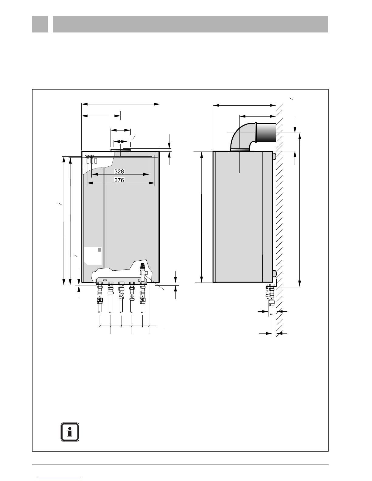
1.1 Dimensions, connections and assembly
480 mm (19")
240 mm (9½")
Ø100 (4")
Ø60 (2 ")
3
8
370 mm (14½")
185 mm (7¼")
105 mm (4 ")
1
8
DHW Hot, DHW Cold / 35 mm (1¼")
CH Flow, CH return, GAS / 50 mm (2")
12.5 mm (½")
950 mm (37½")
850 mm (33½")
1.5 mm ( ")
1
17
845.5 mm (33 ")
1
3
840 mm (33")
GAS
CWDO
65
(2½")65(2½")65(2½")
65
(2½")
65
(2½")
13 mm (½")
CH Flow
DHW Hot
DHW Cold
CH Return
PRV
CH Flow = CH flow Ø22 mm compression fitting
GAS = Gas connection for 24C: Ø22 mm compression fitting
for 11S/19S/24S: R¾"
CH Return = CH return Ø22 mm compression fitting
CWDO = Condensate drain G1" OUTSIDE
DHW Hot = DHW warm out Ø15 mm compression fitting
DHW Cold = DHW cold in Ø15 mm compression fitting
PRV = Pressure relief valve R¾" (¾" - ½"-adapter supplied with boiler)
NOTE
See wall-mounting template for the necessary clearances.
Installation 1
Installation and maintenance instructions for wall-mounted condensing gas boiler 600 - 11S/19S/24S/24C • 02/2006 7
Subject to modifications resulting from technical improvements! Buderus • http://www.buderus-domestic.co.uk
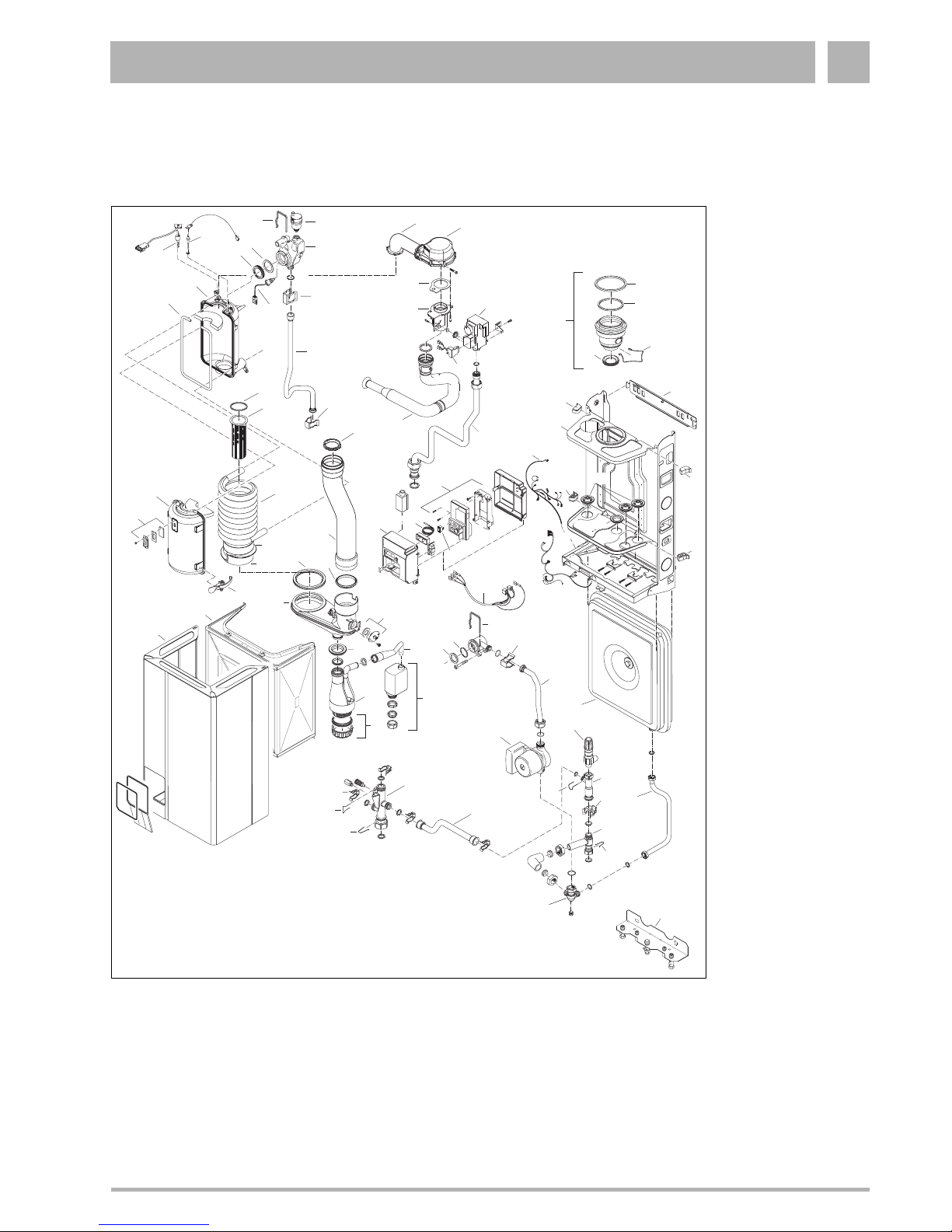
1.2 Boiler assembly - exploded view
Single unit (11S / 19S / 24S)
Legend
1. Flow connection piece
2. Automated air vent
3. Hairpin heat exchanger
4. Flow sensor
5. Clip
6. Flow pipe
7. Clip flow pipe
8. Back part heat exchanger
9. Seal heat exchanger
10. Sealing ring burner
11. Burner
12. Heat exchanger
13. Front panel heat
exchanger
14. Sight glass
15. Fastener
16. Ventilation cover
17. Casing
18. Condensate trap
19. Syphon cap with seal
20. Drain pipe condens. trap
21. Syphon
22. Sealing ring
23. Flue gas sensor
24. Sealing ring
25. Flue gas pipe
26. Flue gas pipe seal
27. Condensate collector
28. Lipring
29. Combustion divider
30. Insulation divider
31. Fan
32. Gas/air supply pipe
33. Fan seal
34. Venturi
35. Gas valve
36. Rectifier
37. Suction pipe
38. Gas pipe
39. Concentric adapter
40. Lip ring
41. Adapter clip
42. Bracket
43. Cable duct
4
0
6
0
8
01
0
0
12
0
C
2
0
0
1
2
3
4
b
a
r
2
3
1
4
5
6
7
8
9
10
11
12
13
14
17
16
15
19
18
20
22
23
24
25
28
27
53
54
32
31
26
29
30
33
34
35
36
37
38
39
40
27
41
28
42
43
43
44
43
43
45
46
47
48
49
50
51
52
3
54
53
5
55
56
57
60
58
59
61
62
63
64
65
66
7
7
7
7
65
68
67
69
82
83
21
44. Ventilation cover seal
45. Pipe duct
46. Sealing ring
47. Cable harness
48. UBA
49. Power switch
50. Temp-pressure gauge
51. UBA panel
52. 230V cable
53. O-ring
54. O-ring
55. Return pump connection pipe
56. Pump
57. Expansion vessel
58. Expansion vessel pipe
59. Manifold assembly
60. Pressure relief valve
61. Spring set
62. Connection house by-pass
63. Clip by-pass
64. Connection house three-way valve
65. Spring set
66. Connection housing pump
67. Connection housing
68. Clip
69. By-pass pipe
82. Hot surface ignitor
83. Ionisation electrode
Installation1
8 Installation and maintenance instructions for wall-mounted condensing gas boiler 600 - 11S/19S/24S/24C • 02/2006
Buderus • http://www.buderus-domestic.co.uk Subject to modifications resulting from technical improvements!
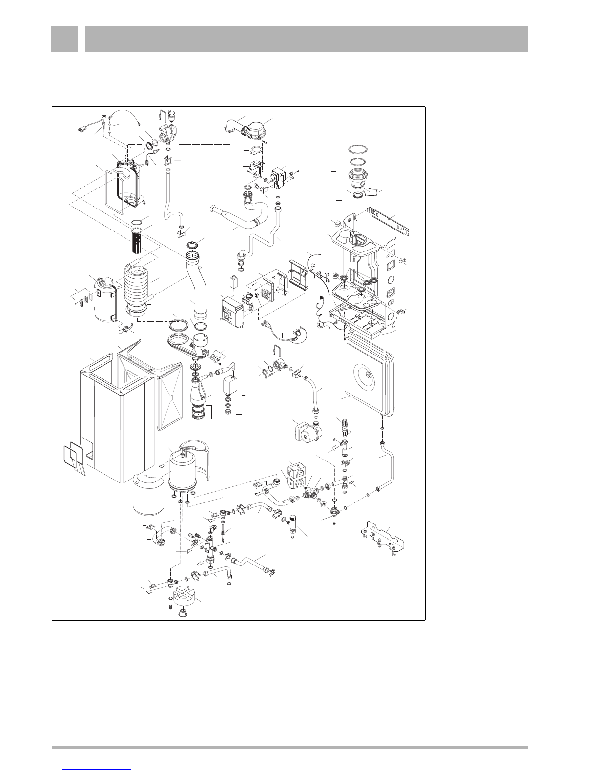
Combi unit (24C)
Legend
1. Flow connection piece
2. Automated air vent
3. Hairpin heat exchanger
4. Flow sensor
5. Clip
6. Flow pipe
7. Clip flow pipe
8. Back part heat exchanger
9. Seal heat exchanger
10. Sealing ring burner
11. Burner
12. Heat exchanger
13. Front panel heat
exchanger
14. Sight glass
15. Fastener
16. Ventilation cover
17. Casing
18. Condensate trap
19. Syphon cap with seal
20. Drain pipe condens. trap
21. Syphon
22. Sealing ring
23. Flue gas sensor
24. Sealing ring
25. Flue gas pipe
26. Flue gas pipe seal
27. Condensate collector
28. Lipring
29. Combustion divider
30. Insulation divider
31. Fan
32. Gas/air supply pipe
33. Fan seal
34. Venturi
35. Gas valve
36. Rectifier
37. Suction pipe
38. Gas pipe
39. Concentric adapter
40. Lip ring
41. Adapter clip
42. Bracket
43. Cable duct
44. Ventilation cover seal
45. Pipe duct
46. Sealing ring
47. Cable harness
48. UBA
49. Power switch
50. Temp-pressure gauge
4
0
6
0
8
01
0
0
1
2
0
C
2
0
0
1
2
3
4
b
a
r
2
3
1
4
5
6
7
8
9
10
11
12
13
14
17
16
15
19
18
20
22
23
24
25
28
27
53
54
32
31
26
29
30
33
34
35
36
37
38
39
40
28
41
28
42
4243
43
44
43
43
45
46
47
48
49
50
51
52
3
54
53
5
55
56
57
60
58
59
61
62
63
64
65
66
7
7
7
65
68
69
77
76
68
7
7
7
68
70
75
67
7
72
71
71
73
71
74
78
80
81
79
83
82
84
21
51. UBA panel
52. 230V cable
53. O-ring
54. O-ring
55. Return pump connection pipe
56. Pump
57. Expansion vessel
58. Expansion vessel pipe
59. Manifold assembly
60. Pressure relief valve
61. Spring set
62. Connection house by-pass
63. Clip by-pass
64. Connection house three-way valve
65. Spring set
66. Connection housing pump
67. Connection housing
68. Clip
69. By-pass pipe
70. DHW pipe (hot)
71. Clip
72. DHW supply pipe
73. Hot water sensor
74. Boiler sensor
75. Insulation hot water tank
76. DHW pipe (cold)
77. Flow regulator
78. Three-way valve body
79. Three-way valve cartridge
80. Three-way valve cover
81. Three-way valve head
82. Hot surface ignitor
83. Ionisation electrode
84. Hot water tank
Installation 1
Installation and maintenance instructions for wall-mounted condensing gas boiler 600 - 11S/19S/24S/24C • 02/2006 9
Subject to modifications resulting from technical improvements! Buderus • http://www.buderus-domestic.co.uk
1.3 Flue Installation
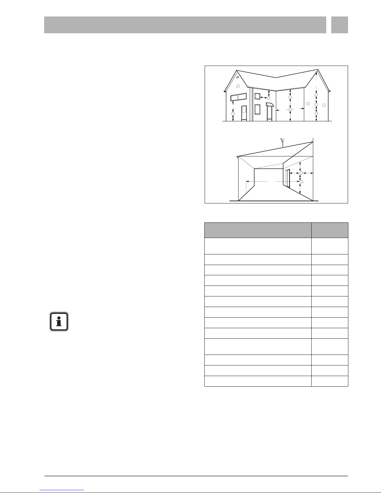
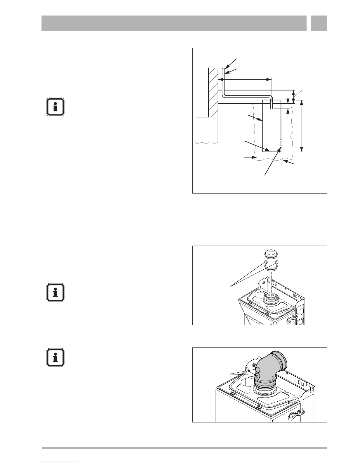
1.3.1 Siting the flue terminal
The flue must be installed in accordance with the
recommendations of BS. 5440-1:2000.
Pluming will occur at the terminal so terminal positions where
this could cause a nuisance should be avoided.
The air supply and the flue gas exhaust must meet the
applicable general regulations. Please consult the instructions
provided with the flue terminal kits prior to installation.
The boiler MUST be installed so that the terminal is exposed
to external air.
It is important that the position of the terminal allows the free
passage of air at all times.
Minimum acceptable spacing from the terminal to obstructions
and ventilation openings are specified in table 1.
If the terminal is fitted within 1000 mm of a plastic or painted
gutter or within 500 mm of painted eaves, an aluminium shield
of at least 1000 mm long should be fitted to the underside of
the gutter or painted surface.
If the lowest part of the terminal is less than 2 metres above the
level of the ground, balcony, flat roof or place to which any
person has access, the terminal must be protected by a guard.
Protective guards are available from Quinnell Barrett and
Quinnell, Old Kent Road, London.
Ensure that the guard is fitted centrally.
The flue assembly shall be so placed or shielded as to prevent
ignition or damage to any part of the building.
The air inlet/products outlet duct and the terminal of the boiler
MUST NOT be closer than 25 mm (1'') to combustible material.
Detailed recommendations on the protection of combustible
material are given in BS. 5440- 1:2000.
If this could occur the appliance MUST be turned off (with the
owners permission), and labelled as unsafe until corrective
action can be taken.
Fig. 1 Flue terminal position
A
A
F
M
G
M
B,C
F
F
B,C
K
G
K
K
G
C
L
L
FJ
K
G
D
H, I
under carport
Terminal Position
Minimum
Spacing
A. Directly below or alongside an opening
window, air vent or other ventilation opening
300 mm (12")
B. Below guttering, drain pipes or soil pipes
75 mm (3")
C. Below eaves
200 mm (8")
D. Below balconies or a car port roof
200 mm (8")
E. From vertical drain pipes or soil pipes
150 mm (6")
F. From internal or external corners
300 mm (12")
G. Above adjacent ground, roof or balcony level
300 mm (12")
H. From a surface facing the terminal
600 mm (24")
I. From a terminal facing a terminal
1200 mm (48")
J. From an opening in a car port (e.g. door or
window) into dwelling
1200 mm (48")
K. Vertically from a terminal on the same wall
1500 mm (60")
L. Horizontally from a terminal on the wall
300 mm (12")
M. Adjacent to opening
300 mm (12")
Table 1 Balanced flue terminal position
NOTE
It is absolutely essential to ensure, in practice,
that products of combustion discharging from
the terminal cannot re-enter the building or any
other adjacent building through ventilators,
windows, doors, other sources of natural
air infiltration, or forced ventilation/airconditioning.
Installation1
10 Installation and maintenance instructions for wall-mounted condensing gas boiler 600 - 11S/19S/24S/24C • 02/2006
Buderus • http://www.buderus-domestic.co.uk Subject to modifications resulting from technical improvements!
1.3.2 Air supply and flue gas exhaust in a closed
installation
A ventilation cover is integrated into the 600 Series condensing
gas boilers. This cover houses a number of components, such
as the burner and the heat exchanger. Since this ventilation
cover is part of the air supply system, it is vital that it is always
installed correctly.
To ensure optimal operation, the 600 Series appliances must
be connected to a Buderus wall-mounted or roof-mounted flue
terminal. These terminals have been developed specifically for
the 600 Series condensing gas boilers and have been
comprehensively tested. The Buderus wall and roof-mounted
flue terminal kits ensure trouble-free operation.
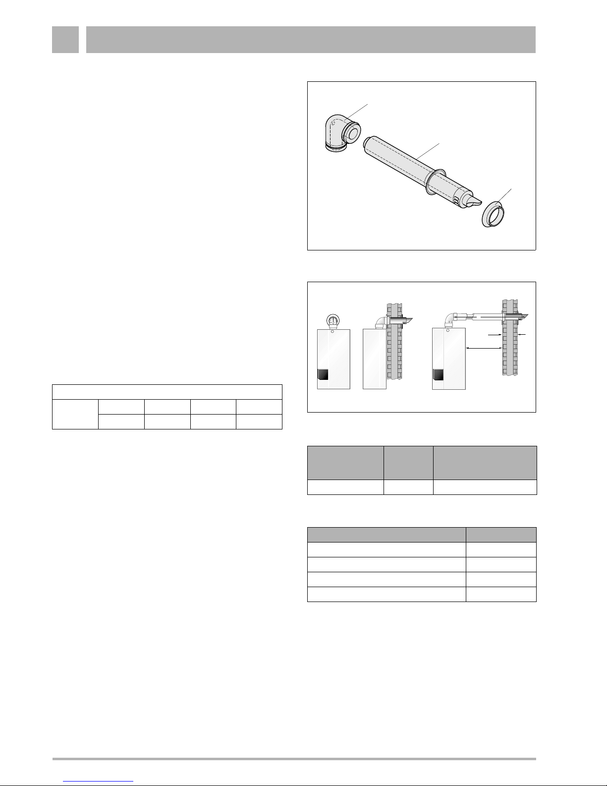
The following items for the flue (see fig. 2) are included in the
delivery of the boiler:
– pos. 1: 1 Concentric bend 60/100;
– pos. 2: 1 Horizontal flue terminal 60/100;
– pos. 3: 1 Flue finishing kit.
1.3.3 Maximum Flue length
The maximum pipe length of the air supply and flue gas
exhaust pipes for the 600 Series condensing gas boilers (see
table 2) is determined by the total pressure loss of all
components in the flue gas exhaust / air supply system.
Take the flue conduit clearances into account when planning
the layout of the place of installation (see subsection 1.3.1:
"Siting the flue terminal" on page 9).
Maximum wall thickness without extensions is 550 mm.
Maintain a minimum side wall clearance of 50 mm (see fig. 3).
1.3.4 Additional flue parts
Additional flue parts (see table 3) can be ordered from your
supplier.
Fig. 2 Horizontal flue pack
1
2
3
Fig. 3 Side flue and rear flue installation
550 mm
50 mm
L
Flow pressure available for use [Pa]
600 Series
11 S 19 S 24 S 24 C
35 60 100 10
Boiler
Maximum
pipe length
For every 90° bend the
maximum pipe length has
to be reduced by
600 Series L = 7.5 m 1.2 m
Table 2 Pipe length
Flue parts Order No.
Concentric pipe, 500 mm long, adjustable NE 83703
Concentric pipe, 1000 mm long, not adjustable NE 83704
Concentric bend 90° NE 83705
Concentric bend 45° NE 83706
Table 3 Additional flue parts
Installation 1
Installation and maintenance instructions for wall-mounted condensing gas boiler 600 - 11S/19S/24S/24C • 02/2006 11
Subject to modifications resulting from technical improvements! Buderus • http://www.buderus-domestic.co.uk
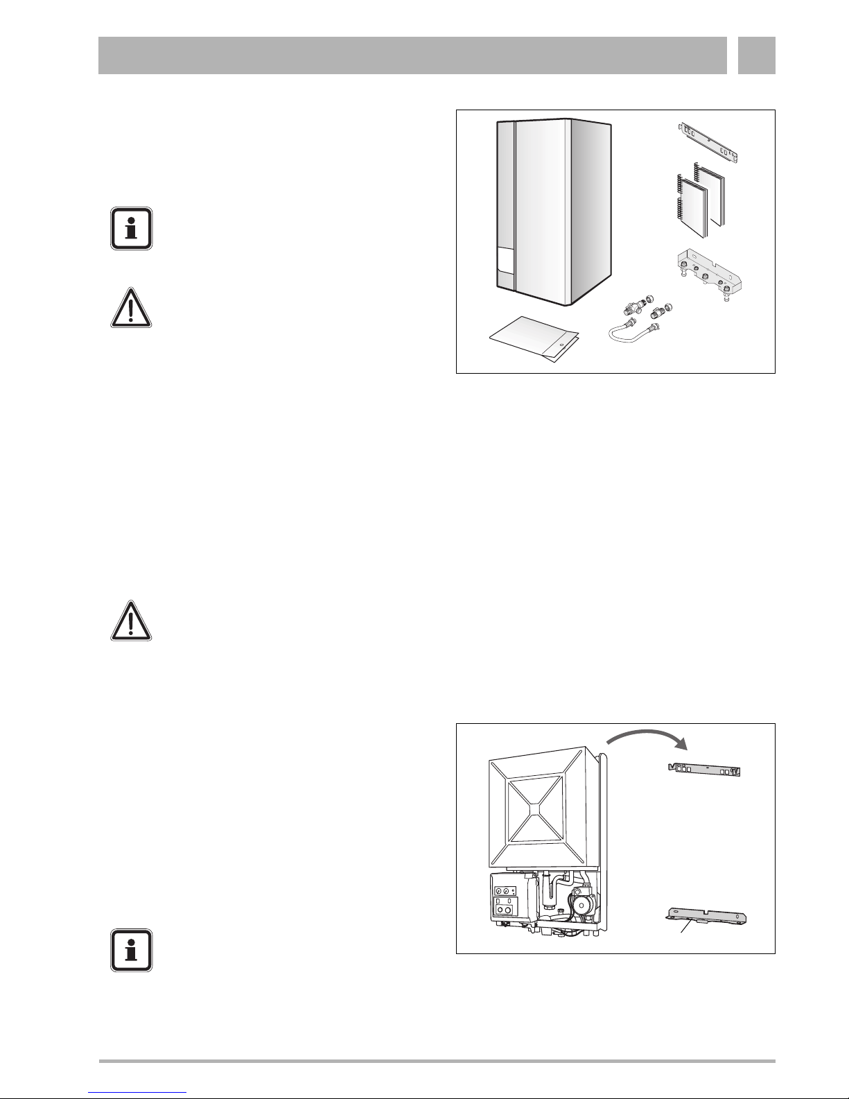
1.4 Items supplied with unit
z Check the contents against the packing list to ensure that
nothing is missing.
Requirements to be met by the place of installation
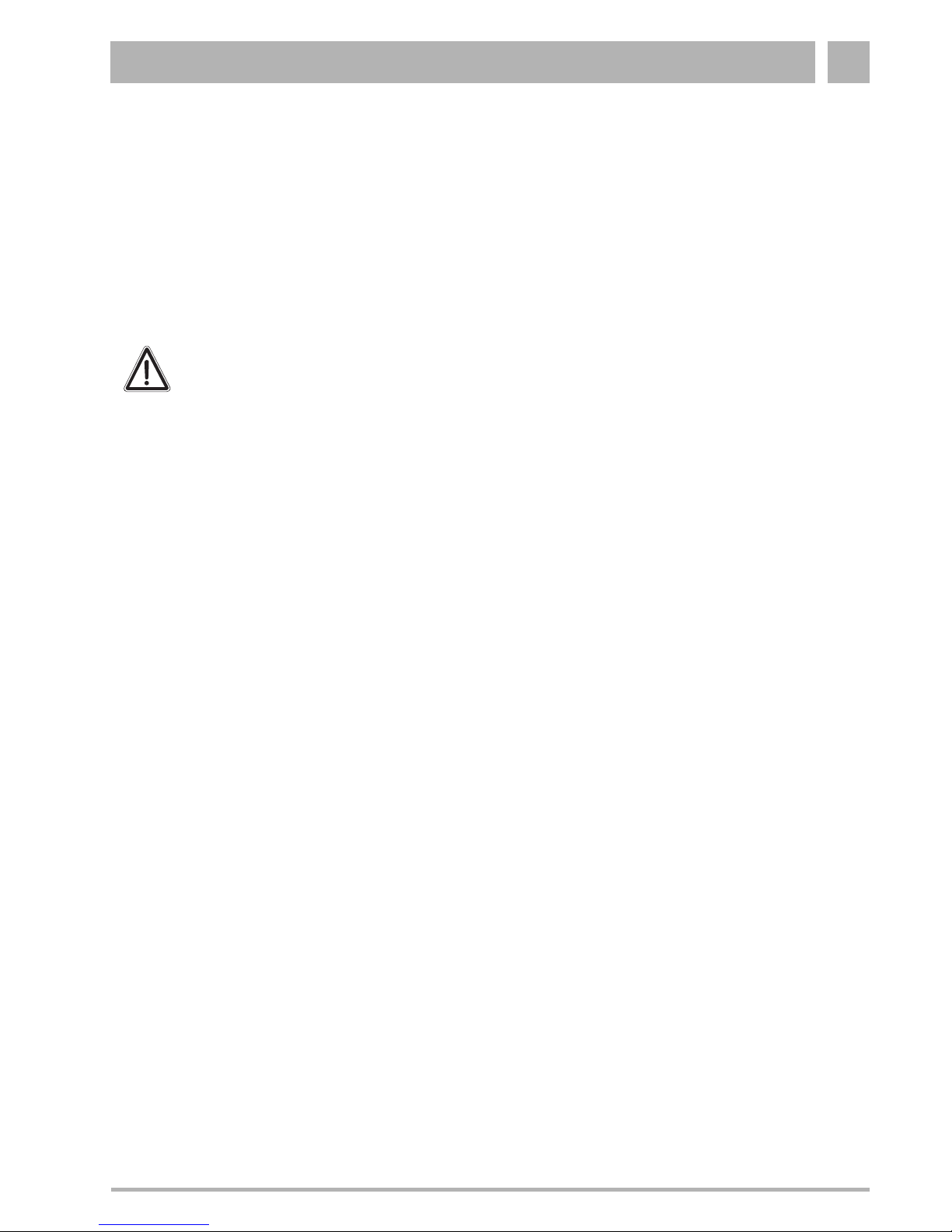
1.5 Hanging the boiler
z Attach the manifold assembly to the wall (see fig. 5,
item 1).
z Attach the pipes.
z Attach the wall bracket.
z When using a stand-off frame, refer to the manual of the
stand-off frame for the correct mounting instructions.
z Loosen the retaining screw on the bottom of the
condensing gas boiler.
z Detach the outer casing of the condensing gas boiler.
z Hang the condensing gas boiler onto the wall bracket
(fig. 5).
Fig. 4 Items supplied with unit
Key to fig. 4:
1: Wall-mounted condensing gas boiler
2: Wall bracket
3: Technical documents
4: Manifold assembly
5: Filling loop
6: Plastic bag containing the following accessories:
4 x wall fixing-screws
4 x wall plugs
4 x washers
Seals (1 x 1“, 2 x ¾“, 2 x ½“)
Square wrench
Initial start-up sticker
Second identification plate
Safety valve nipple (from ¾“ to ½“)
4
1
2
3
6
5
NOTE
Observe all statutory building regulations
applying to the place of installation.
DANGER!
Inflammable materials or liquids must not be
stored or used near wall-mounted condensing
gas boilers. The site of installation must be
frost-protected.
CAUTION
DO NOT remove the polystyrene foam bottom
slab protecting the connection nozzles.
During installation work, cover the wallmounted condensing gas boiler and the flue
gas adapter to prevent site dirt from entering,
e. g. using aluminium foil.
Fig. 5 Installation
1
NOTE
If the boiler isn't connected to the pipework
immediately, place caps on the pipe
connections.

Installation1
12 Installation and maintenance instructions for wall-mounted condensing gas boiler 600 - 11S/19S/24S/24C • 02/2006
Buderus • http://www.buderus-domestic.co.uk Subject to modifications resulting from technical improvements!
1.6 Water circulation system
The central heating system should be in accordance with
BS.6798 and, in addition, for smallbore and microbore
systems, BS.5449.
1.7 Pipe connections
Pipework from the boiler is routed downwards as standard, but
may be routed upwards behind the boiler using the stand-off
frame (supplied in a separate kit).
z Connect pipes as shown in fig. 6. Ensure that all pipework
is routed so as to minimise any strain on the boiler fittings.
1.7.1 Gas Supply
The gas installation must be installed in accordance with
BS6891.
The complete installation MUST be tested for gas tightness
and purged as described in IGE/UP/1b.
1.7.2 Gas connection
z Connect to gas supply according to relevant standards,
installing a screw-threaded gas shutoff valve (accessory)
to the gas supply system.
1.7.3 Hot-water temperature for 600 - 24C
z Fit a non-shutting diaphragm safety valve (max. 8 bar)
upstream of the cold-water inlet. This is not required if the
building is equipped with a pressure regulator configured to
guarantee that the maximum supply pressure of 10 bar
cannot be exceeded.
z Connect pipes free of tension (fig. 6).
Fig. 6 Pipe connections
Key to fig. 6:
1: CH flow
2: DHW warm out (combi only)
3: Gas
4: DHW cold in (combi only)
5: CH return
6: Condensate trap
123
4
5
6
CAUTION!
Pipework from the meter to the boiler MUST be
of adequate size.
CAUTION
DO NOT use galvanised pipes or fittings.
The hot water heat exchanger is made of
copper and is liable to suffer the effects of
electrolytic corrosion.
NOTE
When using plastic pipes, observe the
supplier’s instructions especially those
referring to recommended jointing techniques
and the notes relating to the heating system
water on page 5.
Installation 1
Installation and maintenance instructions for wall-mounted condensing gas boiler 600 - 11S/19S/24S/24C • 02/2006 13
Subject to modifications resulting from technical improvements! Buderus • http://www.buderus-domestic.co.uk
1.7.4 Condensate drain
A condensate drain is integrated in the boiler. The drain outlet
is a standard G1" outside connection. This drain needs to be
connected to a drainage point. All pipework and fittings in the
condensate drainage system MUST be made of plastic - no
other materials may be used.
The routing of the drain must be made to allow a minimum fall
of 1 in 20 away from the boiler, throughout its length.
Excessive external pipe runs should be avoided in order to
prevent possible freezing.
Any external pipework should be a minimum of 32 mm internal
diameter.
Ensure that the condensate trap is filled with water.
1.7.5 Condensate removal
Positioning and termination of the condensate drain pipe
The condensate pipe should be run and terminate internally to
the house soil and vent stack or waste pipe. Alternatively, the
condensate can be discharged into the rainwater system, or
into a purpose-made soak away (condensate absorption
point).
All connecting drainage pipework should have a fall of at least
2.5° to the horizontal, or approximately 50 mm per metre of
pipe run.
If the drainage pipe has to be run externally, it is recommended
that the pipe be insulated to protect against frost.
It should be noted that the connection of a condensate pipe to
a drain may be subject to local building controls.
Material for condensate
The condensate drainage pipe should be run in a standard
drain pipe material, e.g. PVC (polyvinyl chloride), PVC-U
(unplasticized polyvinyl chloride), BS (acrylonitrilebutadienestyrene), PP (polypropylene polyprolene) or PVC-C
(cross-linked polyvinyl chloride).
WARNING!
Any external run must be insulated.
Installation1
14 Installation and maintenance instructions for wall-mounted condensing gas boiler 600 - 11S/19S/24S/24C • 02/2006
Buderus • http://www.buderus-domestic.co.uk Subject to modifications resulting from technical improvements!
Any internal pipework should be of a diameter to match the
requirements of the condensate exit pipe on the appliance.
A 32 mm (1¼") waste pipe solvent weld fitting can be used,
fitted externally over the condensate exit pipe on the
appliance.
All external pipework should be kept to a minimum to avoid
freezing and should have a diameter of not less than 22 mm.
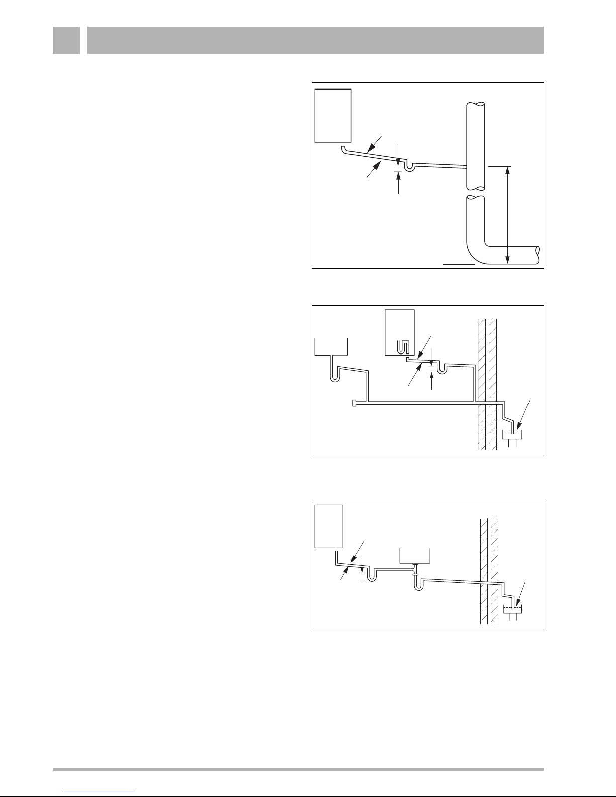
Internal termination to internal stack
The condensate drainage pipe should have a minimum
diameter of 1" with no length restriction. It should incorporate
a trap with a 75 mm condensate seal and be connected to the
stack at a point at least 450 mm above the invert of the stack.
The trap built into the boiler will provide this 75 mm condensate
seal. For all internal and external stack connections a second
trap is required to prevent any odours emanating from the
condensate air break at the boiler (see fig. 7).
External termination via internal branch (e.g. sink waste)
The condensate drainage pipe should have a minimum
diameter of 1" with no length restriction and should incorporate
a trap with a 75 mm seal. The connection should preferably be
made downstream of the sink waste trap. If the connection is
only possible upstream, then the air break is needed between
the two traps. This is normally provided by the sink waste pipe
(see fig. 8 and fig. 9).
Fig. 7 Internal termination of condensate drainage pipe to
internal stack
No length restriction
Ø22 mm min.
75 mm min. trap
internal soil
and vent stack
invert
Boiler
450 mm min.
Fig. 8 External termination of condensate drainage pipe
via internal discharge branch (e.g. sink waste) and
condensate syphon
75 mm min. trap
No length restriction
Ø22 mm min.
Open end of pipe
direct into gully,
below ground but
above water level
Boiler
Sink
Fig. 9 External termination of condensate drainage pipe
via internal discharge branch (e.g. sink waste –
proprietary fitting) and condensate syphon
No length
restriction
Boiler
Open end of pipe
direct into gully,
below ground but
above water level
75 mm min. trap
Ø22 mm min.
Sink
Installation 1
Installation and maintenance instructions for wall-mounted condensing gas boiler 600 - 11S/19S/24S/24C • 02/2006 15
Subject to modifications resulting from technical improvements! Buderus • http://www.buderus-domestic.co.uk
Condensate absorption point
The condensate drainage pipe should have a minimum
diameter of 1" and the external pipe length should not be more
than 3 m. The condensate absorption point should be sited in
a convenient position as close as possible to the boiler but not
in the vicinity of other services.
See fig. 10 for information.
1.8 Flue installation
The only flue systems that may be used are those supplied by
Buderus. The flue system must be installed in accordance with
the requirements of BS5440:1. 2000.
Standard 100 mm flue systems
The standard concentric flue system provides for a max.
horizontal straight length of upto 7.5 m (see subsection 1.3.3).
Full instructions for fitting this flue are in subsection 1.8.2:
"Installation of the horizontal flue" on page 16.
1.8.1 Connecting the vertical flue gas duct
z Fit the vertical flue gas duct (fig. 11) onto the appliance flue
connector.
z For remaining installation of the vertical flue assembly,
refer to the relevant installation instructions.
Fig. 10 External termination of condensate drainage pipe to
absorption point
Ø100 mm min.
plastic tube
bottom of
tube sealed
limestone
cladding
hole depth
400 mm min.
300 mm min.
25 mm min.
Ground
(either/or)
Two rows of three
12 mm holes at 25 mm centres
50 mm from bottom of tube and
facing away from house
1000 mm min.
Ø22 mm min.
External length of
pipe 3m max.
NOTE
When discharging condensate to an outside
drain caution must be taken to ensure
blockage cannot occur during freezing
conditions. If this is likely to occur, the use of a
syphon trap is recommended.
Fig. 11 Vertical flue connection
Flue gas
testing point
IMPORTANT
Any horizontal flue system fitted to a
condensing boiler must be incline towards the
appliance at an angle of 3% (30 mm per metre
length) to prevent condensate dripping from
the flue terminal.
This means that the clearance above the
appliance must be increased to match the duct
length. See figure on page 6.
Fig. 12 Elbow with flue gas testing point
Flue gas
testing point
NOTE
When using a stand-off frame, don’t forget to
take its measurements into account when
designing a flue system.
Installation1
16 Installation and maintenance instructions for wall-mounted condensing gas boiler 600 - 11S/19S/24S/24C • 02/2006
Buderus • http://www.buderus-domestic.co.uk Subject to modifications resulting from technical improvements!
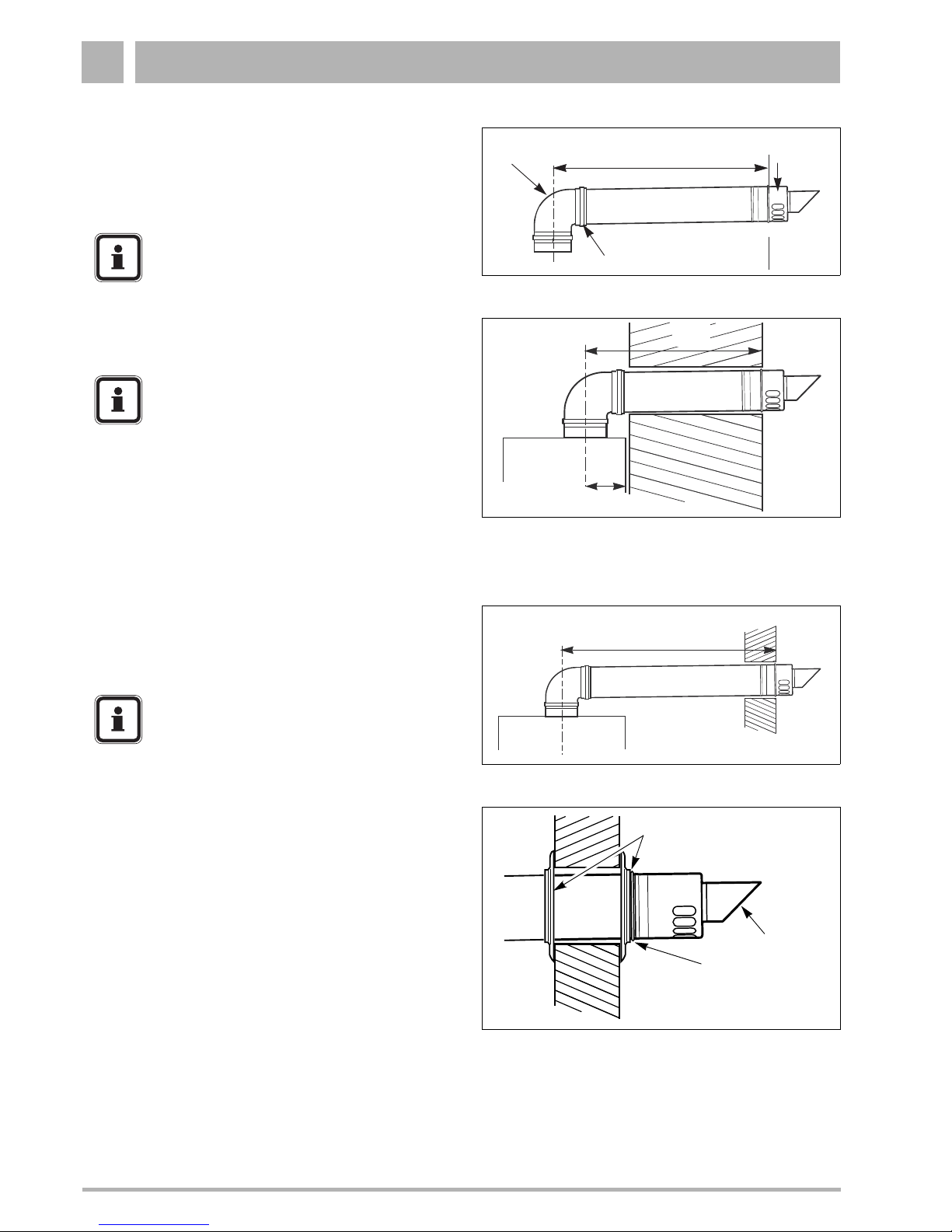
1.8.2 Installation of the horizontal flue
The standard 100 mm diameter horizontal flue system is
suitable for lengths upto 560 mm (see fig. 13).
For longer flue runs upto 7.5 m, extension air/flue ducts are
available (see page 10, table 3).
1.8.3 Flue duct preparation and assembly
z Measure the flue length L. Refer to figures 14 and 15.
z Mark of the lengths shown onto the ducts and cut the
length. The cuts must be square and free from burrs.
Terminal assembly outer (air) duct - L-70 mm, inner (flue)
duct - L-50 mm. The measurement is made from the ridge
at the terminal indicating the outer face of the wall.
Refer to figure 16.
Extension air duct - L-70 mm, flue duct - L-50 mm.
The measurement is from the formed end.
z Assemble flue system completely. Push the ducts fully
together. The slope of the terminal outlet must be face
downwards.
The assembly will be made easier if a solvent free grease
is lightly applied to the male end of the ducts.
z Push the assembly through the wall and slide the turret
onto the flue connector. Refer to figure 12.
z Ensure that the turret is fully entered into the socket on the
boiler. From the outside fix the flue finishing kit to the
terminal and, after ensuring the duct is properly inclined
towards the boiler, fix the finishing kit to the wall.
If the terminal is within 2 m of the ground where there is
access then an approved terminal guard must be fitted.
The guard must give a clearance of at least 50 mm around
the terminal and be fixed with corrosion resistant screws.
Fig. 13 Standard flue
Flue
Turret
No Clamp
Maximum 560 mm
Terminal
assembly
Outer
Wall
NOTE
Use the wall-mounting template to help you
mark the position of the side flue opening
Fig. 14 Flue length - rear
185
L
NOTE
The flue must be inclined to the boiler.
Fig. 15 Flue length - side
L
NOTE
An inner wall sealing plate is provided which
should be fitted to the ducts before assembly.
Fig. 16 Flue terminal position
Outer
Wall
Face
Flue Finishing Kit
Flue Terminal
Raised Ring
locating the
terminal relative
to the outside
wall face
Installation 1
Installation and maintenance instructions for wall-mounted condensing gas boiler 600 - 11S/19S/24S/24C • 02/2006 17
Subject to modifications resulting from technical improvements! Buderus • http://www.buderus-domestic.co.uk
1.9 Electrical connections
1.9.1 Mains connection
A mains supply of 230 V - 50Hz is required.
External controls are suitable for volt free or 230 V installation.
Wiring to the boiler MUST be in accordance with the current
I.E.E. (BS.7671) Wiring Regulations and any local regulations.
Wiring should be a 3 core PVC insulated cable, not less than
0.75 mm
2
(24 x 0.2 mm), and to BS.6500 Table 16.
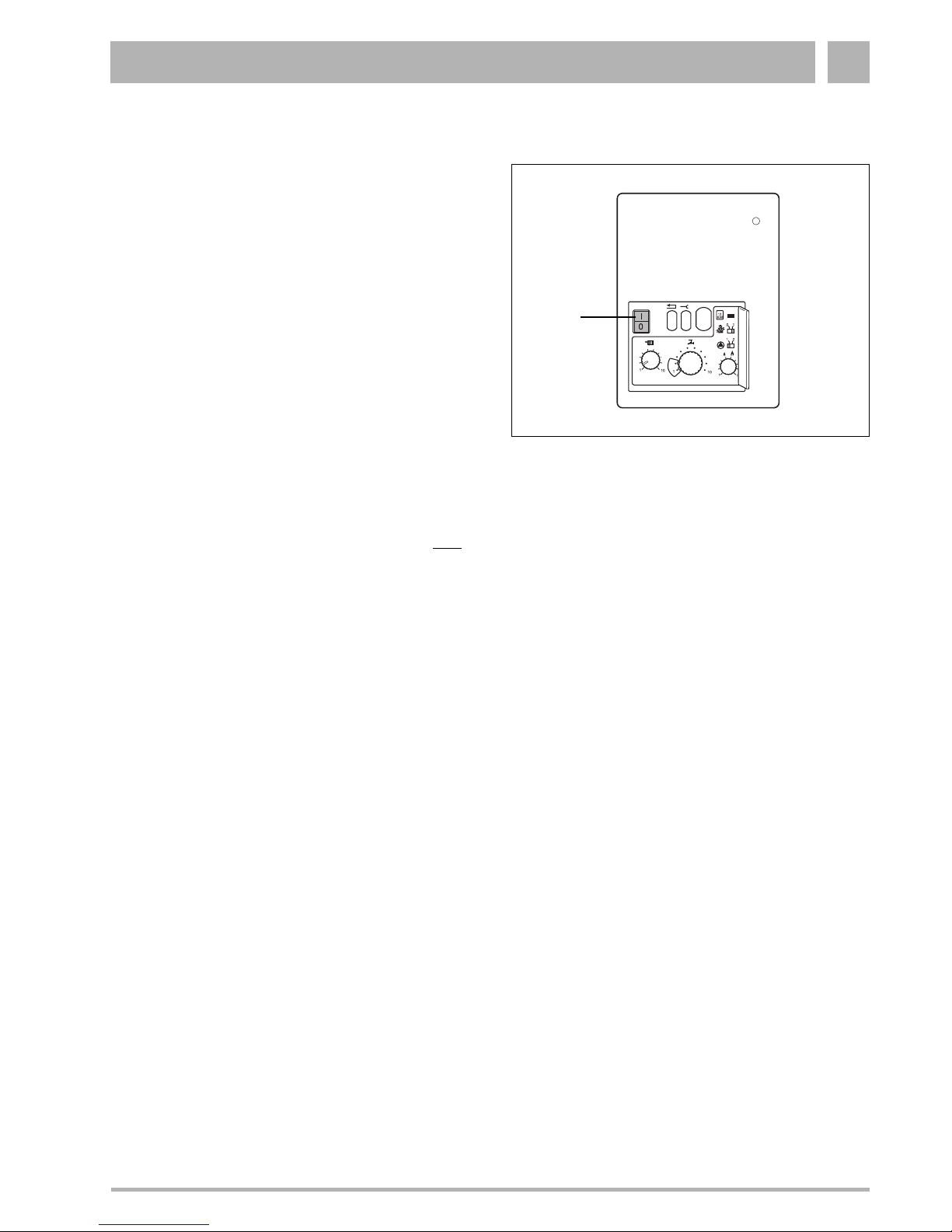
Connection must be made in a way that allows complete
isolation of the electrical supply such as a double pole switch
having 3 mm (1/8'') contact separation in both poles, or a plug
and socket, serving only the boiler and system controls. This
boiler is equipped with a double pole switch see fig. 17, item 1.
The means of isolation must be accessible to the user after
installation.
The electrical connection to the mains supply should be readily
accessible and adjacent to the boiler.
If the supply cord is damaged, it must be replaced by a
registered Corgi installer to avoid a hazard.
The electrical supply for both the boiler and the system must
be taken from the same sparred fused spur outlet.
Fig. 17 UBA
1
Installation1
18 Installation and maintenance instructions for wall-mounted condensing gas boiler 600 - 11S/19S/24S/24C • 02/2006
Buderus • http://www.buderus-domestic.co.uk Subject to modifications resulting from technical improvements!
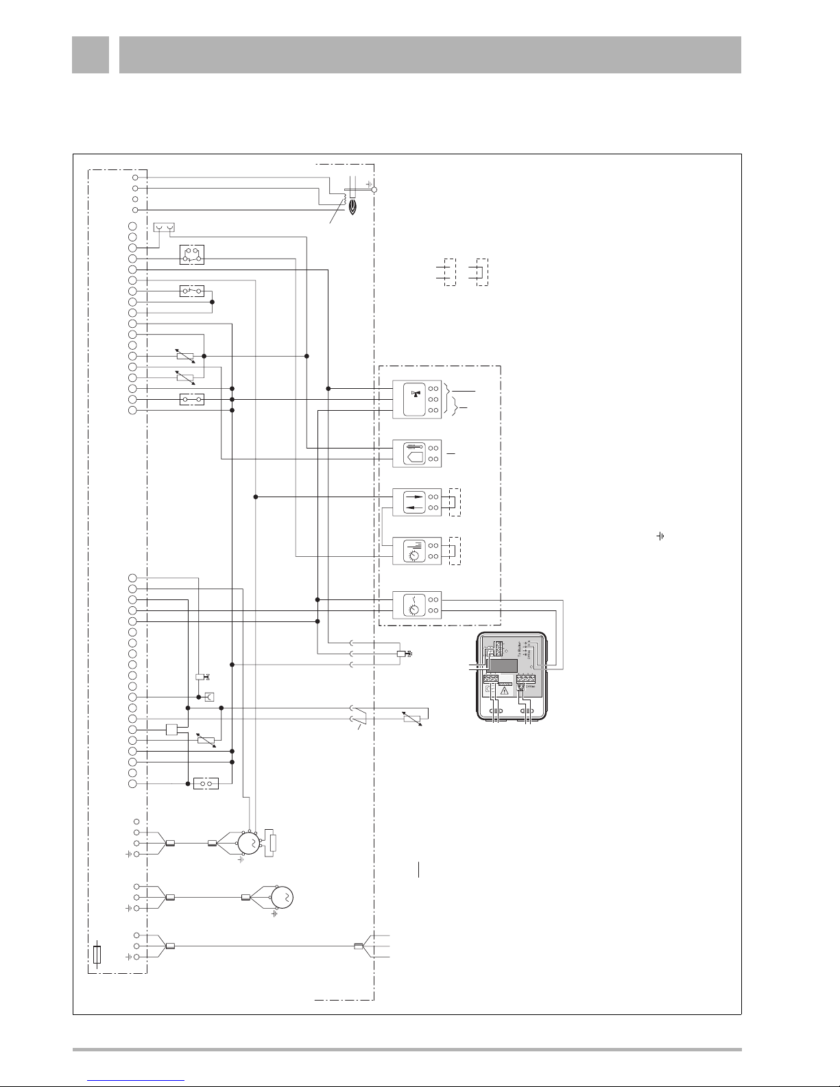
1.10 Wiring Diagram
24 VAC
0 VAC
0
max. 6 VA
hot surface
ignitor
remove bridge when
carrying out connection
Loop is non-conducting
(remove when connecting)
12
M
N
L
12
1234
123
M
N
L
Burner-control unit (UBA)
1 2 3 4 5 6 7 8 91011121314151617181920 1 2 3 4 5 6 7 8 9 10 11 12 13 14 15 16 17 18
20-pin connection strip 18-pin connection strip
12 34 56 78 9 1110
I/O
communication port
24V output (AC)
turn-on voltage for external,
customer-supplied three-way
reversing valve (AC operation)
external sensor
Fuse, main switch, emergency OFF switches and
safety measures to comply with local regulations and standards
circulation pump (PH)
(max. 2A)
STB
MV
HT1
HT2
24Vdc
Ventilator
PA
FR
FS
external three-way
reversing valve for
mains water
(AC operation)
FW
FK
flame-monitoring electrode
Note:
KIM
STK
STK
PA Volt-free connection (bridge connector)
STB Flue gas monitor
FW Domestic hot water temperature sensor
FR Return-temperature sensor (return)
FS Safety-temperature sensor (safety)
FK Boiler water-temperature sensor (supply)
KIM Boiler identification module
MV Solenoid valve
STK Plug socket for additional equipment
HT Hand-held terminal
1) Only one room-temperature regulating
device may be connected.
Mains power source
230V
~
50 Hz
Max. permitted
fuse rating
10A
Bridge is conductive
(remove when connecting)
UBA terminal box
1.25 Ampere slow blow
21
2
1
1
2
12
external
230V controls
Volt free external
control device
*) remove wirebridge
when used
Volt free room
thermostat
when used with
230V timer *)
Connection box
(RTH converter)
1)
IMPORTANT
The wires in this mains lead are coloured in accordance with the following code:
GREEN AND YELLOW - EARTH ; BLUE - NEUTRAL ; BROWN - LIVE
As the colours of the wires in the mains lead of of the appliance may not correspond with the coloured markings identifying the terminals in your connector proceed as follows:
The wire coloured green and yellow must be connected to the terminal on the connector marked with the letter E or by the earth symbol or coloured green or green-and-yellow. The wire coloured brown must be connected to the terminal marked
with the letter L or coloured red. The wire coloured blue must be connected to the terminal marked with the letter N or coloured black.
WARNING
THIS APPLIANCE MUST BE EARTHED
Ensure that your appliance is connected correctly - if you are in any doubt consult a qualified electrician.
For location of individual components, see service section and the exploded views in this manual.
Installation 1
Installation and maintenance instructions for wall-mounted condensing gas boiler 600 - 11S/19S/24S/24C • 02/2006 19
Subject to modifications resulting from technical improvements! Buderus • http://www.buderus-domestic.co.uk
1.10.1 External controls
The wall-mounted condensing gas boiler can be fitted with the
following control devices:
– ON/OFF temperature controller, volt free;
– A room-temperature control device at 230V connected to
the connection plate (fig. 20, item 1).
– A modulating room-temperature control device at 24 Volt
connected to the connection plate (fig. 22, item 1) such as
the 250 RF ModuLink and the
iRT controllers.
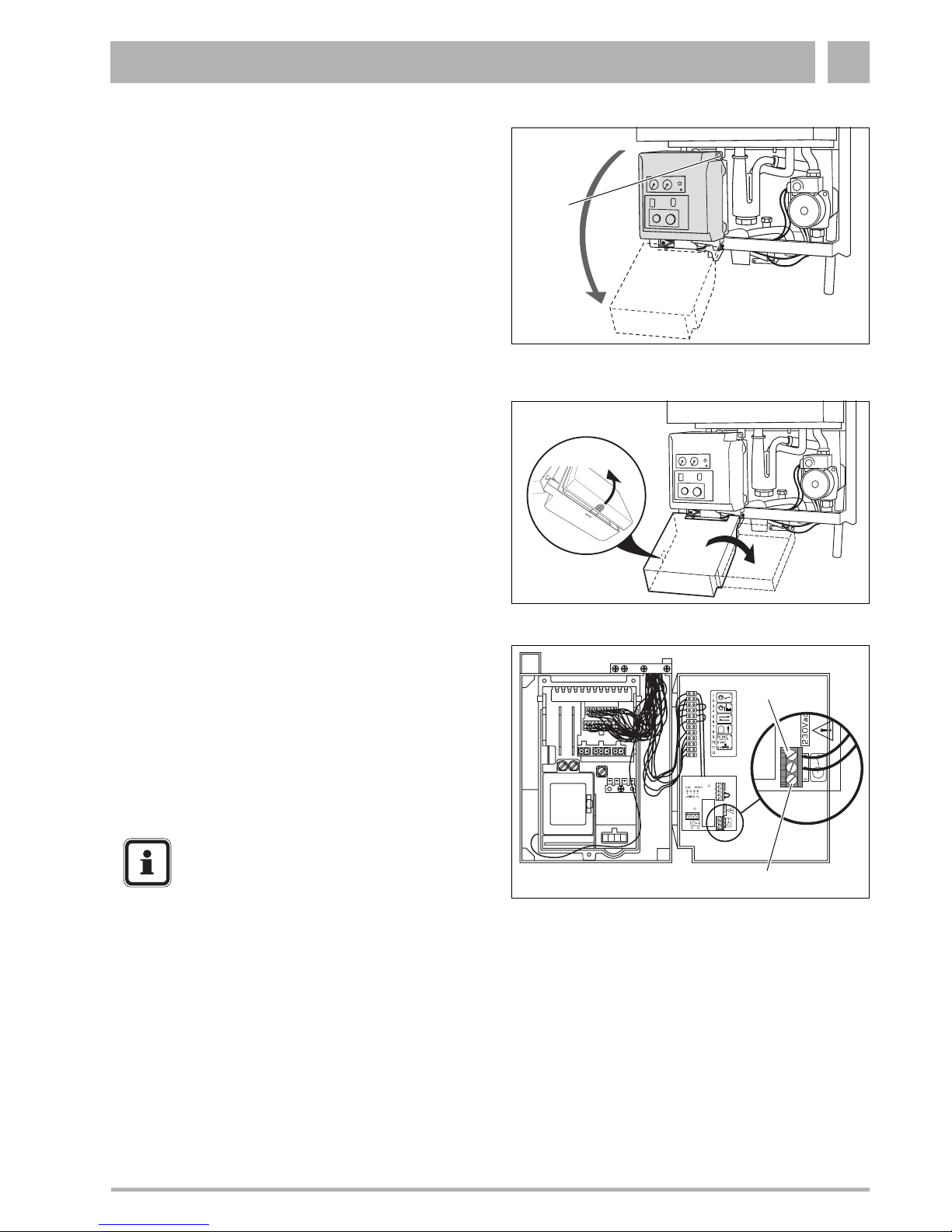
1.10.2 External 230V controls
z Loosen crosshead screw (fig. 18, item 1) on burner-control
unit (UBA).
z Swivel burner-control unit downwards.
z Open the back of the burner-control unit to the right
(fig. 19).
z Connect the black pre-wired lead to a permanent live
supply (from the same fused isolator as all other controls
on the heating system), L N E.
z Feed the 230V switch live and neutral (from external
controls) through the cable lead.
z Identify the 230V terminal block by the shaded area and
230V label.
z Connect the switch live to terminal "1" and a neutral to
terminal "2" (fig. 20, item 1).
z Replace covers.
Fig. 18 Swivel the housing of the burner-control unit
downwards
1
Fig. 19 Open back of the burner-control unit
Fig. 20 Connection box in burner-control unit -
230V connection
1
2
NOTE
Terminal 3 (fig. 20, item 2) is not used.
Installation1
20 Installation and maintenance instructions for wall-mounted condensing gas boiler 600 - 11S/19S/24S/24C • 02/2006
Buderus • http://www.buderus-domestic.co.uk Subject to modifications resulting from technical improvements!
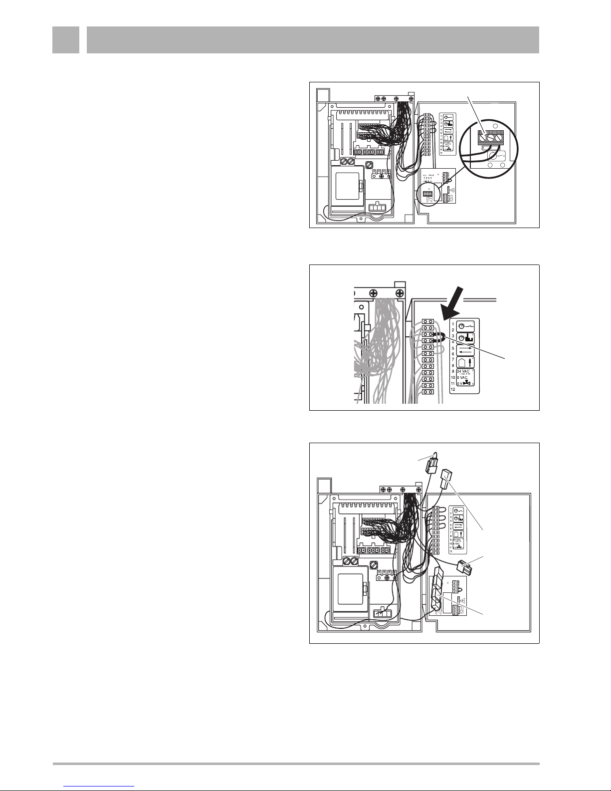
1.10.3 Volt free external control device connection
z Connect the black pre-wired lead to a permanent live
supply (from the same fused isolator as all other controls
on the heating system), L N E.
z Loosen crosshead screw (fig. 18, item 1) on burner-control
unit (UBA).
z Swivel burner-control unit downwards.
z Open the back of the burner-control unit to the right
(fig. 19).
z Lead the control device wire through the cable lead.
z Fix the wire to terminal 1 and 2 of the volt free connection
(fig. 21, item 1).
1.10.4 24 Volt modulating room-temperature control
device connection
z Loosen crosshead screw (fig. 18, item 1) on burner-control
unit (UBA).
z Swivel burner-control unit downwards.
z Open the back of the burner-control unit to the right
(fig. 19).
z Connect the 24 Volt modulating room-temperature control
device at fig. 22, item 1 on pin 3 and 4.
1.10.5 Other connections
Connection of an external water tank for single devices
600 - 11S/19S/24S:
z Remove bridge (fig. 23, item 1).
z Connect sensor for external water tank.
Connection for a second LPG solenoid valve:
z Connect switch unit for a second solenoid valve
(accessory) at green plug (fig. 23, item 2).
Connection of a modulating pump:
z Connect modulating pump (accessory) at plug (fig. 23,
item 3).
Connection of an external switch contact for underfloor
heating system:
z Open plug (fig. 23, item 4) connection.
z Connect underfloor heating header thermostat (volt free)
and in series.
Fig. 21 Connection box in burner-control unit -
volt free connection
1
Fig. 22 Connection box in burner-control unit -
24 Volt connection
1
Fig. 23 Other connections
1
2
3
4
Installation 1
Installation and maintenance instructions for wall-mounted condensing gas boiler 600 - 11S/19S/24S/24C • 02/2006 21
Subject to modifications resulting from technical improvements! Buderus • http://www.buderus-domestic.co.uk
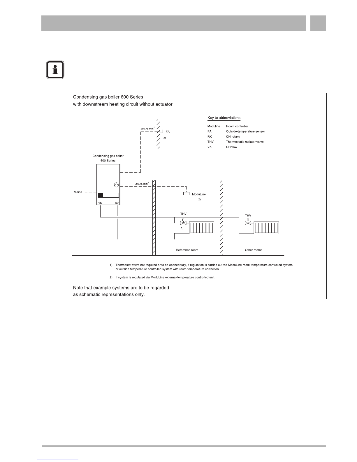
1.10.6 System example
NOTE
Example systems are to be regarded as
schematic representations only.
Fig. 24 System example
Initial start-up2
22 Installation and maintenance instructions for wall-mounted condensing gas boiler 600 - 11S/19S/24S/24C • 02/2006
Buderus • http://www.buderus-domestic.co.uk Subject to modifications resulting from technical improvements!
2 Initial start-up
2.1 Preparing the boiler for operation
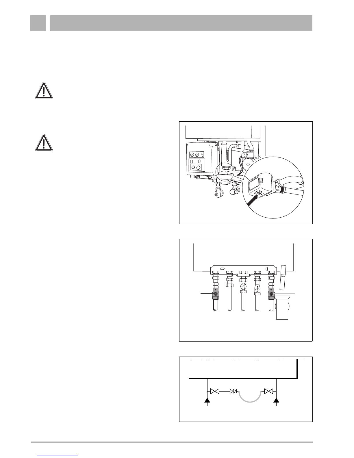
2.1.1 Fill the heating system
z Set three-way valve to the middle setting (applicable for
24C only). This is done by pushing the lever on the threeway valve (fig. 25) with a screwdriver to the middle setting.
z If necessary open the CH flow and CH return maintenance
valves (fig. 26, item 1 and 2).
z Connect temporary hose (fig. 27).
z Open both stop valves.
CAUTION
DO NOT operate the condensing gas boiler if
large amounts of dust are present, e.g. due to
building work in and around the place of
installation.
Fig. 25 Three-way valve
WARNING
The wall-mounted condensing gas boiler must
not be activated at this stage.
Fig. 26 Maintenance shutoff valves
CH Flow
CH Return
DHW Hot
(combi only)
DHW Cold
(combi only)
Gas
1
2
Fig. 27 Connecting temporary hose
temporary
hose
stop
valve
stop
valve
double
check
valve
DHW
cold
CH
return
 Loading...