

Buderus 600-19R, 600-11R, 600-24R, 600 Series, 11R Installation And Servicing Instructions
...Page 1
7212 2900 - 05/2004 GB(EN) For trade use
Installation and servicing
instructions
Wall-mounted condensing gas boiler
Buderus 600 - 11R / 19R / 24R
Please read thoroughly before installing or servicing
Page 2
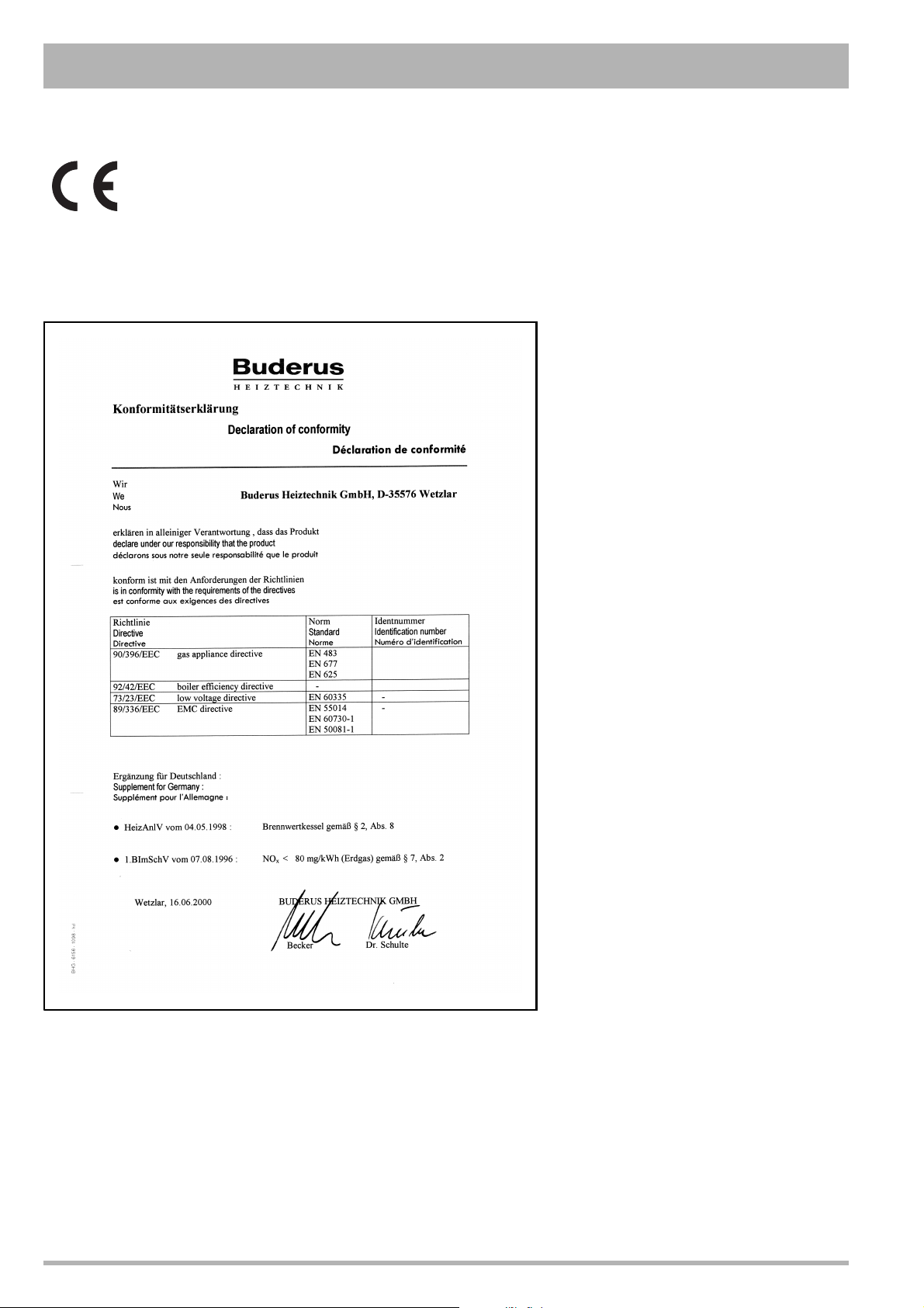
The boiler meets the basic requirements of the
appropriate standards and directives.
Conformity has been substantiated by the proper
documents which - together with the declaration of
conformity - are filed with the manufacturer.
Buderus 600 Series
CE-0063BO3062
CE-0063BO3062
Subject to technical modifications!
Constant development efforts may result in minor deviations in
illustrations, functional steps and technical data.
Updating the documentation
If you have suggestions for improvement or have found
discrepancies, please do not hesitate to contact us.
Subject to modifications resulting from technical improvements! Boulter Buderus Ltd. • http://www.boulter-buderus.co.uk
2 Installation and servicing instructions for wall-mounted condensing gas boiler Buderus 600 - 11R/19R/24R • 05/2004
Page 3

Contents
1 Installation . . . . . . . . . . . . . . . . . . . . . . . . . . . . . . 9
1.1 Dimensions and connections . . . . . . . . . . . . . . . . . 9
1.2 Boiler assembly - exploded view . . . . . . . . . . . . . 10
1.3 Flue Installation . . . . . . . . . . . . . . . . . . . . . . . . . . 11
1.4 Items supplied with unit . . . . . . . . . . . . . . . . . . . . 13
1.5 Transport . . . . . . . . . . . . . . . . . . . . . . . . . . . . . . . 13
1.6 Pipe connections . . . . . . . . . . . . . . . . . . . . . . . . . 14
1.7 Flue installation . . . . . . . . . . . . . . . . . . . . . . . . . . 15
1.8 Electrical connections. . . . . . . . . . . . . . . . . . . . . . 17
1.9 Timing and temperature control . . . . . . . . . . . . . . 19
2 Initial start-up . . . . . . . . . . . . . . . . . . . . . . . . . . . 20
2.1 Preparing the boiler for operation. . . . . . . . . . . . . 20
3 Inspection . . . . . . . . . . . . . . . . . . . . . . . . . . . . . . 26
3.1 Preparing the heating boiler for inspection . . . . . . 26
4 Maintenance . . . . . . . . . . . . . . . . . . . . . . . . . . . . 27
4.1 Clean the heat exchanger, burner and
condensate trap . . . . . . . . . . . . . . . . . . . . . . . . . . 27
5 Servicing . . . . . . . . . . . . . . . . . . . . . . . . . . . . . . . 31
5.1 Operating codes . . . . . . . . . . . . . . . . . . . . . . . . . . 31
5.2 Fault codes. . . . . . . . . . . . . . . . . . . . . . . . . . . . . . 32
5.3 Checking and replacing parts. . . . . . . . . . . . . . . . 40
6 Conversion to another type of gas. . . . . . . . . . 48
7 Appendix . . . . . . . . . . . . . . . . . . . . . . . . . . . . . . . 50
7.1 Technical specifications . . . . . . . . . . . . . . . . . . . . 50
7.2 Short list of spare parts . . . . . . . . . . . . . . . . . . . . 52
8 Reports . . . . . . . . . . . . . . . . . . . . . . . . . . . . . . . . 53
8.1 Start-up report . . . . . . . . . . . . . . . . . . . . . . . . . . . 53
8.2 Inspection and maintenance reports . . . . . . . . . . 54
Preface
These installation and servicing instructions apply to:
Buderus wall-mounted condensing gas boilers
600 - 11R / 19R / 24R.
Model: C13, C33, C
Type: GB II
Fuse rating: 1.25 Ampere slow blow
Power rating: 230 VAC, 50 Hz, IPX4D
Important general instructions for use
Only use the boiler in accordance with its designated use and
the installation and servicing instructions. Servicing and repair
must be carried out by CORGI registered installer. Only use
the boiler in combinations and with the accessories and spare
parts indicated in the installation and servicing instructions.
Other combinations, accessories and consumables may only
be used if they are expressly provided for the designated use
and if system performance and safety are not affected in any
way.
The boiler is suitable for connection to fully pumped, open
vented or sealed water systems.
Adequate arrangements for completely draining the system by
provision of draining valves must be provided in the installation
pipework.
Subject to technical modifications.
As a result of our policy of constant development, there may be
small differences between illustrations, functional steps and
technical data.
53
20 mbar, 37 mbar
2H3P
G. C. Aplliance No. :
Buderus 600 - 11R 41-110-21
Buderus 600 - 19R 41-110-22
Buderus 600 - 24R 41-110-23
BENCHMARK' Log Book
All Boulter Buderus gas fired boilers now include an installation, commissioning and service record log book. The details
of the log book will be required in the event of any warranty
work being requested.
Please complete the appropriate sections on completion of the
installation and commissioning.
REMEMBER: Please hand the log book back to the user.
Subject to modifications resulting from technical improvements! Boulter Buderus Ltd. • http://www.boulter-buderus.co.uk
Installation and maintenance instructions wall-mounted condensing gas boiler Buderus 600 - 11R/19R/24R • 05/2004 3
Page 4

Regulations and directives
It is law that all gas appliances are installed and serviced by a
CORGI registered installer in accordance with the regulations.
Failure to install appliances correctly could lead to prosecution.
It is in your own interest, and that of safety, to ensure the law
is complied with.
The installation must also be in accordance with the latest
I.E.E (BS.7671) Wiring Regulations, local building regulations,
water regulations, the building regulations and the Building
Standards (Scotland) and any relevant requirements of the
local authority.
Detailed recommendations are contained in the following
British Standard Codes of Practice:
BS. 5440:1 Flues (for gas appliances of rated input not
exceeding 70 kW).
BS. 5440:2 Ventilation (for gas appliances of rated input not
exceeding 70 kW).
BS. 5449 Forced circulation hot water systems.
BS. 5546 Installation of gas hot water supplies for domestic
purposes (2nd. family Gases).
BS. 6798 Installation of gas fired hot water boilers of rated
input not exceeding 60 kW.
BS. 6891 Low pressure installation pipes.
IGE/UP/1b Tightness testing and purging domestic sized gas
installations.
Health and & Safety Document No. 635.
The Electricity at Work Regulations, 1989.
The manufacturer's notes must not be taken, in any way, as
overriding statutory obligations.
The design and construction of the Buderus wall-mounted
condensing gas boiler 600 - 11R/19R/24R conforms to the
basic specifications listed in the European directive governing
gas-fired appliances 90/396/EEC, and with respect to EN 625,
EN 483 and EN 677.
NOTE
Observe the corresponding technical rules and
the building supervisory and statutory
regulations when installing and operating the
system.
WARNING!
Keep the burner-control unit housing CLOSED
when working on water-bearing components.
NOTE
It is mandatory to clean and service the system
once a year. This includes an inspection of the
entire system to see if it is in full working order.
Defects and faults must be eliminated
immediately.
NOTE
When instructions aren’t followed, warranty
expires.
Timber Framed Buildings
If the boiler is to be fitted in a timber framed building it should
be fitted in accordance with the Institute of Gas Engineering
document IGE/UP/7:1998.
Bathroom Installations
This appliance is rated IPX4D.
The boiler may be installed in any room or internal space,
although particular attention is drawn to the requirements of
the current IEE (BS.7671) Wiring Regulations and, in
Scotland, the electrical provisions of the building regulations
applicable in Scotland, with respect to the installation of the
boiler in a room or internal space containing a bath or shower.
If the appliance is to be installed in a room containing a bath or
shower then, providing water jets are not going to be used for
cleaning purposes (as in communal baths/showers), the
appliance can be installed in Zone 3, as detailed in BS.7671.
Compartment Installations
A compartment used to enclose the boiler should be designed
and constructed especially for this purpose.
An existing cupboard or compartment may be used, provided
that it is modified for the purpose.
In both cases, details of essential features of cupboard/
compartment design, including airing cupboard installation,
are to conform to the following:
BS 6798 (No cupboard ventilation is required - see 'Air Supply'
for details).
It is not necessary to have a purpose-provided air vent in the
room or internal space in which the boiler is installed. Neither
is it necessary to ventilate a cupboard or compartment in which
the boiler is installed, due to the low surface temperatures of
the boiler casing during operation; therefore the requirements
of BS 6798, Clause 12, and BS 5440:2 may be disregarded.
The position selected for installation MUST allow adequate
space for servicing in front of the boiler.
For the minimum clearances required for safety and
subsequent service, see the wall mounting template.
In addition, sufficient space may be required to allow lifting
access to the wall mounting plate.
Wall-mounted condensing gas boilers must only be operated
with the combustion air/flue gas systems especially devised
and authorised for this type of boiler.
Observe the relevant standards, regulations and legislation of
the country of final use.
CAUTION
Use this device for its intended purpose only.
Subject to modifications resulting from technical improvements! Boulter Buderus Ltd. • http://www.boulter-buderus.co.uk
4 Installation and maintenance instructions wall-mounted condensing gas boiler Buderus 600 - 11R/19R/24R • 05/2004
Page 5

DANGER!
Notes relating to the heating system water.
Thoroughly flush the system before it is filled
with water. Use only untreated water or water
treatment product such as Sentinal X100 to fill
and top up the system.
When using water treatment, only products
suitable for use with Boulter Buderus heat
exchangers are permitted (e.g. Sentinel X100).
Your warranty is at risk if an incorrect water
treatment product is used in conjunction with
this appliance. For more information, contact
Boulter Buderus Product Support Department.
It is most important that the correct
concentration of the water treatment product is
maintained in accordance with the
manufacturer's instructions.
If the boiler is used in an existing system any
unsuitable additives MUST be removed by
thorough cleaning. BS.7593:1992 details the
steps necessary to clean a domestic central
heating system.
In hard water areas, treatment to prevent lime
scale may be necessary - however, the use of
artificially softened water is NOT permitted.
Under no circumstances should the boiler be
fired before the system has been thoroughly
flushed.
Do not use water softened in a salt bedding
exchanger.
Do not use anti-freeze or other additives.
The expansion vessel must be of sufficient
size.
When oxygen-permeable pipes are used (e. g.
for floor heating systems) the system must be
separated by means of heat exchangers.
Unsuitable heating water promotes sludge
formation and corrosion. This may cause
malfunctions and damage in the heat
exchanger.
This appliance is not suitable for gravity
central heating nor are they suitable for the
provision of gravity domestic hot water.
The boiler must be vented.
Drain cocks must be located in accessible
positions, which permits the draining of the
entire system. They should be at least ½" BSP
nominal size and be in accordance with
BS. 2879.
The hydraulic resistance of the boilers is
shown in the graph below.
graph 1
350
300
250
200
150
resistance (mbar)
100
50
0
0 0,1 0,2 0,3 0,4 0,5 0,6 0,7 0,8 0,9 1 1,1 1,2 1,3
flow (m /h)
resistance heat exchanger
3
NOTE:
Notes relating to domestic hot water.
The boiler must not be used for direct hot water
supply.
The hot water storage cylinder must be of the
indirect type.
Single feed, indirect cylinders are not
recommended and must not be used on sealed
systems.
The hotwater cylinder and ancillary pipework,
not forming part of the useful heating surface,
should be lagged to prevent heat loss and any
possible freezing - particularly wher pipes run
throughroof spaces and ventilated underfloor
spaces.
The domestic hot water service must be in
accordance with BS 5546 and BS 6700.
Safe handling of substances
Care should be taken when handling the boiler's insulation,
which can cause irritation to the skin.
No asbestos, mercury or CFCs are included in any part of the
boiler and its manufacture.
Subject to modifications resulting from technical improvements! Boulter Buderus Ltd. • http://www.boulter-buderus.co.uk
Installation and maintenance instructions for wall-mounted condensing gas boiler Buderus 600 - 11R/19R/24R • 05/2004 5
Page 6
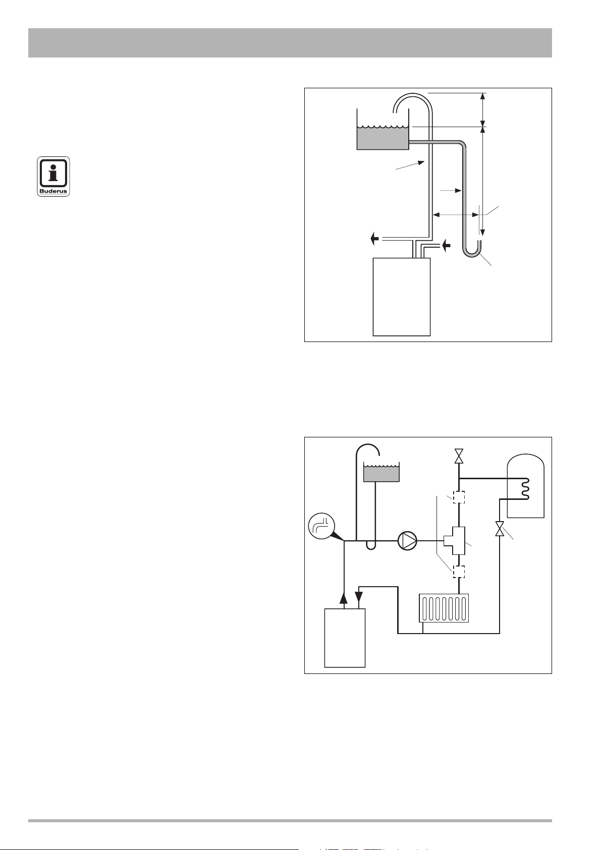
Open vent system requirements
The system should be vented directly off the boiler flow pipe, as
close to the boiler as possible. The cold feed entry should be
inverted and MUST be positioned between the pump and the vent,
and not more than 150 mm (6") away from the vent connection.
NOTE
Combined feed and vent pipes may also be
fitted.
Feed / expansion
cistern
Wate r
level
(cold)
22 mm
open vent
15 mm
cold
feed
450 (18")
minimum
1000 (40")
minimum
150 (6")
max.
There should be a minimum height, 450 mm (18"), of open vent
above the cistern water level. The vertical distance between the
highest point of the system and the feed/expansion cistern water
level MUST not be less than 1000 mm (40"). The pump must be
fitted on the flow side of the boiler.
A suitable pump is a domestic circulator capable of providing a
maximum 11 °C (20 °F) temperature differential across the boiler
with the whole of the heating circuit open. With the minimum flow
circuit allowed by the controls the differential must not exceed
25 °C (see also the graph on page 5).
The vertical distance between the pump and feed/expansion
cistern MUST comply with the pump manufacturer’s minimum
requirements, to avoid cavitation. Should these conditions not
apply either lower the pump position or raise the cistern above the
minimum requirements specified by Boulter Buderus. The
isolation valves should be fitted as close to the pump as possible.
Schematic pipework and system balancing
The boiler does not normally need a bypass but at least some
radiators on the heating circuit, of load at least 10% of the
minimum boiler output, must be provided with twin lockshield
valves so that this minimum heating load is always available (see
footnote re. thermostatic radiator valves).
Balancing
1. Set the programmer to ON for both CH and HW. Turn the
cylinder thermostat down. Close the manual or thermostatic
valves on all radiators leaving the twin lockshield valves (on
the radiators referred to above) in the open position. Turn up
the room thermostat and adjust these lockshield valves to give
boiler flow and return temperatures not more than 20 °C apart.
These valves should now be left as set.
2. Open all manual or thermostatic radiator valves and adjust the
lockshield valves on remaining radiators to give around 11 °C
temperature drop at each radiator.
3. Turn up the cylinder thermostat and adjust the cylinder
balancing valve so that the cylinder achieves a maximum flow
consistent with adequate flow to the radiators. Check that with
only the domestic hot water loop in circuit a differential
temperature of 20 °C across the boiler is not exceeded.
4. Adjust room and cylinder thermostats and programmer to
NORMAL settings.
System
flow to
pump
Connection
to boilers
fig. 1 Open vent system
22 mm
open vent
15 mm
cold
feed
Elbow
then
tee
Flow
Return
BOILER
fig. 2 Schematic pipework and system
System
return
Air vent
Alternative
2x2 port
valves
Radiators
Inverted cold
feed entry
3 port
valve
Cylinder
balancing
valve
Subject to modifications resulting from technical improvements! Boulter Buderus Ltd. • http://www.boulter-buderus.co.uk
6 Installation and maintenance instructions wall-mounted condensing gas boiler Buderus 600 - 11R/19R/24R • 05/2004
Page 7
Thermostatic radiator valves
k
Boulter Buderus support the recommendations made in
BS. 5449, and by leading manufacturers of domestic heating
controls, that heating systems utilising the thermostatic
radiator valve control of temperature in individual rooms shall
also be fitted with a room thermostat, controlling the
temperature in a space served by radiators not fitted with such
a valve.
Such an arrangement will provide for potentially more efficient
control of the environment and will also avoid the continuous
running of the circulation pump during programmed heating
ON periods - thus saving electrical energy.
It is, therefore, strongly recommended that, when thermostatic
radiator valves are used, space heating temperature control
over a living/dining area or a hallway having a heating
requirement of at least 10% of the minimum boiler heat output,
is achieved using a room thermostat whilst other rooms are
individually controlled by thermostatic radiator valves.
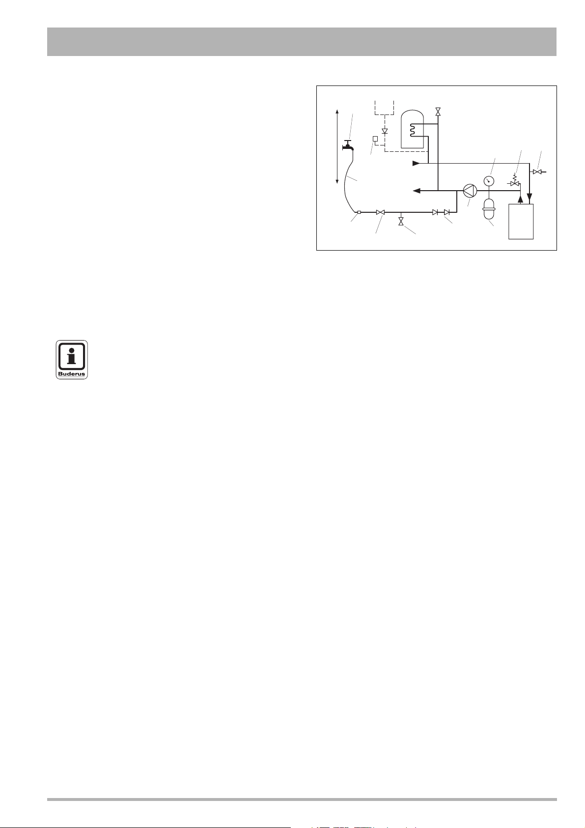
Sealed system requirements
NOTE
The method of filling, refilling, topping up or
flushing sealed hot water circuit from the mains
via a temporary hose connection is only
allowed if acceptable to the local water
authority.
1. General
The installation must comply with the requirements of
BS. 6798 and BS. 5449.
The installation should be designed to work with flow
temperatures of up to 80 °C.
All components of the system, including the heat exchanger of
the indirect cylinder, must be suitable for a working pressure of
3 bar (45 lb/in
2
) and temperature of 110 °C. Care should be
taken in making all connections so that the risk of leakage is
minimised.\
2. Safety valve
A spring loaded safety valve complying with the relevant
requirements of BS. 6759 must be fitted in the flow pipe as
close to the boiler as possible and with no intervening valve or
restriction. The valve should have the following features:
– A non-adjustable preset lift pressure not exceeding 3 bar
(45 lb/in
2
);
– A manual testing device;
– Provision for connection of a discharge pipe. The valve or
discharge pipe should be positioned so that the discharge
of water or steam cannot create a hazard to the occupants
of the premises or cause damage to electrical components
and wiring.
Make-up vessel
(max. capacity 3 litres)
Hose union
bib tap
Water
supply
Hose connector
Nonreturn
valve
Automatic
air vent
Hosepipe
(disconnect
after refilling)
BS. 1010:2
stop tap
HEATING
CIRCUIT
Test cock
Air vent
Pump
Double check valve
Pressure gauge
Expansion
vessel
Safety valve
BOILER
Drain coc
fig. 3 Sealed system
3. Pressure gauge
A pressure gauge covering at least the range of 0-4 bar
(0-60 lb/in
2
) must be fitted to the system. The gauge should be
easily seen from the filling point and should preferably be
connected at the same point as the expansion vessel.
4. Expansion vessel
A diaphragm type expansion vessel must be connected to a
point close to the inlet side of the pump, the connecting pipe
being not less than 15 mm (½" nominal) size and not
incorporating valves of any sort.
The vessel capacity must be adequate to accept the
expansion of the system water when heated to 110 °C
(230° F).
The charge pressure must not be less than the static water
head above the vessel. The pressure attained in the system
when heated to 110 °C (230° F) should be at least 0.35 bar
2
(5 lb/in
) less than the lift pressure of the safety valve.
For guidance on vessel sizing refer to table 1.
For further details refer to BS. 5449 and BS. 7074:1 and the
British Gas Corporation publication: "Material and Installation
Specifications for Domestic Central Heating and Hot Water".
5. Cylinder
The cylinder must be either of the indirect coil type or a direct
cylinder fitted with an immersion calorifier which is suitable for
operating on a gauge of 0.35 bar (5 lb/in
2
) in excess of the
safety valve setting. Single feed indirect cylinders are not
suitable for sealed systems.
6. Make-up water
provision must be made for replacing water loss from the
system, either:
– from a manually filled make-up vessel with a readily visible
water level. The vessel should be mounted at least 150 mm
(6") above the highest point of the system, and be
connected through a non-return valve to the system, filled
at least 300 mm (12") below the make-up vessel on the
return side of the domestic hot water cylinder or radiators.
or
– where access to a make-up vessel would be difficult by
pre-pressurisation of the system. Refer to "Filling", below.
Subject to modifications resulting from technical improvements! Boulter Buderus Ltd. • http://www.boulter-buderus.co.uk
Installation and maintenance instructions for wall-mounted condensing gas boiler Buderus 600 - 11R/19R/24R • 05/2004 7
Page 8
7. Mains Connection
There must be no direct connection to the mains water supply
or to the water storage tank supplying domestic water, even
through a non-return valve, without the approval of the local
water authority.
8. Filling
The system may be filled by one of the following methods:
a. Through a cistern, used for no other purpose, via a ball
valve permanently connected directly to a service pipe
and/or a cold water distributing pipe. The static head
available from the cistern should be adequate to provide
the desired initial system design pressure. The cold feed
pipe from the cistern should include a non-return valve and
a stop valve with an automatic air vent connected between
them, the stop valve being located between the system and
the automatic air vent. The stop valve may remain open
during normal operation of the system if automatic water
make-up is required.
b. Through a self-contained unit comprising a cistern,
pressure booster pump (if required) and, if necessary, an
automatic pressure reducing valve and flow restrictor. The
cistern should be supplied through a temporary connection
from a service pipe or cold water distributing pipe.
This unit may remain permanently connected to the
heating system to provide limited automatic water makeup. Where the temporary connection is supplied from a
service pipe or distributing pipe which also supplies other
draw-off points at a lower level then a double check valve
shall be installed upstream of the draw-off point.
c. Through a temporary hose connection from a draw-off tap
supplied from a servicing pipe under mains pressure.
Where the mains pressure is excessive a pressure
reducing valve shall be used to facilitate filling.
The following fittings shall form a permanent part of the system
and shall be fitted in the order stated:
– A stop valve complying with the requirements of
BS. 1010, Part 2 (the hose from the draw-off tap shall
be connected to this fitting);
– A test cock;
– A double check valve of an approved type.
z Thoroughly flush out the whole of the system with cold
water, without the pump in position.
z With the pump filled, fill and vent the system until the
pressure gauge registers 1.5 bar (21.5 lb/in
2
). Examine
for leaks.
z Check the operation of the safety valve by manually
raising the water pressure until the valve lifts. This
should occur within ± 0.3 bar (4.3 lb/in
2
) of the preset lift
pressure.
z Release water from the system until the initial system
design pressure is reached.
z Light the boiler and heat the system to the maximum
working temperature. Examine for leaks.
z Turn off the boiler and drain the system while still hot.
z Refill and vent the system.
z Adjust the initial pressure to the required valve.
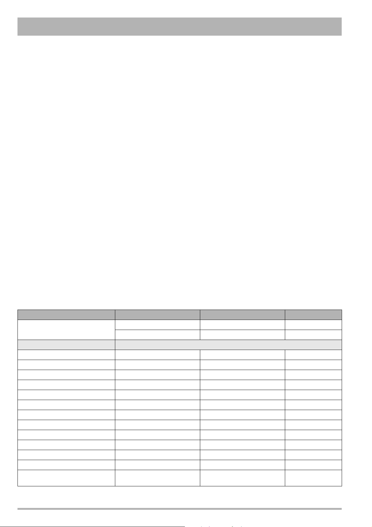
Sizing procedure for expansion vessel
The volume of the expansion vessel (litres) fitted to a sealed
system shall not be less than that given by the table below,
multiplied by a factor of 0.8 (for flow temperatures of less than
80 °C).
Safety valve setting 3.0 bar 2.5 bar 2.0 bar
Vessel charge and initial system
pressure
Total water content of system (litres) Expansion vessel volume litres
25 2.1 2.7 3.9 2.3 3.3 5.9 2.8 5.0
50 4.2 5.4 7.8 4.7 6.7 11.8 5.6 10.0
75 6.3 8.2 11.7 7.0 10.0 17.7 8.4 15.0
100 8.3 10.9 15.6 9.4 13.4 23.7 11.3 20.0
125 10.4 13.6 19.5 11.7 16.7 29.6 14.1 25.0
150 12.5 16.3 23.4 14.1 20.1 35.5 16.9 30.0
175 14.6 19.1 27.3 16.4 23.4 41.4 19.7 35.0
200 16.7 21.8 31.2 18.8 26.8 47.4 22.6 40.0
225 18.7 24.5 35.1 21.1 30.1 53.3 25.4 45.0
250 20.8 27.2 39.0 23.5 33.5 59.2 28.2 50.0
275 22.9 30.0 42.9 25.8 36.8 65.1 31.0 55.0
300 25.0 32.7 46.8 28.2 40.2 71.1 33.9 60.0
Multiplying factors for other
system volumes
Table 1 Expansion vessel volumes
0.5 1.0 1.5 0.5 1.0 1.5 0.5 1.0
bar bar bar bar bar bar bar bar
0.0833 0.109 0.156 0.094 0.134 0.237 0.113 0.20
Subject to modifications resulting from technical improvements! Boulter Buderus Ltd. • http://www.boulter-buderus.co.uk
8 Installation and maintenance instructions wall-mounted condensing gas boiler Buderus 600 - 11R/19R/24R • 05/2004
Page 9
Installation 1
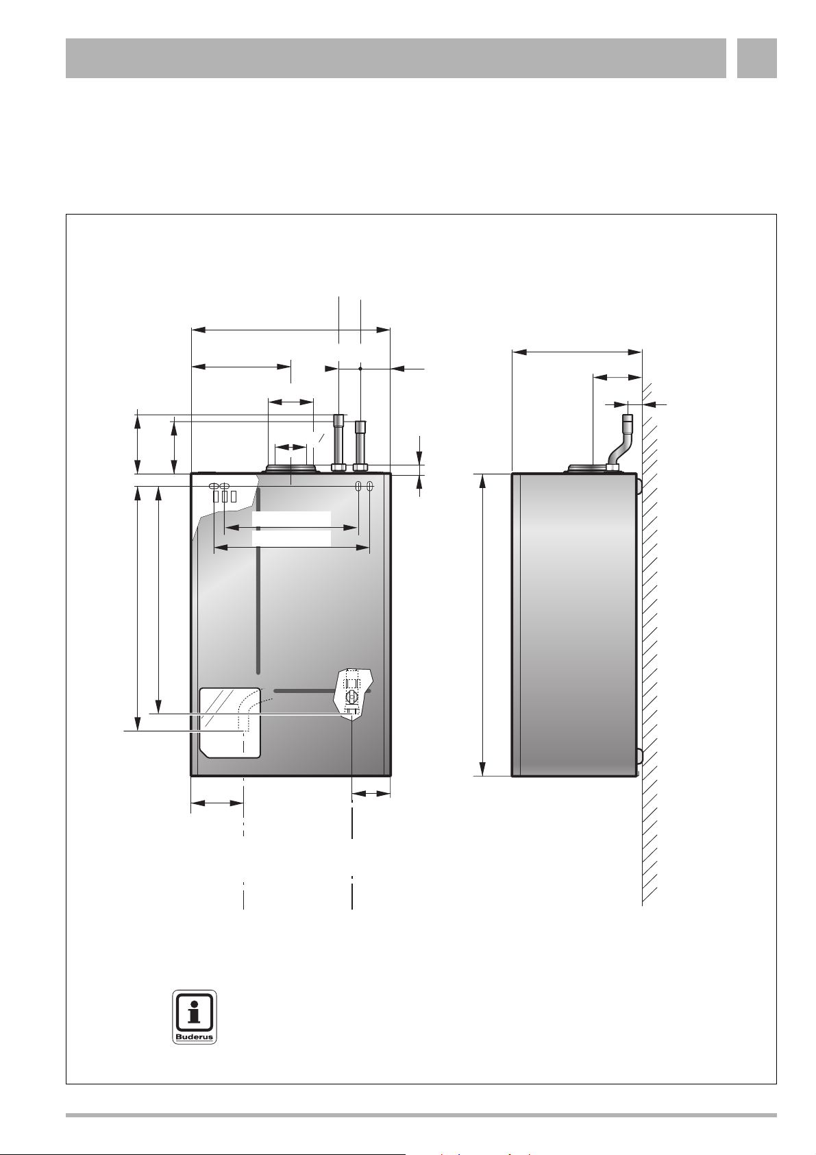
1 Installation
1.1 Dimensions and connections
CH FLOW
CH RETURN
460 mm (18")
290 mm (11,4")
105 mm (4")
230 mm (9")
50 (2")
70 (2.8")
130 (5")
145 (5,7")
619 mm (24")
604 mm (23,7")
Ø100 (4")
3
Ø60 (2 ")
328 mm (13")
376 mm (15")
25 mm (1")
8
20 (0.8")
700 mm (27½")
119 mm (4,7")
82 mm (3")
CWDO
GAS
CH Flow = Ø22 mm Compression (0.87")
CH return = Ø22 mm Compression (0.87")
GAS = Gas connection G½" INSIDE
CWDO = Condensate water drainage outlet Ø21.5 mm (0.8") OUTSIDE
NOTE
See the wall-mounting template for the necessary clearances.
Subject to modifications resulting from technical improvements! Boulter Buderus Ltd. • http://www.boulter-buderus.co.uk
Installation and maintenance instructions for wall-mounted condensing gas boiler Buderus 600 - 11R/19R/24R • 05/2004 9
Page 10
Installation1
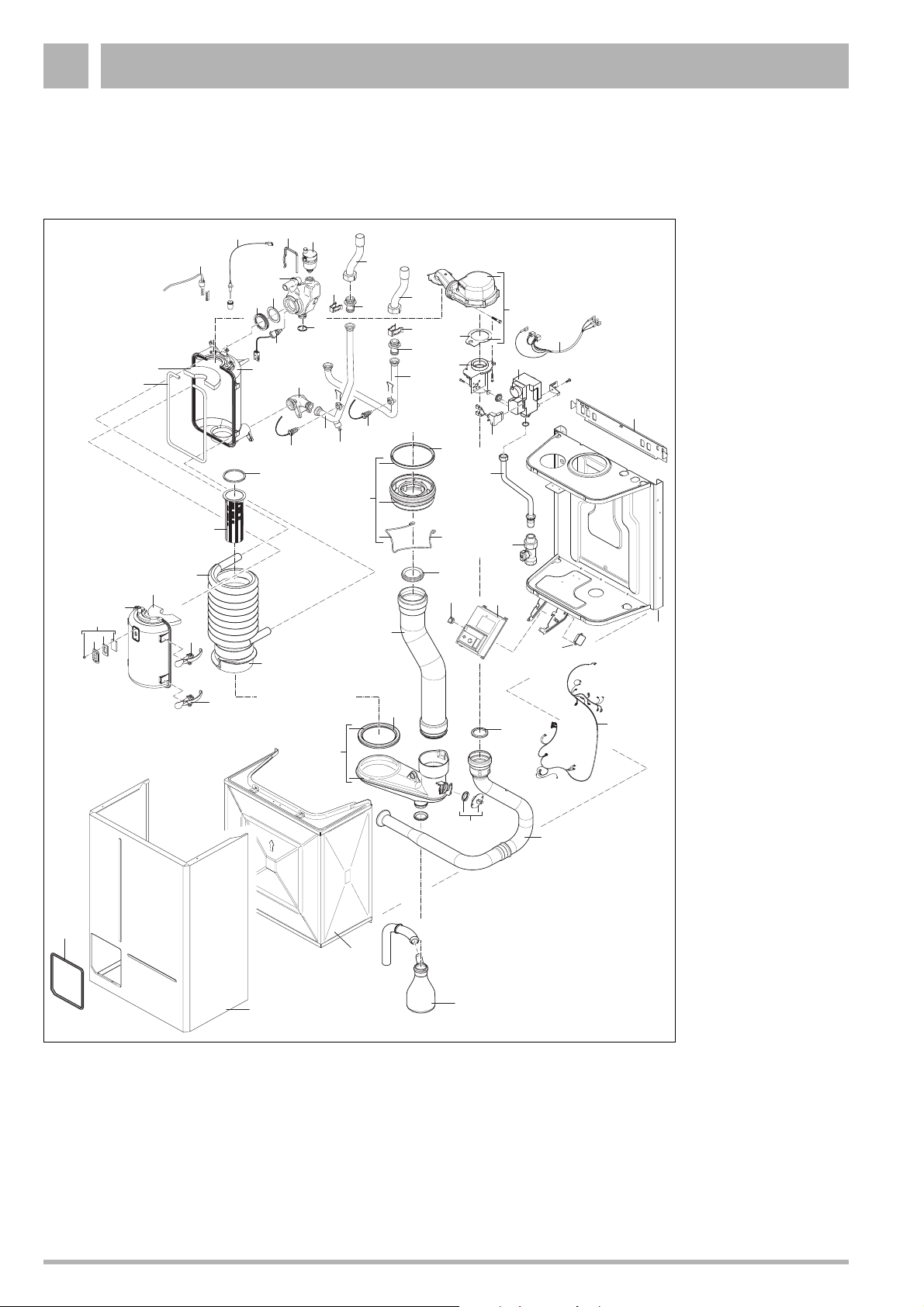
1.2 Boiler assembly - exploded view
Single unit (11R / 19R / 24R)
350
10
380
310
340
420
440
360
320
290
330
250
370
280
260
270
120
520
510
400
390
410
430
450
460
470
480
480
20
Legend
10. Casing
230
110
130
230
250
240
300
200
70
60
100
500
80
170
530
180
40
560
540
160
90
190
210
220
490
140
150
240
290
50
30
20. Door complete
30. Ventilation cover
40. Bracket
50. Concentric adaptor
60. Clip adaptor
70. Lipring 100mm
80. Fan
90. Sealing Fan / Venturi
100. Lipring 60mm
110. Flue gas pipe
120. Condensate collector
130. Seal flue gas pipe
140. Flue gas sensor
150. Condensate trap
160. Suction pipe
170. Lipring 50mm
180. Gas valve
190. Rectifier
200. Venturi
210. Gas pipe
220. Gas service valve
550
230. Pipe return/flow top
240. Pipe connection
250. Clip
260. Return pipe
270. Drain cock
280. Connection return
290. Sensor
300. Flow pipe
310. Connection supply
320. Hairpin heat exchanger
330. Automatic air vent
340. O-ring
350. Lipring
360. Safety sensor
370. Sealing ring
380. Backpart heat
exchanger
390. Seal heat exchanger
400. Insulation backpart heat
exchanger
410. Burner 11 kW
Burner 19 kW
Burner 24 kW
420. Sealing burner
430. Heat exchanger helix
440. Combustion divider
450. Insulation front heat exchanger
460. Frontpart heat exchanger
470. Sight glass
480. Fasteners
490. UBA
500. Main switch
510. Hot surface ignitor
520. Ionisation electrode
530. Cable fan
540. Cable harness
550. Frame
560. RTH converter 230V
Subject to modifications resulting from technical improvements! Boulter Buderus Ltd. • http://www.boulter-buderus.co.uk
10 Installation and maintenance instructions for wall-mounted condensing gas boiler Buderus 600 - 11R/19R/24R • 05/2004
Page 11
Installation 1
1.3 Flue Installation
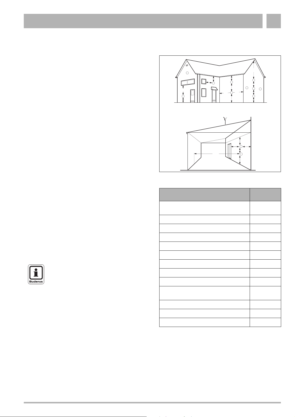
1.3.1 Siting the flue terminal
The flue must be installed in accordance with the
recommendations of BS. 5440-1:2000.
Pluming will occur at the terminal so terminal positions where
this could cause a nuisance should be avoided.
The air supply and the flue gas exhaust must meet the
applicable general regulations. Please consult the instructions
provided with the flue terminal kits prior to installation.
The boiler MUST be installed so that the terminal is exposed
to external air.
It is important that the position of the terminal allows the free
passage of air at all times.
Minimum acceptable spacing from the terminal to obstructions
and ventilation openings are specified in table 1.
If the terminal is fitted within 1000 mm of a plastic or painted
gutter or within 500 mm of painted eaves, an aluminium shield
of at least 1000 mm long should be fitted to the underside of
the gutter or painted surface.
If the lowest part of the terminal is less than 2 metres above the
level of the ground, balcony, flat roof or place to which any
person has access, the terminal must be protected by a guard.
Protective guards are available from Quinnell Barrett and
Quinnell, Old Kent Road, London.
Ensure that the guard is fitted centrally.
The flue assembly shall be so placed or shielded as to prevent
ignition or damage to any part of the building.
The air inlet/products outlet duct and the terminal of the boiler
MUST NOT be closer than 25 mm (1'') to combustible material.
Detailed recommendations on the protection of combustible
material are given in BS. 5440 - 1:2000.
NOTE
It is absolutely essential to ensure, in practice,
that products of combustion discharging from
the terminal cannot re-enter the building or any
other adjacent building through ventilators,
windows, doors, other sources of natural air
infiltration, or forced ventilation/airconditioning.
If this could occur the appliance MUST be turned off (with the
owners permission), and labelled as unsafe until corrective
action can be taken.
A
B,C
M
A
F
M
G
under carport
H, I
B,C
K
F
F
G
D
K
G
Fig. 1 Flue terminal position
Terminal Position
A. Directly below or alongside an opening
window, air vent or other ventilation opening
B. Below guttering, drain pipes or soil pipes
C. Below eaves
D. Below balconies or a car port roof
E. From vertical drain pipes or soil pipes
F. From internal or external corners
G. Above adjacent ground, roof or balcony level
H. From a surface facing the terminal
I. From a terminal facing a terminal
J. From an opening in a car port (e.g. door or
window) into dwelling
K. Vertically from a terminal on the same wall
L. Horizontally from a terminal on the wall
M. Adjacent to opening
C
K
L
L
K
G
FJ
Minimum
Spacing
300 mm (12")
75 mm (3")
200 mm (8")
200 mm (8")
150 mm (6")
300 mm (12")
300 mm (12")
600 mm (24")
1200 mm (48")
1200 mm (48")
1500 mm (60")
300 mm (12")
300 mm (12")
Table 1 Balanced flue terminal position
Subject to modifications resulting from technical improvements! Boulter Buderus Ltd. • http://www.boulter-buderus.co.uk
Installation and maintenance instructions for wall-mounted condensing gas boiler Buderus 600 - 11R/19R/24R • 05/2004 11
Page 12
Installation1
1.3.2 Air supply and flue gas exhaust in a closed installation
A ventilation cover is integrated into the 600 Series condensing
gas boilers. This cover houses a number of components, such
as the burner and the heat exchanger. Since this ventilation
cover is part of the air supply system, it is vital that it is always
installed correctly.
To ensure optimal operation, the 600 Series appliances must
be connected to a Buderus wall-mounted or roof-mounted flue
terminal. These terminals have been developed specifically for
the 600 Series condensing gas boilers and have been
comprehensively tested. The Buderus wall and roof-mounted
flue terminal kits ensure trouble-free operation.
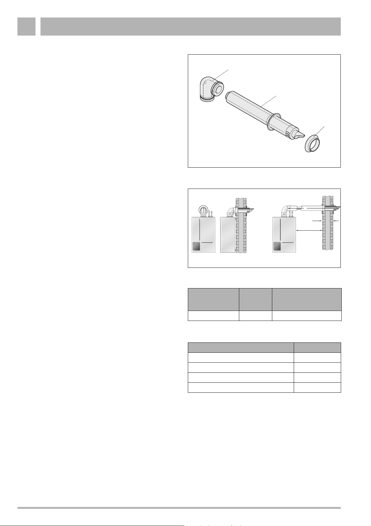
The following items for the flue (see fig. 2) are included in the
delivery of the boiler:
– pos. 1: 1 Concentric bend 60/100;
– pos. 2: 1 Horizontal flue terminal 60/100;
– pos. 3: 1 Flue finishing kit.
1.3.3 Maximum Flue length
The maximum pipe length of the air supply and flue gas
exhaust pipes for the 600 Series condensing gas boilers (see
table 2) is determined by the total pressure loss of all
components in the flue gas exhaust / air supply system.
1
Fig. 2 Horizontal flue pack
2
3
L
550 mm
50 mm
Take the flue conduit clearances into account when planning
the layout of the place of installation (see subsection 1.3.1:
"Siting the flue terminal" on page 11).
Maximum wall thickness without extensions is 550 mm.
Maintain a minimum side wall clearance of 50 mm (see fig. 3).
1.3.4 Additional flue parts
Additional flue parts (see table 3) can be ordered from your
supplier.
Fig. 3 Side flue and rear flue installation
Boiler
600 Series L = 7.5 m 1.2 m
Table 2 Pipe length
Flue parts Order No.
Concentric pipe, 500 mm long, adjustable NE 83703
Concentric pipe, 1000 mm long, not adjustable NE 83704
Concentric bend 90° NE 83705
Concentric bend 45° NE 83706
Table 3 Additional flue parts
Maximum
pipe length
For every 90° bend the
maximum pipe length has
to be reduced by
Subject to modifications resulting from technical improvements! Boulter Buderus Ltd. • http://www.boulter-buderus.co.uk
12 Installation and maintenance instructions for wall-mounted condensing gas boiler Buderus 600 - 11R/19R/24R • 05/2004
Page 13
Installation 1
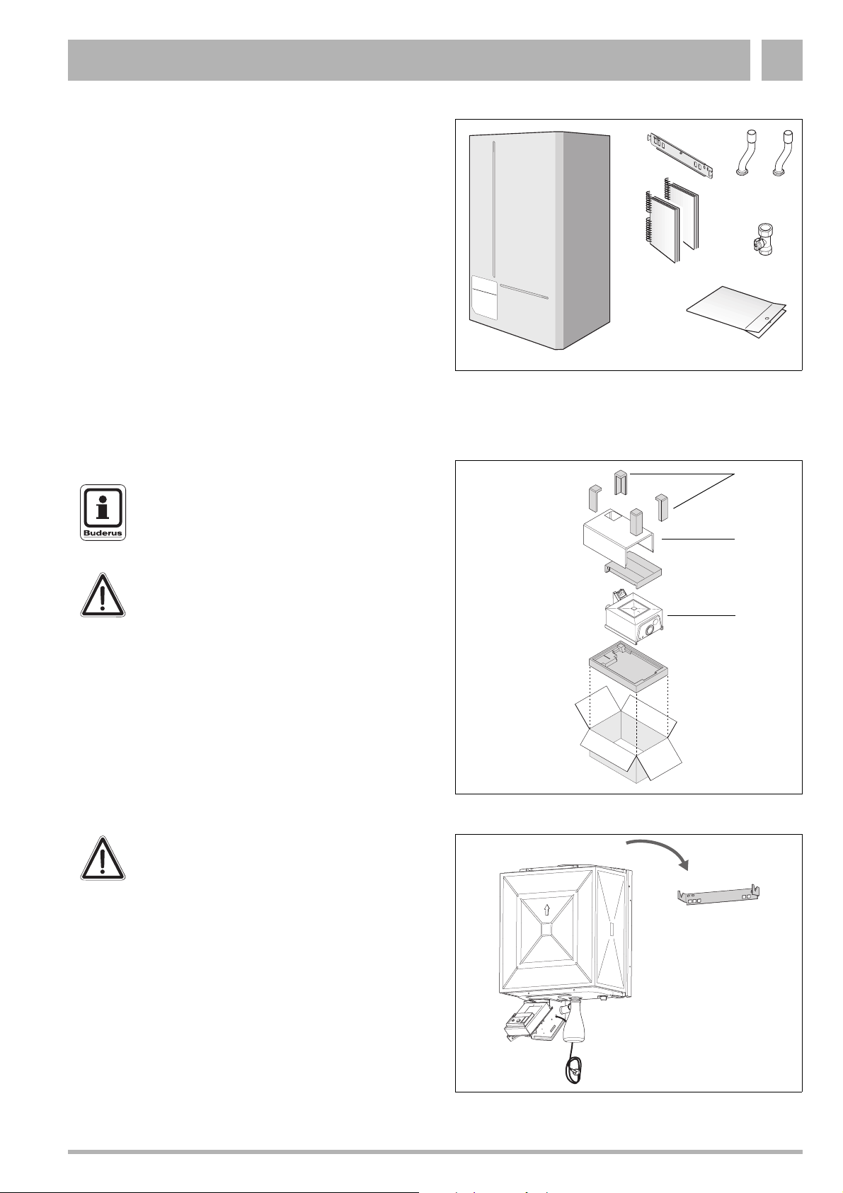
1.4 Items supplied with unit
z Check the contents against the packing list to ensure that
nothing is missing.
Key to fig. 4:
1: Wall-mounted condensing gas boiler
2: Wall bracket
3: Technical documents
4: CH Flow connection pipe
5: CH Return connection pipe
6: Gas service valve
7: Plastic bag containing the following accessories:
2 x wall fixing-screws
2 x wall plugs
2 x washers
Seals (2 x ¾“)
Square wrench
Initial start-up sticker
Second identification plate
Requirements to be met by the place of installation
NOTE
Observe all statutory building regulations
applying to the place of installation.
1
Fig. 4 Items supplied with unit
2
5
4
3
6
7
1
2
DANGER!
Inflammable materials or liquids must not be
stored or used near wall-mounted condensing
gas boilers. The site of installation must be
frost-protected.
1.5 Transport
The boiler is transported in a horizontal position.
z Open the box and remove the four foam supports (fig. 5,
item 1). The casing is not attached to the boiler.
z Take out the casing (fig. 5, item 2) and put aside during
installation.
CAUTION!
Do not carry the boiler by the casing at any
time.
z Take out the wall bracket (fig. 4, item 2) and attach to the
wall using the wall mounting template.
z Take out the condensing gas boiler (fig. 5, item 3) and
hang onto the wall bracket (fig. 6).
z Dispose of packaging.
3
Fig. 5 Unpacking the box
Fig. 6 Installation
Subject to modifications resulting from technical improvements! Boulter Buderus Ltd. • http://www.boulter-buderus.co.uk
Installation and maintenance instructions for wall-mounted condensing gas boiler Buderus 600 - 11R/19R/24R • 05/2004 13
Page 14
Installation1
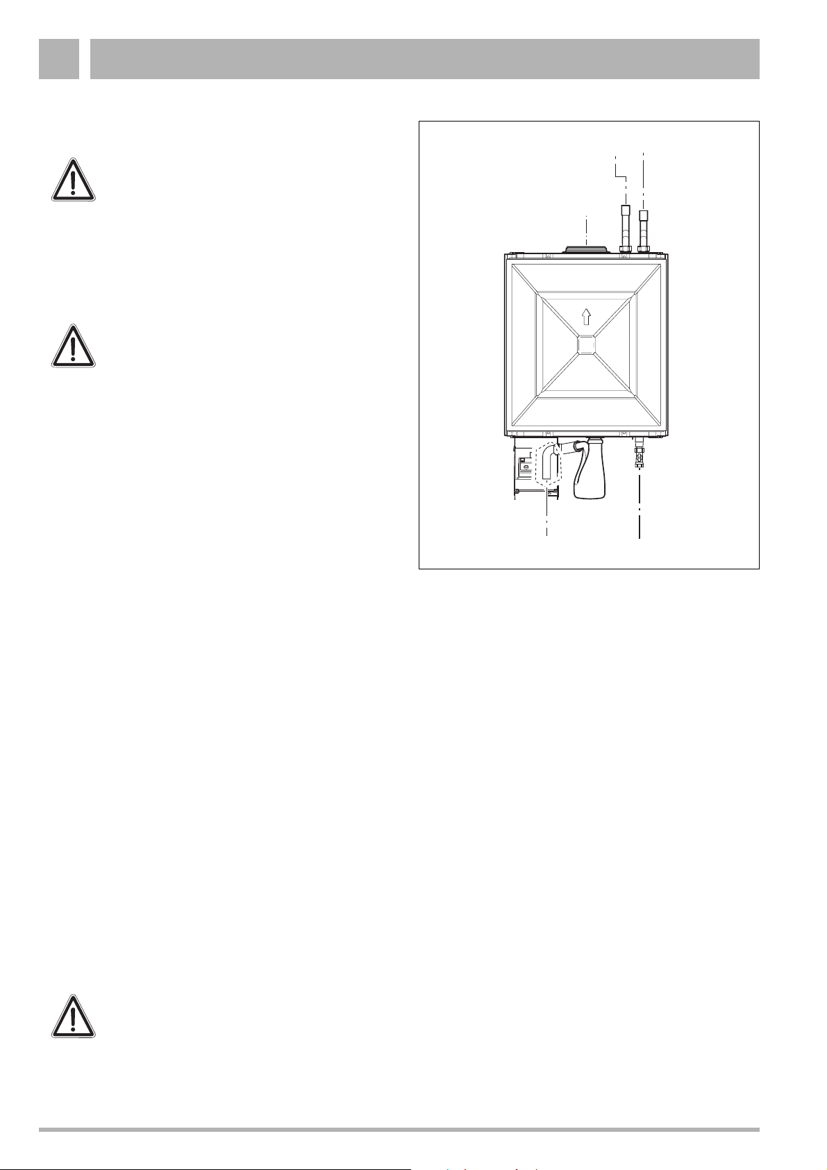
1.6 Pipe connections
CAUTION!
Ensure that all pipework is routed so as to
minimise any strain on the boiler fittings.
1.6.1 Gas Supply
The gas installation must be installed in accordance with
BS.6891.
CAUTION!
Pipework from the meter to the boiler MUST be
of adequate size.
The complete installation MUST be tested for gas tightness
and purged as described in IGE/UP/1b.
1.6.2 Gas connection
12
z A gas service valve is supplied with the unit. Take it out of
the box and connect it to the boiler see fig. 7, item 3 with
P.T.F.E.-tape. Connect to gas supply according to the
relevant standards.
1.6.3 Heating system connections
The central heating system should be in accordance with
BS.6798 and, in addition, for smallbore and microbore
systems, BS.5449.
z Take the CH flow connection pipe and the CH return
connection pipe out of the box and connect to the
condensing gas boiler see fig. 7, item 1 and 2.
z Connect the central heating system to these pipe
connections according to the relevant standards.
1.6.4 Condensate drain
A condensate drain is integrated in the boiler. The drain outlet
is a standard (21.5 mm) overflow pipe. This drain needs to be
connected to a drainage point. All pipework and fittings in the
condensate drainage system MUST be made of plastic - no
other materials may be used.
The routing of the drain must be made to allow a minimum fall
of 1 in 20 away from the boiler, throughtout its length.
4
Fig. 7 Pipe connections
Key to fig. 7:
1: CH flow
2: CH return
3: Gas
4: Condensate water drainage outlet (CWDO)
3
Excessive external pipe runs should be avoided in order to
prevent possible freezing.
Any external pipework should be a minimum of 32 mm internal
diameter.
WARNING!
Any external run must be insulated.
Ensure that the condensate trap is filled with water.
Subject to modifications resulting from technical improvements! Boulter Buderus Ltd. • http://www.boulter-buderus.co.uk
14 Installation and maintenance instructions for wall-mounted condensing gas boiler Buderus 600 - 11R/19R/24R • 05/2004
Page 15

Installation 1
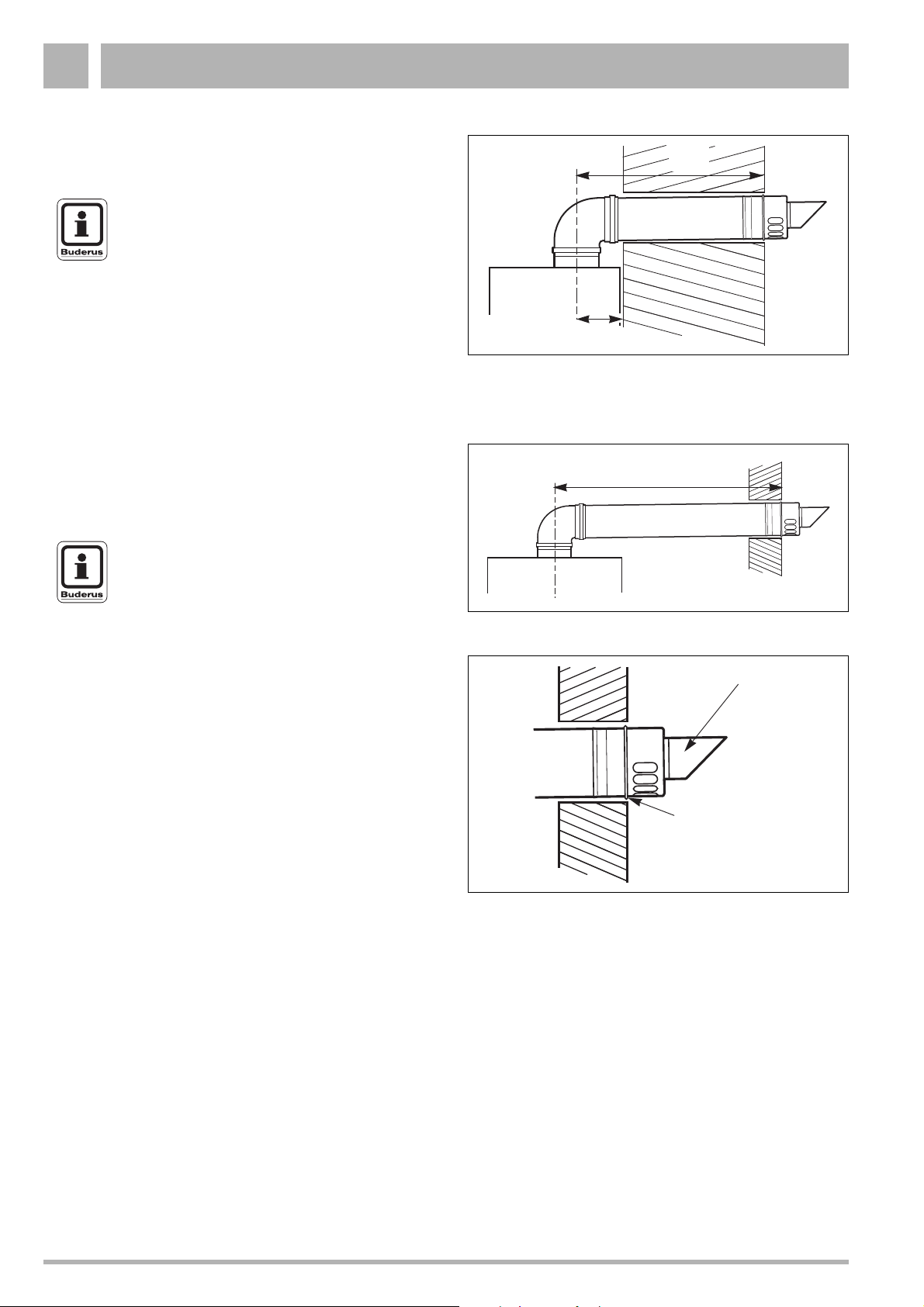
1.7 Flue installation
The only flue systems that may be used are those supplied by
Boulter Buderus. The flue system must be installed in
accordance with the requirements of BS.5440:1. 2000.
Standard 100 mm flue systems
The standard concentric flue system provides for a max.
horizontal straight length of upto 7.5 m (see subsection 1.3.3).
Full instructions for fitting this flue are in subsection 1.7.2:
"Installation of the horizontal flue" on page 15.
IMPORTANT
Any horizontal flue system fitted to a
condensing boiler must be inclined towards the
appliance at an angle of 3% (30 mm per metre
length) to prevent condensate dripping from
the flue terminal.
This means that the clearance above the
appliance must be increased to match the duct
length. See figure on page 9.
1.7.1 Connecting the vertical flue gas duct
z Fit the vertical flue gas duct (fig. 8) onto the appliance flue
connector.
z For remaining installation of the vertical flue assembly,
refer to the relevant installation instructions.
1.7.2 Installation of the horizontal flue
The standard 100 mm diameter horizontal flue system is
siutable for lengths upto 560 mm (see fig. 10).
For longer flue runs upto 7.5 m, extension air/flue ducts are
available (see page 12, table 3).
NOTE
Use the wall-mounting template to help you
mark the position of the side flue opening
Flue gas
testing point
Fig. 8 Vertical flue connection
Flue gas
testing point
Fig. 9 Elbow with flue gas testing point
Flue
Turret
Maximum 560 mm
No Clamp
Terminal
assembly
Outer
Wall
Fig. 10 Standard flue
Subject to modifications resulting from technical improvements! Boulter Buderus Ltd. • http://www.boulter-buderus.co.uk
Installation and maintenance instructions for wall-mounted condensing gas boiler Buderus 600 - 11R/19R/24R • 05/2004 15
Page 16
Installation1
1.7.3 Flue duct preparation and assembly
z Measure the flue length L. Refer to figures 11 and 12.
NOTE
The flue must be inclined to the boiler.
z Mark of the lengths shown onto the ducts and cut the
length. The cuts must be square and free from burrs.
Terminal assembly outer (air) duct - L-70 mm, inner (flue)
duct - L-50 mm. The measurement is made from the ridge
at the terminal indicating the outer face of the wall.
Refer to figure 13.
Extension air duct - L-70 mm, flue duct - L-50 mm.
The measurement is from the formed end.
z Assemble flue system completely. Push the ducts fully
together. The slope of the terminal outlet must be face
downwards.
The assembly will be made easier if a solvent free grease
is lightly applied to the male end of the ducts.
NOTE
An inner wall sealing plate is provided which
should be fitted to the ducts before assembly.
L
105
Fig. 11 Flue length - rear
L
z Push the assembly through the wall and slide the turret
onto the flue connector. Refer to figure 9.
z Ensure that the turret is fully entered into the socket on the
boiler. From the outside fix the flue finishing kit to the
terminal and, after ensuring the duct is properly inclined
towards the boiler, fix the finishing kit to the wall.
If the terminal is within 2 m of the ground where there is
access then an approved terminal guard must be fitted.
The guard must give a clearance of at least 50 mm around
the terminal and be fixed with corrosion resistant screws.
Fig. 12 Flue length - side
Outer
Wall
Face
Fig. 13 Flue terminal position
Flue Terminal
Raised Ring
locating the
terminal relative
to the outside
wall face
Subject to modifications resulting from technical improvements! Boulter Buderus Ltd. • http://www.boulter-buderus.co.uk
16 Installation and maintenance instructions for wall-mounted condensing gas boiler Buderus 600 - 11R/19R/24R • 05/2004
Page 17
Installation 1
1.8 Electrical connections
1.8.1 Mains connection
CAUTION
This appliance MUST be earthed.
A mains supply of 230 V - 50Hz is required.
External controls are suitable for volt free or 230 V installation.
Wiring to the boiler MUST be in accordance with the current
I.E.E. (BS.7671) Wiring Regulations and any local regulations.
Wiring should be a 3 core PVC insulated cable, not less than
0.75 mm
Connection must be made in a way that allows complete
isolation of the electrical supply such as a double pole switch
having 3 mm (1/8'') contact seperation in both poles, or a plug
and socket, serving only the boiler and system controls. This
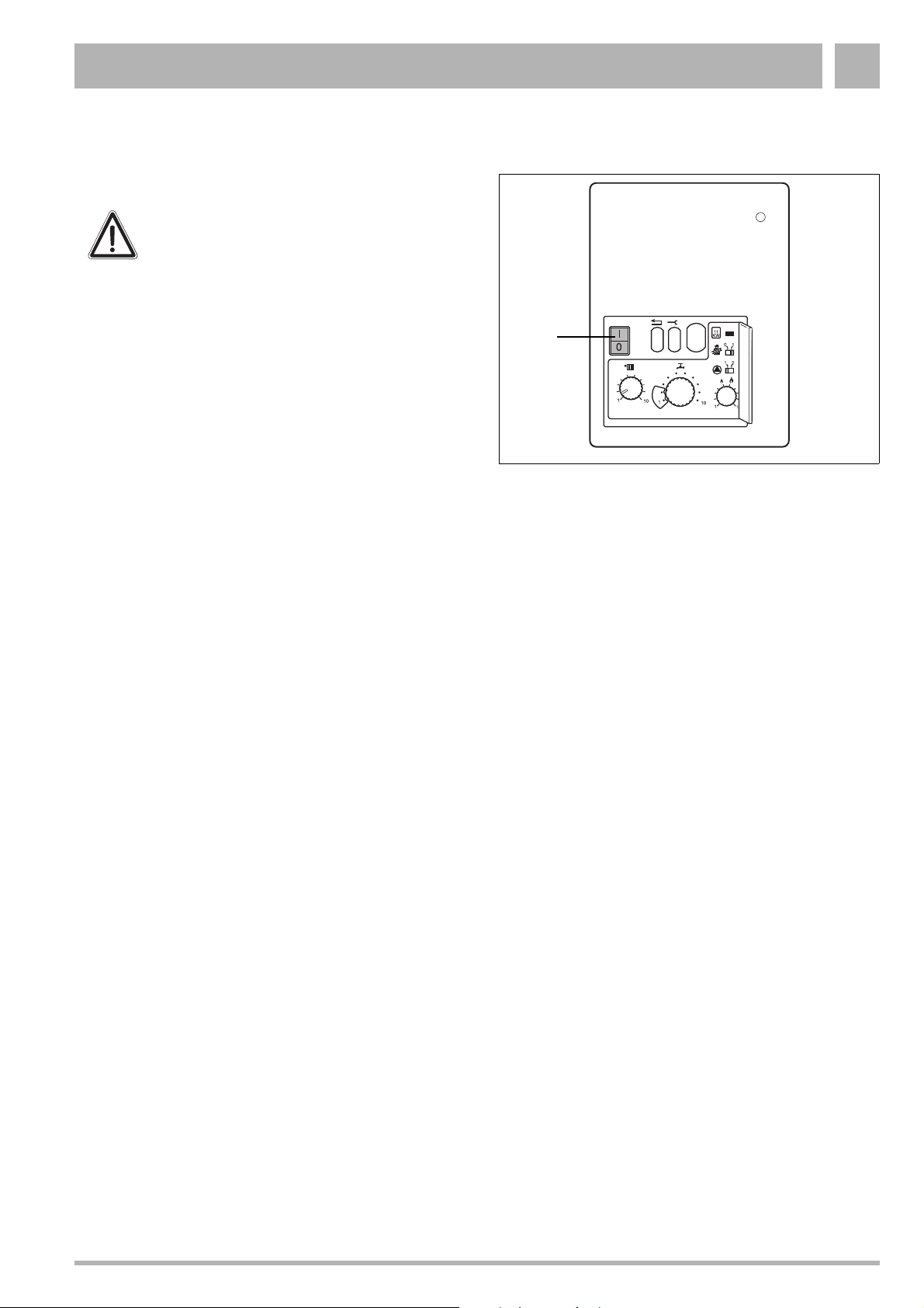
boiler is equipped with a double pole switch see fig. 14, item 1.
The means of isolation must be accessible to the user after
installation.
The electrical connection to the mains supply should be readily
accessible and adjacent to the boiler.
If the supply cord is damaged, it must be replaced by a
registered Corgi installer to avoid a hazard.
2
(24 x 0.2 mm), and to BS.6500 Table 16.
1
Fig. 14 UBA
Subject to modifications resulting from technical improvements! Boulter Buderus Ltd. • http://www.boulter-buderus.co.uk
Installation and maintenance instructions for wall-mounted condensing gas boiler Buderus 600 - 11R/19R/24R • 05/2004 17
Page 18
Installation1
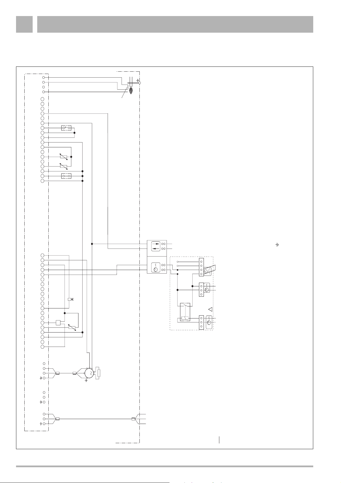
1.8.2 Wiring Diagram
4
12 3
18-pin connection strip
FS
FR
PA
Burner-control unit (UBA)
Flame-monitoring electrode
ignitor
Hot surface
STB
Fuse, main switch, emergency OFF switches and
safety measures to comply with local regulations and standards
port
I/O
Communication
24Vac
12 34
MV
1234
To Boiler
1234
RTH
321
Loop
1)
ON/OFF-
potential free
room thermostat
!
20-pin connection strip
KIM
FK
1 2 3 4 5 6 7 8 9 10 11 12 13 14 15 16 17 18 19 20 1 2 3 4 5 6 7 8 9 10 11 12 13 14 15 16 17 18
3
2
1
12 1 2
N
M
L
Ventilator
50 Hz
~
230V
Mains power source
Max. permitted
10A
fuse rating
STB Flue gas monitor
230Vac
321
230 Vac ON/OFF-
room thermostat
device may be connected.
FR Return-temperature sensor (return)
FS Safety-temperature sensor (safety)
FK Supply-temperature sensor (supply)
KIM Boiler identification module
MV Solinoid valve
Note:
1) Only one room-temperature regulating
IMPORTANT
The wires inthis mains lead are coloured in accordance with the following code:
GREEN AND YELLOW - EARTH ; BLUE - NEUTRAL ; BROWN - LIVE
As the colours of the wires in the mains lead of of the appliance may not correspond with the coloured markings identifying the terminals in your plug proceed as follows:
The wire coloured green and yellow must be connected to the terminal on the plug marked with the letter E or by the earth symbol or coloured green or green-and-yellow. The wire coloured brown must be connected to the terminal marked with
the letter L or coloured red. The wire coloured blue must be connected to the terminal marked with the letter N or coloured black.
FOR LOCATION OF INDIVIDUAL COMPONENTS, SEE TROUBLESHOOTING GUIDE IN THE SERVICE SECTION OF THIS MANUAL.".
WARNING
THIS APPLIANCE MUST BE EARTHED
Ensure that your appliance is connected correctly - if you are in any doubt consult a qualified electrician.
Subject to modifications resulting from technical improvements! Boulter Buderus Ltd. • http://www.boulter-buderus.co.uk
18 Installation and maintenance instructions for wall-mounted condensing gas boiler Buderus 600 - 11R/19R/24R • 05/2004
Page 19

Installation 1
1.9 Timing and temperature control
The wall-mounted condensing gas boiler can be fitted with the
following control devices:
– ON/OFF temperature controller, volt free;
– A room-temperature control device at 230V connected to
the RTH converter see fig. 15, item 2.
1.9.1 230V Room-temperature control device connection
CAUTION
DO NOT activate the condensing gas boiler at
this stage.
z Lead the 230V control device wire through the cable lead
(see fig. 15, item 1).
z Fix the 230V wire to position 1 and 2 of the 230V
connection (see fig. 15, item 2).
z Secure the 230V wire with the bracket and the two screws
onto the RTH converter.
1.9.2 Volt free room-temperature control device connection
z Remove the cover of the connextion box (fig. 16, item 1).
z Lead the control device wire through the cable lead
(see fig. 16, item 2).
z Fix the wire to position 1 and 2 of the volt free connection
(see fig. 16, item 3).
z Secure the wire with the bracket and the two screws onto
the RTH converter (see fig. 16, item 4).
Fig. 15 Connecting the control device
2
1
1
2
3
Fig. 16 RTH converter - Volt free connection
Subject to modifications resulting from technical improvements! Boulter Buderus Ltd. • http://www.boulter-buderus.co.uk
Installation and maintenance instructions for wall-mounted condensing gas boiler Buderus 600 - 11R/19R/24R • 05/2004 19
Page 20

Initial start-up2
12
10
01
11
KW
10
1
1
2 Initial start-up
2.1 Preparing the boiler for operation
CAUTION
DO NOT operate the condensing gas boiler if
large amounts of dust are present, e.g. due to
building work in and around the place of
installation.
2.1.1 Checking for leaks
z Disconnect the system from the power supply.
z Check all sections of gas pipework and connections for
signs of leaks before starting up system for the first time.
If a leak is detected during tightness testing, use an
approved leak detector to check all connections for
possible escapes. The product must be certified as a gas
leak-testing agent. DO NOT allow the product to come into
contact with electrical wiring.
Fig. 17 Unscrew ventilation cover
2.1.2 Purging air from the gas supply system
z Loosen the 4 crosshead screws on the ventilation cover
(fig. 17).
z Remove the ventilation cover.
z Close the gas service valve.
z Unscrew the sealing closure of the gas connection-
pressure testing nipple by two turns (fig. 18).
z Purge system and appliance as per relevent procedures,
IGE/UP/1b. Ensuring all safety requirments are met.
z Open gas service valve.
z Close the gas service valve once more.
z Shut the sealing closure of the test nipple once more.
z Open cover for 2nd operating level (fig. 19, item 1).
z Make sure that system pump is running.
z Start boiler up and move chimney sweep switch (fig. 19,
item 3) to position “1”.
The display shows (fig. 19, item 2) “
-.” or “ =.” to indicate that
the gas supply system is purged of air. Return chimney sweep
switch to position “0”.
Fig. 18 Purging air from the gas supply system
2
3
1
Subject to modifications resulting from technical improvements! Boulter Buderus Ltd. • http://www.boulter-buderus.co.uk
20 Installation and maintenance instructions for wall-mounted condensing gas boiler Buderus 600 - 11R/19R/24R • 05/2004
Fig. 19 Display and chimney-sweep switch
Page 21
Initial start-up 2
2.1.3 Check combustion air/flue gas connection
Check to ensure that the correct combustion air/flue gas
system has been fitted.
Check that the instructions included in the appropriate flue gas
system installation manual have been followed.
2.1.4 Checking the type of gas and supply
CAUTION
The burner must only be put into operation with
the correct nozzles (table 5).
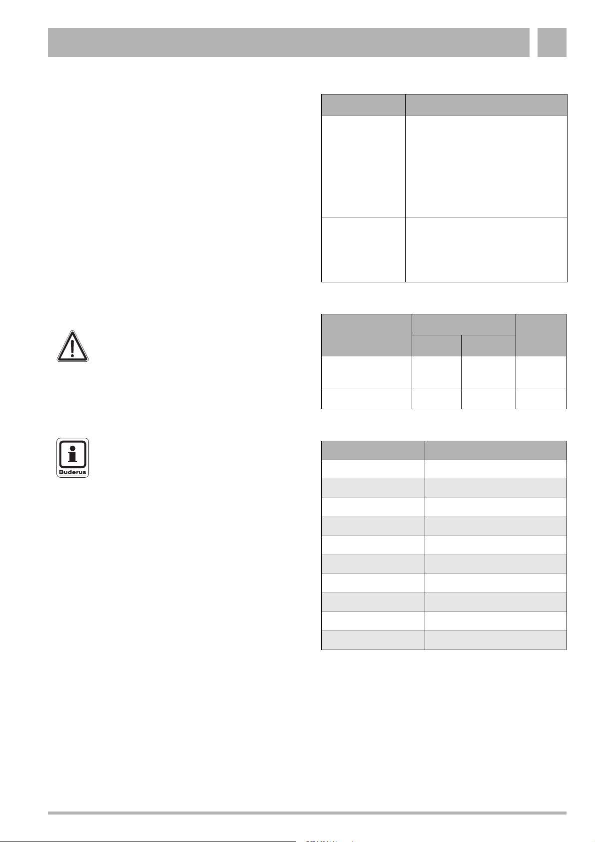
Type of gas Factory settings of gas burners
When delivered ready for operation
and set to Wobbe index 14.1 kWh/m
(referred to 15 °C, 1,013 mbar),
Natural gas H
applicable for Wobbe index range
11.3 to 15.2 kWh/m
3
.
Inscription on gas-type indicating
label:
Category setting: G 20 - 2E_20 mbar
After adaptation by a CORGI
registered installer, the unit can be
Propane P
run on propane.
Inscription on gas-type indicating
label: 3P G 31_30-50 mbar
Table 4 Gas-supply types
Type of gas
supply
Natural gas H
(G20)
Gas nozzles ∅ [mm]
11R 19R/24R
Venturi
tubes
5.55 6.5 Standard
3
NOTE
Observe stickers attached to Venturi tubes.
Propane P 3.40 4.15 Standard
Table 5 Gas-nozzle diameter
Controller setting Flow temperature [°C]
1 40
2 44
3 48
4 53
5 58
6 62
7 67
8 71
9 76
10 80
Table 6 Flow temperature
Subject to modifications resulting from technical improvements! Boulter Buderus Ltd. • http://www.boulter-buderus.co.uk
Installation and maintenance instructions for wall-mounted condensing gas boiler Buderus 600 - 11R/19R/24R • 05/2004 21
Page 22

Initial start-up2
12
10
01
11
KW
10
1
1
2.1.5 Adjusting the flow temperature
z Open the cover to the 2nd operating level (fig. 20, item 1).
z Adjust the knob (fig. 20, item 2) to the desired flow
temperature (table 6) for your particular installation.
NOTE
Factory setting of the controller is "10"
(around 83 °C).
NOTE
If the flow temperature is set too low, there is
the risc that an external hot water cylinder
cannot achieve a comfortable enough
temperature.
2
1
Fig. 20 Control box
Key to Fig. 20:
1: Cover for second operating level
2: Flow temperature knob
3: Heat-capacity jumper
4: Heating capacity knob
5: only used when boiler is in service mode
6: only used when boiler is in service mode
3
56
4
2.1.6 Setting the heating capacity
Set the heating capacity (table 7), according to the amount of
heat required, at the controller (fig. 20, item 4).
NOTE
The controller is factory-adjusted to position “6”
Controller
setting
Heating capacity [kW] (±5 %)
11 R 19 R 24 R
14.99.79.7
2 5.6 10.7 11.3
3 6.3 11.8 12.9
4 6.9 12.8 14.5
5 7.6 13.8 16.0
6 8.3 14.9 17.6
7 9.0 15.9 19.2
8 9.6 16.9 20.8
9 10.3 18.0 22.4
10 11.0 19.0 24.0
Table 7 Heating capacity
Subject to modifications resulting from technical improvements! Boulter Buderus Ltd. • http://www.boulter-buderus.co.uk
22 Installation and maintenance instructions for wall-mounted condensing gas boiler Buderus 600 - 11R/19R/24R • 05/2004
Page 23

Initial start-up 2
12
10
01
11
KW
10
1
1
2.1.7 Measure gas-supply pressure (flow pressure)
z Open at least one radiator thermostat valve.
CAUTION
The condensing gas boiler must not be
activated at this stage.
z Make sure that the system pump is running.
z Turn the chimney-sweep switch (fig. 21, item 4) to
position “1”.
z Loosen the screw plug on the gas test nipple (fig. 22) by
two turns.
z Attach the pressure-gauge connection hose to the gas test
nipple (fig. 23).
z Slowly open the gas service valve.
z Turn the power switch (fig. 21, item 2) to position “I”.
The burner should ignite after about 30 seconds.
z Measure the gas connection pressure and note it down on
the report form.
The gas-connection pressure must be
for natural gas H min. 17 mbar, max. 25 mbar, nominal
connection pressure 20 mbar.
for propane P min. 30 mbar, max. 50 mbar, nominal
connection pressure 37 mbar.
z Detach the gauge-connection tube once more and close
the test nipple at the screw plug.
.
NOTE
If the required connection pressure is not
available or too high, contact your gas supplier
or TRANSCO.
Ensure all disturbed joints and connections are checked for
gas tightness on completion of tasks.
3
4
2
1
Fig. 21 Mains switch, service button and chimney-sweep
switch
Fig. 22 Measure the gas connection pressure
2.1.8 Check the gas/air ratio and adjust as required
z Turn mains power switch (fig. 21, item 2) and chimney-
sweep switch (fig. 21, item 4) to “0”.
z Unscrew the sealing closure of the burner-pressure testing
nipple by one turn (fig. 22).
z Connect the positive port of the pressure gauge with a
hose to the burner pressure measuring nipple (fig. 23).
z Make sure that the system pump is running.
z Turn mains power switch to “I” and chimney-sweep switch
to “1”.
z If the burner has fired after approx. 30 seconds, keep the
service button (fig. 21, item 3) pressed until “Y” appears on
the display.
z Turn the hot-water temperature controller (fig. 21, item 1)
Fig. 23 Check the gas/air ratio
to “1”.
z Read the differential pressure.
The differential pressure (p
(±5 Pa = 0,05 bar) (display on measuring gauge: -10 Pa to
GAS–pAIR
) should total -5 Pa
0Pa).
Subject to modifications resulting from technical improvements! Boulter Buderus Ltd. • http://www.boulter-buderus.co.uk
Installation and maintenance instructions for wall-mounted condensing gas boiler Buderus 600 - 11R/19R/24R • 05/2004 23
Page 24

Initial start-up2
z If the gas/air ratio does not conform to specifications,
readjust at the setscrew (fig. 23, item 1).
z Turn mains power switch and chimney-sweep switch to “0”.
z Remove the measuring equipment and retighten the screw
in the burner-pressure measuring nipple.
z Readjust the hot-water temperature controller to its original
setting.
z Turn the mains power switch to “I”.
2.1.9 Record readings
z Unscrew the corresponding sealing closure (fig. 24) on the
connection adapter for the combustion-air/flue-gas system
and replace it once the measuring operation in question
has been carried out.
Carbon monoxide content
CAUTION
The carbon monoxide values under vacuum
must be smaller than 400 ppm or 0.04 Vol%.
Values around or exceeding 400 ppm indicate
a faulty burner adjustment, a dirty gas burner
or heat exchanger, or a defective burner.
Ensure that the cause of the fault is remedied
immediately.
2.1.10 Function testing
NOTE
During initial start-up and annual servicing,
make sure that all control, regulating and
safety devices are in full working order and, if
applicable, check for correct adjustment.
Measuring the ionisation current (fig. 25)
z Disconnect the system from the power supply.
z Loosen the plug-and-socket connector of the ionisation
electrode and connect the multimeter in series.
On the measuring device, select the µ-direct current range.
The measuring device must have a resolution of at
least 1 µA.
z Make sure that the system pump is running.
z Reconnect the system to the power supply and turn the
chimney-sweep switch to “1”.
z Measuring the ionisation current. The ionisation current
being checked must measure >2 µA direct current.
z Enter the reading on the report form.
z Disconnect the system from the power supply.
z Remove multimeter and restore the plug-and-socket
connection to its original state.
z Turn the chimney sweep switch to position “0”.
z Reconnect the system to the power supply.
When the display shows “7” and the service button is
pressed, the display turns to “c”. Press the Reset button.
The display shows “r”.
Fig. 24 Measuring points on exhaust conduit
Key to Fig. 24:
1: Exhaust-fume temperature, CO
2: Combustion-air temperature
, CO, NO
2
x
Fig. 25 Measuring the ionisation current
12
Subject to modifications resulting from technical improvements! Boulter Buderus Ltd. • http://www.boulter-buderus.co.uk
24 Installation and maintenance instructions for wall-mounted condensing gas boiler Buderus 600 - 11R/19R/24R • 05/2004
Page 25

Initial start-up 2
z Place the casing (see fig. 26, item 1).
z Tighten the fixing screw (see fig. 26, item 2).
2.1.11 Handing over
After completing the installation and commissioning of the
system the installer should hand over to the householder by
the following actions:
z Hand the User Manual to the householder and explain
his/her responsibilities under the relevant national
regulations.
z Explain and demonstrate the lighting and shutting down
procedures.
z The operation of the boiler and the use and adjustment of
all system controls should be fully explained to the
householder, to ensure the greatest possible fuel economy
consistent with the household requirements of heating.
Advise the user of the precautions necessary to prevent
damage to the system and to the building in the event of the
system remaining inoperative during frosty conditions.
z Explain the function and the use of the boiler heating
controls.
z Explain the function of the boiler fault mode. Emphasise
that if a fault is indicated, the boiler should be turned off and
a registered local heating installer consulted.
z Explain and demonstrate the function of time and
temperature controls, radiator valves etc., for the economic
use of the system.
Fig. 26 Place casing
1
2
Loss of system water pressure
z Explain that when there is a significant loss of pressure the
user should contact a Corgi registered installer.
WARNING
Do not fire the boiler if the pressure has
reduced to zero from the original setting.
z After installation, commissioning and customer handover
instructions please complete the BENCHMARK appliance
log book and leave this with the customer.
z IMPORTANT
A comprehensive service should be carried out annually.
Stress the importance of regular servicing by a Corgi
registered installer.
Subject to modifications resulting from technical improvements! Boulter Buderus Ltd. • http://www.boulter-buderus.co.uk
Installation and maintenance instructions for wall-mounted condensing gas boiler Buderus 600 - 11R/19R/24R • 05/2004 25
Page 26
Inspection3
3 Inspection
3.1 Preparing the heating boiler for inspection
z Disconnect the system.
DANGER OF FATAL INJURY
due to electric shock when system is
opened.
z Before opening the system:
disconnect the heating unit at the
emergency OFF switch or the
corresponding circuit breaker of the house
power supply.
z Ensure that the heating system cannot be
reconnected by accident.
z Remove the burner housing or cover from the heating
boiler.
NOTE
If the gas supply pipes are to be disconnected
from the burner, the housing MUST ONLY be
removed by a qualified service technician and
checked for tightness on reassembly.
For further information, please refer to subsection 8.2
"Inspection and maintenance reports" on page 54 and fill out
the Benchmark.
Subject to modifications resulting from technical improvements! Boulter Buderus Ltd. • http://www.boulter-buderus.co.uk
26 Installation and maintenance instructions for wall-mounted condensing gas boiler Buderus 600 - 11R/19R/24R • 05/2004
Page 27
Maintenance 4
4 Maintenance
For further information, please refer to subsection 8.2
"Inspection and maintenance reports" on page 54 and fill out
the Benchmark.
4.1 Clean the heat exchanger, burner and condensate trap
NOTE
The cleaning of the burner and heat exchanger
described here should be carried out whenever
there are signs of heavy soiling on the wallmounted condensing gas boiler. It is sufficient,
during annual servicing, to clean the burner
and heat exchanger with the help of an
appropriate cleaning product and a soft brush
and compressed-air hose (see following
section).
The heat exchanger can be dismantled
completely for thorough cleaning if required
(see “Cleaning the heat exchanger after
dismantling” on page 28).
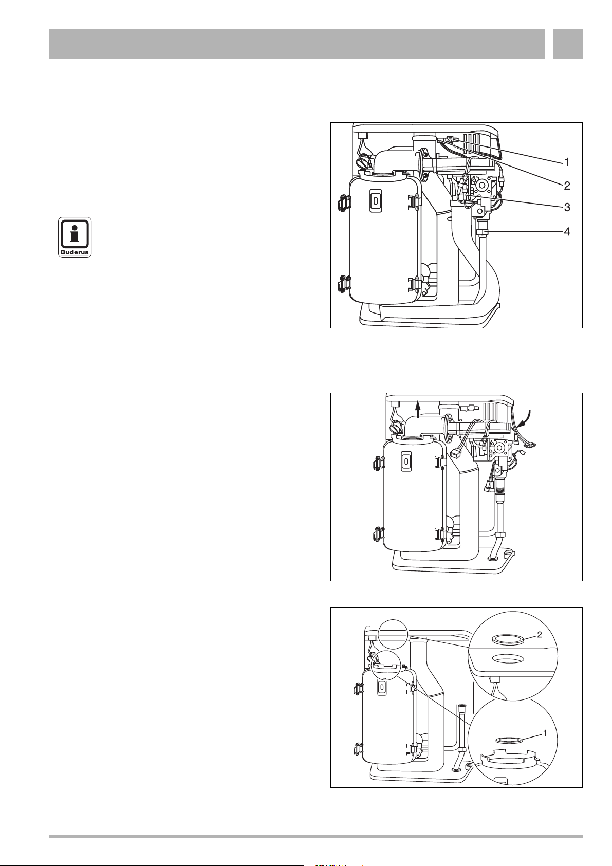
Fig. 27 Loosen the union nut and remove the cable
4.1.1 Cleaning the heat exchanger without dismantling
z Disconnect the system from the power supply.
z Close the gas service valve.
z Loosen the fixing screws, remove casing and ventilation
cover.
z Release plug-in connection of fan power lead (fig. 27,
item 1), burner-control unit fan control lead (fig. 27, item 2)
and gas-burner assembly (fig. 27, item 3).
z Loosen union nut on gas valve assembly (fig. 27, item 4).
z Push safety plate out of way.
z Turn air suction tube and pull off from below.
z Swivel the air combination unit forward (fig. 28, item 1).
z Pull the air combination unit up and out of bayonet
connector (fig. 28, item 2) and remove via front of unit.
z Remove burner gasket (fig. 29, item 1).
z Remove rubber seal in heat exchanger by pushing
upwards from inside (fig. 29, item 2).
2
Fig. 28 Remove the air combination unit
1
Fig. 29 Remove burner gasket and rubber seal
Subject to modifications resulting from technical improvements! Boulter Buderus Ltd. • http://www.boulter-buderus.co.uk
Installation and maintenance instructions for wall-mounted condensing gas boiler Buderus 600 - 11R/19R/24R • 05/2004 27
Page 28

Maintenance4
z Remove heat exchanger by pulling upwards through the
opening (fig. 30).
NOTE
Maintain the specified clearance of approx.
25 cm between the ceiling and the ventilation
cover.
z Remove the front of the heat exchanger. This is done by
releasing the four snap catches at the sides.
z Remove the hot surface ignitor (fig. 31, item 1) and
ionisation electrode (fig. 31, item 2).
In the case of the hot surface ignitor: loosen the fixing
screw of the hot surface ignitor, detach both earth (ground)
leads and remove the retaining plate of the hot surface
ignitor by pulling it upwards, withdraw the hot surface
ignitor by pulling it upwards.
In the case of the ionisation electrode: Swivel the
retaining plate to one side and carefully remove the
ionisation electrode by pulling it upwards.
z Clean the burner and both parts of the heat exchanger with
compressed-air or brush.
z Refit the heat exchanger by following the above procedure
in reverse order.
CAUTION
The gasket between the two halves of the
casing shell should normally be replaced.
Fit the new gasket by pressing in from the top
on both sides, and without stretching.
DO NOT attempt to cut the gasket to size.
Fig. 30 Remove burner
1
2
CAUTION
The burner gasket must match the shape of
the groove in the housing.
CAUTION
Check the heat-exchanger for leaks BEFORE
reassembling the casing shells.
4.1.2 Cleaning the heat exchanger after dismantling
z Disconnect the system from the power supply.
z Close the gas service valve.
z Loosen the retaining screw and remove the casing.
z Close the heating shutoff valves and drain the system.
CAUTION
Cut hot water on supply side by closing the
heating shutoff valve.
Fig. 31 Remove the hot surface ignitor and ionisation
electrode
Subject to modifications resulting from technical improvements! Boulter Buderus Ltd. • http://www.boulter-buderus.co.uk
28 Installation and maintenance instructions for wall-mounted condensing gas boiler Buderus 600 - 11R/19R/24R • 05/2004
Page 29
Maintenance 4
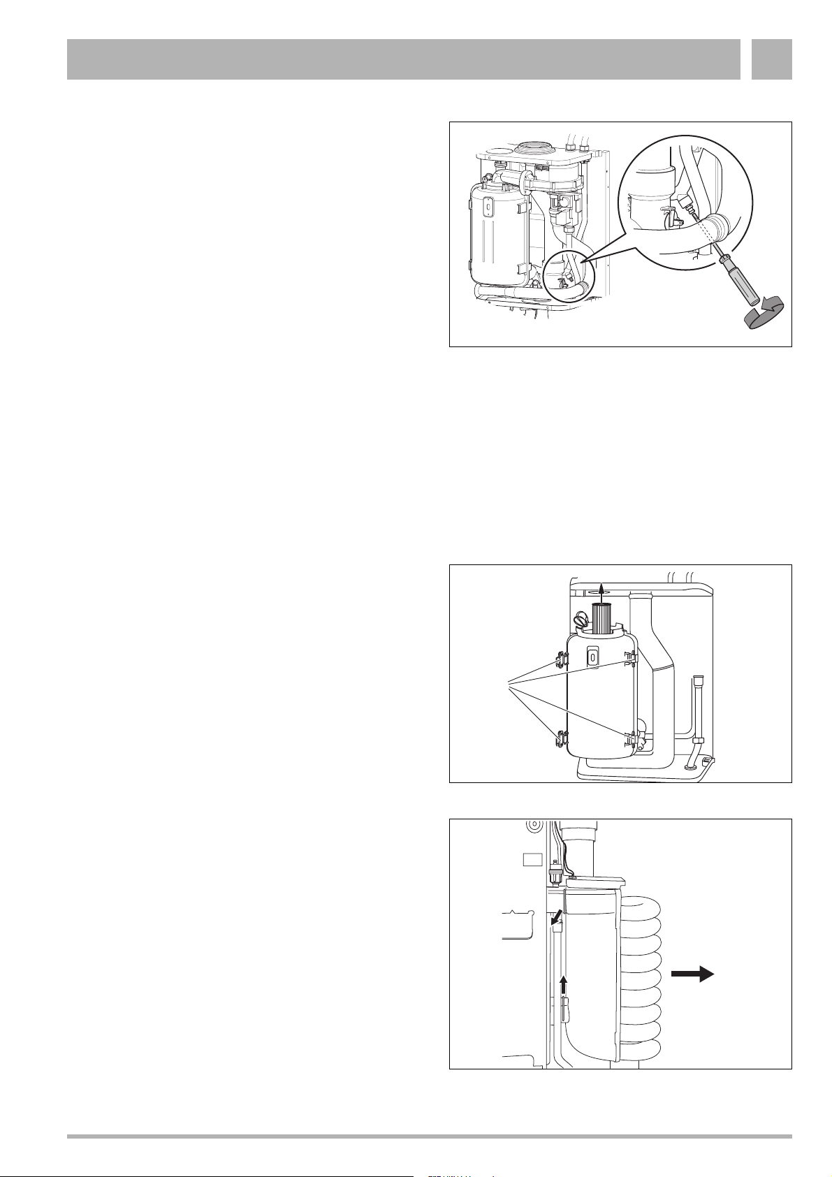
To drain the boiler take the following steps:
z First drain the system.
z In case of frost, drain the boiler.
z Loosen the draining nipple with a screwdriver see fig. 32.
z Attach temporary hose to the nipple. Connect the other
side of the temporary hose to a draining pipe.
z When the boiler is drained then tighten the draining nipple
screw.
z Release plug-in connection of fan power lead (fig. 27,
item 1, page 27), burner-control unit fan control lead
(fig. 27, item 2, page 27) and gas-burner assembly (fig. 27,
item 3, page 27).
z Loosen union nut on gas valve assembly (fig. 27, item 4,
page 27).
z Push safety plate out of way.
z Turn air suction tube and pull off from below.
z Swivel the air combination unit forward (fig. 28, item 1,
page 27).
z Pull the air combination unit up and out of bayonet
connector (fig. 28, item 2, page 27) and remove via front of
unit.
z Remove rubber seal in combustion chamber from top
(fig. 29, item 2, page 27).
Fig. 32 Draining the boiler
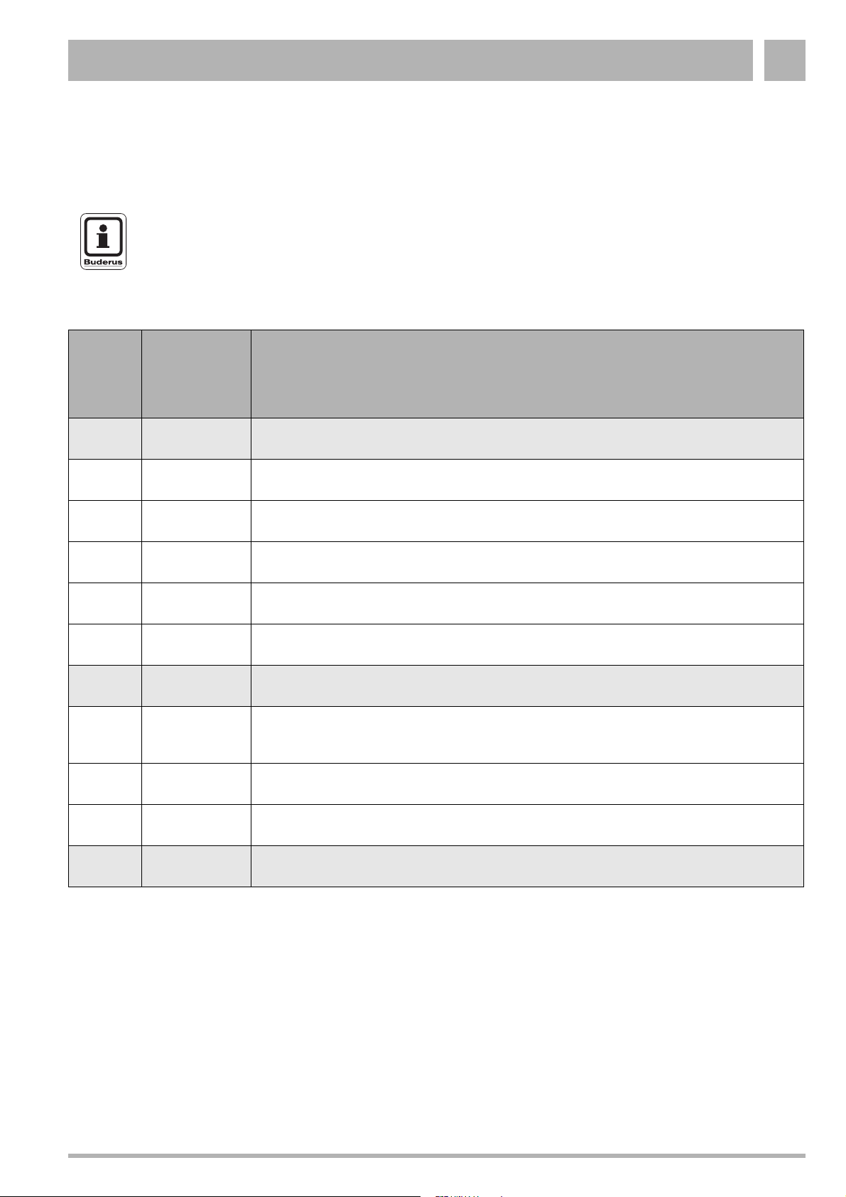
z Remove burner and burner gasket (fig. 29, item 1,
page 27) by pulling upwards through the opening (fig. 33,
item 1).
z Remove the front of the heat exchanger by releasing the
four retaining clips (fig. 33, item 2).
z Remove the hot surface ignitor (fig. 31, item 1) and
ionisation electrode (fig. 31, item 2).
In the case of the hot surface ignitor:
Loosen the fixing screw of the hot surface ignitor, detach
both earth (ground) leads and remove the retaining plate of
the hot surface ignitor by pulling it upwards, withdraw the
hot surface ignitor by pulling it upwards.
In the case of the ionisation electrode:
Swivel the retaining plate to one side and carefully remove
the ionisation electrode by pulling it upwards.
z Remove securing pin on flow and return connection
conduit (fig. 34) of heat exchanger.
z Remove spiral heat exchanger by pulling towards front
(fig. 34). Drain any water remaining in the heat exchanger
into the condensate trap.
1
2
Fig. 33 Remove burner and release retaining clips
Fig. 34 Securing pin on spiral heat exchanger
Subject to modifications resulting from technical improvements! Boulter Buderus Ltd. • http://www.boulter-buderus.co.uk
Installation and maintenance instructions for wall-mounted condensing gas boiler Buderus 600 - 11R/19R/24R • 05/2004 29
Page 30

Maintenance4
z Remove the diffusion head (fig. 35, item 2) on the
underside of the heat exchanger by withdrawing the
securing pin (fig. 35, item 1) and unscrewing the diffusion
head.
z Clean the front and back cover of the heat exchanger and
the heat exchanger with water or compressed air.
z Clean the burner with compressed air only.
Take care not to damage the fins of the heat exchanger.
Refitting (fig. 36) :
NOTE
Excessive flue gas temperatures may be an
indication of an incorrectly-fitted diffusion
head.
12
z Screw the diffusion head in as far as it will go on the
underside of the heat exchanger (the final turn of the heat
exchanger increases the clearance between the pipes) and
insert securing pin.
CAUTION
Take care not to damage the insulation on the
diffusion head.
z Check to ensure that the heat exchanger has been fitted
the right way round. The upper securing-pin groove must
be horizontal (fig. 36, item 1).
z Refit the heat exchanger by following the above procedure
in reverse. Note the following:
z The gasket between the front and back cover of the heat
exchanger should normally be replaced. Fit the new gasket
by pressing in from the top on both sides, and without
stretching. DO NOT attempt to cut the gasket to size.
z Check the heat exchanger for leaks BEFORE
reassembling the front and back cover of the heat
exchanger.
z Check O-ring seals (spiral), and replace as required.
z Smear the O-ring seal with a thin layer of silicone grease.
Fig. 35 Removing the diffusion head
1
Fig. 36 Refitting the heat exchanger
4.1.3 Cleaning the condensate trap
z Remove the trap and withdraw it from the outlet see fig. 37.
z Clean the condensate trap.
z Fill the condensate trap with water and then reassemble in
reverse order.
z Measuring the gas input pressure (flow pressure).
z Check the gas/air ratio.
z Leak test in operational condition.
z Measuring the carbon monoxide content.
z Carry out function testing.
Subject to modifications resulting from technical improvements! Boulter Buderus Ltd. • http://www.boulter-buderus.co.uk
30 Installation and maintenance instructions for wall-mounted condensing gas boiler Buderus 600 - 11R/19R/24R • 05/2004
Fig. 37 Removing the condensate trap
Page 31
Servicing 5
5 Servicing
5.1 Operating codes
NOTE
If the code displayed on the burner-control unit
is not listed under the operating codes or fault
warnings, the burner-control unit itself is
malfunctioning.
Display Display after
pressing the
service
button
0 Buderus 600 - 11R / 19R / 24R is ready for operation
A Burner interval circuit, 10 min. from burner start-up
H Standby activated, Buderus 600 - 11R / 19R / 24R ready to provide heat
L Initial safety period: self-testing of burner-control unit during burner start-up
U Post- or pre-purging period of fan unit
Y Flow temperature over setpoint
-. Buderus 600 - 11R / 19R / 24R running in heating mode
A
Meaning
“Chimney-sweep” mode, flow-temperature controller bypassed, Buderus 600 - 11R / 19R / 24R
heating to previously-entered flow temperature.
H Normal heating mode
Y Service mode
r Reset
Subject to modifications resulting from technical improvements! Boulter Buderus Ltd. • http://www.boulter-buderus.co.uk
Installation and maintenance instructions for wall-mounted condensing gas boiler Buderus 600 - 11R/19R/24R • 05/2004 31
Page 32

Servicing5
5.2 Fault codes
Code Meaning
2C Safety sensor exceeds 95 °C
Possible
cause
1 Resistance in the installation is too high Check if not all (thermostatic) radiator valves are clogged
2 Heating capacity is too large for the installation Adjust the heating capacity (see subsection 2.1.6)
3 Safety sensor is faulty Measure if resistance over the sensor is correct.
4 Problem with the pump or pump cabling (no circulation) Check if the pump cabling is faulty or if the pump is stuck
5 Water pressure is too low in the installation Top up the system
Code Meaning
2F Temperature difference between the safety sensor and flow sensor is greater than or equal to 15 °K
Possible
cause
1 Resistance in the installation is too high Check if not all (thermostatic) radiator valves are closed or
2 Safety sensor is dirty or faulty Check the safety sensor for dirt. Measure if resistance over
3 Flow sensor is dirty or faulty Check the sensor, replace if necessary (see subsection
4 Problem with the pump or pump cabling (no circulation) Check if the pump cabling is faulty or if the pump is stuck.
5 Water pressure is too low in the installation Top up the system
Action
with dirt.
If not replace safety sensor (see subsection 5.3.8,
subsection 5.3.9, subsection 5.3.10)
Action
clogged with dirt
the sensor is correct. If not replace safety sensor (see
subsection 5.3.8, subsection 5.3.9, subsection 5.3.10)
5.3.11, subsection 5.3.12, subsection 5.3.13)
Replace pump if necessary.
Code Meaning
2P Safety sensor rises faster than 5 °C/sec.
Possible
cause
1 Heating capacity is too large for the installation Adjust the heating capacity (see subsection 2.1.6)
2 Resistance in the installation is too high Check if not all (thermostatic) radiator valves are closed or
3 Safety sensor is dirty or faulty Check the safety sensor for dirt. Measure if resistance over
Subject to modifications resulting from technical improvements! Boulter Buderus Ltd. • http://www.boulter-buderus.co.uk
Action
clogged with dirt
the sensor is correct. If not replace safety sensor (see
subsection 5.3.8, subsection 5.3.9, subsection 5.3.10)
32 Installation and maintenance instructions for wall-mounted condensing gas boiler Buderus 600 - 11R/19R/24R • 05/2004
Page 33

Servicing 5
Code Meaning
2U Temperature difference between flow and return more than 55 °C
Possible
cause
1 Flow sensor is dirty or faulty Check the sensor, replace if necessary (see subsection
2 Problem with the pump or pump cabling (no circulation) Check if the pump cabling is faulty or if the pump is stuck.
3 Water pressure is too low in the installation Top up the system
4 Resistance in the installation is too high Check if not all (thermostatic) radiator valves are closed or
5 Safety sensor is dirty or faulty Check the safety sensor for dirt. Measure if resistance over
Code Meaning
3C Bad plug-in connection at cable harness, or damaged wiring
Possible
cause
1 Cable harness is faulty Check cable harness for faults and bad connections
2 Connectors at the back of the UBA are loose or faulty Check the connectors at the back of the UBA
3 UBA might be faulty Check the UBA by temporarily connecting an other UBA
Action
5.3.11, subsection 5.3.12, subsection 5.3.13)
Replace pump if necessary.
clogged with dirt
the sensor is correct. If not replace safety sensor (see
subsection 5.3.8, subsection 5.3.9, subsection 5.3.10)
Action
(see subsection 5.3.3)
Code Meaning
4A Flow sensor exceeds 100 °C
Possible
cause
1 Flow sensor is dirty or faulty Check the sensor, replace if necessary (see subsection
2 There is a problem with the pump or pump cabling
(no circulation)
3 Water pressure is too low in the installation Top up the system
Code Meaning
4C F2 fuse malfunction, or flue gas thermostat active
Possible
cause
1 Water pressure is too low in the installation Top up the system
2 Heat exchanger is dirty Check for a dirty heat exchanger and clean if necessary.
3 Flue gas retarder faulty or missing Check if the flue gas retarder is installed in the heat
4 Heat exchanger has a problem Purge heat exchanger
Action
5.3.11, subsection 5.3.12, subsection 5.3.13)
Check if the pump cabling is faulty or if the pump is stuck.
Replace pump if necessary.
Action
(see subsection 4.1)
exchanger
Subject to modifications resulting from technical improvements! Boulter Buderus Ltd. • http://www.boulter-buderus.co.uk
Installation and maintenance instructions for wall-mounted condensing gas boiler Buderus 600 - 11R/19R/24R • 05/2004 33
Page 34

Servicing5
Code Meaning
4F Safety sensor exceeds 95 °C
Possible
cause
1 Resistance in the installation is too high Check if not all (thermostatic) radiator valves are clogged
2 Heating capacity is too large for the installation Adjust the heating capacity
3 Safety sensor is faulty Check the sensor and measure if resistance over the
4 Problem with the pump or pump cabling (no circulation) Check if the pump cabling is faulty or if the pump is stuck
5 Water pressure is too low in the installation Top up the system
Code Meaning
4L Short circuit in safety sensor
Possible
cause
1 Safety sensor is faulty Check the sensor and measure if resistance over the
2 A short or bad connection in the cable harness Check the cable harness and/or connector of the sensor
3 UBA might be faulty Check the UBA by temporarily connecting a different UBA
Action
with dirt
sensor is correct. If not replace safety sensor (see
subsection 5.3.8, subsection 5.3.9, subsection 5.3.10)
Action
sensor is correct. If not replace safety sensor (see
subsection 5.3.8, subsection 5.3.9, subsection 5.3.10)
(see subsection 5.3.3)
Code Meaning
4P Safety sensor has a loose connection or is defective
Possible
cause
1 Safety sensor faulty or disconnected Check the sensor and measure if resistance over the
2 A short or bad connection in the cable harness Check the cable harness and/or connector of the sensor
3 UBA might be faulty Check the UBA by temporarily connecting a different UBA
Code Meaning
4U Short circuit in flow sensor
Possible
cause
1 Flow sensor is dirty or faulty Check the sensor, replace if necessary (see subsection
2 A short or bad connection in the cable harness Check the cable harness and/or connector of the sensor
3 UBA might be faulty Check the UBA by temporarily connecting a different UBA
Action
sensor is correct. If not replace safety sensor (see
subsection 5.3.8, subsection 5.3.9, subsection 5.3.10)
(see subsection 5.3.3)
Action
5.3.11, subsection 5.3.12, subsection 5.3.13)
(see subsection 5.3.3)
Subject to modifications resulting from technical improvements! Boulter Buderus Ltd. • http://www.boulter-buderus.co.uk
34 Installation and maintenance instructions for wall-mounted condensing gas boiler Buderus 600 - 11R/19R/24R • 05/2004
Page 35

Servicing 5
Code Meaning
4Y Flow sensor interrupted
Possible
cause
1 Flow sensor faulty or disconnected Check the sensor and measure if resistance over the
2 A short or bad connection in the cable harness Check the cable harness and/or connector of the sensor
3 UBA might be faulty Check the UBA by temporarily connecting a different UBA
Code Meaning
6A F1 fuse defective, or no ionisation message after ignition
Possible
cause
1 There is no flame, ionisation electrode doesn’t
glow, fan is turning
2 There is no flame, ionisation electrode does
glow, fan isn’t turning
3 There is no flame, ionisation electrode and fan
are working
4 There is a flame, but the flame disappears
when the fan starts up
Action
sensor is correct. If not replace safety sensor (see
subsection 5.3.11, subsection 5.3.12, subsection 5.3.13)
(see subsection 5.3.3)
Action
– Check wiring of the hot surface ignitor, measure the resistance
of the hot surface ignitor (should be between 50 and 300 Ohm).
Replace hot surface ignitor if necessary (see subsection 5.3.14
and subsection 5.3.15)
– Check the UBA’s F1 fuse, replace if necessary
– Check the fan and KIM connectors and the UBA fuses
– Check and adjust the gas/air ratio (see subsection 2.1.8)
– Check for 24 V~ on the gas valve during start up
– Check the gas-supply pressure (see subsection 2.1.7), this
should be higher than 20 mbar for natural gas.
– Check the earthing cable connections
(yellow/green wire).
– Check the cabling on the ionisation electrode
– Check the gas-supply pressure (see subsection 2.1.7), this
should be higher than 20 mbar for natural gas.
– Check and adjust the gas/air ratio (see subsection 2.1.8)
– Check the earthing cable connections (yellow/green wire)
– Check the cabling on the ionisation electrode
– Press reset. If fault code remains than try to temporarily connect
a different UBA (see subsection 5.3.3)
Subject to modifications resulting from technical improvements! Boulter Buderus Ltd. • http://www.boulter-buderus.co.uk
Installation and maintenance instructions for wall-mounted condensing gas boiler Buderus 600 - 11R/19R/24R • 05/2004 35
Page 36

Servicing5
Code Meaning
6C Ionisation message, but no flame
Possible
cause
1 There is no flame, ionisation electrode doesn’t
glow, fan is turning
2 There is no flame, ionisation electrode does
glow, fan isn’t turning
3 There is no flame, ionisation electrode and fan
are working
4 There is a flame, but the flame disappears
when the fan starts up
Action
– Check wiring of the hot surface ignitor, measure the resistance
of the hot surface ignitor (should be between 50 and 300 Ohm).
Replace hot surface ignitor if necessary (see subsection 5.3.14
and subsection 5.3.15)
– Check the UBA’s F1 fuse, replace if necessary
– Check the fan and KIM connectors and the UBA fuses
– Check and adjust the gas/air ratio (see subsection 2.1.8)
– Check for 24V – on the gas valve during start up
– Check the gas-supply pressure (see subsection 2.1.7), this
should be higher than 20 mbar for natural gas.
– Check the earthing cable connections (yellow/green wire).
– Check the cabling on the ionisation electrode
– The gas valve doesn’t close properly. If there is still more than
20 V~ on the gas valve when there is no heat demand then
check the UBA by temporarily connecting a different UBA.
– Check ionisation electrode/circuit (see subsection 2.1.10 and
subsection 5.3.17)
– When both the UBA and the ionisation electrode/circuit are OK,
then replace the gas valve
– Press reset. If fault code remains than try to temporarily connect
a different UBA (see subsection 5.3.3)
Code Meaning
6H Flame dies out after gas valve is opened
Possible
cause
1 Gas/air ratio not in order Check and adjust the gas/air ratio (see subsection 2.1.8)
2 Gas supply pressure may need adjusting Check the gas-supply pressure (see subsection 2.1.7),
3 Earthing cable may be faulty Check the earthing cable connections (yellow/green wire)
4 Ionisation electrode may be faulty Check the cabling on the ionisation electrode
Code Meaning
6L Flame goes out during warm-up phase
Possible
cause
1 Gas/air ratio not in order Check and adjust the gas/air ratio (see subsection 2.1.8)
2
3 Earthing cable may be faulty Check the earthing cable connections (yellow/green wire)
4 Ionisation electrode may be faulty Check the cabling on the ionisation electrode
Gas supply pressure may need adjusting
Action
this should be higher than 20 mbar for natural gas
Action
Check the gas-supply pressure (see subsection 2.1.7),
this should be higher than 20 mbar for natural gas
Subject to modifications resulting from technical improvements! Boulter Buderus Ltd. • http://www.boulter-buderus.co.uk
36 Installation and maintenance instructions for wall-mounted condensing gas boiler Buderus 600 - 11R/19R/24R • 05/2004
Page 37

Servicing 5
Code Meaning
7A Voltage in burner-control unit too low (lower than 187 V~) or too high (higher than 246 V~)
Possible
cause
1 Regulating device may have to cope with interference – Check if for example induction fields interfere with the
Code Meaning
7C Mains supply interrupted
Possible
cause
1 A problem with the mains supply Check the mains supply during operation (230V~)
2 Reset button pressed too briefly Press the Reset button until "r" appears in the display
Action
regulating device
– Check if the are any peaks in the electrical network
caused by maybe windmills or a power generator
Action
Code Meaning
7F F3 fuse defect, or burner control unit error
Possible
cause
1 Short circuit in the 24V circuit (three-way-valve or
connector)
2 Regulating device may have to cope with interference – Check if for example induction fields interfere with the
Code Meaning
7H Voltage peaks in the UBA
Possible
cause
1 Regulating device may have to cope with interference – Check if for example induction fields interfere with the
Action
Check for a short circuit and replace the F3 fuse
regulating device
– Check if the are any peaks in the electrical network
caused by maybe windmills or a power generator
Action
regulating device
– Check if the are any peaks in the electrical network
caused by maybe windmills or a power generator
Code Meaning
7L Internal UBA error
Possible
cause
1 Regulating device may have to cope with interference – Check if for example induction fields interfere with the
Subject to modifications resulting from technical improvements! Boulter Buderus Ltd. • http://www.boulter-buderus.co.uk
Installation and maintenance instructions for wall-mounted condensing gas boiler Buderus 600 - 11R/19R/24R • 05/2004 37
Action
regulating device
– Check if the are any peaks in the electrical network
caused by maybe windmills or a power generator
Page 38

Servicing5
Code Meaning
8Y Gas fault
Possible
cause
1 External switching contact (e.g. temperature-
monitoring device for underfloor heating has been
tripped or gas pressure too low
Code Meaning
9A System error
Possible
cause
1 Regulating device may have to cope with interference – Check if for example induction fields interfere with the
2 UBA may be defective Press reset. If fault code remains then try to temporarily
Action
Check gas pressure detector is defective or the wires have
not been properly connected to the back of the UBA (see
subsection 5.3.6)
Action
regulating device
– Check if the are any peaks in the electrical network
caused by maybe windmills or a power generator
connect a different UBA
Code Meaning
9C KIM error
Possible
cause
1 Kim connected incorrectly or KIM defective Check the KIM connector and fan connector.
Code Meaning
9F/H System error
Possible
cause
1 Regulating device may have to cope with interference – Check if for example induction fields interfere with the
2 UBA may be defective Press reset. If fault code remains then try to temporarily
Code Meaning
9L Gas valve assembly error
Possible
cause
1 Wiring to the gas valve incorrect, or loose wiring
connections in UBA
2 UBA may be defective – Press reset. If fault code remains then try to temporarily
3 Peaks in the electrical network – Check if the are any peaks in the electrical network
Action
If the connectors are fine then contact Boulter Buderus
Action
regulating device
– Check if the are any peaks in the electrical network
caused by maybe windmills or a power generator
connect a different UBA (see subsection 5.3.3)
Action
– Check the electrical connections of the gas valve.
– Measure the resistance of the gas valve (18-55 Ohm)
– Check if for example induction fields interfere with the
regulating device
connect a different UBA (see subsection 5.3.3)
caused by maybe windmills or a power generator
Subject to modifications resulting from technical improvements! Boulter Buderus Ltd. • http://www.boulter-buderus.co.uk
38 Installation and maintenance instructions for wall-mounted condensing gas boiler Buderus 600 - 11R/19R/24R • 05/2004
Page 39
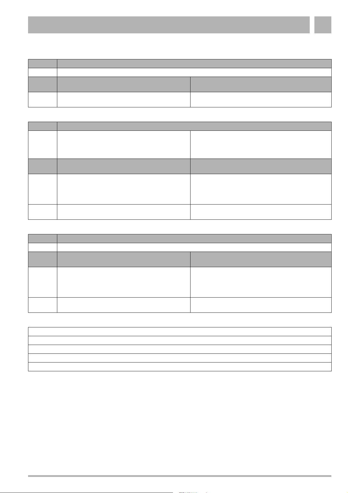
Servicing 5
Code Meaning
9U KIM defective
Possible
cause
1 Kim connected incorrectly or KIM defective Check the KIM connector and fan connector.
Code Meaning
E with
any
character
but P
Possible
cause
1 Regulating device may have to cope with interference – Check if for example induction fields interfere with the
2 UBA may be defective – Press reset. If fault code remains then try to temporarily
UBA defective
Action
If the connectors are fine then contact Boulter Buderus
Action
regulating device
– Check if the are any peaks in the electrical network
caused by maybe windmills or a power generator
connect a different UBA (see subsection 5.3.3)
Code Meaning
EP Non compatible UBA fitted
Possible
cause
1 Regulating device may have to cope with interference – Check if for example induction fields interfere with the
2 Kim connected incorrectly or KIM defective – Check the KIM connector and fan connector. If the
Problem: No heating, despite that there is a demand for heat and the boiler is operational
– Check regulating device configuration and/ or the wiring
– Check the wiring between the regulating device and the UBA (see subsection 5.3.6)
– Check all the wiring
– Check the UBA and replace if necessary (see subsection 5.3.3)
Action
regulating device
– Check if the are any peaks in the electrical network
caused by maybe windmills or a power generator
connectors are fine then contact Boulter Buderus
Subject to modifications resulting from technical improvements! Boulter Buderus Ltd. • http://www.boulter-buderus.co.uk
Installation and maintenance instructions for wall-mounted condensing gas boiler Buderus 600 - 11R/19R/24R • 05/2004 39
Page 40

Servicing5
5.3 Checking and replacing parts
5.3.1 Checking the flue gas sensor
z Detach plug-and-socket connection on cable to flue gas
sensor. Ensure that no cable is earthed (grounded) at any
point.
z Allow the flue gas sensor to cool down. Activation
temperature: Buderus 600 - 11R / 19R / 24R: 105 °C
z Check flue gas sensor for continuity. If continuity is not
present, the flue gas sensor is defective.
z Replace any flue gas sensor found to be defective.
Ensure you use only genuine Boulter Buderus spare parts.
z If the flue gas sensor is working correctly, plug it in once
more.
5.3.2 Replacing the flue gas sensor
z Unscrew the flow-backup mounting.
z Detach the cable plug at the flue gas sensor.
z Loosen both retaining screws on the flue gas sensor.
z Remove the flue gas sensor and replace with a new unit
(fig. 38).
z Retighten the retaining screws.
z Reconnect the cable plug.
z Screw the mounting into place.
5.3.3 Replacing the UBA
z Disconnect the system from the power supply.
z Loosen the two screws on the UBA (fig. 39, item 1).
z Carefully turn the UBA around with the backside facing up
(fig. 40).
z Note the position of the cable plugs, disconnect all cable
plugs.
z Fit a new UBA.
z Reconnect all plug-in cables to their correct sockets.
z Turn the UBA around and place back onto the bracket.
z Tighten the two screws.
z Connect system to mains power supply.
Fig. 38 Buderus 600 - 11R / 19R / 24R :
replacing the flue gas sensor
1
Fig. 39 Replacing the UBA
Fig. 40 Backside of the UBA
Subject to modifications resulting from technical improvements! Boulter Buderus Ltd. • http://www.boulter-buderus.co.uk
40 Installation and maintenance instructions for wall-mounted condensing gas boiler Buderus 600 - 11R/19R/24R • 05/2004
Page 41
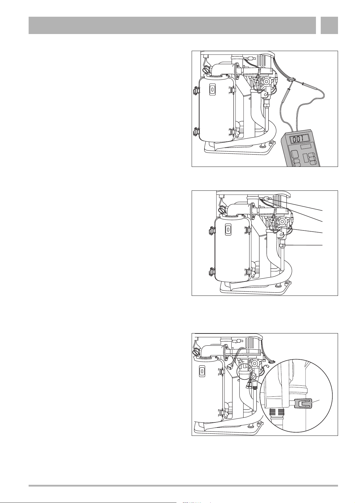
Servicing 5
5.3.4 Checking the fan
z Set the mains switch to “0”.
z Disconnect the fan's plug and socket connection.
z Connect a multimeter (230 V AC).
z Turn the mains power switch to “I”.
z Take voltage reading at measuring device.
If the voltage reading is 230 V, the power supply is in order.
z Set the mains switch to “0”.
z If the power supply is in order, plug the unit in once more.
z Turn the mains power switch to “I”.
z If the fan now fails to run, it must be replaced.
z If the fan runs at only partial load (i.e. effective operation of
the boiler is not possible), troubleshooting should start at
the connection cable to the UBA or UBA.
5.3.5 Replacing the fan
Fig. 41 Checking the fan
z Shut the gas valve.
z Disconnect the system from the power supply.
z Disconnect the fan, using the plug and socket from the
power supply (fig. 42, item 1), loosen the UBA control line
at the fan (fig. 42, item 2) and the gas burner fitting (fig. 42,
item 3).
z Loosen the union nut (fig. 42, item 4) on the gas burner
fitting.
z Push the safety plate out of the way (fig. 43, item 1).
z Turn air suction tube and pull off from below.
1
2
3
4
Fig. 42 Replacing the fan on the 600 Series:
loosen plug and union nut
1
Fig. 43 Replacing the fan on the 600 Series:
remove the air suction tube
Subject to modifications resulting from technical improvements! Boulter Buderus Ltd. • http://www.boulter-buderus.co.uk
Installation and maintenance instructions for wall-mounted condensing gas boiler Buderus 600 - 11R/19R/24R • 05/2004 41
Page 42

Servicing5
z Swivel the gas combination unit forward (fig. 44, item 1)
z Remove the gas combination unit from its bayonet
connector and pull upwards to detach (fig. 44, item 2).
z Detach the fan by loosening the 2 x 2 screws on the
connection unit.
z Replace the fan.
z Refit by following the above procedure in reverse.
2
Fig. 44 Replacing the fan on the 600 Series:
remove the gas connection unit
1
NOTE
Once installation has been completed
successfully, carry out leak testing as per
subsection 2.1.1.
5.3.6 Checking the wiring connections of the UBA
z Disconnect the system from the power supply.
z Loosen the two fixing screws and carefully turn the UBA
around (fig. 39, item 1, page 40).
z Check all cable terminals for tightness and
resecure/retighten as required.
z Turn the UBA around and place back onto the bracket.
z Tighten the two screws.
z Connect system to mains power supply.
Fig. 45 Replacing the fan on the 600 Series:
replace the fan
Fig. 46 Checking the wiring connections of the UBA
Subject to modifications resulting from technical improvements! Boulter Buderus Ltd. • http://www.boulter-buderus.co.uk
42 Installation and maintenance instructions for wall-mounted condensing gas boiler Buderus 600 - 11R/19R/24R • 05/2004
Page 43
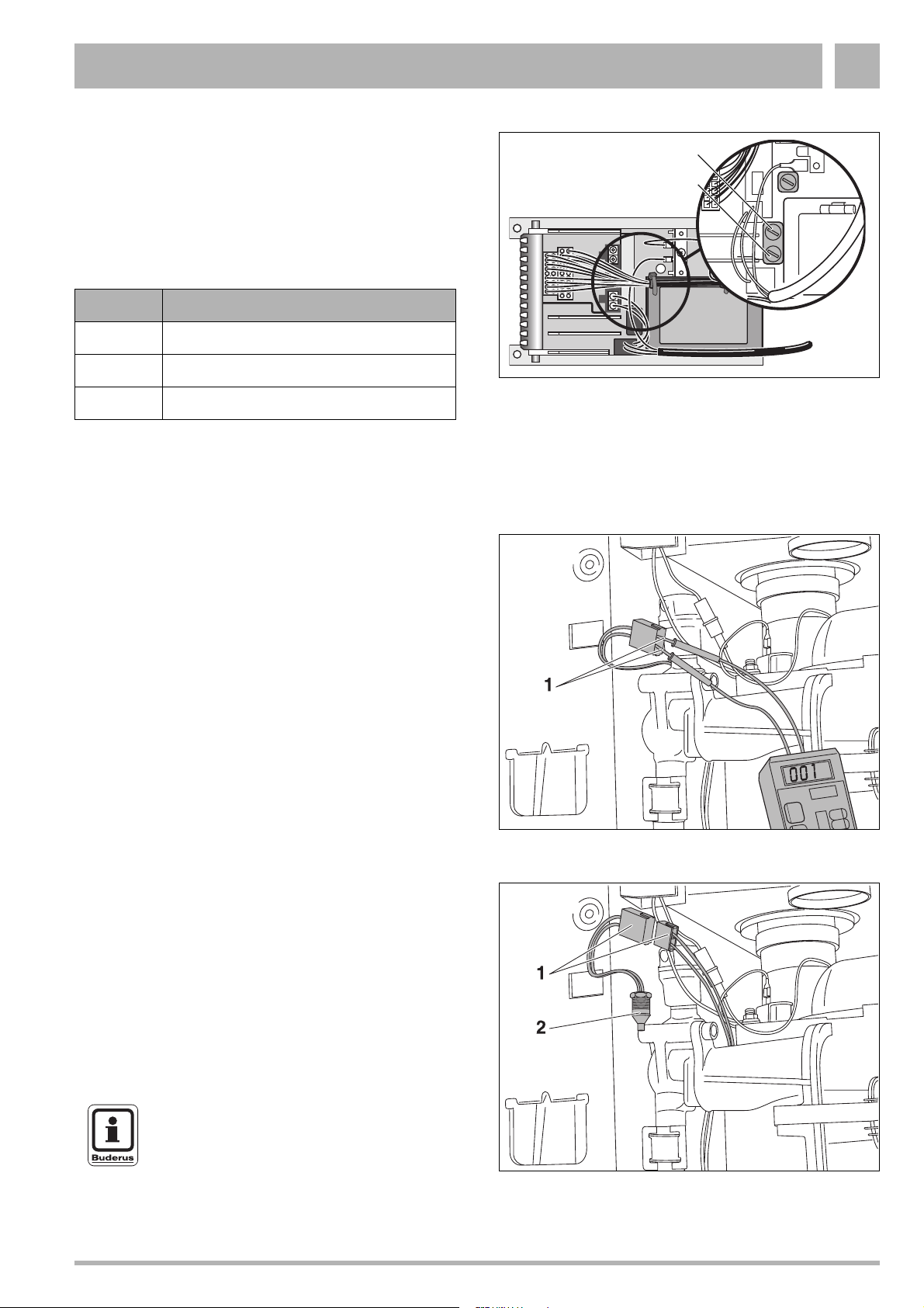
Servicing 5
5.3.7 Checking the miniature fuses
z Disconnect the system from the power supply.
z Loosen the two fixing screws and carefully turn the UBA
around.
z Check miniature fuses (fig. 47) for correct functioning,
or carry out visual inspection. If defective, fit new fuse
(1.25 AT).
Fuse Function
1 Hot surface ingitor
2 UBA, sensors, thermostat valve
3UBA
z Turn the UBA around and place back onto the bracket.
z Tighten the two screws.
z Connect system to mains power supply.
5.3.8 Checking the safety sensor
z Unplug cable connection from sensor.
z Measure resistance of sensor (fig. 48, item 1).
z Use a second-reading thermometer to measure the
temperature around the sensor.
z Compare readings with values shown in table 8 on
page 44. If there is any mismatch (i.e. > 5%), the sensor is
defective.
z If the sensor is working correctly, plug it in once more.
2
3
Fig. 47 Checking the miniature fuse
1
Fig. 48 Buderus 600 - 11R / 19R / 24R:
checking the safety sensor
5.3.9 Replacing the safety sensor
z Shut the servicing valve.
z Drain the Buderus 600 - 11R / 19R / 24R as per the
"Installation and Servicing Instructions".
z Loosen the plug-in connection (fig. 49, item 1).
z Unscrew the sensor (fig. 49, item 2) and replace with a new
unit.
z Plug in cable connection.
z Open servicing valves.
NOTE
Fill the Buderus 600 - 11R / 19R / 24R and
purge the system of air.
Fig. 49 Buderus 600 - 11R / 19R / 24R:
replacing the safety sensor
Subject to modifications resulting from technical improvements! Boulter Buderus Ltd. • http://www.boulter-buderus.co.uk
Installation and maintenance instructions for wall-mounted condensing gas boiler Buderus 600 - 11R/19R/24R • 05/2004 43
Page 44

Servicing5
5.3.10 Checking the safety sensor connection lead
Check to ensure that all plug-in connections on the sensor and
UBA are in order. Note that an incorrectly-inserted plug can
lead to the generation of error messages. Start up the boiler by
pressing the “reset” button.
z Set the mains switch to “0”.
z Disconnect the system from the power supply.
z Unplug cable connection from flow sensor.
z Disconnect 18-pin plug from UBA.
z Use a continuity tester to check the cable between the
plug-in connection and the 18-pin plug in the UBA.
The test should be carried out on connections 06-18 and
08-18 (fig. 50).
z If the cables are in order, plug them in.
z Connect system to mains power supply.
z Turn the mains power switch to “I”.
Fig. 50 Buderus 600 - 11R / 19R / 24R:
checking the safety sensor connection lead
5.3.11 Checking the flow sensor
z Unplug cable connection from sensor.
z Measure resistance of sensor (fig. 51, item 1).
z Use a second-reading thermometer to measure the
temperature around the sensor.
z Compare readings with values shown in table 8. If there is
any mismatch (i.e. > 5%), the sensor is defective.
z If the sensor is working correctly, plug it in once more.
1
Fig. 51 Buderus 600 - 11R / 19R / 24R:
checking the flow sensor
Temp.
[°C]
029,490
5 23,462 55 3,271.0
10 18,787 60 2,760.0
15 15,136 65 2,339.0
20 12,268 70 1,990.0
25 10,000 75 1,700.0
30 8,197 80 1,458.0
35 6,754 85 1,255.0
40 5,594 90 1,084.0
45 4,656 95 1,939.6
50 3,893 100 1,817.2
Table 8 Resistance values for hot water / boiler sensor
Resistance
[Ω]
(approximate values)
Temp.
[°C]
Resistance
[Ω]
Subject to modifications resulting from technical improvements! Boulter Buderus Ltd. • http://www.boulter-buderus.co.uk
44 Installation and maintenance instructions for wall-mounted condensing gas boiler Buderus 600 - 11R/19R/24R • 05/2004
Page 45

Servicing 5
5.3.12 Replacing the flow sensor
z Shut the servicing valve.
z Drain the Buderus 600 - 11R / 19R / 24R as per the
"Installation and Servicing Instructions".
z Loosen the plug-in connection (fig. 52, item 1).
z Unscrew the sensor (fig. 52, item 2) and replace with a new
unit.
z Plug in cable connection.
z Open servicing valves.
NOTE
Fill the Buderus 600 - 11R / 19R / 24R and
purge the system of air.
5.3.13 Checking the flow sensor connection lead
Check to ensure that all plug-in connections on the sensor and
UBA are in order. Note that an incorrectly-inserted plug can
lead to the generation of error messages. Start up the boiler by
pressing the “reset” button.
z Set the mains switch to “0”.
z Disconnect the system from the power supply.
z Unplug cable connection from flow sensor.
z Disconnect 20-pin plug from UBA.
z Use a continuity tester to check the cable between the
plug-in connection and the 20-pin plug in the UBA.
The test should be carried out on connections 05-20 and
18-20 (fig. 53).
z If the cables are in order, plug them in.
z Connect system to mains power supply.
z Turn the mains power switch to “I”.
1
1
2
Fig. 52 Buderus 600 - 11R / 19R / 24R:
replacing the flow sensor
UBA
1
11
Fig. 53 Buderus 600 - 11R / 19R / 24R:
checking the flow sensor connection lead
10
20
5.3.14 Checking the hot surface ingitor
z Disconnect the system from the power supply.
z Loosen the two fixing screws and carefully turn the UBA
around.
z Unplug and remove hot surface ingitor from UBA housing
(fig. 54).
z Check hot surface ingitor for free throughput.
If throughput is free, the hot surface ingitor is in order.
z If the hot surface ingitor is in order, plug the cable into the
UBA housing.
z Turn the UBA around and place back onto the bracket.
z Tighten the two screws.
z Connect system to mains power supply.
Subject to modifications resulting from technical improvements! Boulter Buderus Ltd. • http://www.boulter-buderus.co.uk
Installation and maintenance instructions for wall-mounted condensing gas boiler Buderus 600 - 11R/19R/24R • 05/2004 45
Fig. 54 Checking the hot surface ingitor
Page 46

Servicing5
5.3.15 Replacing the hot surface ingitor
z Disconnect the system from the power supply.
z Remove burner cover.
z Remove the earth (ground) lead from the hot surface
ingitor (fig. 55, item 1).
z Loosen the two screws on the UBA and carefully turn the
UBA around with the backside facing up.
z Unplug hot surface ingitor connection cable from UBA
(fig. 56).
z Loosen nut on clamp used to secure earth (ground) lead
(fig. 55, item 2).
z Detach retaining plate of hot surface ingitor (fig. 55, item 3)
and remove hot surface ingitor.
1
3
2
Fig. 55 Replacing the hot surface ingitor
5.3.16 Measuring the ionisation current
z Disconnect the system from the power supply.
z Loosen the plug-and-socket connector of the monitoring
cable and connect the measuring device in series.
Select the µA direct current range on the multimeter.
The multimeter must have a resolution of at least 1 µA.
z Reconnect the system to the power supply, make sure that
the system pump is running and turn the chimney-sweep
switch to “1”.
z Measure the ionisation current.
The ionisation current must be > 2 µA DC.
z Enter the reading on the report form.
z Disconnect the system from the power supply.
z Remove the measuring device and restore the
plug-and-socket connection to its original state.
z Turn the chimney-sweep switch to position “0”.
z Refit the cover for 2nd operating level.
z Reconnect the system to the power supply. When the
display shows “7”, press the service button to display “c”.
Press the "reset" button. The display shows “r”.
Fig. 56 Disconnect the plug-in cable from the UBA housing
Subject to modifications resulting from technical improvements! Boulter Buderus Ltd. • http://www.boulter-buderus.co.uk
46 Installation and maintenance instructions for wall-mounted condensing gas boiler Buderus 600 - 11R/19R/24R • 05/2004
Page 47

Servicing 5
5.3.17 Replacing the ionisation electrode
z Remove the air combination unit.
z Loosen the plug-and-socket connection of the ionization
electrode.
z Loosen screw (fig. 57, item 1) by a half-turn and slide bar
to remove.
z Pull electrode to remove, and fit new unit.
z Reassemble by following the above procedure in reverse.
Fig. 57 Replacing the ionisation electrode
5.3.18 Checking KIM connections
z Locate Kim on the side of the UBA bracket.
z Check if 4 pin connector (fig. 58, item 1) is fitted and
secure.
1
NOTE
This is not a servicable part and any fault
identified with this component, contact Boulter
Buderus.
1
Fig. 58 KIM connections
Subject to modifications resulting from technical improvements! Boulter Buderus Ltd. • http://www.boulter-buderus.co.uk
Installation and maintenance instructions for wall-mounted condensing gas boiler Buderus 600 - 11R/19R/24R • 05/2004 47
Page 48
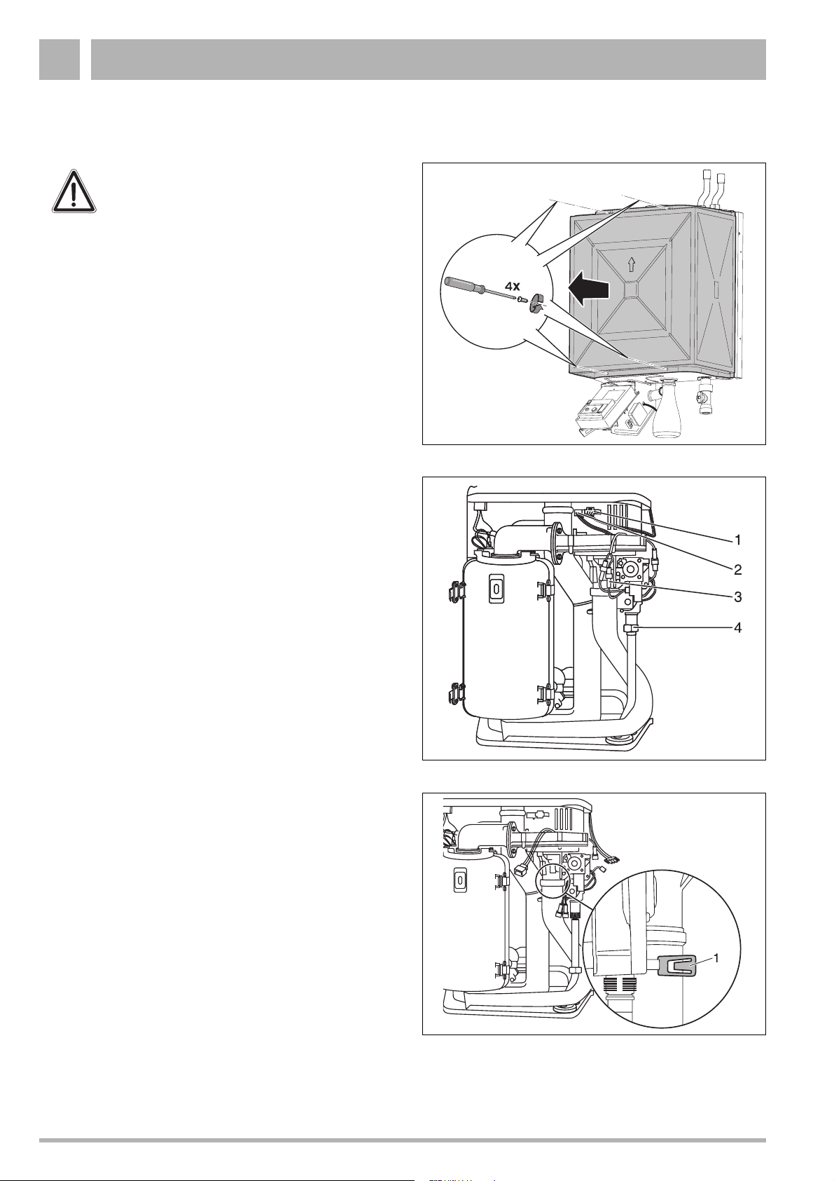
Conversion to another type of gas6
6 Conversion to another type of gas
WARNING!
Work on components in contact with gas must
only be carried out by a registered CORGI
engineer.
Switch off the heating boiler
z Disconnect the system from the power supply.
z Close the gas service valve.
z Loosen the 4 crosshead screws on the ventilation cover
(fig. 59).
z Remove the ventilation cover.
Fig. 59 Unscrew ventilation cover
z Loosen union nut on gas valve assembly (fig. 60, item 4).
z Release plug-in connection of fan power lead (fig. 60,
item 1), burner-control unit fan control lead (fig. 60, item 2)
and gas-burner assembly (fig. 60, item 3).
z Push safety plate out of way (fig. 61, item 1).
z Turn air suction tube and pull off from below.
Fig. 60 Loosen the union nut and remove the cable
Fig. 61 Remove safety plate
Subject to modifications resulting from technical improvements! Boulter Buderus Ltd. • http://www.boulter-buderus.co.uk
48 Installation and maintenance instructions for wall-mounted condensing gas boiler Buderus 600 - 11R/19R/24R • 05/2004
Page 49

Conversion to another type of gas 6
sz Swivel the air combination unit forwards (fig. 62, item 1).
z Pull the air combination unit up and out of the bayonet
connector (fig. 62, item 2) and remove via the front of the
unit.
2
1
Type of gas
supply
Natural gas H
(G20)
Propane P 3.40 4.15 Standard
Table 9 Gas-nozzle diameter
Replacing a gas nozzle
WARNING!
Conversion to another gas type is
implemented by installing/removing a gas
nozzle (fig. 63, item 3) of the appropriate gas
nozzle diameter (table 9).
z Undo the three screws (fig. 63, item 2) on the long side of
the gas fitting.
z Remove the gas nozzle and insert the correct gas nozzle
for the new gas type.
z Insert new seal (fig. 63, item 4).
z Remount all components in the reverse sequence.
z Cover stickers (fig. 64, item 1) with the new stickers
(2 pieces, included in conversion kit).
Gas nozzles ∅ [mm]
11R 19R/24R
5.55 6.5 Standard
Venturi
tubes
Fig. 62 Remove the air combination unit
Starting up
z Start up the appliance following the procedure described in
the mounting and maintenance instructions.
z Include all seal areas concerned during mounting in the
gas-tightness check when in operation.
z Refit all covers.
Subject to modifications resulting from technical improvements! Boulter Buderus Ltd. • http://www.boulter-buderus.co.uk
Fig. 63 Replacing a gaz nozzle
1
Fig. 64 Place new stickers
1
Installation and maintenance instructions for wall-mounted condensing gas boiler Buderus 600 - 11R/19R/24R • 05/2004 49
Page 50
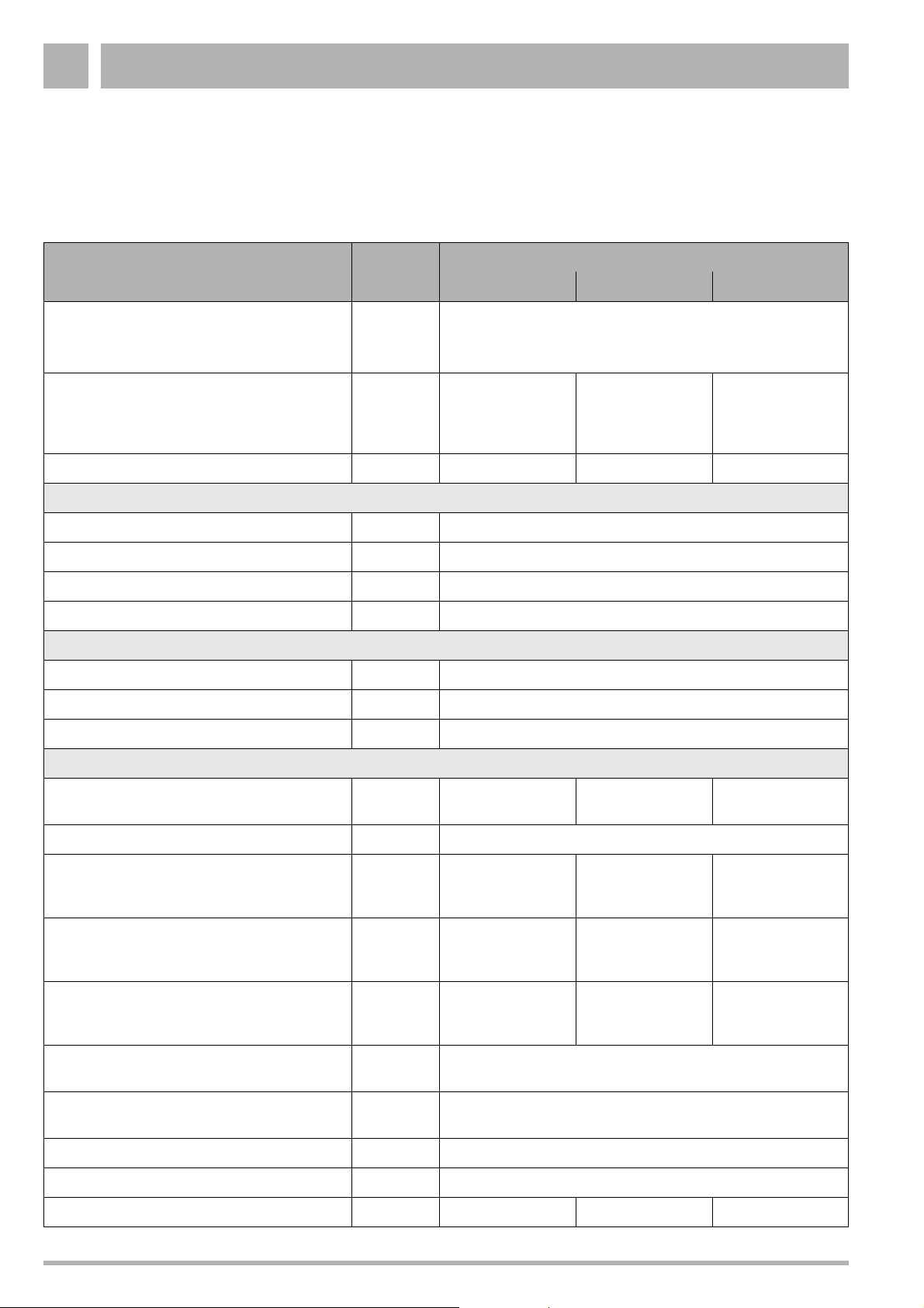
Appendix7
7 Appendix
7.1 Technical specifications
Dimensions Unit
Type of gas supply as established in
EN 437 (GB)
Rated heating capacity for system
temperature (modulating from 30° to 100°)
Heating curve 75/60 °C
Heating curve 40/30 °C
Seasonal efficiency (SEDBUK) % 90.3 90.3 90.2
Central heating installation
Heating water temperature °C 40 - 80
∆T at residual head of 200 mbar K <20
Max. operating overpressure of boiler bar 3.0
Volume heat exchanger heating circuit l 1.0
Pipe connections
Gas G½" (outside) / R½" (inside)
Heating water G¾" (device) / Ø 22 mm (accessory)
kW
kW
600 Series Buderus wall-mounted condensing gas boiler
11R 19R 24R
GB II
(natural gas H, propane P)
4.3 - 10.0
4.9 - 11.0
20 mbar, 37 mbar
2H3P
8.6 - 17.4
9.7 - 19.0
8.6 - 22.0
9.7 - 24.0
Condensate-water outlet mm Ø 21.5
Flue gas values
Condensate water quantity, natural gas,
40/30 °C
pH value of condensate water approx. 4.1
Flue gas mass-flow rate
Full load
Part-load
Flue gas temperature, full load
Heating curve 75/60 °C
Heating curve 40/30 °C
Flue gas temperature, part-load
Heating curve 75/60 °C
Heating curve 40/30 °C
full load, natural gas
CO
2
standard test gas G20 % 9.2
full load, natural gas
CO
2
standard test gas G31 propane % 10.3
Standard emission factor CO mg/kWh <22
Standard emission factor NO
Max. pressure drop permitted Pa 35 60 100
x
l/h 0.7 1.3 1.6
g/s
g/s
°C
°C
°C
°C
mg/kWh <30
4.9
2.2
75
50
65
40
8.4
4.3
85
55
70
45
10.6
4.3
95
55
70
45
Subject to modifications resulting from technical improvements! Boulter Buderus Ltd. • http://www.boulter-buderus.co.uk
50 Installation and maintenance instructions for wall-mounted condensing gas boiler Buderus 600 - 11R/19R/24R • 05/2004
Page 51

Appendix 7
Dimensions Unit
Flue-gas system
Type of flue gas connection C
Diameter of flue gas system mm 60/100
Electrical data
Mains connection voltage V 230
Electrical power consumption
Full/Part load W 40/25 40/25 40/25
Electrical protection rating IPX4D
Boiler dimensions and weight
Height x Width x Depth mm 700 x 460 x 290
Weight (without casing) kg 23.5 23.5 23.5
Casing kg 5.5 5.5 5.5
600 Series Buderus wall-mounted condensing gas boiler
11R 19R 24R
, C33, C
13
53
Subject to modifications resulting from technical improvements! Boulter Buderus Ltd. • http://www.boulter-buderus.co.uk
Installation and maintenance instructions for wall-mounted condensing gas boiler Buderus 600 - 11R/19R/24R • 05/2004 51
Page 52

Appendix7
7.2 Short list of spare parts
The following are parts commonly required due to damage or expendability. Their failure or absence is likely to affect safety or
performance of this appliance. For a pictorial representation of the part see the respective position number on the exploded view
pictures on page 10.
Pos. Art. no. Description
10 75131 Casing complete
20 75130 Door
30 38470 Ventilation cover
40 38092 Bracket
50 77465 Concentric adaptor
60 38496 Clip adaptor
70 77464 Lipring 100 mm
80 73366 Fan
90 73565s Sealing fan / venturi (set of 5 pieces)
73566s Sealing ventilator (set of 5 pieces)
100 73563 Lipring 60 mm
110 73743 Flue gas pipe
120 73630 Condensate collector
130 73579 Seal flue gas pipe
140 73376 Flue gas sensor
150 75969 Condensate trap
160 73573 Suction pipe
170 73574 Lipring 50 mm
180 73278 Gas valve
190 38355 Rectifier
200 73567 Venturi 11 kW
200 73568 Venturi 19-24 kW
210 76680 Gas pipe
220 76681 Gas service valve
230 75968s Pipe return-flow top (set of 2 pieces)
240 75970 Pipe connection
75971 Drain pipe condensate trap
250 38602s Clip sanitary pipe (set of 5 pieces)
260 75966 Return pipe
270 75967 Drain cock
280 73583 Connection return
290 38352 Sensor
300 75965 Flow pipe
310 73581 Connection supply
320 73582s
330 38618 Automatic air vent
340 73580s O-ring (set of 10 pieces)
350 73584s Lipring (set of 2 pieces)
360 38323 Safety sensor
370 38478s Sealing ring (set of 10 pieces)
380 73611 Backpart heat exchanger
390 73578 Seal heat exchanger
400 73514 Insulation backpart heat exchanger
410 73593 Burner 11 kW
410 Burner 19 kW
410 73594 Burner 24 kW
420 73571s Sealing burner (set of 5 pieces)
Hairpin heat exchanger
(set of 2 pieces)
Pos. Art. no. Description
430 73612 Heat exchanger helix
440 73587 Combustion divider
450 73513 Insulation front heat exchanger
460 73610 Frontpart heat exchanger
470 38009 Sight glass
470 73576 Sight glass
480 75132s Fasteners (set of 2 pieces)
490 38324 UBA
500 38340 Mains switch
510 78105 Hot surface ignitor
520 38320 Ionisation electrode
530 73367 Cable fan
540 78109 Cable harness
560 78079 RTH converter 230V
550 - Frame
78110 Kim 163 (11 kw)
78111 Kim 164 (19 kw)
78112 Kim 165 (24 kw)
36404s Plate screw (set of 10 pieces)
36406s Screw 6x5/8" (set of 5 pieces)
38456 Seal ventilation cover
38458s Assembly casing block (set of 2 pieces)
38460s Casing clamp (set of 5 pieces)
38462s Air seal bush (set of 5 pieces)
38463s Air seal bush (set of 4 pieces)
38474s
38475s Clip (set of 5 pieces)
73591s
79058s Pull relief (set of 5 pieces)
79084s Sealing ring (set of 2 pieces)
75300 Thermomanometer
73572s Screw M5 ( set of 10 pieces)
73054
73515 Insulation divider
73560 Cap
73586s Seal
73053 Clip suction pipe
73570 Gas air supply
73056s Clip (set of 5 pieces)
73368s Sealing ignitor (set of 10 pieces)
73488s Gasket (set of 5 pieces)
73569s Sealing venturi / gasket
75301 230V cable
75882 Swivel dreg with pinchring
73561 Sealing
Clip CH tank (2) / clip sensorhousing
(2)
O-ring condensate trap
(set of 5 pieces)
Bracket ionisation electr. and glow
ignitor
Subject to modifications resulting from technical improvements! Boulter Buderus Ltd. • http://www.boulter-buderus.co.uk
52 Installation and maintenance instructions for wall-mounted condensing gas boiler Buderus 600 - 11R/19R/24R • 05/2004
Page 53
Reports 8
8Reports
8.1 Start-up report
z Please check off the start-up tasks carried out and enter
the corresponding readings.
Initial start-up tasks Remarks or measurement readings
1. Note down gas characteristics:
Wobbe index
Operating heat value
2. Inspect to check for leaks
(See section 2.1.1 on page 20)
3. Check combustion air/flue gas connection
(See section 2.1.3 on page 21)
4. Checking the boiler equipment (change to another type of gas if
necessary) (See section 2.1.4 on page 21)
5. Carry out adjustment settings
(See section 2.1.5 on page 22)
6. Measure the gas connection pressure (flow pressure)
(See section 2.1.7 on page 23)
7. Checking and adjusting the gas/air -ratio
CO
-content: at full load
2
(See section 2.1.8 on page 23)
8. Leak test in operational condition
9. Measure carbon monoxide content (CO), vacuum
(See section 2.1.9 on page 24)
at part load
_____________________ kWh/m
_____________________ kWh/m
_____________________ mbar
_____________________ Pa
_____________________ %
_____________________ %
_____________________ ppm
3
3
10. Function testing
Measuring the ionisation current
(See section 2.1.10 on page 24)
11. Fit the boiler casing
12. Instruct the user. Fill in Benchmark log book.
Hand over documentation.
(See section 2.1.11 on page 25)
13. Confirm initial start-up
Confirmation of initial start-up by qualified service technician
(Company stamp, signature)
Subject to modifications resulting from technical improvements! Boulter Buderus Ltd. • http://www.boulter-buderus.co.uk
Installation and maintenance instructions for wall-mounted condensing gas boiler Buderus 600 - 11R/19R/24R • 05/2004 53
_____________________ µA
Page 54

Reports8
8.2 Inspection and maintenance reports
The inspection and maintenance reports provide an overview
of all the tasks and operations carried out.
See also Section 3: "Inspection“ on page 26 or Section 4:
"Maintenance“ on page 27.
Inspection tasks Date: _____________ Date: _____________
1. Check general state of system
2. Visual inspection and function check of system
3. Check gas- and water-bearing components for:
- leaks;
- signs of corrosion;
- signs of ageing.
4. Take system out of service and check the burner, heat exchanger
and siphon for signs of dirt and soiling.
(See section 4.1.1 on page 27)
5. Check the burner, hot surface ignitor and ionisation electrode,
after disconnecting the system.
(See section 4.1.1 on page 27)
Please check off the inspection and/or requirement-related
maintenance tasks carried out and enter the corresponding
readings.
z Sign details of inspection and maintenance tasks,
indicating date carried out.
Use only original replacement parts.
6. Measuring the ionisation current
(See section 2.1.10 on page 24) _________________ µA _________________ µA
7. Measure the gas connection pressure (flow pressure)
(See section 2.1.7 on page 23) ________________ mbar ________________ mbar
8. Check the gas-air ratio
(See section 2.1.8 on page 23) _________________ Pa _________________ Pa
9. Gas leak test in operational condition
(See section 2.1.1 on page 20)
10. Measure the carbon monoxide content (CO), vacuum
(See section 2.1.9 on page 24) ________________ ppm ________________ ppm
11. Pressure-testing of heating system:
- admission pressure of expansion tank
(see installation instructions supplied with expansion tank)
- Filling pressure
12. Check ventilation and flue gas conduits for correct functioning and
safety
13. Check requirement-related adjustment settings of control device
(see documentation supplied with control device)
14. Final check of inspection tasks,
with record kept of measurement readings and test results
________________ mbar
________________ mbar
________________ mbar
________________ mbar
15. Confirm inspection carried out by qualified service engineer
and fill out the Benchmark
Company stamp / Date / Signature)
Subject to modifications resulting from technical improvements! Boulter Buderus Ltd. • http://www.boulter-buderus.co.uk
54 Installation and maintenance instructions for wall-mounted condensing gas boiler Buderus 600 - 11R/19R/24R • 05/2004
Page 55
Reports 8
Date: _________ Date: ___________ Date: ___________ Date: ___________ Date: ___________
_______________ µA _______________ µA _______________ µA _______________ µA _______________ µA
_____________ mbar _____________ mbar _____________ mbar _____________ mbar _____________ mbar
_______________ Pa _______________ Pa _______________ Pa _______________ Pa _______________ Pa
______________ ppm ______________ ppm ______________ ppm ______________ ppm ______________ ppm
_____________ mbar
_____________ mbar
_____________ mbar
_____________ mbar
_____________ mbar
_____________ mbar
_____________ mbar
_____________ mbar
_____________ mbar
_____________ mbar
Subject to modifications resulting from technical improvements! Boulter Buderus Ltd. • http://www.boulter-buderus.co.uk
Installation and maintenance instructions for wall-mounted condensing gas boiler Buderus 600 - 11R/19R/24R • 05/2004 55
Page 56

Reports8
Requirement-related maintenance tasks Date: _____________ Date: _____________
1. Clean heat exchanger, burner and condensate trap
(See section 4.1 on page 27)
2. Check and adjust the gas-air ratio
-content: at full load
CO
2
at part load
(See section 2.1.8 on page 23)
3. Confirm servicing work
Confirmation of servicing carried out by qualified technician
Company stamp, signature)
______________________
______________________
______________________
Pa
______________________
%
______________________
%
______________________
Pa
%
%
Subject to modifications resulting from technical improvements! Boulter Buderus Ltd. • http://www.boulter-buderus.co.uk
56 Installation and maintenance instructions for wall-mounted condensing gas boiler Buderus 600 - 11R/19R/24R • 05/2004
Page 57

Reports 8
Date: ___________ Date: ___________ Date: ___________ Date: ___________ Date: ___________
___________________
____________________
____________________
Pa
___________________
%
____________________
%
____________________
Pa
___________________
%
____________________
%
____________________
Pa
___________________
%
____________________
%
____________________
Pa
___________________
%
____________________
%
____________________
Pa
%
%
Subject to modifications resulting from technical improvements! Boulter Buderus Ltd. • http://www.boulter-buderus.co.uk
Installation and maintenance instructions for wall-mounted condensing gas boiler Buderus 600 - 11R/19R/24R • 05/2004 57
Page 58

Notes
Subject to modifications resulting from technical improvements! Boulter Buderus Ltd. • http://www.boulter-buderus.co.uk
58 Installation and maintenance instructions for wall-mounted condensing gas boiler Buderus 600 - 11R/19R/24R • 05/2004
Page 59

Notes
Subject to modifications resulting from technical improvements! Boulter Buderus Ltd. • http://www.boulter-buderus.co.uk
Installation and maintenance instructions for wall-mounted condensing gas boiler Buderus 600 - 11R/19R/24R • 05/2004 59
Page 60

Heating system specialist:
Boulter Buderus Ltd.
Magnet House
30 Whitehouse Road
Ipswich
Suffolk, IP1 5JA
Telephone: 01473 241555
Fax: 01473 241321/463411
http://www.boulter-buderus.co.uk
e-mail: info@boulter-buderus.co.uk
721.229A - 4066 - 05/2004
 Loading...