

Page 1

7210 1300 - 02/2006 GB(EN) For trade use
Servicing manual
Gas wall hung boiler condensing
600 Series - 11S / 19S / 24S / 24C
GB122
Please read thoroughly before attempting to diagnose fault
Page 2
List of contents
Preface
1 Messages – Universal Automatic Burner
(UBA) . . . . . . . . . . . . . . . . . . . . . . . . . . . . . . 3
1.1 UBA status display . . . . . . . . . . . . . . . . . . . . . . . . 3
1.2 UBA operating level 1.5 . . . . . . . . . . . . . . . . . . . . . 4
1.3 Service tool . . . . . . . . . . . . . . . . . . . . . . . . . . . . . . 4
1.4 Operating messages . . . . . . . . . . . . . . . . . . . . . . . 5
1.5 Fault messages . . . . . . . . . . . . . . . . . . . . . . . . . . . 6
2 Faults that the UBA does not display . . . 8
3 Troubleshooting . . . . . . . . . . . . . . . . . . . . . 9
3.1 Troubleshooting tasks . . . . . . . . . . . . . . . . . . . . . 47
3.1.1 Unblocking the 600 Series 11S / 19S / 24S / 24C 47
3.1.2 Chimney-sweep mode . . . . . . . . . . . . . . . . . . . . . 47
3.1.3 Removing and refitting the outer casing . . . . . . . 48
3.1.4 Removing and refitting the combustion-
chamber cover . . . . . . . . . . . . . . . . . . . . . . . . . . . 48
3.1.5 Checking the exhaust-gas sensor . . . . . . . . . . . . 49
3.1.6 Replacing the exhaust-gas sensor . . . . . . . . . . . 49
3.1.7 Checking the air intake and outlet openings . . . . 50
3.1.8 Replacing the UBA . . . . . . . . . . . . . . . . . . . . . . . 50
3.1.9 Checking the fan . . . . . . . . . . . . . . . . . . . . . . . . . 51
3.1.10 Replacing the fan . . . . . . . . . . . . . . . . . . . . . . . . . 51
3.1.11 Checking the wiring connections of the UBA . . . . 53
3.1.12 Checking the miniature fuses . . . . . . . . . . . . . . . 53
3.1.13 Checking the connections for the second
solenoid valve, modulating pump and floor
thermostat switching contact . . . . . . . . . . . . . . . . 53
3.1.14 Checking the circulation pump . . . . . . . . . . . . . . 54
3.1.15 Replacing the circulation pump . . . . . . . . . . . . . . 54
3.1.16 Checking the safety sensor . . . . . . . . . . . . . . . . . 55
3.1.17 Replacing the safety sensor . . . . . . . . . . . . . . . . 55
3.1.18 Checking the safety sensor connection lead . . . . 55
3.1.19 Checking the feed sensor . . . . . . . . . . . . . . . . . . 56
3.1.20 Replacing the feed sensor . . . . . . . . . . . . . . . . . . 56
3.1.21 Checking the feed sensor connection lead . . . . . 56
3.1.22 Checking the domestic hot water /
mains water supply . . . . . . . . . . . . . . . . . . . . . . . 57
3.1.23 Changing the domestic hot water /
mains water supply . . . . . . . . . . . . . . . . . . . . . . . 58
3.1.24 Checking the hot surface ingitor . . . . . . . . . . . . . 59
3.1.25 Replacing the hot surface ingitor . . . . . . . . . . . . . 59
3.1.26 Checking the gas-burner control system for
correct activation . . . . . . . . . . . . . . . . . . . . . . . . . 60
3.1.27 Replacing the gas burner fitting . . . . . . . . . . . . . . 60
3.1.28 Checking and adjusting the gas-to-air ratio . . . . . 62
3.1.29 Measuring the ionisation current . . . . . . . . . . . . . 63
3.1.30 Replacing the ionisation electrode . . . . . . . . . . . . 63
3.1.31 Checking the three-way motorised valve for
correct operation . . . . . . . . . . . . . . . . . . . . . . . . . 64
3.1.32 Replacing the motorised valve body control valve 64
3.1.33 Replacing the three-way valve . . . . . . . . . . . . . . 65
3.1.34 Checking the ERC/RC connections to the UBA . 66
3.1.35 Replacing the terminal strip . . . . . . . . . . . . . . . . . 66
3.1.36 Checking connections at the ERC or RC . . . . . . 67
3.1.37 Replacing the room-temperature control device . 67
Important general instructions for use
This device should only be operated in accordance with its
designated use and the indications given in the servicing
instructions. All maintenance and repair operations must be
carried out by a qualified service technician.
Always operate in conjunction with original accessories, and
use only genuine spare parts. Other combinations of units,
accessories and consumables are only to be used if they
completely fulfil the specifications involved, and if system
performance and safety are not affected in any way.
Note that all the servicing tasks described here must be carried
out by a qualified maintenance firm. Work on gas pipes and
fittings must only be carried out by a CORGI registered
engineer.
Subject to technical modifications
As a result of our policy of constant development, there may be
small differences between illustrations, functional steps and
technical data.
The boiler meets the basic requirements of the
appropriate standards and directives.
Conformity has been substantiated by the
proper documents which - together with the
declaration of conformity - are filed with the
manufacturer.
BENCHMARK' Log Book
All Buderus gas boilers now include an Installation, Commissioning and Service record log book. The details of the log
book will be required in the event of any warranty work being
requested.
Please complete the appropriate section at each service visit.
REMEMBER: Please hand the log book back to the user.
Subject to modifications resulting from technical improvements! Buderus Ltd. • http://www.buderus-domestic.co.uk
2 Servicing manual for wall-mounted condensing gas boiler 600 Series 11S/19S/24S/24C • Issued 02/2006
Page 3
Messages – Universal Automatic Burner (UBA) 1
Buderus
U122 K
1 Messages – Universal Automatic Burner (UBA)
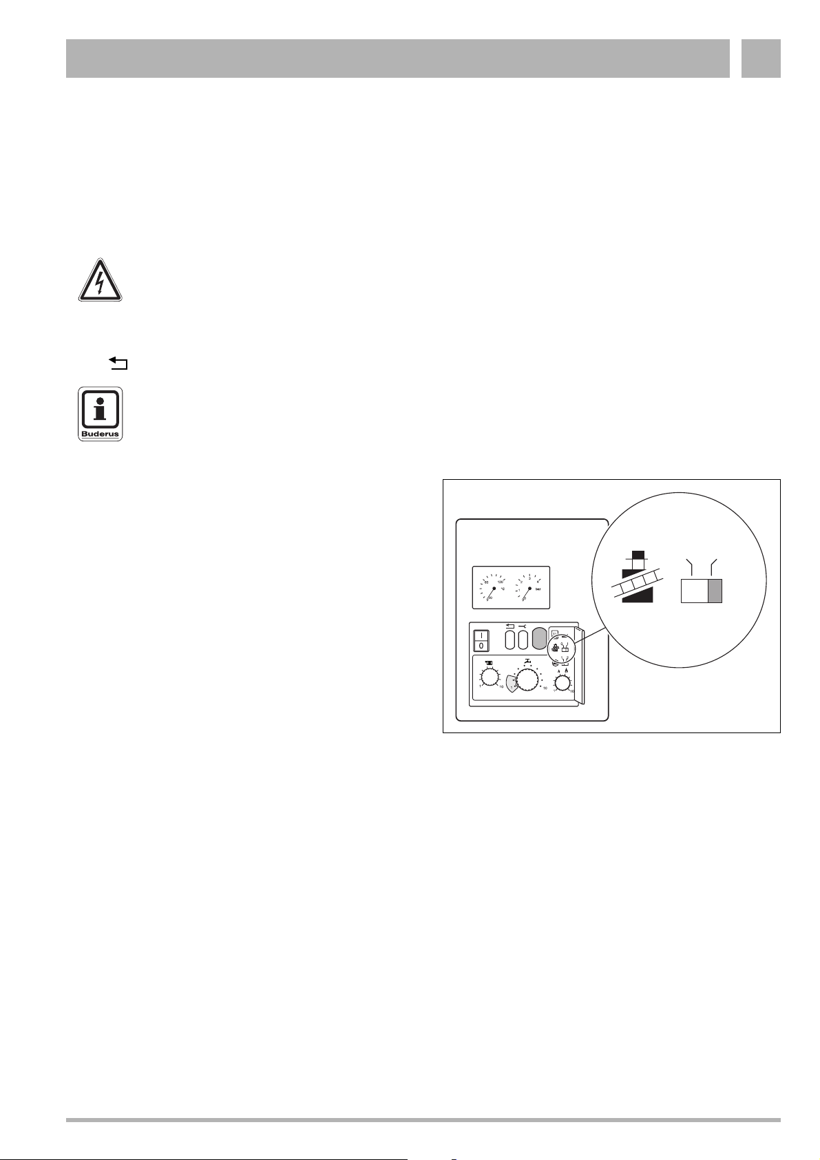
1.1 UBA status display
Operational condition and error messages appear on the
display of the Universal Automatic Burner (UBA).
The message consists of two characters.
The first character is displayed automatically.
Fig. 1 600 Series 11S / 19S / 24S / 24C: Display
To display the second character:
z Hinge the control panel cover to the left to open.
z Press the "Service" button.
Fig. 2 600 Series 11S / 19S / 24S / 24C:
Open the control panel cover
Fig. 3 "Service" button
Subject to modifications resulting from technical improvements! Buderus Ltd. • http://www.buderus-domestic.co.uk
Servicing manual for wall-mounted condensing gas boiler 600 Series 11S/19S/24S/24C • Issued 02/2006 3
Page 4
Messages – Universal Automatic Burner (UBA)1
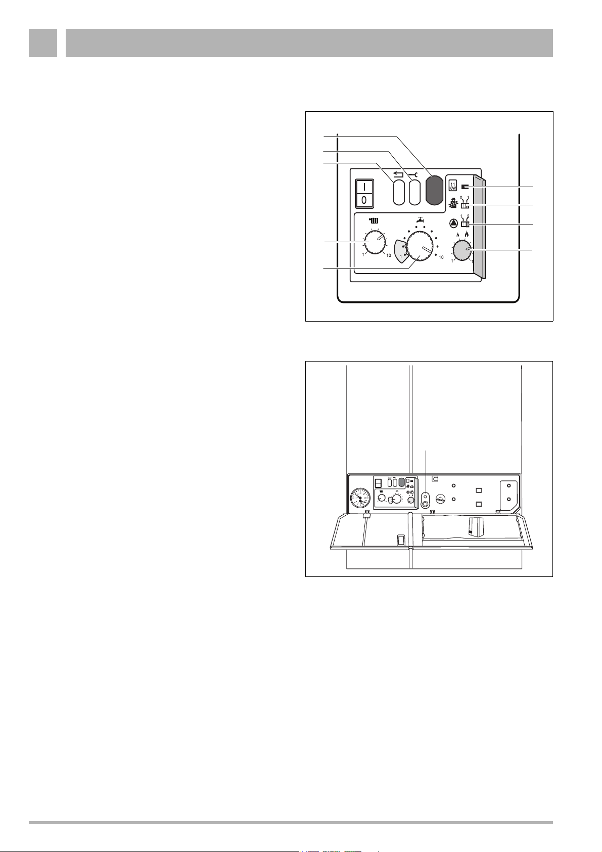
1.2 UBA operating level 1.5
UBA operating level 1.5 (fig. 4).
Key:
Item 1: Display
Item 2: Service button
Item 3: Reset button
Item 4: Boiler flow temperature
Item 5: Hot-water temperature
Item 6: Power adjustment
Item 7: Pump overrun switch
Item 8: Chimney-sweep switch
Item 9: 11 kW jumper
1
2
3
4
5
Fig. 4 UBA operating level 1.5
9
8
7
6
1.3 Service tool
The service tool allows you to determine the operating status
of the boiler, check components and carry out fast fault diagnosis.
z Open the cover at the front of the boiler unit and insert the
twin plug connector of the service tool into the sockets
provided (fig. 5, item 1).
1
11
KW
I
0
Fig. 5 Service tool connection
01
12
1
10
1
10
Subject to modifications resulting from technical improvements! Buderus Ltd. • http://www.buderus-domestic.co.uk
4 Servicing manual for wall-mounted condensing gas boiler 600 Series 11S/19S/24S/24C • Issued 02/2006
Page 5
Messages – Universal Automatic Burner (UBA) 1
1.4 Operating messages
Display after
Display
pressing the
service button
Meaning
-.
=.
0
A
C
H
L
U
y
A
H
y
600 Series 11S / 19S / 24S / 24C is ready for operation
Burner interval circuit, 10 min from burner start-up
Waiting for the three-way valve and/or pump to switch
Standby activated, 600 Series 11S / 19S / 24S / 24C ready to provide heat or hot water
Initial safety period: self-testing of UBA during burner start-up
Post- or pre-flushing period of fan unit
Flow temperature at adjustment setting
600 Series 11S / 19S / 24S / 24C running in heating mode
“Chimney-sweep” mode, flow-temperature controller bypassed,
600 Series 11S / 19S / 24S / 24C heating to previously-entered flow temperature
Normal heating mode
Service mode
600 Series 11S / 19S / 24S / 24C running in hot-water mode
H
r
Table 1 Displayed UBA operating messages
Normal hot water mode
Reset
Subject to modifications resulting from technical improvements! Buderus Ltd. • http://www.buderus-domestic.co.uk
Servicing manual for wall-mounted condensing gas boiler 600 Series 11S/19S/24S/24C • Issued 02/2006 5
Page 6
Messages – Universal Automatic Burner (UBA)1
1.5 Fault messages
Display
2
3
4
Display after
pressing the
service button
C
P
C
A
C
F
H
Trouble-
Meaning
Water flow
Safety sensor exceeds 100 °C page 10
Excessive temperature increase at safety sensor page 11
Air volume flow
Bad plug-in connection at cable loom, or damaged wiring page 12
Temperatures
Feed sensor above 100 °C page 13
F2 fuse malfunction, or exhaust-gas sensor tripped
Safety sensor exceeds 100 °C page 17
Dripping tap page 18
shooting
flow diagram
page 15
L
P
U
y
5
C
6
A
C
H
L
Short circuit in safety sensor page 19
Safety sensor, loose contact or defective page 20
Short circuit in feed sensor page 21
Feed sensor, loose contact or defective page 22
Communication
600 series has switched off after disconnection of diagnosis plug
Flame monitoring
F1 fuse defective, or no ionisation message after ignition page 24
Ionisation message, but no flame page 28
Flame dies out after gas valve is opened page 29
Flame goes out during warm-up phase page 30
page 23
Subject to modifications resulting from technical improvements! Buderus Ltd. • http://www.buderus-domestic.co.uk
6 Servicing manual for wall-mounted condensing gas boiler 600 Series 11S/19S/24S/24C • Issued 02/2006
Page 7
Messages – Universal Automatic Burner (UBA) 1
Display
7
8
9
Display after
pressing the
service button
A
C
F
H
L
y
A
Trouble-
Meaning
Mains voltage
Voltage in UBA too low or too high page 31
Mains voltage interrupted following a fault warning message page 32
F3 fuse defect, or UBA system error page 33
Voltage peaks in UBA page 34
UBA timer error page 35
General fault/gas-pressure
External switching contact, e.g. temperature monitor for floor heating, has
been tripped
System error
System error page 37
shooting
flow diagram
page 36
C
F, H, P
L
U
E
Any indication,
except
Incorrect cable connection at KIM, or KIM defective page 38
System error (UBA defective) page 39
Wiring to gas-burner assembly incorrect, or loose wiring connections
in UBA
KIM defective page 41
UBA system fault
UBA system fault
P
P
Table 2 Displayed UBA fault warning messages
Non-compatible UBA fitted page 42
page 40
Subject to modifications resulting from technical improvements! Buderus Ltd. • http://www.buderus-domestic.co.uk
Servicing manual for wall-mounted condensing gas boiler 600 Series 11S/19S/24S/24C • Issued 02/2006 7
Page 8

Faults that the UBA does not display2
2 Faults that the UBA does not display
Hot-water mode
Although the UBA is apparently ready for use, situations may
arise where a hot-water tap is opened and no hot water flows
out, or flows out for only a short period.
Troubleshooting flow diagram:
page 43/44.
Heating mode
Although the UBA is apparently ready for use, and the room
temperature has not yet reached the preset level, the
600 Series 11S / 19S / 24S / 24C wall-mounted condensing
gas boiler fails to go into heating mode.
Troubleshooting flow diagram:
page 45.
Subject to modifications resulting from technical improvements! Buderus Ltd. • http://www.buderus-domestic.co.uk
8 Servicing manual for wall-mounted condensing gas boiler 600 Series 11S/19S/24S/24C • Issued 02/2006
Page 9
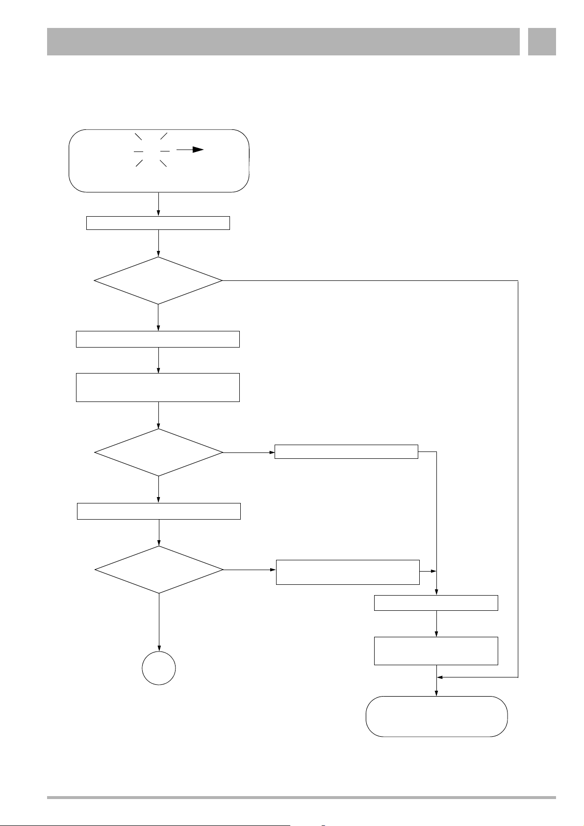
Troubleshooting 3
3 Troubleshooting
The following flow diagrams are provided for the purpose of
systematic troubleshooting.
Take the opportunity, while carrying out fault diagnosis, to
check that all that plugs and wiring terminals on the UBA are
connected correctly.
WARNING
Switch off the 600 Series 11S / 19S / 24S / 24C
BEFORE checking the connections.
Each time a fault has been rectified, push the “reset”
button " " to unblock the UBA and return it to standby mode.
NOTE
The system cannot be reset by disconnecting
at the master switch.
Certain troubleshooting tasks must be carried out with the
600 Series 11S / 19S / 24S / 24C in heating mode.
When doing so, the chimney-sweep switch should be set to "1"
(fig. 6).
Remember to return the chimney-sweep switch to “0” once
work is complete.
01
Fig. 6 Chimney sweeper switch on UBA
Subject to modifications resulting from technical improvements! Buderus Ltd. • http://www.buderus-domestic.co.uk
Servicing manual for wall-mounted condensing gas boiler 600 Series 11S/19S/24S/24C • Issued 02/2006 9
Page 10
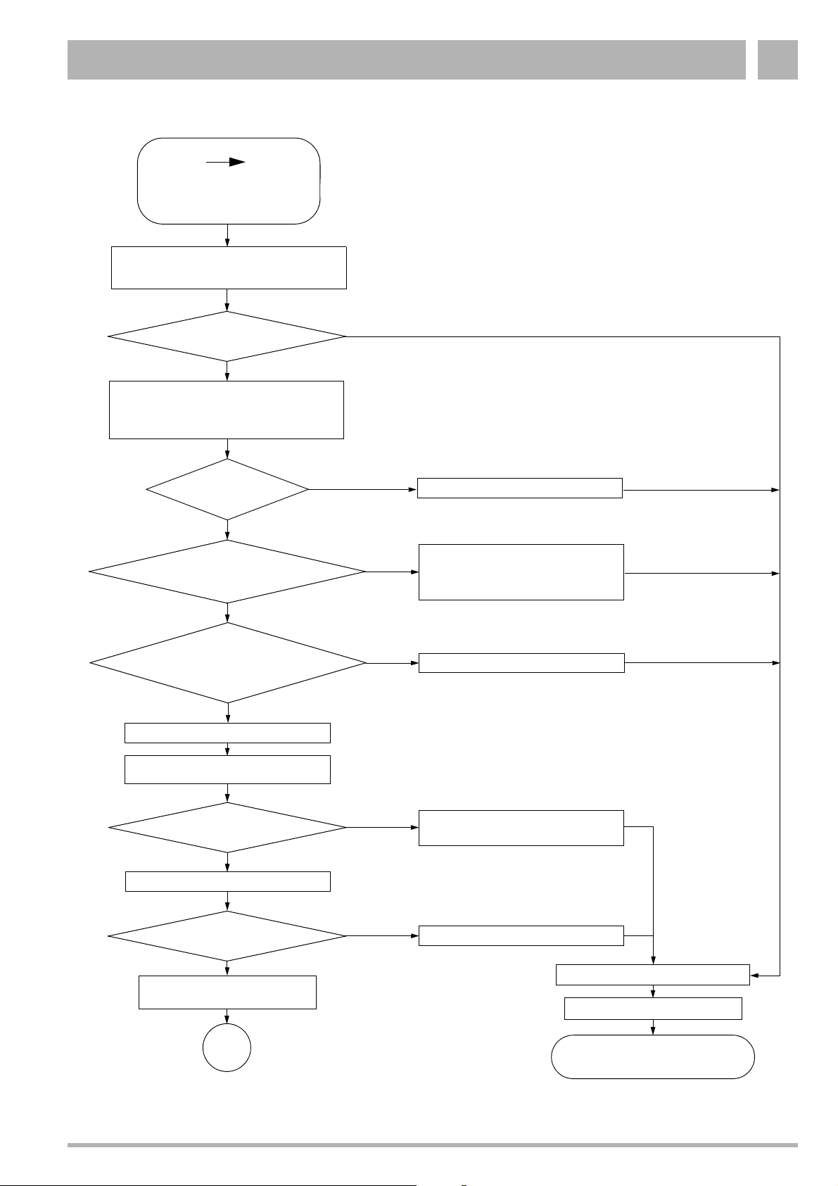
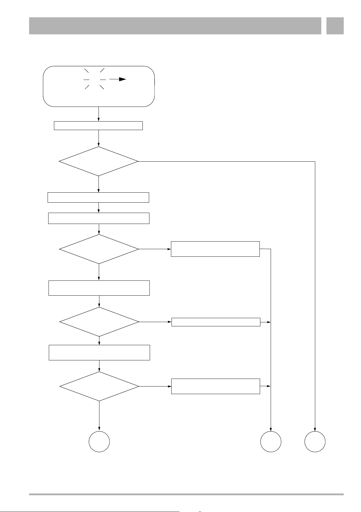
Troubleshooting3
2
Safety sensor temp. exceeds
100 °C
Wait approx. 30 sec for the boiler to return
automatically to normal operation
New fault warning message
2C?
Check system and heat exchanger, as
indicated in the installation and servicing
instructions, for signs of airlocks and dirt -
purge and/or clean as required
Are all
maintenance shutoff
valves open?
Is the water
pressure in the system at
least 1 bar?
C
Yes
Yes
No
No
No
Open maintenance shutoff valves
Fill up with water as indicated in the
installation and servicing instruc-
tions, and purge the system of air
Yes
Is at least one
thermostatic valve open (to
control the amount of water
circulating)?
Yes
Remove the casing (page 48)
Check safety sensor and wiring
(page 55)
Safety sensor OK?
Yes
Check circulation pump (page 54)
Circulation pump OK?
Yes
Filter to catch dirt fitted?
If yes, is it unclogged?
No
No
No
Open one thermostatic valve
Replace safety sensor (page 55)
Replace circulation pump (page 54)
Fit the casing (page 48)
"reset"
A
page 46
Fig. 7 Fault warning message 2C: Safety sensor temp. exceeds 100 °C
Subject to modifications resulting from technical improvements! Buderus Ltd. • http://www.buderus-domestic.co.uk
10 Servicing manual for wall-mounted condensing gas boiler 600 Series 11S/19S/24S/24C • Issued 02/2006
600 Series 11S / 19S / 24S / 24C
OK
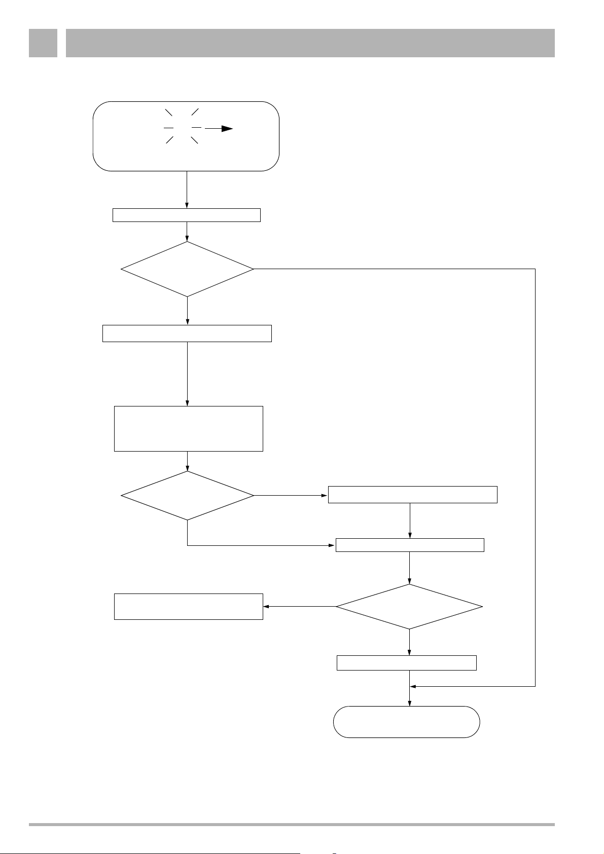
Page 11
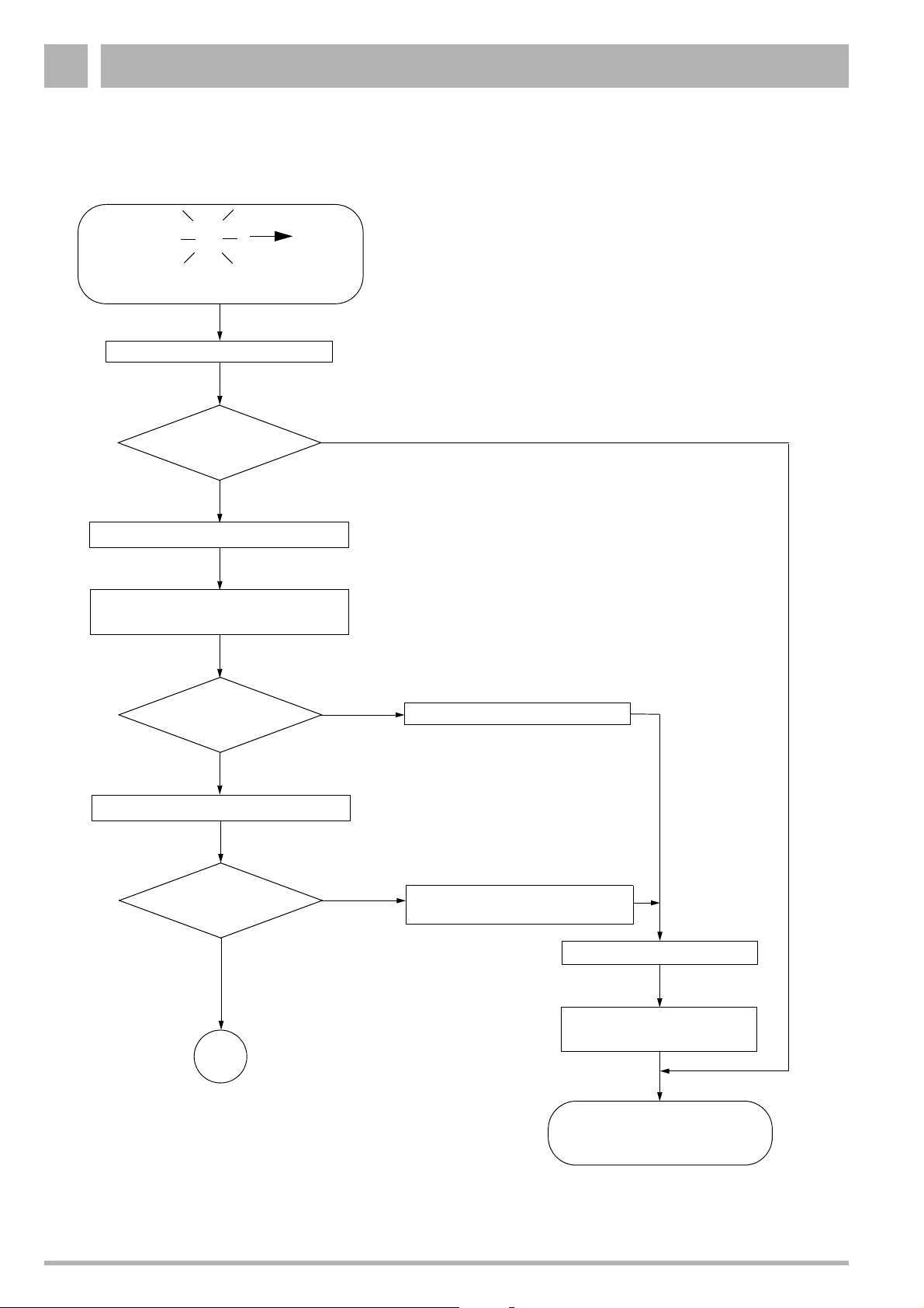
Troubleshooting 3
2
Excessive temperature
increase at safety sensor
Wait approx. 30 sec for the boiler to return
automatically to normal operation
New fault warning message
Check system and heat exchanger, as
indicated in the installation and servicing
instructions, for signs of airlocks and dirt -
purge and/or clean as required
Are all
maintenance shutoff
valves open?
Is the water
pressure in the system at
least 1 bar?
P
2P?
Yes
Yes
No
No
No
Open maintenance shutoff valves
Fill up with water as indicated in the
installation and servicing instruc-
tions, and purge the system of air
Yes
Is at least one
thermostatic valve open (to
control the amount of water
circulating)?
Yes
Remove the casing (page 48)
Check safety sensor and wiring
(page 55)
Safety sensor OK?
Yes
Check circulation pump (page 54)
Circulation pump OK?
Yes
Filter to catch dirt fitted?
If yes, is it unclogged?
No
No
No
Open one thermostatic valve
Replace safety sensor
(page 55)
Replace circulation pump (page 54)
Fit the casing (page 48)
"reset"
A
page 46
Fig. 8 Fault warning message 2P: Excessive temperature increase at safety sensor
Subject to modifications resulting from technical improvements! Buderus Ltd. • http://www.buderus-domestic.co.uk
Servicing manual for wall-mounted condensing gas boiler 600 Series 11S/19S/24S/24C • Issued 02/2006 11
600 Series 11S / 19S / 24S / 24C
OK
Page 12
Troubleshooting3
Flashing
3
C
Bad plug-in connection at cable loom,
or damaged wiring
"reset"
New fault warning
message 3C?
Yes
Remove the casing (page 48)
Check for a damaged or broken
connection lead between plugs
03-20 and 04-20 of the 20-core
lead to the UBA
No
Wiring OK?
Yes
Use the corresponding flow diagram
to diagnose and deal with the fault.
No
Replace cable
"reset"
Yes
600 Series 11S / 19S / 24S / 24C
New fault warning
message?
No
Fit the casing (page 48)
OK
Fig. 9 Fault warning message 3C: Bad plug-in connection at cable loom, or damaged wiring
Subject to modifications resulting from technical improvements! Buderus Ltd. • http://www.buderus-domestic.co.uk
12 Servicing manual for wall-mounted condensing gas boiler 600 Series 11S/19S/24S/24C • Issued 02/2006
Page 13
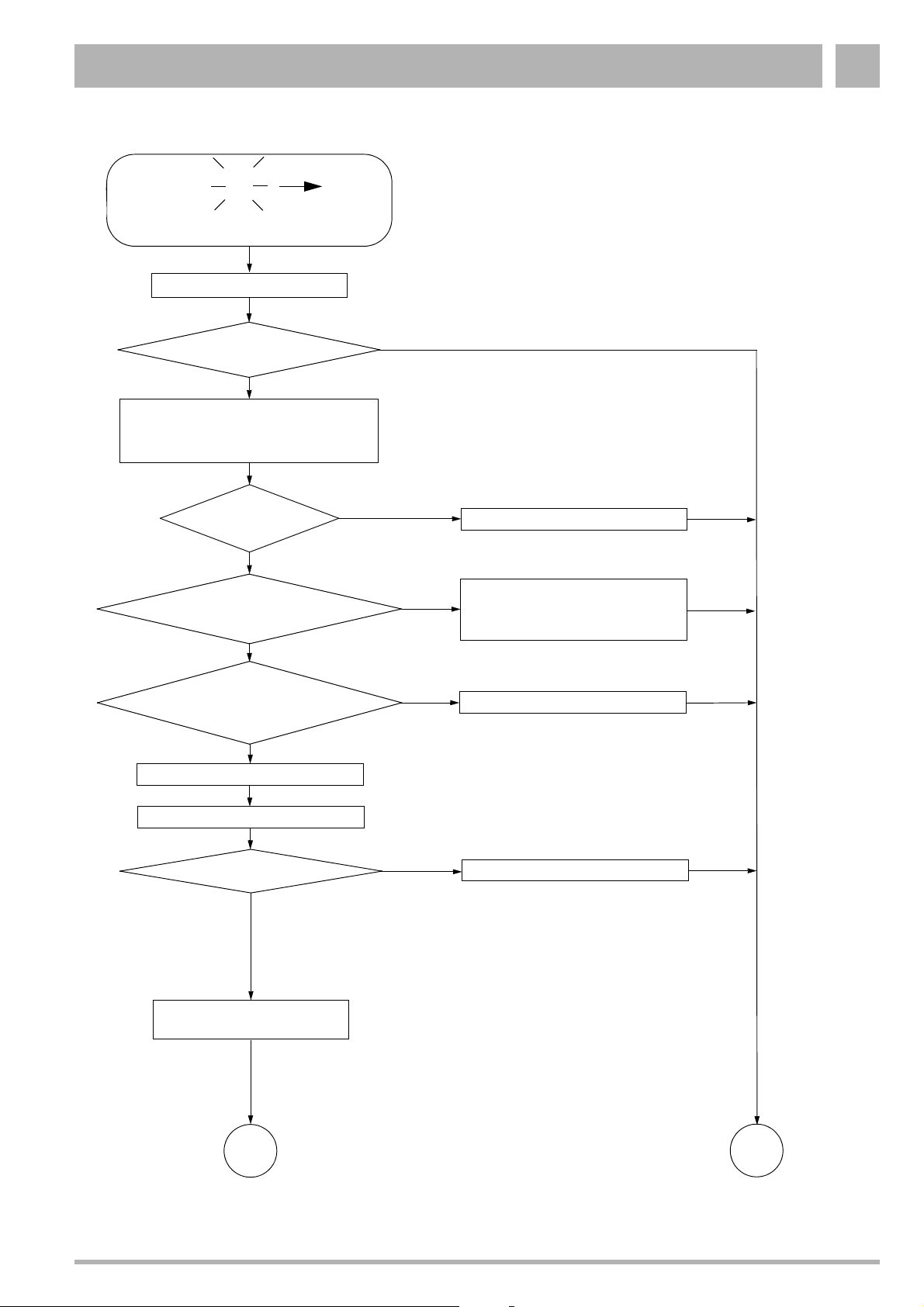
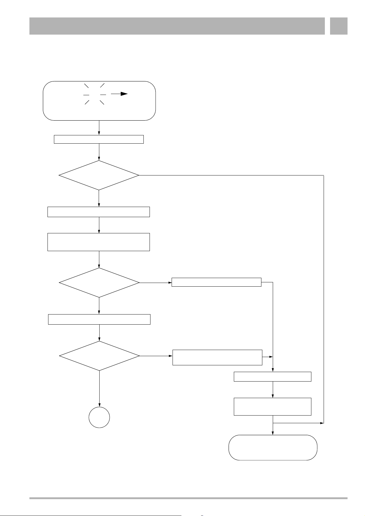
Troubleshooting 3
Flashing
4
Feed sensor above 100 °C
"reset"
New fault warning message
4A?
Yes
Check system and heat exchanger, as
indicated in the installation and servicing
instructions, for signs of airlocks and
dirt - purge and/or clean as required.
Are all
maintenance shutoff
valves open?
Yes
Is the water
pressure in the system at
least 1 bar?
Yes
A
No
No
No
Open maintenance shutoff valves
Fill up with water as indicated in the
installation and servicing instruc-
tions, and purge the system of air
Is at least one
thermostatic valve open (to control
the amount of water cir-
culating)?
Yes
Remove the casing (page 48)
Check circulation pump (page 54)
Circulation pump OK?
Yes
Filter to catch dirt fitted?
If yes, is it unclogged?
No
No
Open one thermostatic valve
Replace circulation pump (page 54)
16
page 14
Fig. 10 Fault warning message 4A: Feed sensor above 100 °C
Subject to modifications resulting from technical improvements! Buderus Ltd. • http://www.buderus-domestic.co.uk
Servicing manual for wall-mounted condensing gas boiler 600 Series 11S/19S/24S/24C • Issued 02/2006 13
17
page 14
Page 14
Troubleshooting3
page 13
16
Check feed sensor and feed-sensor
connection wiring (page 56)
Flow sensor
and wiring
OK?
Yes
A
No
page 13
17
Replace feed sensor or cable
(page 56)
"reset"
page 46
Fit the casing (page 48)
600 Series
11S / 19S / 24S / 24C
OK
Fig. 11 Continuation of fault warning message 4A: Feed sensor above 100 °C
Subject to modifications resulting from technical improvements! Buderus Ltd. • http://www.buderus-domestic.co.uk
14 Servicing manual for wall-mounted condensing gas boiler 600 Series 11S/19S/24S/24C • Issued 02/2006
Page 15
Troubleshooting 3
Flashing
4
F2 fuse malfunction, or exhaust-gas
sensor tripped
"reset"
New fault
warning message
4C?
Yes
Remove the casing (page 48)
Check miniature fuse F2 (page 53)
Miniature fuse F2 OK?
C
No
No
Fuse (1.25 AT) should be
replaced
Yes
Check wiring connection of UBA
(page 53)
Wiring connection
OK?
Yes
Check exhaust-gas sensor
(page 49)
Exhaust-gas
sensor OK?
Yes
18
No
No
Connect lead correctly
Replace exhaust-gas sensor
(page 49)
19
20
page 16
Fig. 12 Fault warning message 4C: F2 fuse malfunction, or exhaust-gas sensor tripped
Subject to modifications resulting from technical improvements! Buderus Ltd. • http://www.buderus-domestic.co.uk
Servicing manual for wall-mounted condensing gas boiler 600 Series 11S/19S/24S/24C • Issued 02/2006 15
page 16
page 16
Page 16
Troubleshooting3
page 15
18
Open the heat exchanger and
burner, as indicated in the installation
and servicing instructions, and check
for dirt
Are the heat exchang-
er and burner soiled?
No
Shut the heat exchanger and burner
Yes
Clean the heat exchanger
and burner, as indicated in
the installation and servicing
instructions
page 15
19
"reset"
page 15
20
A
page 46
Fit the casing
(page 48)
600 Series
11S / 19S / 24S / 24C
OK
Fig. 13 Continuation of fault warning message 4C: F2 fuse malfunction, or exhaust-gas sensor tripped
Subject to modifications resulting from technical improvements! Buderus Ltd. • http://www.buderus-domestic.co.uk
16 Servicing manual for wall-mounted condensing gas boiler 600 Series 11S/19S/24S/24C • Issued 02/2006
Page 17
Troubleshooting 3
Flashing
4
Safety sensor temp. exceeds 100 °C
"reset"
New fault
warning message 4F?
Yes
Check system and heat exchanger, as
indicated in the installation and servicing
instructions, for signs of airlocks and
dirt - purge and/or clean as required
Are all
maintenance shutoff
valves open?
Yes
Is the water
pressure in the system at
least 1 bar?
F
No
No
No
Open maintenance shutoff valves
Fill up with water as indicated in the
installation and servicing instruc-
tions, and purge the system of air
Yes
Is at least one
thermostatic valve open (to
control the amount of water
circulating)?
Yes
Remove the casing (page 48)
Check circulation pump (page 54)
Circulation pump OK?
Yes
Check safety sensor
(page 55)
Safety sensor
OK?
Yes
No
No
No
Open one thermostatic valve
Replace circulation pump (page 54)
Replace safety sensor
(page 55)
Fit the casing (page 48)
"reset"
A
600 Series 11S / 19S / 24S / 24C
page 46
Fig. 14 Fault warning message 4F: Safety sensor temp. exceeds 100 °C
Subject to modifications resulting from technical improvements! Buderus Ltd. • http://www.buderus-domestic.co.uk
Servicing manual for wall-mounted condensing gas boiler 600 Series 11S/19S/24S/24C • Issued 02/2006 17
OK
Page 18
Troubleshooting3
Flashing
4
Dripping tap
There is constant heat monitoring
over a period of 4 hours, but the
boiler has been heating up for less
than 20 minutes. The hot water
requirement is now blocked for one
hour, or the restriction lifted if a heat
requirement arises.
Is there a
dripping tap somewhere in
the hot-water system?
Yes
H
No
Please deal with this item
Yes
"reset"
New fault warning
message 4H?
No
600 Series
11S / 19S / 24S / 24C
OK
Fig. 15 Fault warning message 4H: Dripping tap
Subject to modifications resulting from technical improvements! Buderus Ltd. • http://www.buderus-domestic.co.uk
18 Servicing manual for wall-mounted condensing gas boiler 600 Series 11S/19S/24S/24C • Issued 02/2006
Page 19
Troubleshooting 3
Flashing
4
Short circuit at safety sensor
"reset"
New fault warning
message 4L?
Yes
Remove the casing (page 48)
Check wiring to safety sensor for short
circuits (page 55)
L
No
Wiring OK?
Yes
Check safety sensor (page 55)
Safety sensor
OK?
Yes
A
page 46
No
No
Replace cable
Replace safety sensor
(page 55)
"reset"
Fit the casing
(page 48)
600 Series
11S / 19S / 24S / 24C
OK
Fig. 16 Fault warning message 4L: Short circuit in safety sensor
Subject to modifications resulting from technical improvements! Buderus Ltd. • http://www.buderus-domestic.co.uk
Servicing manual for wall-mounted condensing gas boiler 600 Series 11S/19S/24S/24C • Issued 02/2006 19
Page 20
Troubleshooting3
Flashing
4
Safety sensor, loose contact
or defect
"reset"
New fault warning
message 4P?
Yes
Remove the casing (page 48)
Check wiring to safety sensor for loose
contacts (page 55)
P
No
Wiring OK?
Yes
Check safety sensor (page 55)
Safety sensor
OK?
Yes
A
page 46
No
No
Replace cable (page 55)
Replace safety sensor (page 55)
"reset"
Fit the casing
(page 48)
600 Series
11S / 19S / 24S / 24C
OK
Fig. 17 Fault warning message 4P: Safety sensor, loose contact or defect
Subject to modifications resulting from technical improvements! Buderus Ltd. • http://www.buderus-domestic.co.uk
20 Servicing manual for wall-mounted condensing gas boiler 600 Series 11S/19S/24S/24C • Issued 02/2006
Page 21
Troubleshooting 3
Flashing
4
Short circuit in feed sensor
"reset"
New fault warning
message 4U?
Yes
Remove the casing (page 48)
Check wiring to feed sensor for short
circuits (page 56)
U
No
Wiring OK?
Yes
Check feed sensor (page 56)
Feed sensor
OK?
Yes
A
page 46
No
No
Replace cable
Replace feed sensor
(page 56)
"reset"
Fit the casing
(page 48)
600 Series
11S / 19S / 24S / 24C
OK
Fig. 18 Fault warning message 4U: Short circuit in feed sensor
Subject to modifications resulting from technical improvements! Buderus Ltd. • http://www.buderus-domestic.co.uk
Servicing manual for wall-mounted condensing gas boiler 600 Series 11S/19S/24S/24C • Issued 02/2006 21
Page 22

Troubleshooting3
Flashing
4
Feed sensor, loose contact or
defective
"reset"
New fault warning
message 4Y?
Yes
Remove the casing (page 48)
Check wiring to feed sensor for loose
contacts (page 56)
Y
No
Wiring OK?
Yes
Check feed sensor (page 56)
Flow sensor
OK?
Yes
A
page 46
No
No
Replace cable
Replace feed sensor
(page 56)
"reset"
Fit the casing
(page 48)
600 Series
11S / 19S / 24S / 24C
OK
Fig. 19 Fault warning message 4Y: Feed sensor, loose contact or defective
Subject to modifications resulting from technical improvements! Buderus Ltd. • http://www.buderus-domestic.co.uk
22 Servicing manual for wall-mounted condensing gas boiler 600 Series 11S/19S/24S/24C • Issued 02/2006
Page 23

Troubleshooting 3
Flashing
5
600 Serie has switched off
after connection of diagnosis plug
"reset"
600 Series
11S / 19S / 24S / 24C
OK
C
Fig. 20 Fault warning message 5C: 600 Series has switched off after disconnection of diagnosis plug
Subject to modifications resulting from technical improvements! Buderus Ltd. • http://www.buderus-domestic.co.uk
Servicing manual for wall-mounted condensing gas boiler 600 Series 11S/19S/24S/24C • Issued 02/2006 23
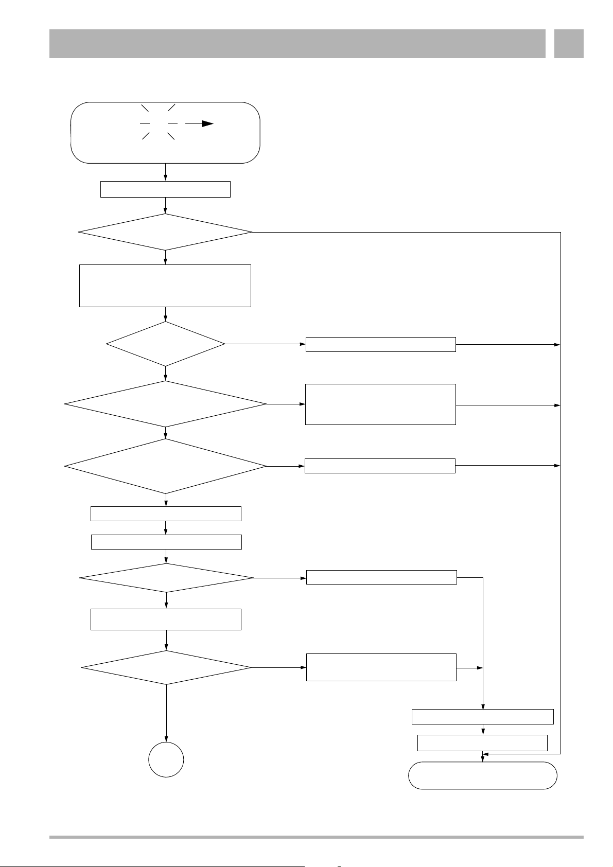
Page 24

Troubleshooting3
Flashing
6
F1 fuse defective, or no ionisation
message after ignition
"reset"
Is the gas-supply shutoff
valve open?
Yes
Remove the casing (page 48)
Did the incandes-
cent firing electrode glow
during ignition?
Yes
Did the gas valve
open during ignition? (Noise
from switch)
A
No
No
No
Open gas-supply shutoff valve
21
22
page 25
page 26
Yes
Is the fan running?
Yes
Measure connection pressure (18 - 25 mbar),
as indicated in installation and servicing
instructions
Gas connection pressure
OK?
Yes
Carry out the following tasks as shown in the
Installation and Servicing Instructions: Check
exhaust-gas system (operation independent of
room-air), Check gas-air ratio of supply
Gas-air ratio OK?
Yes
No
No
No
23
Contact local gas-supply
Adjust gas/air ratio as indicated in the
installation and servicing instructions
page 27
utility
"reset"
Fit the casing (page 48)
24
page 25
Fig. 21 Fault warning message 6A: F1 fuse defective, or no ionisation message after ignition
Subject to modifications resulting from technical improvements! Buderus Ltd. • http://www.buderus-domestic.co.uk
24 Servicing manual for wall-mounted condensing gas boiler 600 Series 11S/19S/24S/24C • Issued 02/2006
600 Series 11S / 19S / 24S / 24C
OK
Page 25

Troubleshooting 3
page 24
21
Check fuse F1 (page 53)
Fuse OK?
No
Fuse (1.25 AT) should be
replaced
Yes
Replace hot surface ingitor
(page 59)
A
page 46
Check hot surface ingitorhot surface
ingitor (page 59)
No
Measure ionisation current
Yes
Replace ionization electrode
hot surface
ingitor OK?
Yes
(page 63)
Ionization
electrode OK?
No
(page 63)
24
page 24
Has fuse
been replaced twice in
quick succession?
Yes
No
"reset"
Fit the casing
(page 48)
A
page 46
600 Series
11S / 19S / 24S / 24C
OK
Fig. 22 Continuation of fault warning message 6A: F1 fuse defective, or no ionisation message after ignition
Subject to modifications resulting from technical improvements! Buderus Ltd. • http://www.buderus-domestic.co.uk
Servicing manual for wall-mounted condensing gas boiler 600 Series 11S/19S/24S/24C • Issued 02/2006 25
Page 26

Troubleshooting3
page 24
22
Check switching contact of floor
thermostat (page 53)
Switch contact
OK?
Yes
Check lead connections on gas
burner subassembly
Wiring connec-
tions OK?
Yes
Check gas-burner subassembly for
correct activation (page 60)
No
No
Connect switch contact
correctly
Connect wiring correctly
Activation
OK?
No
Yes
A
page 46
Fig. 23 Continuation of fault warning message 6A: F1 fuse defective, or no ionisation message after ignition
Subject to modifications resulting from technical improvements! Buderus Ltd. • http://www.buderus-domestic.co.uk
Replace gas-burner assembly
(page 60)
"reset"
Fit the casing
(page 48)
600 Series
11S / 19S / 24S / 24C
OK
26 Servicing manual for wall-mounted condensing gas boiler 600 Series 11S/19S/24S/24C • Issued 02/2006
Page 27

Troubleshooting 3
page 24
23
Check that the fan-unit connection
plug is correctly inserted
Plug OK?
Yes
Replace fan unit
(page 51)
"reset"
Fit the casing
(page 48)
600 Series
11S / 19S / 24S / 24C
OK
No
Insert plug correctly
Fig. 24 Continuation of fault warning message 6A: F1 fuse defective, or no ionisation message after ignition
Subject to modifications resulting from technical improvements! Buderus Ltd. • http://www.buderus-domestic.co.uk
Servicing manual for wall-mounted condensing gas boiler 600 Series 11S/19S/24S/24C • Issued 02/2006 27
Page 28

Troubleshooting3
6
Ionisation message,
but no flame
Remove the casing (page 48)
Check gas burner subassembly
(page 60)
Gas burner
assembly activates without
instructions having been issued to
the effect (Display
UBA
C
0H)
Yes
A
No
Replace ionization electrode
(page 63)
"reset"
page 46
Fit the casing
(page 48)
600 Series
11S / 19S / 24S / 24C
OK
Fig. 25 Fault warning message 6C: Ionisation message, but no flame
Subject to modifications resulting from technical improvements! Buderus Ltd. • http://www.buderus-domestic.co.uk
28 Servicing manual for wall-mounted condensing gas boiler 600 Series 11S/19S/24S/24C • Issued 02/2006
Page 29

Troubleshooting 3
6 H
Flame dies out after main gas
valve is opened
"reset"
Is the gas-supply shutoff valve
completely open?
Yes
Remove the casing (page 48)
Measure the gas connection
pressure
Put system into chimney sweeper mode
(page 47)
Are the minimum-
pressure specifications being
observed (17 mbar min. for
natural gas)?
Yes
No
No
If the required connection
pressure is not available, con-
tact your gas utility company
Open gas valve
completely
"reset"
Fit the casing
(page 48)
Check gas/air ratio as indicated in
the installation and servicing
instructions
Gas-air ratio
OK?
Yes
Check gas-air injector for correct
fitting; check for correct diameter
Fig. 26 Fault warning message 6H: Flame dies out after main gas valve is opened
Subject to modifications resulting from technical improvements! Buderus Ltd. • http://www.buderus-domestic.co.uk
Servicing manual for wall-mounted condensing gas boiler 600 Series 11S/19S/24S/24C • Issued 02/2006 29
No
Adjust gas/air ratio as indi-
cated in the installation and
servicing instructions
600 Series
11S / 19S / 24S / 24C
OK
Page 30

Troubleshooting3
6 L
Flame goes out during warm-up
phase
"reset"
Is the gas-supply shutoff
valve completely open?
Yes
Remove the casing (page 48)
Measure the gas connection
pressure
Put system into chimney sweep mode
(page 47)
Are the minimum-
pressure specifications being
observed (17 mbar min. for
natural gas)?
Yes
No
No
If the required connection
pressure is not available,
contact your gas utility
company
Open gas valve
completely
"reset"
Fit the casing
(page 48)
Check gas/air ratio as indicated in the
installation and servicing instructions
Gas-air ratio
OK?
Yes
Check gas-air injector for correct fitting
and possible clogging; check for correct
diameter
Fig. 27 Fault warning message 6L: Flame goes out during warm-up phase
Subject to modifications resulting from technical improvements! Buderus Ltd. • http://www.buderus-domestic.co.uk
30 Servicing manual for wall-mounted condensing gas boiler 600 Series 11S/19S/24S/24C • Issued 02/2006
No
Adjust gas/air ratio as
indicated in the installation
and servicing instructions
600 Series
11S / 19S / 24S / 24C
OK
Page 31

Troubleshooting 3
Flashing
7
Voltage in UBA too low/high
"reset"
A
Yes,
on second and
third attempts
to start up
New fault warning
message 7A?
Yes, on fourth attempt to start up
Check Mains voltage
(195 V to 253 V)
Mains voltage
OK?
Yes
Remove the casing (page 48)
No
No
Contact local energy-supply
utility
Is regulator connected to
incorrect terminals?
Yes
Connect correctly
Fig. 28 Fault warning message 7A: Voltage in UBA too low or too high
Subject to modifications resulting from technical improvements! Buderus Ltd. • http://www.buderus-domestic.co.uk
Servicing manual for wall-mounted condensing gas boiler 600 Series 11S/19S/24S/24C • Issued 02/2006 31
No
A
page 46
600 Series
11S / 19S / 24S / 24C
OK
Page 32

Troubleshooting3
Flashing
7
Mains voltage interrupted following a
fault warning message
Keep "reset" button pressed for at
least 5 sec.
Use the corresponding flow diagram
to diagnose and deal with the
original fault
C
Fig. 29 Fault warning message 7C: Mains voltage interrupted following a fault warning message
Subject to modifications resulting from technical improvements! Buderus Ltd. • http://www.buderus-domestic.co.uk
32 Servicing manual for wall-mounted condensing gas boiler 600 Series 11S/19S/24S/24C • Issued 02/2006
Page 33

Troubleshooting 3
Flashing
7
F3 fuse defect, or UBA system error
Remove the casing (page 48)
Check miniature fuse F3 (page 53)
F
Is F3 defective?
No
A
page 46
Yes
Fuse (1.25 AT) should be
replaced
Has fuse been replaced
twice in quick succession?
Yes
Check electrical control system of
three-way valve (page 64)
Operation
OK?
Yes
Replace three-way valve
(page 65)
No
No
A
page 46
"reset"
Fit the casing (page 48)
600 Series
11S / 19S / 24S / 24C
OK
Fig. 30 Fault warning message: 7F: F3 fuse defect, or UBA system error
Subject to modifications resulting from technical improvements! Buderus Ltd. • http://www.buderus-domestic.co.uk
Servicing manual for wall-mounted condensing gas boiler 600 Series 11S/19S/24S/24C • Issued 02/2006 33
Page 34

Troubleshooting3
Flashing
7
Voltage peaks in UBA
"reset"
H
Yes,
on second and
third attempts
to start up
New fault warning
message 7H?
Yes, on fourth attempt to start up
Check Mains voltage
(195 V to 253 V)
Mains voltage
OK?
Yes
Remove the casing (page 48)
No
No
Contact electricity supplier
and Buderus
Customer Service
A
page 46
600 Series
11S / 19S / 24S / 24C
Fig. 31 Fault warning message 7H: Voltage peaks in UBA
Subject to modifications resulting from technical improvements! Buderus Ltd. • http://www.buderus-domestic.co.uk
34 Servicing manual for wall-mounted condensing gas boiler 600 Series 11S/19S/24S/24C • Issued 02/2006
OK
Page 35

Troubleshooting 3
Flashing
7
UBA timer error
"reset"
L
New fault warning
message 7L?
Yes
Remove the casing (page 48)
A
page 46
No
600 Series
11S / 19S / 24S / 24C
OK
Fig. 32 Fault warning message 7L: UBA timer error
Subject to modifications resulting from technical improvements! Buderus Ltd. • http://www.buderus-domestic.co.uk
Servicing manual for wall-mounted condensing gas boiler 600 Series 11S/19S/24S/24C • Issued 02/2006 35
Page 36

Troubleshooting3
Flashing
8
External switching contact,
e.g. temperature monitor for floor
heating, has been tripped
Y
Switch
contact OK?
No
Replace switch contact
Yes
Yes
Remove the casing (page 48)
Is there
an external switching
contact?
Contacts in cable
loom OK?
Yes
No
No
Connect contacts correctly
"reset"
New fault warning
message 8Y?
Yes
No
Fit the casing
(page 48)
600 Series
A
page 46
Fig. 33 Fault warning message 8Y: External switching contact, e.g. temperature monitor for floor heating, has been tripped
Subject to modifications resulting from technical improvements! Buderus Ltd. • http://www.buderus-domestic.co.uk
36 Servicing manual for wall-mounted condensing gas boiler 600 Series 11S/19S/24S/24C • Issued 02/2006
11S / 19S / 24S / 24C
OK
Page 37

Troubleshooting 3
Any charac-
9
A
E
ter, except
P
Yes, on second or
third attempt to
start up
System error
"reset"
New fault warning
message 9A?
No
Other fault
warning message?
Yes
System error
Yes,
on fourth
attempt to
start up
Use the corresponding flow diagram
to diagnose and deal with the fault
B
page 46
600 Series
11S / 19S / 24S / 24C
OK
Fig. 34 Fault warning message 9A (with any character except P): System error
Subject to modifications resulting from technical improvements! Buderus Ltd. • http://www.buderus-domestic.co.uk
Servicing manual for wall-mounted condensing gas boiler 600 Series 11S/19S/24S/24C • Issued 02/2006 37
Page 38

Troubleshooting3
Flashing
9
Incorrect cable connection at UBA,
or KIM defective
Remove the casing (page 48)
Check cable connections at
KIM
Check wiring connection in UBA
(page 53)
C
Connections OK?
Yes
A
page 46
No
Connect all terminals
correctly
"reset", Fit the casing
600 Series
11S / 19S / 24S / 24C
OK
Fig. 35 Fault warning message 9C: Wiring to KIM connected incorrectly
Subject to modifications resulting from technical improvements! Buderus Ltd. • http://www.buderus-domestic.co.uk
38 Servicing manual for wall-mounted condensing gas boiler 600 Series 11S/19S/24S/24C • Issued 02/2006
Page 39

Troubleshooting 3
Flashing
9
Timer error (UBA defective)
F,H,P
At second
attempt
At third
attempt
B
page 46
Yes
"reset"
New fault warning
message 9P?
No
New fault warning
message 9F or 9H?
No
Yes
B
page 46
Use the corresponding flow diagram
to diagnose and deal with the fault
"reset"
Yes
New fault warning
message 9P?
No
600 Series
11S / 19S / 24S / 24C
Fig. 36 Fault warning message 9F,H,P: System error (UBA defective), or KIM defective
Subject to modifications resulting from technical improvements! Buderus Ltd. • http://www.buderus-domestic.co.uk
Servicing manual for wall-mounted condensing gas boiler 600 Series 11S/19S/24S/24C • Issued 02/2006 39
OK
Page 40

Troubleshooting3
Flashing
9
Wiring to gas-valve assembly incorrect,
or loose wiring connections in UBA
Remove the casing (page 48)
Check connection lead to gas burner
assembly
Check wiring connection in UBA
(page 53)
L
Connections OK?
Yes
A
page 46
No
Connect all terminals correctly
"reset"
Fit the casing
(page 48)
600 Series
11S / 19S / 24S / 24C
Fig. 37 Fault warning message 9L: Wiring to gas-valve assembly incorrect, or loose wiring connections in UBA.
Subject to modifications resulting from technical improvements! Buderus Ltd. • http://www.buderus-domestic.co.uk
40 Servicing manual for wall-mounted condensing gas boiler 600 Series 11S/19S/24S/24C • Issued 02/2006
OK
Page 41

Troubleshooting 3
Flashing
9
Wiring to gas-valve assembly incorrect,
or loose wiring connections in UBA
Remove the casing (page 48)
U
Set the mains switch to "0".
Check wiring connection in UBA
(page 53)
Connections OK?
No
Connect all terminals correctly
Set the mains switch to "1".
Yes
Yes
page 46
A
KIM connected
correctly?
"reset"
No
"reset"
"reset"
Set the mains switch to "1".
New fault warning
message 9U?
No
Yes
Use the corresponding flow diagram
to diagnose and deal with the
fault
Fig. 38 Fault warning message 9U: Incorrect cable connection at UBA (KIM defective)
Subject to modifications resulting from technical improvements! Buderus Ltd. • http://www.buderus-domestic.co.uk
Servicing manual for wall-mounted condensing gas boiler 600 Series 11S/19S/24S/24C • Issued 02/2006 41
Other fault warning
message ?
No
Fit the casing
(page 48)
600 Series
11S / 19S / 24S / 24C
OK
Yes
Contact Buderus
Customer Service
Fit the casing
(page 48)
Page 42

Troubleshooting3
E P
Non-compatible UBA installed
UBA software
version 3.5
or better?
No
Install version 3.5 (or better) of
UBA software
Fit the casing
(page 48)
"reset"
600 Series
11S / 19S / 24S / 24C
OK
Yes
A
page 46
Fig. 39 Fault warning message EP: Non-compatible UBA installed
Subject to modifications resulting from technical improvements! Buderus Ltd. • http://www.buderus-domestic.co.uk
42 Servicing manual for wall-mounted condensing gas boiler 600 Series 11S/19S/24S/24C • Issued 02/2006
Page 43

Troubleshooting 3
No mains water, despite system being
ready for operation
Is the chimney
sweep switch set
to "0"?
Yes
Remove the casing (page 48)
Check three-way valve for correct
activation (page 64) ?
Activation
OK?
Yes
Check three-way valve
No
No
Set the chimney-sweep switch
to "0"
600 Series
11S / 19S / 24S / 24C
OK
A
page 46
Three-way valve
OK?
Yes
26
page 44
Fig. 40 Malfunction: No mains water, despite system being ready for operation
Subject to modifications resulting from technical improvements! Buderus Ltd. • http://www.buderus-domestic.co.uk
No
Replace three-way valve (page 65)
27
page 44
Servicing manual for wall-mounted condensing gas boiler 600 Series 11S/19S/24S/24C • Issued 02/2006 43
Page 44

Troubleshooting3
page 43
27
Check mains-water sensor (page 57)
Mains-water
sensor OK?
Yes
A
page 46
No
Replace mains-water sensor
(page 58)
26
page 43
Fit the casing
(page 48)
600 Series
11S / 19S / 24S / 24C
OK
Fig. 41 Continued malfunction: No mains water, despite system being ready for operation
Subject to modifications resulting from technical improvements! Buderus Ltd. • http://www.buderus-domestic.co.uk
44 Servicing manual for wall-mounted condensing gas boiler 600 Series 11S/19S/24S/24C • Issued 02/2006
Page 45

Troubleshooting 3
No heating operation, despite request for
activation and display message indicating that
system is ready for use
Check control-unit configuration and
wiring connections to unit
Configuration OK?
Yes
Remove the casing
(page 48)
Check control-unit connection to UBA
(page 66)
Connections in
UBA OK?
Yes
Connections at the
ERC/RC OK?
No
No
Adjust settings and press "reset"
Configure connections correctly
Fit the casing
(page 48)
600 Series
Replace lead or control unit
Still no heating
operation?
11S / 19S / 24S / 24C
OK
A
page 46
Fig. 42 Malfunction: No heating operation, despite request for activation and display message indicating that system is ready for use
Subject to modifications resulting from technical improvements! Buderus Ltd. • http://www.buderus-domestic.co.uk
Servicing manual for wall-mounted condensing gas boiler 600 Series 11S/19S/24S/24C • Issued 02/2006 45
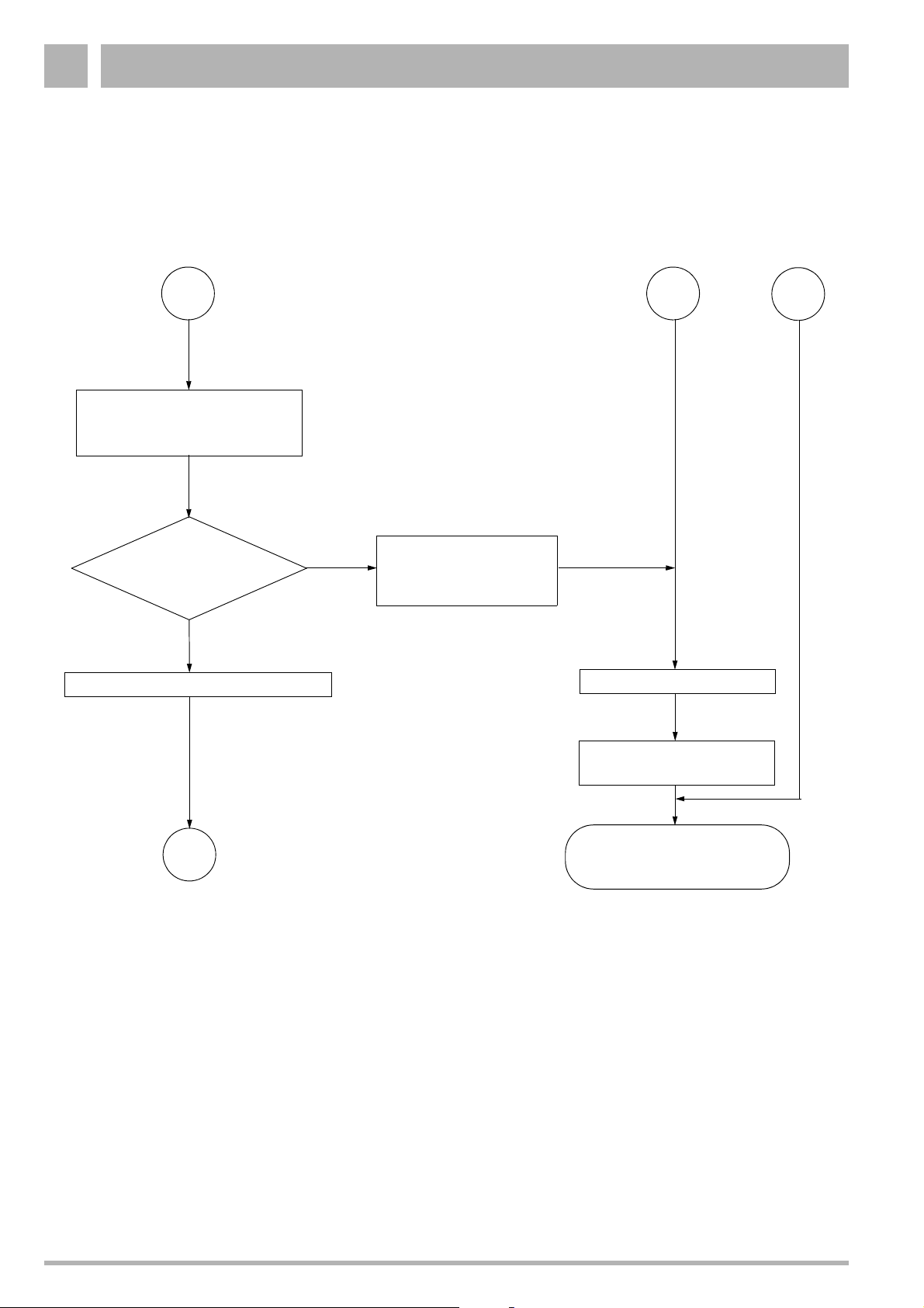
Page 46

Troubleshooting3
A
Check all plug-in connections on UBA and
all plug-in connections in general
B
Connection plug
and plug-in con-
nections OK?
Yes
Replace UBA (page 50) or contact
Buderus Customer Service
Use the corresponding flow diagram
to diagnose and correct the fault
No
Correct contact malfunction
"reset"
Yes
New fault warning
message?
Fit the casing
(page 48)
No
600 Series
11S / 19S / 24S / 24C
OK
Fig. 43 Continued malfunction: No heating operation, despite request for activation and display message indicating that system is ready for use
Subject to modifications resulting from technical improvements! Buderus Ltd. • http://www.buderus-domestic.co.uk
46 Servicing manual for wall-mounted condensing gas boiler 600 Series 11S/19S/24S/24C • Issued 02/2006
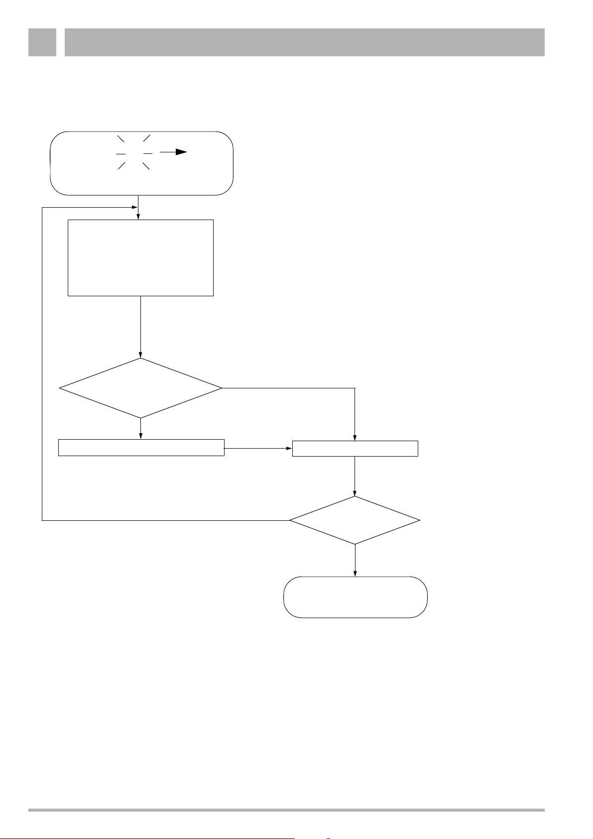
Page 47

Troubleshooting 3
12
10
01
11
KW
10
1
1
1
3.1 Troubleshooting tasks
CAUTION
All work on the gas supply must be carried out
by a CORGI registered engineer.
All work on water and electrical supplies must
be carried out by a competent person.
3.1.1 Unblocking the 600 Series 11S / 19S / 24S / 24C
Press the “reset” button (fig. 44) after rectifying each fault.
A letter “r” will appear on the display.
This unblocks the UBA and returns it to standby mode.
NOTE
The system cannot be unblocked by
disconnecting at the master switch.
If the "reset" button is not kept pressed for long enough, the
display will first show a "7" and, after the Service button is
pressed, a "C".
Unblock by pressing the “reset” button once more and keeping
it pressed for the required time.
Fig. 44 "Reset" button
3.1.2 Chimney-sweep mode
Certain troubleshooting tasks must be carried out with the
600 Series 11S / 19S / 24S / 24C in heating mode.
z Before proceeding, open the cover of the second operating
level on the UBA (fig. 45).
z Set the chimney-sweep switch to “1”.
z Remember to return the chimney-sweep switch to “0” once
work is complete.
z Close the cover of the second operating level on the UBA.
NOTE
The system cannot be used to supply hot water
while it is in chimney-sweep mode. With
chimney sweep mode activated, the boiler
heats up to its preset feed temperature.
01
Fig. 45 Chimney-sweep switch
Subject to modifications resulting from technical improvements! Buderus Ltd. • http://www.buderus-domestic.co.uk
Servicing manual for wall-mounted condensing gas boiler 600 Series 11S/19S/24S/24C • Issued 02/2006 47
Page 48

Troubleshooting3
3.1.3 Removing and refitting the outer casing
z Note current display.
z Set the mains switch to “0”.
z Loosen the fixing screw (fig. 46, item 1).
z Detach the outer casing.
z To refit the casing, follow the above procedure in reverse
order. Then return the mains switch to “I”.
3.1.4 Removing and refitting the combustion-chamber cover
1
Fig. 46 Remove outer casing
z Open the clip fastenings (fig. 47, item 1).
z Remove combustion-chamber cover.
z To refit the cover, follow the above procedure in reverse
order.
1
1
Fig. 47 600 Series 11S / 19S / 24S / 24C:
Remove combustion-chamber cover
Fig. 48 600 Series 24C: Combi-unit
Subject to modifications resulting from technical improvements! Buderus Ltd. • http://www.buderus-domestic.co.uk
48 Servicing manual for wall-mounted condensing gas boiler 600 Series 11S/19S/24S/24C • Issued 02/2006
Page 49

Troubleshooting 3
3.1.5 Checking the exhaust-gas sensor
z Detach plug-and-socket connection on cable to exhaust-
gas sensor. Ensure that no cable is earthed (grounded) at
any point.
z Allow the exhaust-gas sensor to cool down.
Activation temperature:
600 Series 11S / 19S / 24S / 24C: 105 °C
z Check exhaust-gas sensor for free throughput. If
throughput is not free, the exhaust-gas sensor is defective.
z Replace any exhaust-gas sensor found to be defective.
Ensure you use only genuine Buderus spare parts.
z If the exhaust-gas sensor is working correctly, plug it in
once more.
Fig. 49 600 Series 11S / 19S / 24S / 24C:
Checking the exhaust-gas sensor
3.1.6 Replacing the exhaust-gas sensor
z Unscrew the flow-backup mounting.
z Detach the cable plug at the exhaust-gas sensor.
z Loosen both retaining screws on the exhaust-gas sensor.
z Remove the exhaust-gas sensor and replace with a new
unit (fig. 50).
z Retighten the retaining screws.
z Reconnect the cable plug.
z Screw the mounting into place.
Fig. 50 600 Series 11S / 19S / 24S / 24C:
Replacing the exhaust-gas sensor
Subject to modifications resulting from technical improvements! Buderus Ltd. • http://www.buderus-domestic.co.uk
Servicing manual for wall-mounted condensing gas boiler 600 Series 11S/19S/24S/24C • Issued 02/2006 49
Page 50

Troubleshooting3
3.1.7 Checking the air intake and outlet openings
z Check to ensure that the air intake and outlet openings are
of sufficient size, and that they are not obstructed or
clogged.
3.1.8 Replacing the UBA
z Disconnect the system from the power supply.
z Loosen crosshead screw (fig. 51, item 1) on UBA housing.
z Swivel UBA housing downwards.
1
z Open the UBA housing (fig. 52).
z Note the position of the cable plugs, disconnect all cable
plugs.
z Open the mains connection box by loosening the screw.
z Loosen the four screws and remove the strain-relief clamp.
z Carefully lift the UBA and remove by pulling forwards (snap
lock) (fig. 53).
z Fit new UBA.
z Reconnect all plug-in cables to their correct sockets.
z Feed the mains lead in through the strain-relief clamp in the
connection box and connect to the terminals as per the
wiring diagram.
z Retighten the strain-relief clamp and shut the connection
box.
z Shut the mains connection box.
z Shut the UBA housing.
z Swivel the UBA housing upwards and screw into place.
z Fit the casing.
z Connect system to mains power supply.
Fig. 51 Swivel UBA housing downwards
Fig. 52 Opening the UBA housing
Fig. 53 Carefully lift the UBA to remove
Subject to modifications resulting from technical improvements! Buderus Ltd. • http://www.buderus-domestic.co.uk
50 Servicing manual for wall-mounted condensing gas boiler 600 Series 11S/19S/24S/24C • Issued 02/2006
Page 51

Troubleshooting 3
3.1.9 Checking the fan
z Set the mains switch to “0”.
z Disconnect the fan's plug and socket connection.
z Connect a multimeter (230 V AC).
z Turn the mains power switch to “I”.
z Take voltage reading at measuring device.
If the voltage reading is 230 V, the power supply is in order.
z Set the mains switch to “0”.
z If the power supply is in order, plug the unit in once more.
z Turn the mains power switch to “I”.
z If the fan now fails to run, it must be replaced.
z If the fan runs at only partial load (i.e. effective operation of
the boiler is not possible), troubleshooting should start at
the connection cable to the UBA or UBA.
3.1.10 Replacing the fan
Fig. 54 Checking the fan
z Shut the gas cock.
z Disconnect the system from the power supply.
z Disconnect the fan, using the plug and socket from the
power supply (fig. 55, item 1), loosen the UBA control line
at the fan (fig. 55, item 2) and the gas burner fitting (fig. 55,
item 3).
z Loosen the union nut (fig. 55, item 4) on the gas burner
fitting.
1
2
3
4
Fig. 55 Replacing the fan on the 600 Series:
Loosen plug and union nut
Subject to modifications resulting from technical improvements! Buderus Ltd. • http://www.buderus-domestic.co.uk
Servicing manual for wall-mounted condensing gas boiler 600 Series 11S/19S/24S/24C • Issued 02/2006 51
Page 52

Troubleshooting3
z Push the safety plate out of the way (fig. 56, item 1).
z Turn air suction tube and pull off from below.
1
Fig. 56 Replacing the fan on the 600 Series:
Remove the air suction tube
z Swivel the "CombiVENT" gas combination unit forward
(fig. 57, item 1)
z Remove the "CombiVENT" gas combination unit from its
bayonet connector and pull upwards to detach
(fig. 57, item 2).
z Detach the fan by loosening the 2 x 2 screws on the
connection unit.
z Replace the fan.
z Refit by following the above procedure in reverse.
2
Fig. 57 Replacing the fan on the 600 Series:
Remove the gas connection unit
1
NOTE
Once installation has been completed
successfully, carry out leak testing as per
"Installation and Servicing Instructions" supplied with 600 Series 11S / 19S / 24S / 24C.
Fig. 58 Replacing the fan on the 600 Series:
Replace the fan
Subject to modifications resulting from technical improvements! Buderus Ltd. • http://www.buderus-domestic.co.uk
52 Servicing manual for wall-mounted condensing gas boiler 600 Series 11S/19S/24S/24C • Issued 02/2006
Page 53

Troubleshooting 3
3.1.11 Checking the wiring connections of the UBA
z Disconnect the system from the power supply.
z Loosen crosshead screw on UBA housing.
z Swivel UBA housing downwards.
z Open the UBA housing.
z Check all cable terminals for tightness and
resecure/retighten as required.
z Shut the UBA housing.
z Swivel the UBA housing upwards and screw into place.
z Connect system to mains power supply.
Fig. 59 Checking the wiring connections of the UBA
3.1.12 Checking the miniature fuses
2
z Disconnect the system from the power supply.
z Loosen crosshead screw on UBA housing.
z Swivel UBA housing downwards.
z Open the UBA housing.
z Check miniature fuses (fig. 60) for correct functioning,
or carry out visual inspection. If defective, fit new fuse
(1.25 AT).
3
Fuse Function
1 Hot surface ingitor
2 UBA, sensors, thermostat valve
3 UBA, three-way valve
z Shut the UBA housing.
z Swivel the UBA housing upwards and screw into place.
z Connect system to mains power supply.
3.1.13 Checking the connections for the second solenoid valve, modulating pump and floor thermostat switching contact
z Pull on mains connection box to detach.
z Check connections of second solenoid valve (fig. 61,
item 1), modulating pump (fig. 61, item 2) and floor
thermostat switching contact (fig. 61, item 3).
1
Fig. 60 Checking the miniature fuse
1
2
3
Fig. 61 Connections for the second solenoid valve,
modulating pump
Subject to modifications resulting from technical improvements! Buderus Ltd. • http://www.buderus-domestic.co.uk
Servicing manual for wall-mounted condensing gas boiler 600 Series 11S/19S/24S/24C • Issued 02/2006 53
and external switching contact
Page 54

Troubleshooting3
2
3.1.14 Checking the circulation pump
z Remove screw plug on circulation pump (fig. 62).
z Turn the UBA mains power switch to “I”.
z Check to ensure that the circulation pump is running.
The circulation pump’s running mechanism may become
blocked if the heating system has been out of use for an
extended period. Use a screwdriver to rotate the circulation
pump in its normal running direction and release the
blockage in question. If this procedure does not work,
replace the circulating pump.
z If the circulation pump is working correctly, screw the plug
back in.
Fig. 62 600 Series 11S / 19S / 24S / 24C:
Checking the circulation pump
3.1.15 Replacing the circulation pump
z Disconnect the system from the power supply.
z Shut the servicing cock.
z Drain the 600 Series 11S / 19S / 24S / 24C as per the
"Installation and Servicing Instructions".
z Loosen the screw on the terminal box (fig. 63, item 2) of the
circulation pump and open the terminal box. Note the
wiring layout, and loosen the cables (fig. 63, item 1).
z Loosen the screw-in connections on the circulation pump
(fig. 63, item 3) and remove the pump.
z Fit new pump and connect to system.
z Connect cables in previously-noted order inside terminal
box, close terminal box and screw shut.
z Connect system to mains power supply.
z Open servicing cocks.
NOTE
Fill the 600 Series 11S / 19S / 24S / 24C and
purge the system of air as indicated in the
installation and servicing instructions.
3
1
Fig. 63 600 Series 11S / 19S / 24S / 24C:
Replacing the circulation pump
Subject to modifications resulting from technical improvements! Buderus Ltd. • http://www.buderus-domestic.co.uk
54 Servicing manual for wall-mounted condensing gas boiler 600 Series 11S/19S/24S/24C • Issued 02/2006
Page 55

Troubleshooting 3
3.1.16 Checking the safety sensor
z Unplug cable connection from sensor.
z Measure resistance of sensor (fig. 64, item 1).
z Use a second-reading thermometer to measure the
temperature around the sensor.
z Compare readings with values shown intable 3 on
page 57. If there is any mismatch (i.e. > 5%), the sensor is
defective.
z If the sensor is working correctly, plug it in once more.
Fig. 64 600 Series 11S / 19S / 24S / 24C:
Checking the safety sensor
3.1.17 Replacing the safety sensor
z Shut the servicing cock.
z Drain the 600 Series 11S / 19S / 24S / 24C as per the
"Installation and Servicing Instructions".
z Loosen the plug-in connection (fig. 65, item 1).
z Unscrew the sensor (fig. 65, item 2) and replace with a new
unit.
z Plug in cable connection.
z Open servicing cocks.
NOTE
Fill the 600 Series 11S / 19S / 24S / 24C and
purge the system of air as indicated in the
installation and servicing instructions.
3.1.18 Checking the safety sensor connection lead
Check to ensure that all plug-in connections on the sensor and
UBA are in order. Note that an incorrectly-inserted plug can
lead to the generation of error messages. Start up the boiler by
pressing the “reset” button.
z Set the mains switch to “0”.
z Disconnect the system from the power supply.
z Unplug cable connection from feed sensor.
z Disconnect 18-pin plug from UBA.
z Use a continuity tester to check the cable between the
plug-in connection and the 18-pin plug in the UBA.
The test should be carried out on connections 06-18 and
08-18 (fig. 66).
z If the cables are in order, plug them in.
z Connect system to mains power supply.
z Turn the mains power switch to “I”.
Fig. 65 600 Series 11S / 19S / 24S / 24C:
Replacing the safety sensor
Fig. 66 600 Series 11S / 19S / 24S / 24C:
Checking the safety sensor connection lead
Subject to modifications resulting from technical improvements! Buderus Ltd. • http://www.buderus-domestic.co.uk
Servicing manual for wall-mounted condensing gas boiler 600 Series 11S/19S/24S/24C • Issued 02/2006 55
Page 56

Troubleshooting3
3.1.19 Checking the feed sensor
z Unplug cable connection from sensor.
z Measure resistance of sensor (fig. 67, item 1).
z Use a second-reading thermometer to measure the
temperature around the sensor.
z Compare readings with values shown in table 3 on
page 57. If there is any mismatch (i.e. > 5%), the sensor is
defective.
z If the sensor is working correctly, plug it in once more.
3.1.20 Replacing the feed sensor
z Shut the servicing cock.
z Drain the 600 Series 11S / 19S / 24S / 24C as per the
"Installation and Servicing Instructions".
z Loosen the plug-in connection (fig. 68, item 1).
z Unscrew the sensor (fig. 68, item 2) and replace with a new
unit.
z Plug in cable connection.
z Open servicing cocks.
1
Fig. 67 600 Series 11S / 19S / 24S / 24C:
Checking the feed sensor
1
1
2
NOTE
Fill the 600 Series 11S / 19S / 24S / 24C and
purge the system of air as indicated in the
installation and servicing instructions.
3.1.21 Checking the feed sensor connection lead
Check to ensure that all plug-in connections on the sensor and
UBA are in order. Note that an incorrectly-inserted plug can
lead to the generation of error messages. Start up the boiler by
pressing the “reset” button.
z Set the mains switch to “0”.
z Disconnect the system from the power supply.
z Unplug cable connection from feed sensor.
z Disconnect 20-pin plug from UBA.
z Use a continuity tester to check the cable between the
plug-in connection and the 20-pin plug in the UBA.
The test should be carried out on connections 05-20 and
18-20 (fig. 69).
z If the cables are in order, plug them in.
z Connect system to mains power supply.
z Turn the mains power switch to “I”.
Fig. 68 600 Series 11S / 19S / 24S / 24C:
Replacing the feed sensor
Fig. 69 600 Series 11S / 19S / 24S / 24C:
Checking the feed sensor connection lead
Subject to modifications resulting from technical improvements! Buderus Ltd. • http://www.buderus-domestic.co.uk
56 Servicing manual for wall-mounted condensing gas boiler 600 Series 11S/19S/24S/24C • Issued 02/2006
Page 57

Troubleshooting 3
3.1.22 Checking the domestic hot water / mains water supply
z Disconnect the plug-and-socket connection on the hot-
water sensor cable (fig. 70, item 1) and/or the mains-water
sensor (fig. 70, item 2).
z Measure resistance, take a temperature reading at the
thermal pressure gauge (tolerance ± 5 K) and compare
with the values listed in table 3. If there is any marked
mismatch, the hot-water sensor is defective.
z If the hot-water/mains-water sensor is in order, plug it back
in.
2
Temperature [°C] Resistance [Ω]
0 29490
5 23462
10 18787
15 15136
20 12268
25 10000
30 8197
35 6754
40 5594
45 4656
50 3893
55 3271
60 2760
1
Fig. 70 Checking the domestic hot water / mains water
supply
65 2339
70 1990
75 1700
80 1458
85 1255
90 1084
95 939,6
100 817,2
Table 3 Resistance values for hot-water/mains-water sensor
Subject to modifications resulting from technical improvements! Buderus Ltd. • http://www.buderus-domestic.co.uk
Servicing manual for wall-mounted condensing gas boiler 600 Series 11S/19S/24S/24C • Issued 02/2006 57
(approximate values)
Page 58

Troubleshooting3
3.1.23 Changing the domestic hot water / mains water supply
z Shut the servicing cock.
z Drain the 600 Series 11S / 19S / 24S / 24C as per the
"Installation and Servicing Instructions".
z Disconnection plug-and-socket connection on cable to hot-
water/mains-water sensor.
z Remove insulation mounting (fig. 71, item 1) and detach
insulation.
1
Fig. 71 Changing the domestic hot water / mains water
supply
z Pull out the sensor fuses (fig. 72).
z Unscrew hot-water/mains-water sensor and replace with
new unit.
z Refit insulation and corresponding mounting elements.
z Plug cable connection in once more.
z Open servicing cocks.
z Fill the 600 Series 11S / 19S / 24S / 24C and purge the
system of air as indicated in the installation and servicing
instructions.
1
2
Fig. 72 Changing the domestic hot water / mains water
supply
Subject to modifications resulting from technical improvements! Buderus Ltd. • http://www.buderus-domestic.co.uk
58 Servicing manual for wall-mounted condensing gas boiler 600 Series 11S/19S/24S/24C • Issued 02/2006
Page 59

Troubleshooting 3
1
2
3
3.1.24 Checking the hot surface ingitor
z Disconnect the system from the power supply.
z Loosen crosshead screw on UBA housing.
z Swivel UBA housing downwards.
z Open the UBA housing.
z Unplug and remove hot surface ingitor from UBA housing
(fig. 73).
z Check hot surface ingitor for free throughput.
If throughput is free, the hot surface ingitor is in order.
z If the hot surface ingitor is in order, plug the cable into the
UBA housing.
z Shut the UBA housing.
z Swivel the UBA housing upwards and screw into place.
z Connect system to mains power supply.
Fig. 73 Checking the
hot surface ingitor
3.1.25 Replacing the hot surface ingitor
z Disconnect the system from the power supply.
z Remove combustion-chamber cover.
z Remove the earth (ground) lead from the hot surface
ingitor (fig. 74, item 1).
z Loosen crosshead screw on UBA housing.
z Swivel UBA housing downwards.
z Open the UBA housing.
z Unplug hot surface ingitor connection cable from UBA
housing (fig. 75).
z Loosen nut on clamp used to secure earth (ground) lead
(fig. 74, item 2).
z Detach retaining plate of hot surface ingitor (fig. 74, item 3)
and remove hot surface ingitor.
Fig. 74 Replacing the
hot surface ingitor
Subject to modifications resulting from technical improvements! Buderus Ltd. • http://www.buderus-domestic.co.uk
Servicing manual for wall-mounted condensing gas boiler 600 Series 11S/19S/24S/24C • Issued 02/2006 59
Fig. 75 Disconnect the plug-in cable from the UBA housing
Page 60

Troubleshooting3
3.1.26 Checking the gas-burner control system for correct activation
z Set the mains switch to “0”.
z Connect the multimeter (AC) to the plug-and-socket power-
supply connection to the gas burner fitting.
z Turn the mains power switch to “I”.
z Set the chimney-sweep switch to “I”.
z Start up the device. Take a reading after about 30 seconds
of running time.
z If the voltage reading is 24 V, the control system of the gas
burner fitting is in order.
z When the test is complete, set the mains switch to “0”.
Fig. 76 600 Series 11S / 19S / 24S / 24C:
Checking the gas-burner assembly for correct
activation
3.1.27 Replacing the gas burner fitting
DANGER !
All work on the gas supply must be carried out
by a CORGI registered engineer.
z Shut the gas cock.
z Disconnect the system from the power supply.
z Disconnect the fan using the plug and socket (fig. 77,
item 1), loosen the UBA control line at the fan (fig. 77,
item 2) and the gas burner fitting (fig. 77, item 3).
z Loosen the union nut (fig. 77, item 4) on the gas burner
fitting.
1
2
3
4
Fig. 77 Replacing the gas burner fitting on the 600 Series:
Loosen plug and union nut
Subject to modifications resulting from technical improvements! Buderus Ltd. • http://www.buderus-domestic.co.uk
60 Servicing manual for wall-mounted condensing gas boiler 600 Series 11S/19S/24S/24C • Issued 02/2006
Page 61

Troubleshooting 3
z Push the safety plate out of the way (fig. 78, item 1).
z Turn air suction tube and pull off from below.
Fig. 78 Replacing the gas burner fitting on the 600 Series:
Remove the
air suction tube
1
z Swivel the "CombiVENT" gas combination unit forward
(fig. 79, item 1)
z Remove the "CombiVENT" gas combination unit from its
bayonet connector and pull upwards to detach (fig. 79,
item 2).
z Loosen the three screws (fig. 80).
z Screw the air suction tube safety plate into place (not
supplied with new gas burner fitting).
2
Fig. 79 Replacing the gas burner fitting on the 600 Series:
Remove the gas connection unit
1
12
Fig. 80 Replacing the gas burner fitting on the 600 Series:
Replace the gas burner fitting
Subject to modifications resulting from technical improvements! Buderus Ltd. • http://www.buderus-domestic.co.uk
Servicing manual for wall-mounted condensing gas boiler 600 Series 11S/19S/24S/24C • Issued 02/2006 61
Page 62

Troubleshooting3
12
10
01
11
KW
10
10
1
1
3.1.28 Checking and adjusting the gas-to-air ratio
z Set mains switch (fig. 82, item 1) and chimney-sweep
switch (fig. 82, item 3) to "0".
z Unscrew the sealing closure of the burner-pressure testing
nipple by one turn (fig. 81).
z Set pressure gauge to zero.
z Connect the positive terminal of the pressure gauge with
a hose to the burner pressure measuring nipple (fig. 81).
NOTE
The negative terminal of the pressure gauge
MUST NOT be connected.
z Turn the mains power switch to “I” and the chimney-sweep
switch to “1”.
z When the burner has fired (after approx. 30 seconds), push
the service button (fig. 82, item 2) and keep it pressed until
“Y” is shown on the display.
z Set the heating-capacity controller (fig. 82, item 4) to "1".
z Read the differential pressure. The differential pressure
(p
gas–pair
10 PA to 0 PA).
z In the event of any anomaly in the gas-to-air ratio, readjust
at the setscrew (fig. 81, item 1).
) must be -5 Pa (±5 Pa) (display on meter: -
1
Fig. 81 Check the gas-air ratio
2
3
NOTE
Remove the cover fixing screw before
readjusting. The cover fixing screw must be
secured before readings can be taken.
z Turn mains power switch and chimney-sweep switch to “0”.
z Remove the measuring equipment and retighten the screw
in the burner-pressure measuring nipple.
z Readjust the heating capacity controller to its original
(factory default) setting.
z Turn the mains power switch to “I”.
1
4
Fig. 82 Check the default gas-air ratio settings
Subject to modifications resulting from technical improvements! Buderus Ltd. • http://www.buderus-domestic.co.uk
62 Servicing manual for wall-mounted condensing gas boiler 600 Series 11S/19S/24S/24C • Issued 02/2006
Page 63

Troubleshooting 3
3.1.29 Measuring the ionisation current
z Disconnect the system from the power supply.
z Loosen the plug-and-socket connector of the monitoring
cable and connect the measuring device in series.
Select the µA direct current range on the multimeter.
The multimeter must have a resolution of at least 1 µA.
z Reconnect the system to the power supply and turn the
chimney-sweep switch to “1”.
z Measure the ionisation current.
The ionisation current must be > 2 µA DC.
z Enter the reading on the report form.
z Disconnect the system from the power supply.
z Remove the measuring device and restore the
plug-and-socket connection to its original state.
z Turn the chimney-sweep switch to position “0”.
z Refit the cover for 2nd control level.
z Reconnect the system to the power supply. When the
display shows “7”, press the service button to display “c”.
Press the "reset" button. The display shows “r”.
Fig. 83 Measuring the ionisation current
3.1.30 Replacing the ionisation electrode
z Remove the CombiVENT air combination unit as described
in “Replacing the gas burner fitting” on page 60.
z Loosen the plug-and-socket connection of the ionization
electrode.
z Loosen screw (fig. 84, item 1) by a half-turn and slide bar
to remove.
z Pull electrode to remove, and fit new unit.
z Reassemble by following the above procedure in reverse.
1
Fig. 84 Replacing the ionisation electrode
Subject to modifications resulting from technical improvements! Buderus Ltd. • http://www.buderus-domestic.co.uk
Servicing manual for wall-mounted condensing gas boiler 600 Series 11S/19S/24S/24C • Issued 02/2006 63
Page 64

Troubleshooting3
3.1.31 Checking the three-way motorised valve for correct operation
z Disconnect the system from the power supply, set mains
switch to "0".
z Dismantle condensate trap.
z Remove protective cap from three-way valve.
z Remove bottom insulation from internal hot-water reservoir
(applies to GB122-24K only).
z Push in catch on regulating motor and
z remove bayonet connector by twisting anticlockwise.
z Remove regulating motor.
z Set the mains switch to “I” and press the “reset” button.
z Once the 600 Series 11S / 19S / 24S / 24C is in operation,
open one of the hot-water taps.
The UBA displays " =. " for hot water. If the regulating
motor starts up (check for movement of adjusting lever),
the motorised head is working.
z Shut the hot-water tap.
z Set the mains switch to “0”.
z If the motorised head is working, attach the regulating
motor and lock into place by twisting the bayonet
connector.
z Connect the system to the power supply, set the mains
switch to “I” and press the “reset” button.
Fig. 85 600 Series 11S / 19S / 24S / 24C:
Checking the motorised head for correct operation
3.1.32 Replacing the motorised valve body control valve
z Shut the servicing cock and drain the
600 Series 11S / 19S / 24S / 24C as per the "Installation
and Servicing Instructions".
z Dismantle condensate trap.
z Remove protective cap from three-way valve.
z Remove bottom insulation from internal hot-water reservoir
(applies to 600 Serie 24 C only).
z Push in catch on regulating motor and remove bayonet
connector by twisting anticlockwise.
z Remove regulating motor.
z Remove the control valve with a spanner and fit a new unit
(fig. 86).
z Fit regulating motor and lock into place by twisting the
bayonet connector.
z Reconnect the cable plug.
NOTE
Open servicing cocks, fill the 600 Series 11S /
19S / 24S / 24C and purge the system of air as
indicated in the installation and servicing
instructions.
Fig. 86 600 Series 11S / 19S / 24S / 24C:
Replacing the control valve
z Set the mains switch to “I” and press the “reset” button.
Subject to modifications resulting from technical improvements! Buderus Ltd. • http://www.buderus-domestic.co.uk
64 Servicing manual for wall-mounted condensing gas boiler 600 Series 11S/19S/24S/24C • Issued 02/2006
Page 65

Troubleshooting 3
3.1.33 Replacing the three-way valve
NOTE
Replace the three-way valve only if leaking
occurs on the screw-in pipe connectors.
A: Mains water, B: Heating,
AB: Boiler feed line
z Shut the servicing cock and drain the
600 Series 11S / 19S / 24S / 24C as per the "Installation
and Servicing Instructions".
z Dismantle condensate trap.
z Remove protective cap from three-way valve.
z Remove bottom insulation from internal hot-water reservoir
(applies to 600 serie 24 C only).
z Push in catch on motorised valve head and remove
bayonet connector by twisting anticlockwise.
z Remove motorised head.
z Loosen the 3 compression nuts (fig. 87).
z Remove three-way valve and fit new unit.
z Tighten the 3 compression nuts.
z Fit motorised valve head and lock into place by twisting the
bayonet connector.
z Reconnect the cable plug.
B
Fig. 87 600 Series 11S / 19S / 24S / 24C:
Replacing the three-way valve
A
AB
NOTE
Open servicing cocks, fill the 600 Series 11S /
19S / 24S / 24C and purge the system of air as
indicated in the installation and servicing
instructions.
z Connect the system to the power supply, set the mains
switch to “I” and press the “reset” button.
Subject to modifications resulting from technical improvements! Buderus Ltd. • http://www.buderus-domestic.co.uk
Servicing manual for wall-mounted condensing gas boiler 600 Series 11S/19S/24S/24C • Issued 02/2006 65
Page 66

Troubleshooting3
3.1.34 Checking the ERC/RC connections to the UBA
z Disconnect the system from the power supply.
z Loosen crosshead screw on UBA housing.
z Swivel the UBA housing downwards (fig. 88).
z Push in UBA housing on left-hand side and open to the
right (fig. 89).
z Check to ensure that ERC or RC are correctly connected
to 3 and 4.
z Terminals 1 and 2 should not be wired in any way.
The unit is supplied with a dummy connector between
terminals 1 and 2 (fig. 90). The DC voltage at terminals 3
and 4 should be approx. 11.5 V. If this is not so, the UBA
or the cable harness is defective.
z Shut the UBA housing once more.
z Swivel the UBA housing upwards and screw into place.
z Connect system to mains power supply.
z Set the mains switch to “I” and press the “reset” button.
Fig. 88 Swivel UBA housing downwards
3.1.35 Replacing the terminal strip
z Note order of cable terminals. Loosen all cables.
z Connect the cables, in the right order, to the new terminal
strip.
Fig. 89 Opening the UBA housing
Subject to modifications resulting from technical improvements! Buderus Ltd. • http://www.buderus-domestic.co.uk
66 Servicing manual for wall-mounted condensing gas boiler 600 Series 11S/19S/24S/24C • Issued 02/2006
Page 67

Troubleshooting 3
3.1.36 Checking connections at the ERC or RC
z Check contact link between cable and ERC or RC.
z There should be a DC voltage of approx. 11.5 V at the ERC
or RC.
1
NOTE
It is possible, in order to limit the source of
errors, to disconnect the ERC or RC from the
boiler (bridge required at 3 and 4) and to install
a conductor bridge at 1 and 2 (fig. 90).
The heating and hot-water requirement is then
passed via the potentiometer setting of the
UBA.
3.1.37 Replacing the room-temperature control device
2
3
4
5
6
Fig. 90 Checking the controller-device connections at the
boiler
Key to control-device connections:
Item 1: ON/OFF temperature controller
Item 2: Mod. room temperature controller (digital) ERC / RC
Item 3: I/O port / communication port
Item 4: Outdoor-temperature sensor
Item 5: Power supply 24 VAC/max. 6 VA
Item 6: Turn-on voltage for three-way valve (9+11)
z Note order of cable terminals. Loosen all cables.
z Attach cables, in the right order, to the new room-tempera-
ture control device.
z Carry out the corresponding adjustment settings on the
room-temperature control device.
Subject to modifications resulting from technical improvements! Buderus Ltd. • http://www.buderus-domestic.co.uk
Servicing manual for wall-mounted condensing gas boiler 600 Series 11S/19S/24S/24C • Issued 02/2006 67
Page 68

Heating system specialist:
Buderus
Cotswold Way
Warndon
Worcester
WR4 9SW
Telephone: 01905 - 752 936
Fax: 01905 - 753 130
Customer Services:
Technical Product Support:
Sales:
Returns:
Spares:
Buderus is a trading name of BBT Thermotechnology UK Ltd.
Tel: 0870 - 421 5933
Tel: 0870 - 421 5944
Tel: 01905 - 752 640
Tel: 01905 - 752 531
Tel: 01905 - 752 576
Fax: 01905 - 456 445 / 455 394
Fax: 01905 - 455 392
Fax: 01905 - 754 620
www.buderus-domestic.co.uk
721.013A - 4612 - 02/2006
 Loading...