

Page 1
User’s Guide
personal emergency response system
Page 2

2
Copyright © 2014 Intel-GE Care Innovations LLC. All rights reserved. Care Innovations, the Care Innovations logo, and the Caring Icon logo
are trademarks of Intel-GE Care Innovations LLC. Intel and the Intel corporate logo are trademarks of Intel Corporation in the United States
and/or other countries, used under license. GE and the GE Monogram are trademarks of General Electric Company in the United States
and/or other countries, used under license.
*All other third-party trademarks are the properties of their respective owners.
Page 3
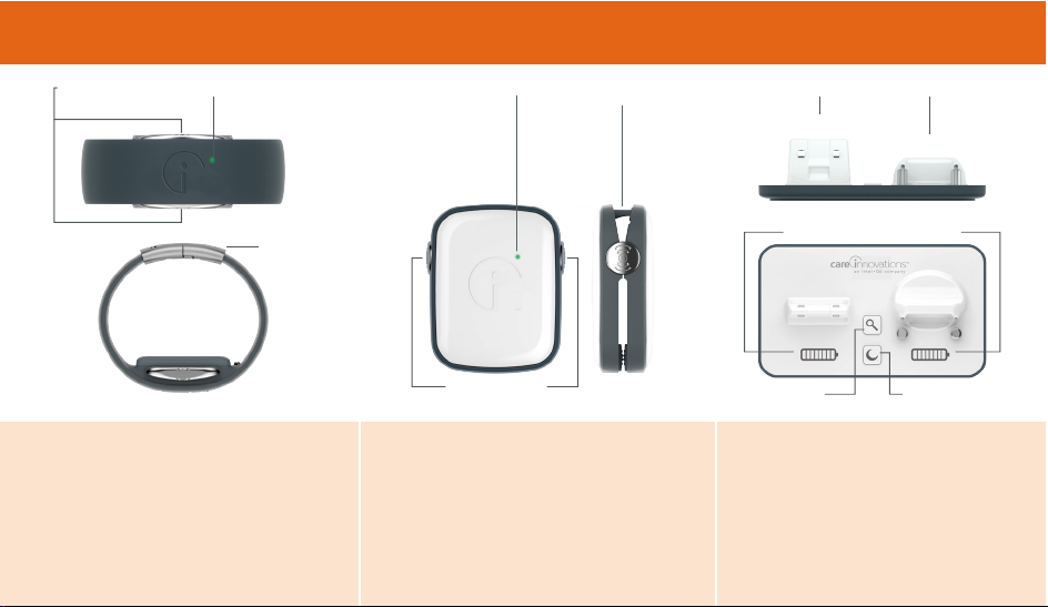
Alert Buttons
Find Clip Night Mode
Battery Level Indicator
Clasp
Alert Buttons Indicator light Indicator light Attachment Peg Charging Areas
Clip
Wristband
WRISTBAND
The Wristband is waterproof and
designed to be worn at all times. It
senses motion and communicates
wirelessly with the Clip and the Dock.
CLIP
The Clip lives on the Dock at home and
is worn or carried when out. It utilizes
the latest location and communication
technology to talk to the systems.
DOCK
The Dock charges the devices and
communicates wirelessly with them,
displaying Clip and Wristband
battery charge levels and helping
find a lost Clip.
WHAT’S IN THE BOX
Page 4
4
WELCOME TO LINK–MOBILE
Care Innovations™ created Link–Mobile to help people
summon and receive help within the early minutes after a
life-threatening event like a stroke, car accident, heart attack
or fall. Timely response can mean recovering faster and
suffering less severe complications.
Link–Mobile pairs a cellular Communications Clip to
a discreet Wristband. The Wristband, which may be
comfortably worn day and night, can be set to manually
or automatically trigger a notification to be sent to friends,
neighbors, and loved ones or directly to our 24-hour a day
Emergency Response Center. The Communications Clip is
a pocket-sized device, so it is easy to take along when you
leave home. Carry it in a purse, wear it on a belt, or clip it
to a car’s seatbelt when driving. In the event of an incident,
your notification, along with your location, will be sent
automatically to the Emergency Response Center, and a text
message and email will be sent to listed personal emergency
contacts, enabling the Communications Clip to receive calls.
INTRODUCTION
In addition to being ready to request help in an emergency,
Wearers can view their daily activity and set personal goals
to encourage healthful movement and other activities.
Immediate access to help minimizes the concern of not
being able to reach out in an emergency.
Page 5
5
IN THIS GUIDE
BEFORE YOU START
Initial Set-up . . . . . . . . . . . . . . . . . . . . . . . . . . . . . . . . . . . . . . . . . . . 6
Activating . . . . . . . . . . . . . . . . . . . . . . . . . . . . . . . . . . . . . . . . . . . . . 7
Fitting the Wristband . . . . . . . . . . . . . . . . . . . . . . . . . . . . . . . . . . . . 8
Testing Communication Between the Wristband
and the Communications Clip . . . . . . . . . . . . . . . . . . . . . . . . . . . . 10
Testing Communication Between the Clip and
the Mobile Phone Network . . . . . . . . . . . . . . . . . . . . . . . . . . . . . . 10
USING LINK–MOBILE
Using the Lanyard and Key Ring . . . . . . . . . . . . . . . . . . . . . . . . . . . 11
The Key Ring Clip . . . . . . . . . . . . . . . . . . . . . . . . . . . . . . . . . . . . . . 11
Attach to Your Key Ring . . . . . . . . . . . . . . . . . . . . . . . . . . . . . . . . . 11
Using Link–Mobile to Send an Alert for Help . . . . . . . . . . . . . . . . . 11
Manual Alert . . . . . . . . . . . . . . . . . . . . . . . . . . . . . . . . . . . . . . . . . . 12
Ty pe s o f Al e rt s . . . . . . . . . . . . . . . . . . . . . . . . . . . . . . . . . . . . . . . . . 13
Cancelling an Automatic Fall Alert . . . . . . . . . . . . . . . 14
Ty pe s o f Se r vi c e P l an s . . . . . . . . . . . . . . . . . . . . . . . . . . . . . . . . . . . 15
Using the Dock . . . . . . . . . . . . . . . . . . . . . . . . . . . . . . . . . . . . . . . . 18
Finding Your Communications Clip . . . . . . . . . . . . . . . 18
Night Mode . . . . . . . . . . . . . . . . . . . . . . . . . . . . . . . . . 18
Leaving Home . . . . . . . . . . . . . . . . . . . . . . . . . . . . . . . 18
Flight Mode and Alerts . . . . . . . . . . . . . . . . . . . . . . . . . . . . . . . . . . 19
Link–Mobile Dashboard . . . . . . . . . . . . . . . . . . . . . . . . . . . . . . . . . 19
Setting up Emergency Contacts . . . . . . . . . . . . . . . . . 20
How to Set up Users . . . . . . . . . . . . . . . . . . . . . . . . . . 20
Activity . . . . . . . . . . . . . . . . . . . . . . . . . . . . . . . . . . . . 20
Locate . . . . . . . . . . . . . . . . . . . . . . . . . . . . . . . . . . . . . 21
Zones . . . . . . . . . . . . . . . . . . . . . . . . . . . . . . . . . . . . . . 21
Notifications . . . . . . . . . . . . . . . . . . . . . . . . . . . . . . . . . 22
Airline Mode . . . . . . . . . . . . . . . . . . . . . . . . . . . . . . . . 22
Disable Auto Fall Alert . . . . . . . . . . . . . . . . . . . . . . . . . 22
Updates . . . . . . . . . . . . . . . . . . . . . . . . . . . . . . . . . . . . . . . . . . . . . . 22
Using Help. . . . . . . . . . . . . . . . . . . . . . . . . . . . . . . . . . . . . . . . . . . . 22
ADDITIONAL INFORMATION
Link–Mobile Troubleshooting Guide . . . . . . . . . . . . . . . . . . . . . . . 23
Link–Mobile Dashboard Troubleshooting Guide . . . . . . . . . . . . . . 29
Safety/Regulatory . . . . . . . . . . . . . . . . . . . . . . . . . . . . . . . . . . . . . . 32
LED and Vibration Codes . . . . . . . . . . . . . . . . . . . . . . . . . . . . . . . . 38
Contact Information . . . . . . . . . . . . . . . . . . . . . . . . . . . . . . . . . . . . 40
Page 6
6
IN ITIA L SE T-UP
Prior to using your Link–Mobile system for the first time, it
is important to charge all components fully. This will take
approximately three hours.
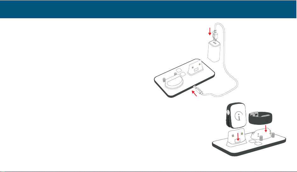
To charge the system, plug one end of the white charging
cable into the Dock, and insert the other end of the cable
into the AC power adaptor. Plug the AC power adaptor
into an electrical outlet.
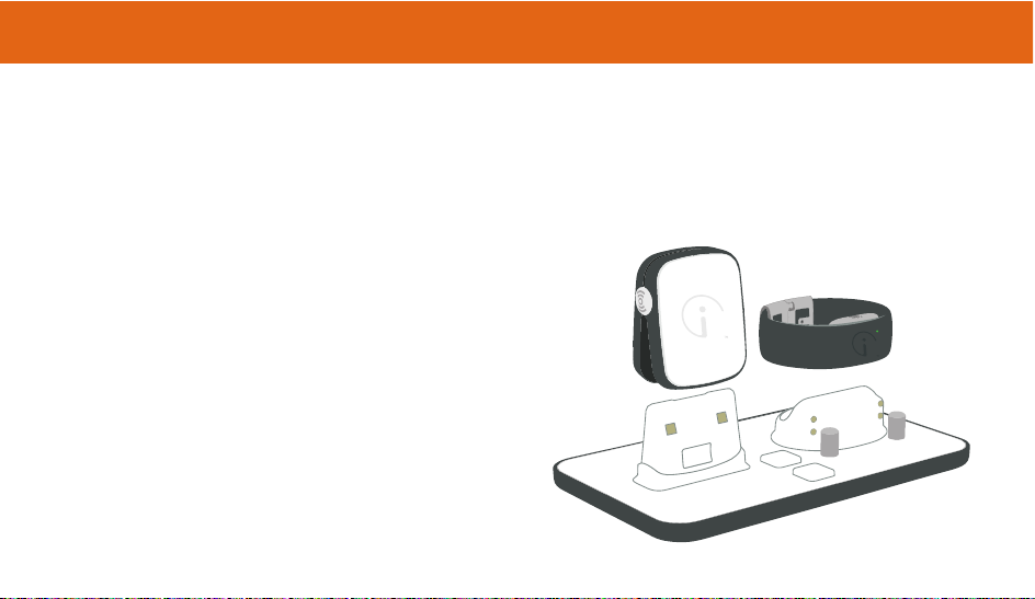
To charge the components of your Link–Mobile system, first
place the Wristband on the charging Dock, then place the
Communications Clip on the charging Dock, as shown in
the photo. The LEDs in the Wristband and Communications
Clip will briefly light green when properly seated.
When you are at home, the Clip can be left on the Dock
and will always be charging. The Night Mode button on the
Dock allows you to dim the LEDs at night. Should the Clip
be misplaced while in the range of the Dock, pressing the
Find Clip button on the dock will cause the Clip to send out
BEFORE YOU START
Cli p lef t on Dock will be ke pt
fully charged.
Wri stb and a nd Cl ip LE Ds
wil l bri efly light green w hen
pro per ly se ated, blin k green
whi le ch arg ing, then be so lid
green when fully charged.
Page 7
7
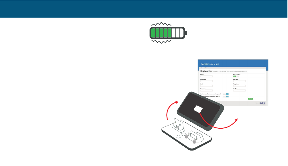
a locator tone. There is a battery level indicator on the Dock
in front of each component’s charging slot. The battery icons
on the Dock show how much charge your components have,
even when the components are not attached.
All battery level indicator bars will be green and will no
longer roll when the system is fully charged.
ACTIVATING
To s e t u p yo u r L i n k –M o b il e sy s t em , go t o www.Link-Mobile.com
or call our Customer Care center at 855-885-CARE (2273). To
complete the set up, you will need your unique Set ID, which is
located on the bottom of your charging Dock.
Online Set-Up: If using the website to set up your system,
follow the on-screen prompts. When you call to test your
system, you will be asked to confirm your profile and settings.
Phone Set-Up: When calling the Customer Care center, a
representative will walk you through the set-up steps
including fully testing your system.
BEFORE YOU START
Night Mode bu tto n turn s o ff charging and
battery in dic ato rs on Dock and a tta che d
devices (does not disable Panic or Find LEDs).
Page 8
8
FITTING THE WRISTBAND
The waterproof Wristband is so comfortable it can be
worn around the clock, even when you sleep. To get the
most comfortable and stylish fit, you can customize its
size. Before fitting your Wristband, you will need to have
the following items available to you: scissors, Phillips head
screwdriver, and pencil or pen. Begin by cutting the paper
ruler from the bottom of the Quick Start Guide.
CAUTION: Before cutting the Wristband, confirm that it
works by completing your initial set-up and testing with the
Customer Care center.
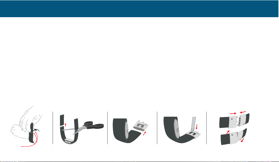
1. To get a measurement for the size of your Wristband,
wrap the paper ruler around your wrist and note the inch
measurement that best indicates a loose, comfortable
fit. Your Wristband should fit snugly enough so you feel
the vibrations when the alert is activated without having
it feel too tight. Because your wrist size can fluctuate
throughout the day due to changes in temperature, your
circulation, and the medications you take, you need to
experiment a bit.
CLOSE
OPEN
MARK
BEFORE YOU START
Page 9
9
2. Set the paper ruler on a flat surface and place the
Wristband next to it. Ensure that the center of the
Wristband is aligned with the middle of your paper ruler
measurement. Mark both ends of your measurement
onto the Wristband (using a pen or pencil) to indicate
where you will need to cut.
3. To best customize the fit of your Wristband, cut just a
little off each end at first and wear it at least twenty-four
hours. Remember, if it’s too big, you can always trim it
shorter, but you can’t add length back.
4. Fit a clasp onto each end of the Wristband strap with the
plain side facing outwards. While you’re experimenting
with the fit, simply attach the silver clasps without
pressing down on the locking tabs.
5. Once you have determined the right fit for you, press
down the locking tabs on the clasps until they tightly
bite into the Wristband. (You may use a screwdriver as
leverage for this step.)
6. The two clasps on the Wristband connect magnetically.
To u n d o i t, pu s h o n t h e t w o d ot s an d t w i st th e c l a sp s .
BEFORE YOU START
Page 10
10
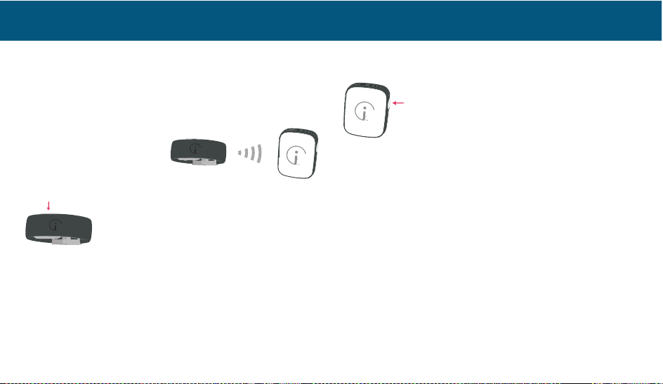
TE STIN G CO MMUN ICAT ION BET WEEN THE
WRISTBAND AND THE COMMUNICATIONS CLIP
For proper operation, your Wristband needs to be in range
of the Communications Clip. This works best at distances
less than 150 feet in open air, but this range can diminish
based on obstacles such as
walls, doors, construction
materials, and other
electronic systems.
To test if the Wristband is in range of the
Clip, press and hold one button (either) on
the Wristband for one second.
If you are within range of the Communications Clip, the
Wristband will vibrate once and the LED will flash green
three times. If the Wristband is too far from the Clip, the
Wristband LED will flash red and an Alert will be sent to
your emergency contacts. If the LED flashes red when in
close proximity to the Clip, refer to the Troubleshooting
Section for resolution.
TE STIN G CO MMUN ICAT ION BET WEEN THE CLI P
AN D TH E MO BILE PH O NE NETW ORK
The Link–Mobile Communications Clip needs
a cellular network signal to operate properly.
To test cellular network strength, press and
hold either button on the Clip for one second
or until a short and long vibration pulse can be felt.
Within five minutes, the LED will flash orange where the
number of flashes indicates relative cellular signal strength:
U Three flashes: strong signal
U Two fla s h es : a v e ra g e s ig n a l
U One flash: weak, but usable signal
U If the LED flashes red, refer to the Troubleshooting
Section.
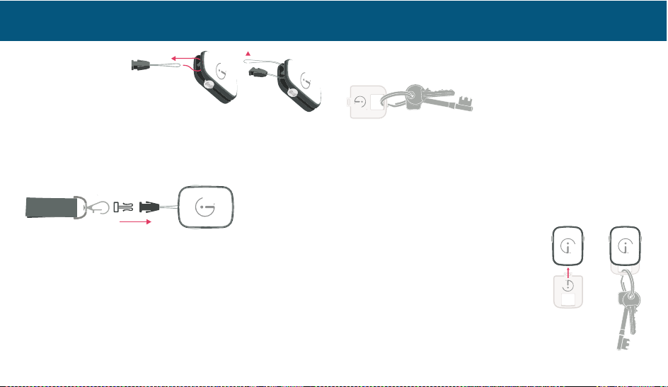
USING THE LANYARD AND KEY RING
There are two methods for attaching the lanyard:
A) looping the lanyard connector thread through the
Clip’s top peg and B) using the quick attach Accessory
BEFORE YOU START
One Second
Page 11
11
Plate. To use the
Communications
Clip’s peg, loop the
lanyard line around
the peg and back over itself as shown.
To wear the Clip via the lanyard, attach the black plastic
connector looped through the Clip directly to the
connector on the lanyard.
Clip together
This black connector can also be used to attach the key ring
to the Communications Clip.
THE KEY RING CLIP
Attach the white Accessory Plate your key ring. (HINT: This
bright white plate acts as a great reminder to grab the
Communications Clip when leaving home, even if you don’t
actually attach the Clip to the Accessory Plate!)
ATTACH T O Y O U R K E Y R I N G
To attach your keys to the Communications Clip, simply
pinch the Clip open and insert the Accessory Plate, tab first.
When you return from your outdoor adventure, remove the
Accessory Plate from the Clip and place the Clip back on
the Dock to charge.
USING LINK–MOBILE TO SEND
AN ALERT FOR HELP
Link–Mobile can send an Alert for help
in two ways:
U Manual — The Wearer intentionally
pinches the Wristband or Clip buttons
to request help
USING LINK–MOBILE
Page 12
12
U Automatic — The Link–Mobile Wristband senses a
possible fall
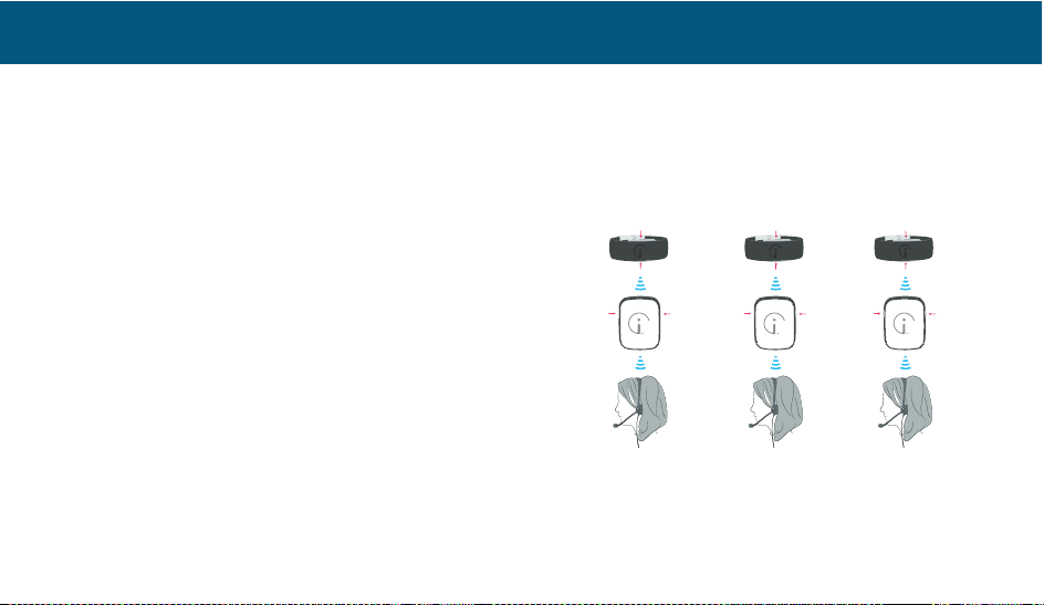
MANUAL ALERT
You can send a request for help by squeezing both buttons
at the same time on either the Communications Clip or
the Wristband. In acknowledgement of your request,
both the Clip and Wristband vibrate and the LED pulses
blue continuously. The Clip sends an Alert signal to the
Help Center computers. Depending on your service plan
(Personal, Personal with Escalation or Professional), this
Alert signal either:
1. Sends an SMS* and email to your designated emergency
contacts — (Personal)
2. Sends an SMS and email to your designated
emergency contacts and then waits four minutes for an
acknowledgement** before escalating to the Emergency
Response Center — (Personal with Professional
Escalation)
3. Directly alerts the Emergency Response Center of your
need for assistance — (Professional)
* Wh en yo ur em erg ency conta ct recei ves t his S MS, m ess ag e r ates
may apply.
** Ackn owled gment s a re pe rform ed by emer gen cy co ntact s who
follow a link in the SMS or Alert email within the time allowed.
Personal Personal with Professional
Professional Escalation
USING LINK–MOBILE
Page 13
13
TYPES OF ALERTS
Your Link–Mobile system sends Alerts when the Wearer
manually requests help by squeezing the buttons on the
Wristband or Communications Clip or when the Wristband
senses movement indicative of a fall.
Clip or Wristband Alert — When the Emergency
Response Center Agent sees an Alert, the Agent will call
the Wearer via the Communications Clip to ascertain their
needs and then seek to arrange the appropriate assistance.
Following the Wearer’s predefined sequence, emergency
contacts will be notified by phone. If help is needed from
local emergency service providers (police, ambulance, fire,
EMT), the Agent will contact them on behalf of the Wearer.
If the Emergency Response Center Agent cannot make
contact with or hear the Wearer, a call will be made
to the emergency contacts in the order listed in the
Wearer’s profile. When the call to the Communications
Clip has ended, the Link–Mobile Communications Clip
will automatically be reset by the Help Center computers,
ready to work again when needed. A tone on the Clip will
indicate the voice communications session has ended.
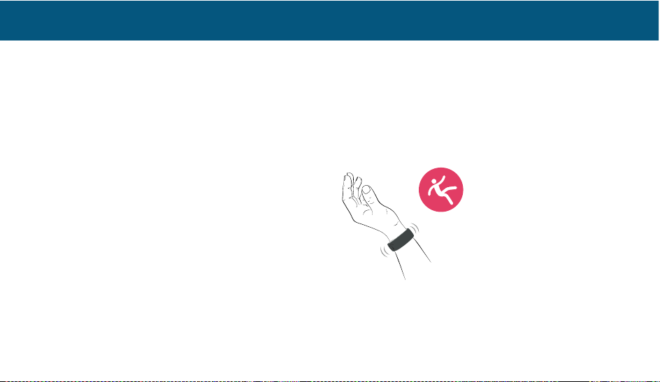
Automatic Fall Alert — If the Wristband detects an event
such as an abrupt shock or rapid change in acceleration,
the Link–Mobile system is designed to interpret this as a
potential fall. Both the Wristband and the Clip will vibrate
and the LED on both will flash blue continuously.
If in range, the Wristband will send an Alert to the
Communications Clip, which then sends an Alert signal to
the Help Center computers over the cellular network.
USING LINK–MOBILE
Page 14
14
Depending on your service plan, this Alert signal triggers
one of three actions:
1. An SMS and email are sent to your designated
emergency contacts
2. An SMS and email are sent to your designated
emergency contacts. If no acknowledgment** is received,
the Emergency Response Center is contacted.
3. The Emergency Response Center is directly alerted of
your need for assistance
** Ackno wledg ments are per formed by em erg ency conta cts w ho
follow a link in the SMS or Alert email within the time allowed.
Cancelling an Automatic Fall Alert
1. If an Alert is triggered accidentally, it can be cancelled
before the Alert signal is sent to the Help Center
computers. To cancel an Alert, squeeze and hold both
buttons on either the Clip or the Wristband until the LED
on both units briefly flashes green and then goes out.
2. NOTE: As a safety feature to protect a confused Wearer,
if both buttons are squeezed three or more times within
thirty seconds, the Alert cannot be cancelled and will
be sent to the Help Center computers. This will be
treated as an Alert and, depending on your service plan,
predefined response actions will follow.
In addition, Link–Mobile can trigger an Alert to be sent to
emergency contacts (SMS and email notifications) on other
monitored events including:
Low Battery — If Clip or Wristband battery levels are
too low, the LED on the respective device will flash
amber intermittently until the unit is placed on the Dock
and battery levels recover. NOTE: Please allow three
hours for a full charge.
Out of Range — If the Clip cannot communicate
with the cellular network or the Wristband cannot
communicate with the Clip, the LED on the respective
device will pulse red twice every five seconds. The red
USING LINK–MOBILE
Page 15
15
flashing LED will go out when communications are
restored.
Activity — If the activity measured by the Wristband is
either above or below a threshold set in the Link–Mobile
Dashboard, an Alert is sent. No indication of this Alert is
portrayed on the Wristband or Clip.
Zone — If the Communications Clip enters a restricted
map area or leaves a safe map area outside designated
hours, an Alert is sent. No indication of this Alert is
portrayed on the Wristband or Clip.
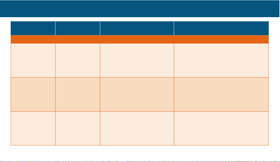
TYPES OF SERVICE PLANS
Personal — All Alerts, including Panic and Fall, are sent
only to emergency contacts (friends/family/neighbors), as
defined in the Wearer’s profile.
Personal with Professional Escalation — Clip and
Wristband Alerts are sent to emergency contacts AND
will roll to the Emergency Response Center if not
acknowledged, within four minutes, by a click on the
link contained in the SMS/Email. After the Emergency
Response Center Agent acts, an email will be sent to all
emergency contacts summarizing the actions taken (afterincident report). All other non-emergency Alerts are sent
directly to emergency contacts only. NOTE: The links in
the email and SMS are active for fifty minutes, after which
they expire.
Professional — Clip and Wristband Alerts are sent directly
to the Emergency Response Center. An email is sent to all
emergency contacts summarizing the actions taken (afterincident report). All other non-emergency Alerts are sent
directly to emergency contacts only.
Professional Plus — This service plan includes all
the features of the Professional plan, plus advanced
functionality and enhanced alert monitoring and reporting.
Contact Customer Service for more information about this
service plan.
USING LINK–MOBILE
Page 16
16
Service Plan/
Alert Type
Personal
Personal with Escalation
to Professional
Professional
Emergency Alerts
Clip Alert Alert to emergency
contacts.
Alert to emergency contacts.
Unacknowledged roll to
Emergency Response Center.
After-incident email to
emergency contacts.
Notification directly to Emergency
Response Center. Emergency Response
Center calls Wearer and emergency
contacts in sequence. After-incident email
to emergency contacts.
Wristband Alert Alert to emergency
contacts.
Alert to emergency contacts.
Unacknowledged roll to
Emergency Response Center.
After-incident email to
emergency contacts.
Notification directly to Emergency
Response Center. Emergency Response
Center calls Wearer and emergency
contacts in sequence. After-incident email
to emergency contacts.
Wristband Fall Alert to emergency
contacts.
Alert to emergency contacts.
Unacknowledged roll to
Emergency Response Center.
After-incident email to
emergency contacts.
Notification directly to Emergency
Response Center. Emergency Response
Center calls Wearer and emergency
contacts in sequence. After-incident email
to emergency contacts.
USING LINK–MOBILE
Page 17
17
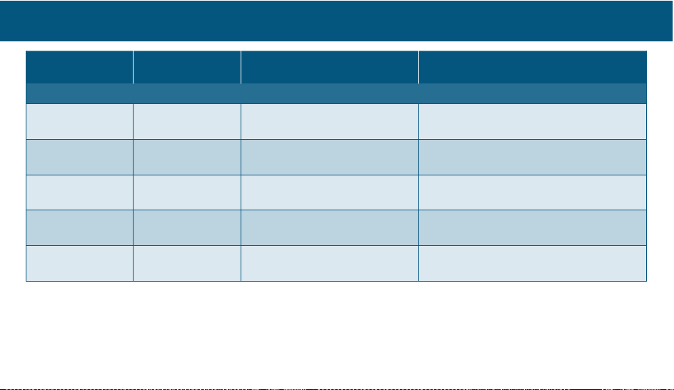
Service Plan/
Alert Type
Personal
Personal with Escalation
to Professional
Professional
Informational Alerts
Low Battery (Clip
and Wristband)
Alert to emergency
contacts only.
Alert to emergency contacts only.
This Alert does not escalate.
Monitoring through escalation available
with Professional Plus.
Wristband Out of
Range
Alert to emergency
contacts only.
Alert to emergency contacts only.
This Alert does not escalate.
Monitoring through escalation available
with Professional Plus.
No Cell Signal Alert to emergency
contacts only.
Alert to emergency contacts only.
This Alert does not escalate.
Monitoring through escalation available
with Professional Plus.
Activity Alert
(hi or low)
Alert to emergency
contacts only.
Alert to emergency contacts only.
This Alert does not escalate.
Monitoring through escalation available
with Professional Plus.
Zone
(enter or exit)
Alert to emergency
contacts only.
Alert to emergency contacts only.
This Alert does not escalate.
Monitoring through escalation available
with Professional Plus.
USING LINK–MOBILE
Page 18
18
USING THE DOCK
Finding your Communications Clip
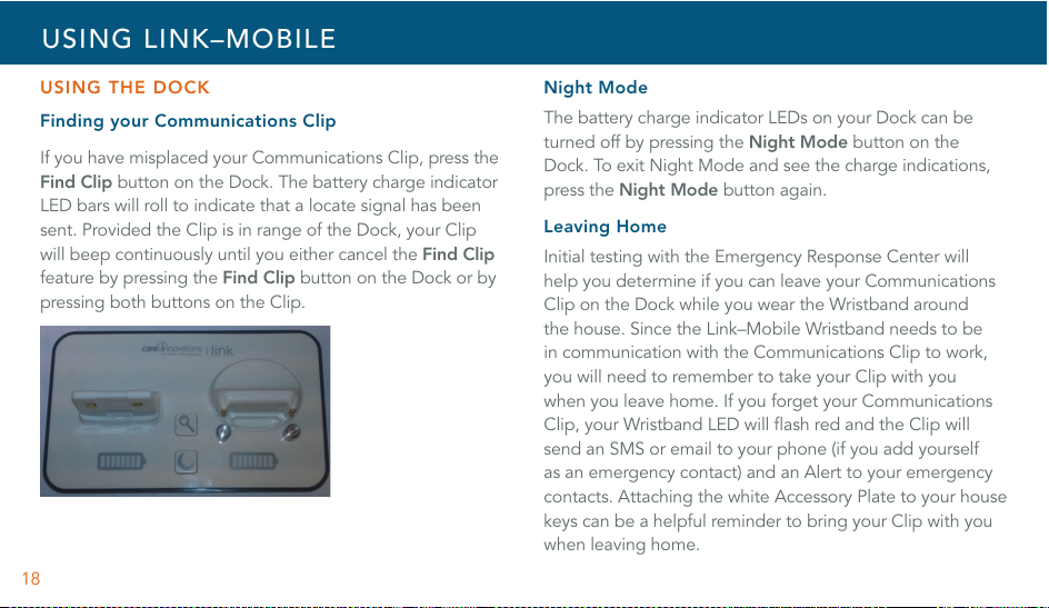
If you have misplaced your Communications Clip, press the
Find Clip button on the Dock. The battery charge indicator
LED bars will roll to indicate that a locate signal has been
sent. Provided the Clip is in range of the Dock, your Clip
will beep continuously until you either cancel the Find Clip
feature by pressing the Find Clip button on the Dock or by
pressing both buttons on the Clip.
Night Mode
The battery charge indicator LEDs on your Dock can be
turned off by pressing the Night Mode button on the
Dock. To exit Night Mode and see the charge indications,
press the Night Mode button again.
Leaving Home
Initial testing with the Emergency Response Center will
help you determine if you can leave your Communications
Clip on the Dock while you wear the Wristband around
the house. Since the Link–Mobile Wristband needs to be
in communication with the Communications Clip to work,
you will need to remember to take your Clip with you
when you leave home. If you forget your Communications
Clip, your Wristband LED will flash red and the Clip will
send an SMS or email to your phone (if you add yourself
as an emergency contact) and an Alert to your emergency
contacts. Attaching the white Accessory Plate to your house
keys can be a helpful reminder to bring your Clip with you
when leaving home.
USING LINK–MOBILE
Page 19
19
FLIGHT MODE AND ALERTS
Your Co mmuni catio ns Cl ip ca n be p laced in a stan dby
mode, designed to meet FAA requirements for turning off
cellular devices during aircraft travel. To enter Flight Mode,
press a single button on either the Clip or the Wristband
five times in a row. Each press will be accompanied by a
brief vibration pulse. To signal you have successfully set the
Clip in Flight Mode, the LED on both units will blink purple.
To exit Flight Mode, press and hold one button on Clip or
Wristband. This will need to be done for BOTH units.
Flight Mode can also be initiated from the Flight Mode icon
within the Wearer section of the Link–Mobile Dashboard.
LINK–MOBILE DASHBOARD
The Link–Mobile Dashboard provides anytime access to
defining a host of parameters for your Link–Mobile system
use. To provide access to the Dashboard, Care Innovations
sends a hyperlink to the original purchaser’s (called the
Dashboard Manager) email as part of the welcome email or
one may visit www.Link–Mobile.com. NOTE: On your first
use, click on the Profile icon to add telephone details and
select your own password. Click update when done. Your
Link–Mobile system is activated and assigned to the Wearer
identified at the time of purchase. The Dashboard Manager
is able to use these Icons:
Create a list of Users who are granted access to
the Dashboard (restricting what users can see
and what they may change).
Locate — a Wearer’s Clip on a street and satellite
map to see current and past locations, routes
taken, battery level and charging status.
Notifications — See a history of Alerts
including GSM and GPS strength and
charging status.
USING LINK–MOBILE
Page 20
20
Alert Contacts — Define who should be notified
in the event the Wearer needs help (including
which Alerts, what day, what time of day and
method by which they are to be notified).
Zones — Define safe and unsafe locations by
drawing on a map. Define expected day and
times for each given location.
Activity — Observe activity levels. Define bed
time, wake time, and low and high level Alerts
based on activity level.
Setting up Emergency Contacts
Log in at www.Link–Mobile.com, select the
Contacts icon. You can add names and contact
details (phone, SMS, email). From within the
Wearer section, one may assign Alert Contacts
to a Wearer by clicking the Alert Contacts icon. In this
section, one may also indicate relationship, availability and
contact times, and one may configure which Alert
notifications each emergency contact will receive, including
when (day/time) and how (phone/SMS/email) they will
receive them.
The order in which emergency contacts are contacted by
the Emergency Response Center is defined by dragging
them into an order and clicking update order.
How to Set up Users
Log in at www.Link–Mobile.com, select the
Users icon. One may grant viewing permissions
and invite other users to see select Wearer
information or respond to a Wearer’s request
for help.
Activity
Log in at www.Link–Mobile.com, select the
Wearer icon, and then click on the Activity icon
to see activity levels. Users may review activity
USING LINK–MOBILE
Page 21
21
levels and set up Alert notifications levels for unusually high
or low levels of activity. One may filter this list to view
activity by a date range.
Locate
Log in at www.Link–Mobile.com, select the
Wearer icon, and then click on the Locate icon.
One may filter for a given date range of historic
locations and even download a PDF copy of a
route traveled to share with friends. From here, one
may also make a request for the system to find the
Communications Clip’s current location. To see current
location, select Update Location. The process of locating
the Clip and reflecting its location on the map can take up
to five minutes. If you are having trouble locating the
Communications Clip, refer to the Troubleshooting section
of this manual. Status of the Clip and Wristband (including
if on the charging Dock, battery level, and street view) can
be seen from the table. Select the map type (street,
satellite, hybrid) by checking the blue plus sign in the upper
right section of the map. Zoom in or out until you can see
your desired geography.
NOTE: Since GPS signals can waiver and report spurious
locations, selecting “Significant Only” forces the system
to limit signals to only the strongest and most consistent
signals.
Zones
Log in at www.Link–Mobile.com, select the
Wearer icon, and then click on the Zone icon.
Clicking on Add a Zone allows users to
graphically depict Safe and Unsafe areas. By
defining a zone, you can then set up a Notification to be
sent to emergency contacts should a Wearer leave an area
or not enter an area by a given time. Alerts, based on day
and time of day, can be defined for entering or leaving
these zones. Start by naming your zone and entering a
starting street address. Select the map type (street, satellite,
hybrid) by checking the blue plus sign in the upper right
section of the map. Zoom in or out until you can see your
USING LINK–MOBILE
Page 22
22
desired geography. Click on the map to establish a starting
point for a shape which will surround your area of interest,
and continue to move the cursor around in a shape which
defines your zone. Up to eight outline points may be
defined. End defining your shape by double clicking.
Define the type of zone (Inclusion — an area where a user is
expected to be or Exclusion — an area where a user is not
allowed to enter) and when Alerts should be sent, based on
day, time, and location within or outside of these zones.
Notifications
Log in at www.Link–Mobile.com, select the
Wearer icon, and then click on the
Notifications icon. Here you will find a list
of communications received from Link–
Mobile and sent to the Help Center computers. One may
filter this list to find particular notifications by type or date
range. The status of battery charge and cellular and GPS
signal strengths are also shown.
Airline Mode
(coming later) Gareth to confirm w/c 24/3
Disable Auto Fall Alert
(coming later) Gareth to confirm w/c 24/3
UPDATES
Link–Mobile is designed to stay
current by receiving software
updates, including enhancements and corrections “over
the air.” These updates will take place in the background.
When an update is completed, the user will notice a short
LED sequence as each unit restarts.
USING HELP
For the most current information about your Link–Mobile
system, click on the help icon, located near your logon
name. You will find updates to this printed manual, helpful
videos, best practices, tips and ideas to improve your
Link–Mobile experience.
USING LINK–MOBILE
Page 23
23
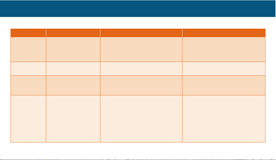
LINK–MOBILE TROUBLESHOOTING GUIDE
Symptom Items to Check You Sho ul d Se e Resolution
Link–Mobile is
not working
Is there power to
charging Dock?
Do the Dock LEDs light up when
plugged in? Should be plugged
into a known working outlet, not
controlled by a light switch.
Remove A/C adaptor from wall plug,
remove cord from adaptor. Replug
cord and adaptor. Verify LEDs light up
briefly on the Dock.
Is the device charged? Do any of the LEDs light up (Clip,
Wristband) when placed on the Dock?
See LED matrix. Red indicates charge
is needed. Contact Customer Care.
Are you properly
placing devices on
charging Dock?
Verify that when seated, the device
LED flashes green for 5 seconds
If LED is any color other than Green,
contact Customer Care.
WARNING: This
troubleshooting step
may trigger your
emergency contacts
or the Emergency
Response Center to
see an Alert and
contact you.
Pinch buttons. Confirm both
Wristband and Communications Clip
vibrate and LEDs flash blue.
If connected to the Emergency
Response Center, report this was
a test.
If devices do not vibrate nor does the
LED flash, contact Customer Care.
ADDITIONAL INFORMATION
Page 24
24
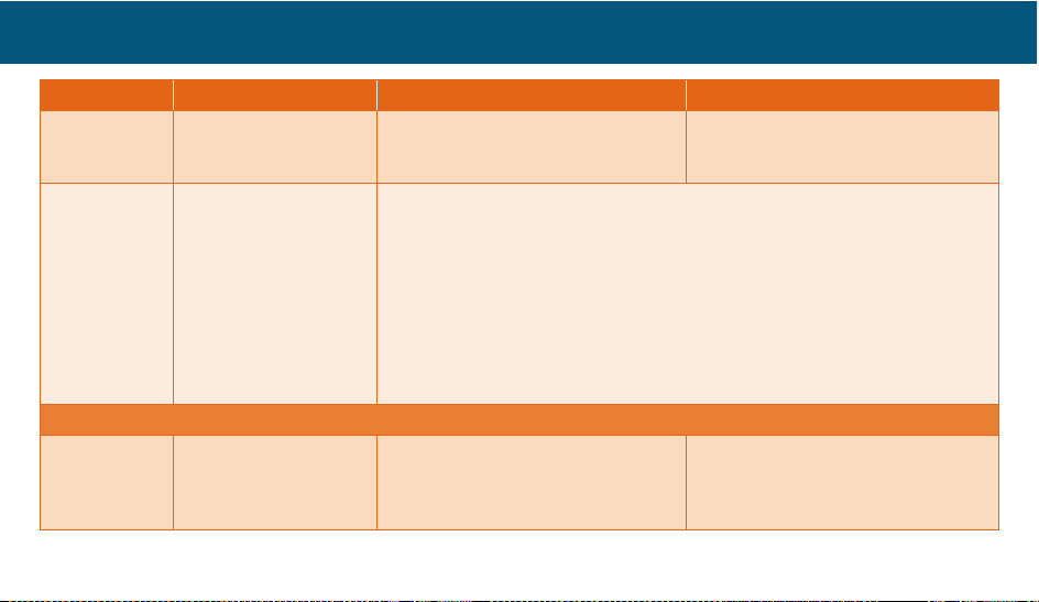
Symptom Items to Check You Sho ul d Se e Resolution
Device LEDs
light, but not
Dock LEDs
Have the LEDs on the
Dock been put into
sleep mode?
Confirm LEDs on Clip and Wristband
light green when placed on Dock.
Press LED Sleep button on Dock twice
(like a door bell).
Dock LEDs
light briefly,
but then
immediately
go back out…
Has power to the Dock
been interrupted?
1. Remove devices from Dock.
2. Unplug A/C adaptor from wall.
3. Unplug cord from A/C adaptor and Dock.
4. Wait ten seconds.
5. Plug cord into A/C adaptor and Dock, making sure they connect tightly.
6. Plug in A/C Adaptor.
7. First, replace Wristband on Dock until Dock LEDs light up.
8. Then, replace the Clip.
9. LEDs on Dock should now work. If not, contact Customer Care.
Excessive Notifications sent to Emergency Contacts
Excess Panic
Alerts
These notifications come when
the Wearer squeezes the buttons
either on the Wristband or the
Communications Clip.
Be sure the Wearer is familiar with
how to cancel erroneous requests.
(Press both buttons again)
ADDITIONAL INFORMATION
Page 25
25
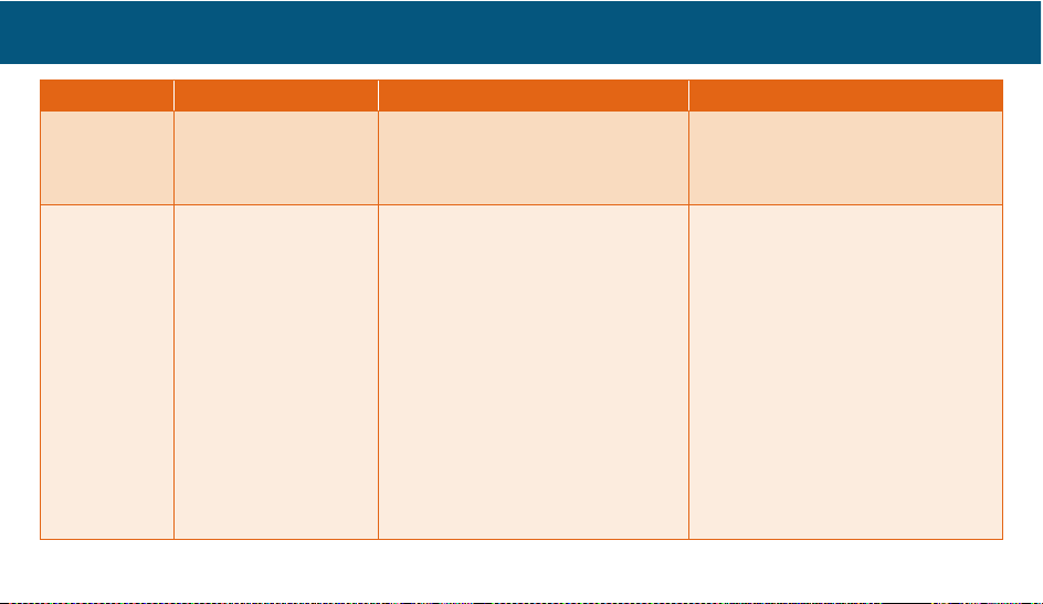
Symptom Items to Check You Sho ul d Se e Resolution
Excess Auto
Fall Alerts
Consider changing
from wearing on wrist
of “dominant” hand to
the other hand.
Consider adjusting or disabling
Auto Alert by calling the Emergency
Response Center or visiting
www.Link–Mobile.com.
If you still have questions, contact
Customer Care.
Excess Low
Battery Alerts
NOTE: Batteries in
the Wristband and
Communications Clip
are lithium ion type
and do not suffer from
“memory” problems
typical in previous
rechargeable battery
technologies. Wearers
do not need to allow
devices to periodically
discharge in order to
extend recharge life.
Both the Wristband and
Communications Clip will indicate
to the Wearer when they need
recharging via the LED on the device,
the LEDs on the charging Dock, and
by sending an SMS/email to those
whose profile indicates they should
receive such notices.
Expected life after a full charge is
three days for the Communications
Clip and seven days for the
Wristband. Please allow devices to
remain on the charging Dock for
at least three hours to obtain a full
charge.
To reduce the number of notices
about battery, instruct the Wearer to
return the devices to the charging
Dock when the LEDs on the Dock
indicate a recharge is required.
If you still have questions or believe
battery life is too short, contact
Customer Care.
ADDITIONAL INFORMATION
Page 26
26
Symptom Items to Check You Sho ul d Se e Resolution
Zone Alerts
The Communications
Clip generates an
Alert based on
parameters defined
by the Dashboard
manager, who defines
a geographic area
from which the Wearer
exits (inclusion zone) or
enters (exclusion zone).
In ideal conditions, the GPS signal
received by the Communications
Clip can indicate a location within
three meters of actual location.
Areas with tall buildings or placing
the Communications Clip in an area
with an obstructed view of the sky
can result in the device mistakenly
reporting a location at the far edge of
device accuracy, often more than 300
meters from its actual location.
To reduce the number of notices
about zones, be sure that the zone
has been drawn large enough to
account for occasional stray GPS
signals. For help drawing, see
demonstration video on
www.Link–Mobile.com under Help.
If you still have questions or need
help creating zones, contact
Customer Care.
ADDITIONAL INFORMATION
Page 27
27
Symptom Items to Check You Sho ul d Se e Resolution
Out of Range
Alerts
The radio link between
the Communications
Clip and the Wristband
can be reliably
maintained at distances
of up to 150 feet in
clear space.
A home’s construction
materials and
interference from other
devices can reduce the
distance the Wristband
can travel from the
Communications
Clip and still retain a
connection.
A break in the
connection is reported
on the Wristband by a
red LED.
A range test can be performed at any
time by placing the Communications
Clip on the Dock in the desired
recharging location and pressing
one side of the Wristband button.
Do this while wandering around the
living space. A green LED on the
Wristband indicates a completed
connection with the Communications
Clip. The number of flashes (one to
three) indicates signal strength where
three is the strongest. A red LED
indicates the Wristband is no longer
communicating with the Clip.
To reduce the number of notifications
about the Wristband being out
of range, the Wearer should carry
the Communications Clip when
they expect to move beyond the
range that can reliably maintain a
connection.
If you still have questions, contact
Customer Care.
ADDITIONAL INFORMATION
Page 28
28
Symptom Items to Check You Sho ul d Se e Resolution
No Comms
Alerts
The Communications
Clip requires a cellular
signal to send its
information to the
Emergency Response
Center.
Atmospheric conditions, a home’s
construction materials and
interference from other devices
can reduce the signal transmission
between the Communications Clip
and cell towers.
Since this can be intermittent,
Dashboard managers have the ability
to adjust the time interval before the
Emergency Response Center will
send a notification to emergency
contacts saying that the connection
with the Communications Clip and
the cell tower has been lost.
To reduce the number of notifications
about the Communications Clip losing
connection with the cellular network,
considering adjusting the “Device not
Communicated” slider to the right
(slider can be found under Contacts
section under System Notifications).
Be aware that the ability to notify
emergency contacts in the event of a
panic or fall is not possible when the
Communications Clip is not receiving
a cellular signal.
If you still have questions, contact
Customer Care.
ADDITIONAL INFORMATION
Page 29
29
LINK–MOBILE DASHBOARD TROUBLESHOOTING GUIDE
Symptom Items to Check You Sho ul d Se e Resolution
Link–Mobile
Dashboard is
not available
The web address is
https://www.Link–Mobile.com
Yo u sh o ul d se e a p ro m pt f o r us e r
name (email address) and password.
Yo u ca n s el ec t Forgotten your
Password to have a new password
sent to the email address of the
Dashboard Manager.
Contact Customer Care. Proof
of identify and purchase will be
required.
Receiving
Excessive Zone
Alerts
The size of the zone should
be larger than the expected
travel range of the Wearer.
You sho uld d raw t he zo ne so that
there is plenty of space around the
area you wish to be alerted should
the Wearer enter or exit during the
days and times specified.
To reduce the number of notices
about zone, be sure that the zone
has been drawn large enough to
account for occasional stray GPS
signals. For help drawing, see
demonstration video on www.
Link–Mobile.com under Help.
If you need help creating zones,
contact Customer Care.
ADDITIONAL INFORMATION
Page 30
30
Symptom Items to Check You Sho ul d Se e Resolution
Location is not
updating
Being inside large structures
(shopping malls) or
surrounded by tall buildings
may obstruct a view of the
sky. This can result in the
device not updating location.
You sho uld s ee th e las t loc ation
where the Communications Clip
had a view of the sky. The last
known location will be indicated
on the map by a red dot. Clicking
on highlight location will show
details about the date and time
this location was recorded.
To refresh a location, click on the
Locate icon, then the Update
Location button. This sends a
signal to the Communications
Clip and requests an update.
If you need help using Locate,
contact Customer Care.
Activity not
showing activity
The Wristband is the device
that monitors and reports
activity.
You should see activity bars in blue
for daytime activity and green for
nighttime activity.
Check the Day time (expected
rising time) and Night time
(expected bedtime) settings.
Click Set before leaving the
page.
ADDITIONAL INFORMATION
Page 31
31
Symptom Items to Check You Sho ul d Se e Resolution
Emergency
contacts
receiving/not
receiving Alerts
The Alert Contacts icon
will show which contacts
are associated with the
Wearer. See the notification
parameters, such as type of
Alert, day and time to send
Alerts.
You should see a valid email
address and SMS # to a phone
capable of receiving text messages
is required.
Update the contact information,
time and date, and Alert types
to be recorded. Be sure to
click Update before leaving
the page. If you need help
using Alert Contacts, contact
Customer Care.
Other Users
unable to see
features
Which privileges users are
granted is defined by the
Dashboard Manager who
sets up User accounts.
ADDITIONAL INFORMATION
Page 32
32
SAFETY/REGULATORY
Installation Guidelines
1. Read and understand all instructions and save them for
future reference.
2. Follow all warnings and instructions marked on the
product.
3. Do not install charging Dock near a bathtub, sink or
shower.
4. Operate this device using only the power source that
is indicated on the marking label. If you are unsure of
the power supply to your home, consult with your local
power company.
5. Do not place this product on an unstable cart, stand or
table. This product may fall, causing serious damage to
the product.
6. Adjust only those controls that are covered by the
operating instructions. Improper adjustment of other
controls may result in damage and will often require
extensive work to restore the product to normal
operation.
7. Clean this product with a soft, damp cloth. Do not use
chemicals or cleaning agents to clean this device.
8. Use only the power supply that came with this unit.
Using other power supplies may damage the unit.
9. Because this device operates on electricity, you should
have an alternate device in your home that could
operate without electricity in case the power in your
home goes out.
10. To avoid interference to nearby appliances, do not
place the Dock or Communications Clip on or near a TV,
microwave oven, or VCR.
Safety Information for Your Device
Read this information before using your device.
ADDITIONAL INFORMATION
Page 33
33
Driving safety
Talking on the Communications Clip while driving can
distract the driver, result in extreme danger and may be
illegal in some states. Remember, safety comes first. Check
the laws and regulations relating to use of the device in the
areas where you drive. Always obey them. If you must use
your device while driving, please:
U Give full attention to driving. Driving safely is your first
responsibility.
U Pull off the road and park before making or answering a
call.
An air bag inflates with great force. DO NOT place objects,
including either installed or portable wireless equipment, in
the area over the air bag or in the air bag deployment area.
If in-vehicle wireless equipment is improperly installed and
the air bag inflates, serious injury could result.
Electronic devices
Your mo bile perso nal e merg en cy re sp onse devi ce is like
a cellular telephone. When it is ON, it receives and also
sends out radio frequency (RF) signals. Most modern
electronic equipment is shielded from RF energy. However,
certain electronic equipment may not be shielded against
the RF signals from your wireless device. Therefore, use of
your device must be restricted in certain situations.
Pacemakers
The Health Industry Manufacturers Association
recommends that a minimum separation of six (6) inches
be maintained between a device and a pacemaker to
avoid potential interference with the pacemaker. These
recommendations are consistent with the independent
research and recommendations of Wireless Technology
Research. Never come closer than six (6) inches to a person
with a heart pacemaker implant when using your device.
Doing so could result in interference with the function of
the pacemaker. Persons with pacemakers:
ADDITIONAL INFORMATION
Page 34

34
U ALWAYS keep the device more than six (6) inches from
your pacemaker when the device is turned on.
U Do not carry the device in a breast pocket or locate it on
the safety belt of your car near your pace maker.
U Use the ear opposite the pacemaker to minimize the
potential for interference.
U If you have any reason to suspect that interference is
taking place, turn your device OFF immediately.
Important Safety Instructions
Follow these safety precautions when using your device to
reduce the risk of fire, electric shock, and injury to persons
or property:
1. Keep any openings of the Communications Clip
unblocked. Do not set the device or Dock on a heating
register or over a radiator. Insure that proper ventilation
is provided at the installation site.
2. Link–Mobile Wristband is water-proof (splash/rain
resistant) IPX6 certified, so it offers water protection.
It can sustain temporary immersion in one meter
(39 inches) of water for up to thirty minutes, so you can
wear it while in the shower. However, it’s not suitable for
extended and continuous water submersion, such as
swimming, snorkeling or diving. Any misapplied usage
of the device in water submersion conditions may cause
permanent damage or may cause it to malfunction.
Range to the Dock and Communications Clip are
impacted when the Wristband is wet or under water.
3. Do not allow anything to rest on the charging Dock.
4. Place the A/C adaptor cable so that it will not be
walked on.
5. Never insert objects of any kind into the product slits, as
that may result in fire or shock.
6. Unplug the Dock from the wall outlet before cleaning.
ADDITIONAL INFORMATION
Page 35
35
7. Do not use liquid cleaners or aerosol cleaners. Use a
damp cloth for cleaning.
8. Do not disassemble this product. If service or repair
work is required, contact the Customer Care helpline
found in this User’s Guide.
9. Do not overload wall outlets and extension cords.
10. Avoid using during an electrical storm.
11. You may choose to use a surge protector to protect
the Dock.
12. Do not use this device to report a gas leak, especially if
you are in the vicinity of the gas line.
Charger
Charging safety
The A/C adaptor designed for this unit requires the use of a
standard 120 V AC power source for its operation.
U Never attempt to disassemble or repair the A/C adaptor.
U Never use the A/C adaptor if it has a damaged or worn
cable or plug.
U Always contact Customer Care if repair or replacement is
required.
U Never alter the cord or plug on your A/C adaptor. If the
plug will not fit into the available outlet, have a proper
outlet installed by a qualified electrician.
General Safety Precautions
Your device is a high quality piece of equipment. Before
operating, read all instructions and cautionary markings on
the product, battery and A/C adaptor. Failure to follow the
directions below could result in serious bodily injury and/
or property damage due to battery liquid leakage, fire or
rupture.
U DO NOT use or store this equipment in a place where
it will be exposed to high temperatures, such as near an
open flame or heat-emitting equipment.
ADDITIONAL INFORMATION
Page 36
36
U DO NOT drop your device or subject it to severe shock.
When not using, return the Communications Clip to the
Dock to avoid possible damage due to mishandling.
U DO NOT expose this equipment to rain or spilled
beverages.
U DO NOT use unauthorized accessories.
U DO NOT disassemble the device or its accessories.
If service or repair is required, return unit to Care
Innovations. If unit is disassembled, the risk of electric
shock or fire may result.
FCC
This device complies with Part 15 of FCC Rules including
interference that may cause undesired operation.
Operation is subject to the following two conditions:
1. This device may not cause harmful interference, and
2. This device must accept any interference received.
This equipment has been tested and found to comply with
the limits for a Class B digital device, pursuant to Part 15
of the FCC Rules. These limits are designed to provide
reasonable protection against harmful interference in a
residential installation. This equipment generates, uses,
and can radiate radio frequency energy. If not installed
and used in accordance with the instructions, may cause
harmful interference to radio communications. However,
there is no guarantee that interference will not occur in a
particular installation. If this equipment does cause harmful
interference to radio or television reception, which can be
determined by turning the equipment off and on, the user
is encouraged to try to correct the interference by one or
more of the following measures:
– Reorient or relocate the receiving antenna.
– Increase the separation between the equipment and
receiver.
– Connect the equipment into an outlet on a circuit
different from that to which the receiver is connected.
ADDITIONAL INFORMATION
Page 37
37
– Consult the dealer or an experienced radio / TV
technician for help.
Compliance with Other FCC Regulations
Operating procedures
Never violate any of the following Rules and Regulations
of the FCC when using your device. Such violations are
punishable by fine, imprisonment or both.
U Never use obscene, indecent, or profane language.
U Never use your device to send false distress signals.
U Never wiretap or otherwise intercept a phone call,
unless you have first obtained the consent of the parties
participating in the call.
U Never make any anonymous calls to annoy, harass, or
molest other people.
U Never charge another account without authorization, to
avoid payment for service.
U Never willfully or maliciously interfere with any other
radio communications.
U Never refuse to yield the line when informed that it is
needed for an Emergency Response. Also, never take
over a line by stating falsely that it is needed for an
emergency.
Intel GE Care Innovations™ Link-Mobile is designed and manufactur ed in th e UK by bu ddi* Ltd.
ADDITIONAL INFORMATION
Page 38
38
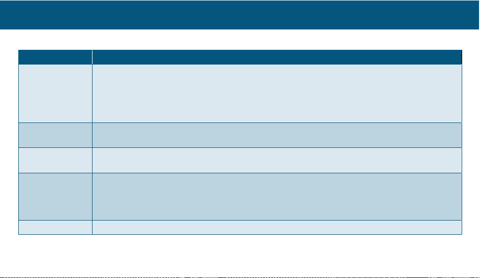
LED AND VIBRATION CODES
Device LED Color Meaning
Green U Clip and Wristband — LED turns Green for five seconds when successfully placed on Dock to
charge, flashes green while charging, then turns steady green on the Dock when fully charged
U When testing if Wristband is in range of Clip, Wristband flashes Green three times
U Clip — When Clip GSM test is successful
U Flashes Green three times to signal successful canceling of an auto or manual Alert
Amber U Pulses periodically to indicate Low battery
U Search for Clip to GSM
Blue U Clip and Wristband flashes upon manual button press
U Wristband and Clip flash Blue upon auto fall detection
Red U Pulses periodically to indicate Wristband out of range of Clip more than five minutes
U Clip pulses red if no GSM signal for more than five minutes
U Wristband flashes Red three times when test shows it is out of range of Clip
U Clip flashes Red three times when test shows it is out of range of GSM
Purple U Solid purple LED indicates Airplane Mode is on.
ADDITIONAL INFORMATION
Page 39
39
Vibration U Wristband will vibrate on fall detection
U Clip and Wristband will vibrate if the other device is triggered and on button press and continual
pulsing until cleared
Button Presses U Activate Alarm — Blue LED rapid flash and vibrate with continual pulses
U Cancel Alarm — Green LED flash five seconds with halting of continual pulses.
To ne f ro m C l ip U Escalating tones when Find Clip is triggered from Dock Ring or perhaps two tones, identical,
repeating — Call connection will begin unless cancelled
LEDs on Dock U Battery Level Bars Seven Green
U Battery Level Bars Four-Seven Green
U Battery Level Bars Two-Three Red — Slow Flash
U Rapid flashing red (One bar)
U Rolling LEDs — Find Clip Initiated
ADDITIONAL INFORMATION
Page 40
40
CONTACT INFORMATION
Our Customer Care team can help address any questions or concerns that you have with your system. Please contact your
Care Innovations Customer Care representative at (855) 885-CARE (2273).
Please note, due to concerns with your privacy, we cannot accept email requests for new service, returns, changes in
emergency contact or Wearer contact information, or lock box code changes.
If you need help with Phone Number Hours
U Placing New Orders
(800) 930-1137
24/7
U Tec h ni c a l S up p o rt
U Shipping Status
U Return Requests
U Setting up new equipment
U Initial or periodic testing
U Updating Wearer or contact information
(855) 885-CARE (2273)
24/7
8:00am- 5:00pm Pacific Time
(Monday - Friday)
To re t u r n y o u r L i n k– M o b i le s y st e m , a n R MA # m u st b e o b t a in e d fr o m ou r c us t o m er s e r vi c e st a f f b y c al l i n g (855) 885-CARE (2273).
An RMA# is required for ALL returns. Merchandise must be returned within fifteen days of the issuance of the RMA#, at which time
the RMA# expires. RMA#s are non-renewable. Full refunds require return of all components in original packaging.
For the very latest documentation, visit http://help.Link-Mobile.com
ADDITIONAL INFORMATION
Page 41
41
Page 42
0414/MIM/XXX-XXXX CIXXXX-00XXX
 Loading...