

Page 1
MODEL 94NC
DISCRIPTION
DATEREV.
BY
APRVD
NON-CATALYTIC UNIT
Buck Stove
FIREPLACE INSERT & FREESTANDING
FEATURES
PREPARATIONS INSTALLATION
OPERATION MAINTENANCE SAFETY
SAFETY NOTICE
IF THIS HEATER IS NOT PROPERLY INSTALLED, A HOUSE FIRE MAY
RESULT. FOR YOUR SAFETY, FOLLOW THE INSTALLATION INSTRUCTIONS.
CONTACT THE AUTHORITY HAVING JURISDICTION (SUCH AS MUNICIPAL
BUILDING DEPARTMENT, FIRE DEPARTMENT, FIRE PREVENTION BUREAU,
etc.) CONSULT BEFORE INSTALLATION TO DETERMINE THE NEED TO
OBTAIN A PERMIT. KEEP THESE INSTRUCTIONS FOR FUTURE USE.
TESTED AND LISTED BY: ITS/WARNOCK HERSEY, MIDDLETON, WI
MANUFACTURED BY NEW BUCK CORPORATION
200 ETHAN ALLEN DRIVE
P.O. BOX 69
SPRUCE PINE, N.C. 28777
www.buckstove.com
Revised January 2013
Page 2

TABLE OF CONTENTS
Important Instructions ............................................................................. 2
SECTION I: Introduction ....................................................................... 3
Type of wood and loading procedures ................................................... 3
Parts List .................................................................................................. 4
SECTION II: Masonry Insert Installation .............................................. 5
Installation Preparation-Fireplace ........................................................... 6
Mounting Trim Panels ............................................................................. 7
SECTION III: Residential Freestanding Installation ............................ 11
Floor Protection ..................................................................................... 12
Installing thimble through combustible wall ....................................... 14
Final Check ........................................................................................... 18
Clearances: Residential / Single Wall Pipe ........................................... 19
SECTION IV: Wood Heater Safety ...................................................... 20
SECTION VI: Operation ...................................................................... 21
Room Air Blower Operation ................................................................. 22
SECTION VII: Troubleshooting ........................................................... 23
Warranty ................................................................................................ 26
Page 3

INSTALLATION, OPERATION, AND
MAINTENANCE INSTRUCTIONS
MODEL 94NC
BEFORE INSTALLING YOUR NEW BUCK STOVE,
READ THE ENTIRE INSTRUCTION MANUAL
IMPORTANT INSTRUCTIONS
THIS UNIT GENERATES HIGH HEAT, SO TREAT IT WITH CARE. HOT WHILE
IN OPERATION . KEEP CHILDREN, CLOTHING AND FURNITURE AWAY.
CONTACT MAY CAUSE SKIN BURNS. DO NOT USE CHEMICALS OR FLUIDS TO
START THE FIRE. DO NOT BURN GARBAGE OR FLAMMABLE FLUIDS. DO NOT
CONNECT TO ANY DISTRIBUTION DUCT OR SYSTEM. READ ALL
INSTRUCTIONS BEFORE INSTALLING AND USING THE APPLIANCE. FAILURE
TO FOLLOW INSTRUCTIONS MAY RESULT IN PROPERTY DAMAGE, BODILY
INJURY OR EVEN DEATH. AVE THESE INSTRUCTIONS FOR FUTURE
REFERENCES.
The New Buck Corp. non-catalytic Model 94NC has been tested and listed by ITS,
(Warnock Hersey) to ANSI/UL Standards, :UL1482(2000) :UL1482(2006) :UL1482
(2010) Standard for Room Heaters, Solid Fuel Type.
WARNING
Install and operate your unit according to instructions provided in this manual. Local
building codes may apply; therefore, contact your local building inspector or fire marshal
for necessary installation requirements and permits which may go beyond these
instructions. Contact your insurance company for coverage and installation inspection.
DO NOT INSTALL IN SLEEPING ROOMS.
NOTE: When burning any unit or appliance that combusts fuel for heat, such as
coal, oil, wood or natural and (L.P.) liquid petroleum gas, we highly recommend the
use of smoke and carbon monoxide detectors in your home.
Examine the masonry fireplace and chimney prior to installation of fireplace accessory to
determine that construction meets the minimum fireplace construction requirements
illustrated in the instructions. Make sure that it is free from cracks, loose mortar, creosote
deposits and other blockage, or other signs of deterioration.
CAUTION
DO NOT USE MORE THAN ONE STOVE PER CHIMNEY. DO NOT USE A FLUE
INTENDED FOR A GAS APPLIANCE.
Page 2
Page 4

CAUTION
YOUR CHIMNEY OR FLUE MUST BE CORRECTLY SIZED. A CHIMNEY OR FLUE
THAT IS TOO SMALL OR LARGE IN DIAMETER OR TOO SHORT CAN CAUSE YOUR
STOVE TO SPILL SMOKE WHEN THE DOOR IS OPENED.
SECTION I
INTRODUCTION
The MODEL 94NC is a non-catalytic unit designed to meet the most stringent emissions
standards without use of a catalytic combustor. This effect is achieved through use of
secondary air which is mixed with primary air in firebox.
For peak performance, we suggest the use of natural seasoned hard wood. Load wood
from front to rear.
NOTE: Soft woods such as pine, create more creosote, clogging of chimney and produce a less
efficient burn performance.
You should not burn trash or garbage, artificial or paper logs, gift wrapping, treated or
painted wood, or any type of coal or flammable fluids.
The primary air, which is controlled by user, burns the wood. Secondary air is admitted into
firebox through secondary air tubes at top of firebox. This secondary air burns impurities in
the smoke released from initial wood burning. The temperature necessary for this combustion
is maintained through firebrick refractory. If any more technical information is necessary,
contact your local dealer.
Under specific test conditions this heater has been shown to deliver heat at rates ranging from
approximately :
11,900 BTU/HR. on Low
42,100 BTU/HR. on High
This unit is equipped with a standard room air blower.
Page 3
Page 5
EPA COMPLIANCE STATUS
DISCRIPTION
DATEREV.
BY
APRVD
DISCRIPTION
DATEREV.
BY
APRVD
The Model 94NC heater meets U.S. Environmental Protection Agency’s Emission limits for non cat wood heaters sold after July 1, 1992. Under specific conditions this heater has been shown
deliver heat at rates ranging from approximately11,900to42,000BTU/hr for the Model 94NC.
to
MODEL 94NC
WOOD STOVE
(1)
(22)
(42)
(20)
(33)
(18)
(14)
(40)
(8)
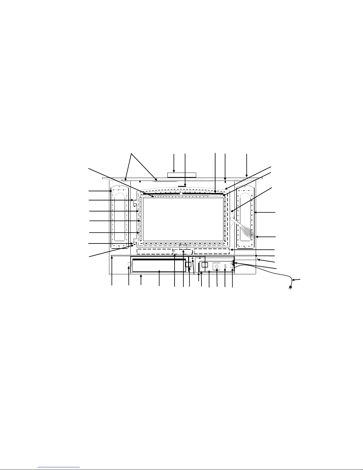
1. Secondary air tubes
2. Blower control (rheostat)
3. Primary air control
4. Warm air outlets
5. Baffles (interior of stove)
6. Air inlet
7. Cast Door
8. Hearth extension
9. Power cord
10. Disc thermostat
11. Motor guard screen
12. Automatic/off/man. switch
13.
Bottom secondary air channel
14. Hinge Block
(4)
(41)
(26)
(36)
(29)
(13)
15. Pipe stop
16. Outer top
17. Door glass
18. Glass clips
19. Hearth
20. Door gasket
21. Side glass
22. Side glass gasket
23. Firebrick
24. Motor
25. Motor mount bracket
26. Cover Door
27. Cover door screws
28. Shot gun air box
(15)
(17)
(28)
(27)
(34)
(25)
(24)
(39)
(11)
(2)
(5)
(12)
(16)
(21)
(35)
29. Ash pan
30. Bay side overlay
31. Door handle & spring handle
32. Top air wash
33. Cast door glass gasket
34. Cover door hinge
35. Magnet holder
36. Cover door Magnet
37. Door latch
38. Door latch screw
39. Top baffle board
40. Hinge pins
41. 8" Flue exit
42. Hinge cap
(7)
(32)
(37) & (38)
(30)
(31)
(23)
(19)
(3)
(10)
(9)
Page 4
Page 6
F
B
A
E
C
D
F
B
E
D
SECTION II
MASONRY INSERT INSTALLATION
The Model 94NC may be installed using an all masonry fireplace built in accordance with
Uniform Building Code and National Fire Protection Association (NFPA). The first step in
this type of installation is to determine acceptability of the fireplace and chimney for use with a
woodstove, both construction and condition of fireplace are important considerations when installing a woodstove. The chimney should extend at least 3' above roof and
at least 2' above any point of roof within 10'.
CAUTION
REMEMBER TO HAVE YOUR CHIMNEY INSPECTED FOR LEAKS AND BLOCKAGE
BEFORE YOU INSTALL YOUR STOVE. DO NOT CONNECT THIS UNIT TO A
CHIMNEY FLUE SERVING ANOTHER APPLIANCE.
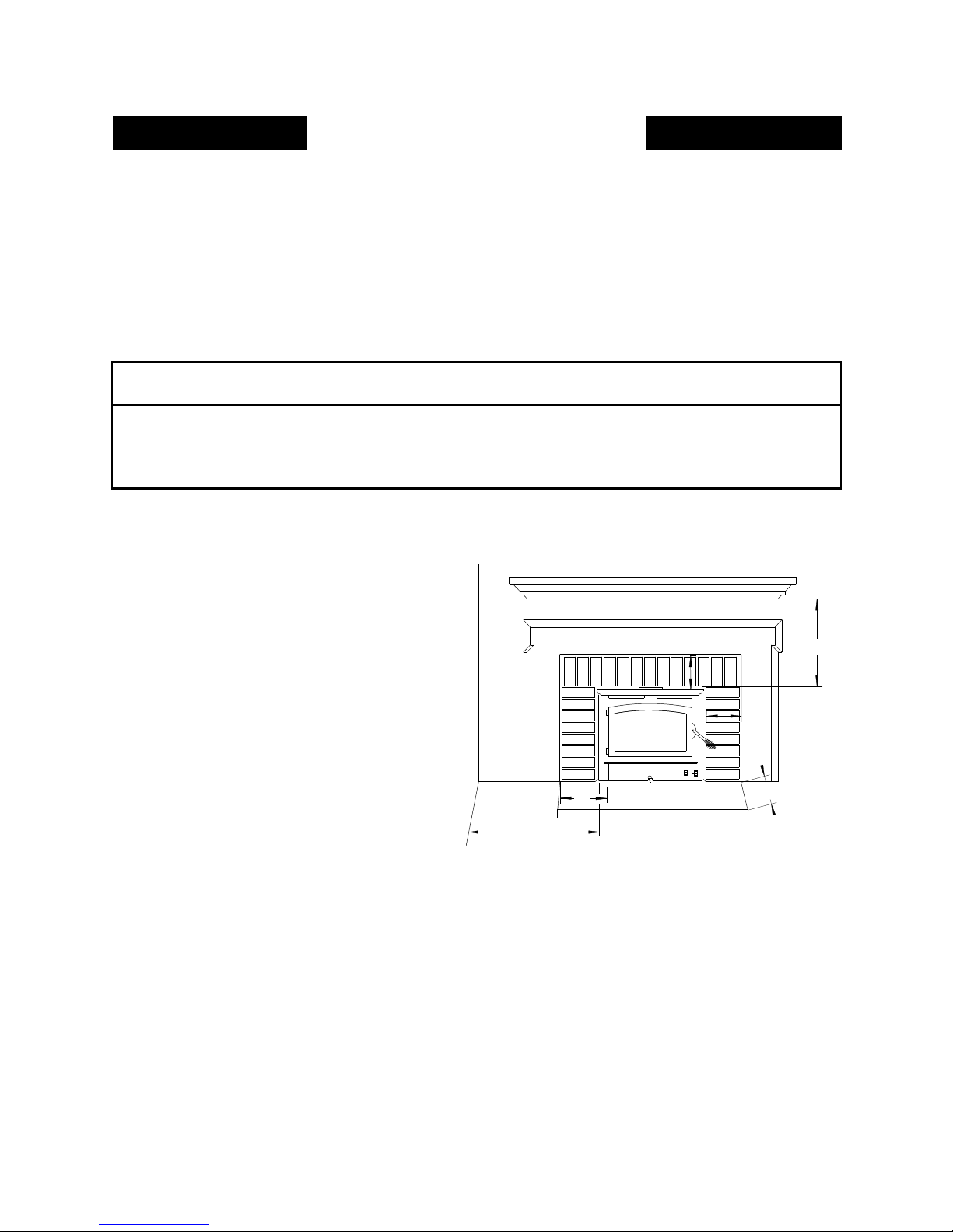
MINIMUM CLEARANCE MASONRY INSERT
MODEL 94NC
A. Side Wall Combustible
B. Front Floor Protector
C. Side Floor Protector
D. Side Wood Trim
E. Top Wood Trim
F. Mantel or Brackets
12"
16"
8"
10"
18"
24"
1. The hearth must be of masonry construction and must extend a minimum of 16" in front of
the firebox opening and a minimum of 8" to either side of the firebox opening.
Minimum floor protection under unit must have an R-value of 0.30.
2. If there is no minimum hearth protection from front of firebox opening and front of
masonry hearth, a floor protector must be used in front of hearth to protect combustible
materials. The floor protector must be 3/8" minimum thickness non-combustible material or
equivalent.(See Page 12,13).
Page 5
Page 7

POSSIBLE TOOLS NEEDED FOR INSTALLATION
If you decide to install your own stove, there are several hand tools you may need to do the job.
If you do not already have them they are readily available at most hardware stores.
Caulking gun
Large adjustable wrench (may not be needed)
Drop cloths or newspapers
Vacuum cleaner or whisk broom
Flashlight
1 tube of RTV silicone, Code 103 or 106, or high temperature rubber cement rated between
450o F- 600o F
7/32" drill bit and drill
Socket/Ratchet Set
INSTALLATION PREPARATION
Fireplace:
1. Relocate furniture and other materials away from front of fireplace to allow free access to
fireplace.
2. Cover hearth and adjacent floor areas with drop cloths to protect from soiling or marring
surface.
3. Remove existing fireplace damper plate.
4. Thoroughly clean fireplace of ashes and soot.
5. Check chimney and smoke chamber for excessive buildup of creosote or soot. Also, check
for obstructions, such as bird’s nests. If chimney is excessively dirty, clean it or have
someone clean it professionally BEFORE installing or using room heater.
6. If fireplace has an ash dump or outside air provision, these must be sealed off with metal or
tightly packed non-combustible insulation to prevent cold air from entering fireplace
chamber.
MASONRY INSERT INSTALLATION
INSTALLATION OPTIONS
This unit (appliance) may be installed into an all masonry fireplaces, built in accordance with
Uniform Building Code and National Fire Protection Association (NFPA 211).
NOTE: Check with local building officials for any permits required for installation of this unit
and notify your insurance company before proceeding with installation
It is imperative that your fireplace and oversize flue liner meets applicable codes. It is recommended that one of the flowing procedures be followed.
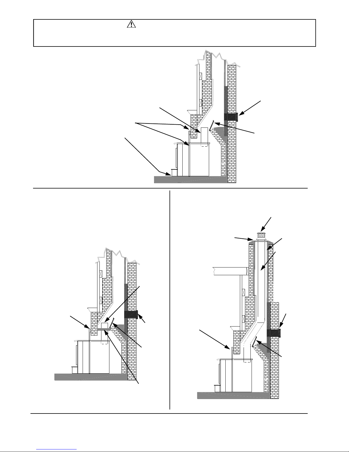
A. A Chimney Connector can be installed from appliance flue exit through damper with
an air-tight face seal. See option (A) Figure 2, page 7.
B. A listed Direct Connect can be installed from appliance flue exit through damper into
first section of flue liner with an air-tight seal. See option (B) Figure 3, page 7.
C. A Positive Connect can be installed from appliance flue exit continuing up through en-
tire chimney and exiting at top of the chimney. See option (C) Figure 4, page 7.
Page 6
Page 8
SAFETY NOTICE
If this appliance is not properly installed, a house fire may result. For your safety, follow the installation directions.
Contact local building or fire officials about restrictions and installation inspection requirements in your area.
OPTION (A) Figure 2,
AIRTIGHT INSU-
STARTER PIPE
SEAL TRIM PANELS AND UNDER
FRONT OF STOVE UNIT WITH
INSULATION OR HIGH
TEMPERATURE CAULK
NOTE: New Buck Corporation grants no warranty, implied or stated, for the installation or
maintenance of your appliance, and assumes no
responsibility of any consequential damage(s).
LATED CLEANOUT
REMOVE
DAMPER
OR WIRE
IT OPEN
OPTION (B) Figure 3,
NOTE: Follow installation instruction
with Direct Connection Kit.
(Kit sold separately)
SEAL TRIM PANELS
WITH INSULATION
OR HIGH
TEMPERATURE
CAULK
STAINLESS
STEEL
CHIMNEY
CONNECTOR MUST
EXTEND 1’
PAST THE
BLOCK-OFF
PLATE OR
TO THE
FLUE LINER
AIRTIGHT
INSULATED
CLEAN-OUT
REMOVE
DAMPER
OR WIRE IT
OPEN
OPTION (C) Figure 4,
NOTE: Follow installation
instruction with Positive
Connection Kit.
(Kit sold separately)
INSTALL A NON-COMBUSTIBLE
COVER PLATE TO PREVENT
WATER FROM ENTERING THE
CHIMNEY
TRIM PANELS
CAP(PREVENTS
WATER FROM
ENTERING)
FLUE
LINER
THE LINER MUST
BE STAINLESS
STEEL CONNECTOR OR FLEXIBLE
VENT. FOLLOW
THE LINER MANU-
FACTURER’S IN-
STRUCTIONS FOR
INSTALLATION
AND SUPPORT.
AIRTIGHT
INSULATED
CLEAN-OUT
REMOVE
DAMPER
OR WIRE
IT OPEN
BLOCK-OFF PLATE
OR DAMPER
ADAPTER
Page 7
Page 9
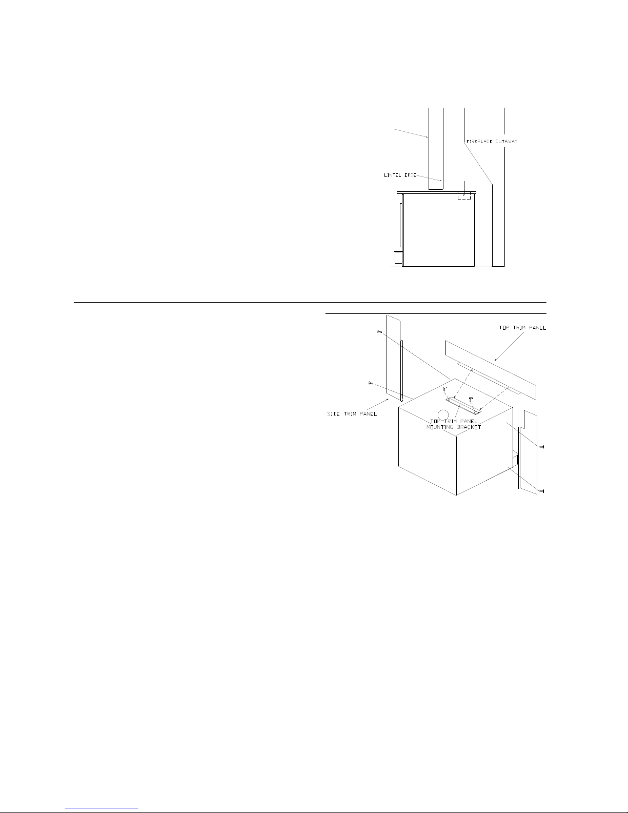
INSTALLATION PROCEDURE
(Use a chimney connector or a Listed Direct or Positive Connect) (See Page 6).
POSITIONING HEATER
FRONT OF FIREPLACE
When positioning heater, the following conditions
MUST be met. (See Figure 5).
1. The front of flue opening must be positioned
FLUE OPENING
BEHIND rear edge of the lintel to ensure proper
draft. (See Figure 5).
2. Center heater in fireplace opening.
FIGURE 5 POSITIONING
MOUNTING TRIM PANELS
NOTE: Mount top trim panel so that it sits in front of
top of side trim panels.
After unit is positioned, mark mounting position of trim
panels as follows:
1. Place side trim panels flat against face of fireplace.
Mark down front edge of trim panel with a pencil to
make a vertical reference line. (See Figure 6).
2. Set top (long) trim panel in place on top of unit.
The panel should be flat against the outside face
of fireplace, and standing vertically. Mark along
lower edge of trim panel with a pencil to make a
reference line for mounting.
3. Slide unit out of fireplace far enough to work
behind trim panel reference lines.
4. Mount side trim panels. (See Figure 6).
a. Position trim panel on reference line.
b. Drill mounting holes in center of trim panel mounting brackets to allow for adjustment in and out if neces-
sary.
c. Mount trim panel using self-tapping screws provided.
5. Place top panel back on reference mark. Take the top trim panel mounting bracket, position bracket so it overlaps rear lip of top trim panel. Drill mounting holes in top of stove using holes in bracket as guide. Tighten
down screws.
6. Now, follow installation procedures listed. Install heater and connect kit in fireplace. If not using one of
installation methods shown on (Page 7), then continue.
7. Slide unit back into fireplace. Check to be sure that trim panels are properly positioned so they lie flat against
front of fireplace. If one or more of panels is out of position, slide unit out and reset by loosening the
mounting screws and repositioning in the slot. Reinstall top trim panel by sliding rear lip of top trim panel
underneath front lip of mounting bracket.
FIGURE 6 MOUNTING TRIM PANELS
Page 8
Page 10
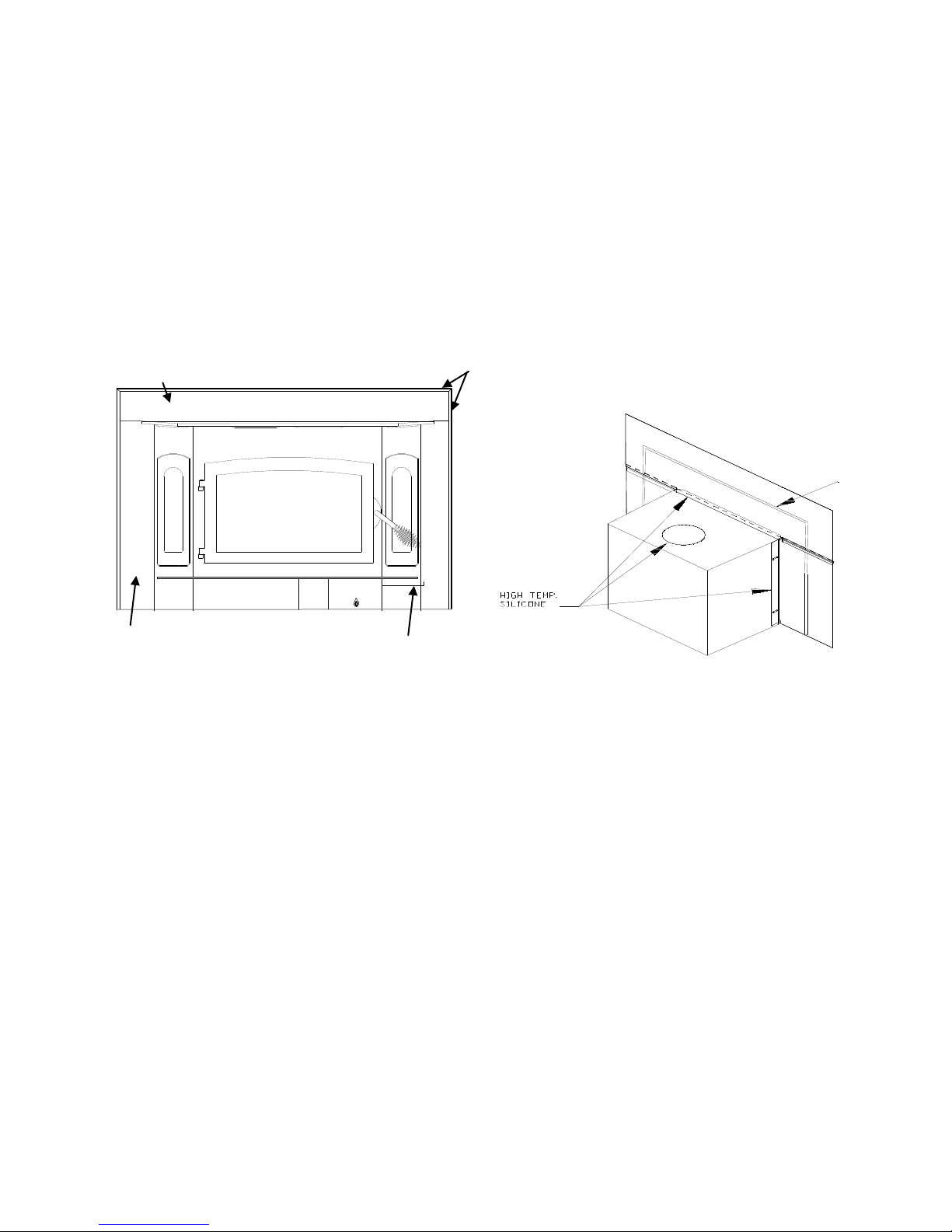
8. Obtain outer trim kit provided with insert kit. Slip it over top and sides of trim panels.(See Figure 7). (Top
DISCRIPTION
DATEREV.
BY
APRVD
ends of outer trim may need to be trimmed to fit).
9. Using insulation provided, peel and stick to back of panels. It will overlap fireplace dimensions by 1" on each
side and top. (See Figure 8).
10. Using high heat silicone or furnace cement run heavy bead of caulking around where back of panels meet
stove. (See Figure 8).
11. Slide unit back into fireplace. Check to be sure that trim panels (and outer trim) are properly positioned and
lie flat against front of fireplace. If panels are out of position, slide unit out and reset by loosening mounting
screws and repositioning in slot. Lift stove up in front by using the bar. Place insulation across the bottom and
surface of hearth, or bottom of fireplace, to make complete seal.
12. To check seal of panels, use candle flame and go around entire area sealed by silicone and insulation. If flame
leans toward inside of fireplace, add additional insulation. This ensures an airtight seal.
Top Trim Panel
FIGURE 7
Outer Trim
FIGURE 8
Side Trim Panel
Buck Stove
Primary Air Control
INSULATION
FINAL CHECK
1. Recheck specified clearances.
2. Remove all foreign material from firebox area.
3. Open primary air control. Primary Air Control: The primary air intake draft control is located at right bottom
side of hearth. It is operated by moving handle out to open (to allow air into firebox) or in (to control or
close off) to let air into firebox. (See Figure 7).
4. Plug power cord into a 115V AC outlet. Do not run cord under unit or in high traffic areas.
5. Place crumpled pieces of newspaper in stove. Light it and close door. Ensure that stove draws properly
through primary draft.
NOTE: Do not use grate or elevate fire. Build wood fire directly on fire box bottom.
6. Check for smoke leaks around door.
7. Open door and check for smoke escaping from front of stove. Smoking usually indicates a defective or poorly
positioned chimney. Some chimneys with a marginal draft can be pre-heated by lighting newspaper and
holding it near open damper. Once chimney heats up, a proper draft can usually be obtained.
If a thorough review of Troubleshooting Guide in rear of manual does not reveal
problem, contact your dealer for assistance.
Page 9
Page 11

THE UNIT IS PAINTED WITH A SPECIALLY FORMULATED HIGH
TEMPERATURE PAINT THAT CURES DURING THE FIRST TWO OR THREE
FIRES. YOU MAY NOTICE A SLIGHT SMOKING EFFECT AND AN ODOR OF
BURNING PAINT WHEN YOU BUILD THE FIRST FIRE. THIS IS NORMAL AND IS
NOT A CAUSE FOR ALARM. IN SOME CASES, THESE FUMES WILL ACTIVATE
A SMOKE ALARM. OPENING A WINDOW NEAR THE UNIT WILL ALLOW
THESE FUMES TO ESCAPE. DO NOT BUILD A LARGE, ROARING FIRE UNTIL
THIS CURING IS COMPLETE OR THE HEATER FINISH MAY BE DAMAGED.
CAUTION
The connector and/or chimney should be inspected at least once a month during the heating
season to determine if a creosote build up has occurred.
CAUTION
NEVER USE GASOLINE, GASOLINE-TYPE LANTERN FUEL, KEROSENE,
CHARCOAL LIGHTER FLUID OR SIMILAR LIQUIDS TO START OR "FRESHEN
UP" A FIRE. KEEP ALL SUCH LIQUIDS WELL AWAY FROM THE STOVE WHEN
IT IS IN USE. ALL FLUIDS OF THIS TYPE GIVE OFF VOLATILE FUMES AND
CAN AND WILL EXPLODE!! DON'T TAKE A CHANCE WITH THE SAFETY OF
YOUR HOME AND FAMILY.
Page 10
Page 12
SECTION IV
RESIDENTIAL FREESTANDING
INSTALLATION
Select an installation location that will give best airflow from front of heater to
remainder of home.
PREPARING STOVE FOR INSTALLATION
1. Inspect unit for any obvious physical damage.
2. Plug power cord into a 115V AC outlet to test motor. Do not run power cord under unit or
in high traffic areas.
3. Check primary air and control to ensure that it slides freely.
4. Remove any items from within firebox. Spread a dropcloth on floor behind heater. Next, tilt
heater so that back is on drop cloth.
5. If leg kit is to be used follow steps 1-4.
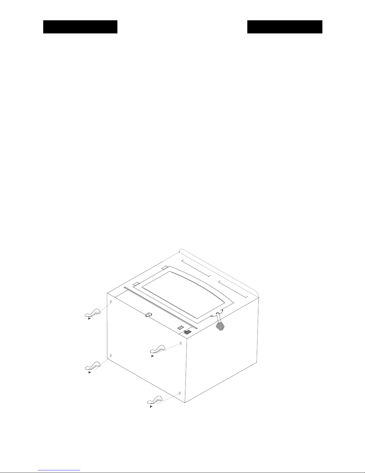
6. Obtain four legs, attach legs to holes in bottom of unit with bolts and washers. (See Figure
9).
7. Reposition heater to upright position.
Figure 9
Page 11
Page 13

Chimney
This model is designed for connection to any listed 2100º UL103 HT chimneys and parts.
Follow chimneys manufacturer's instructions carefully.
This room heater must be converted to (1) a chimney complying with the requirements for
Type HT chimneys in the Standard for chimneys, Factory-Built, Residential, Type and
Building Heating Appliance, UL 103, or (2) a code approved masonry chimney with a flue
liner. The chimney size should not be less than or more than three times greater the crosssectional area of the flue collar.
Floor Protection:
Floor protection must be 3/8” minimum thickness non-combustible material or equivalent, and
have an R-value of 0.30.
How to use alternate materials and how to calculate equivalent thickness
An easy means of determining if a proposed alternate floor protector meets requirements is to
follow this procedure:
1. Convert specification to R-value:
R-value is given—no conversion is needed.
K-factor is given with a required thickness (T) in inches:
C-factor is given: R=1/C
2. Determine the R-value of the proposed alternate floor protector.
Use the formula in step (1) to convert values not expressed as “R”
For multiple layers, add R-values of each layer to determine the overall R-value.
3. If the overall R-value of the system is greater than the R-value of the specified floor
protector, the alternate is acceptable.
Example:
The specified floor protector should be 3/4” thick material with a K-factor of 0.84.
The proposed alternate is 4” brick with a C-factor of 1.25 over 1/8” mineral board with a
K-factor of 0.29.
Step (a): Use formula above to convert specification to R-value. R= 1/K x T = 1/0.84 x .75 =
0.893
(Continued on next page)
Page 12
Page 14
Step (b): Calculate R of proposed system. 4” brick of C=1.25, therefore Rbrick = 1/C = 1/1.25
=0.80 1/8” mineral board of K = 0.29, therefore Rmin.bd. =1/029 x0.125 = 0.431
Step (c): Compare proposed system R of 1.231 to specified R of 0.893. Since proposed
system R is greater than required , the system is acceptable.
Definitions:
Thermal conductance = C =
Btu
(hr)(ft²)(°F) (m²)(°K)
=
W
Thermal conductance = K =
(Btu)(inch)
(hr)(ft²)(°F) (m)(°K) (hr)(ft)(°F)
=
W
=
(Btu)
Thermal conductance = R =
(ft²)(hr)(°F)
Btu W
(m²)(°K)
=
Install in accordance with 24 CFR, Part 3280 (HUD).
SPECIAL METHODS ARE REQUIRED WHEN PASSING THROUGH A
WALL OR CEILING. SEE INSTRUCTIONS AND BUILDING CODES.
“DO NOT CONNECT THIS UNIT TO A CHIMNEY FLUE SERVING
ANOTHER APPLIANCE.
CAUTION
DETERMINING CHIMNEY LOCATION
A. CEILING EXIT ( Using 8” inch Diameter Residential Single Wall (minimum 24-ga.)
Black Chimney Connector and any listed 2100 UL 103 HT type Chimney System ).
(See Page 14).
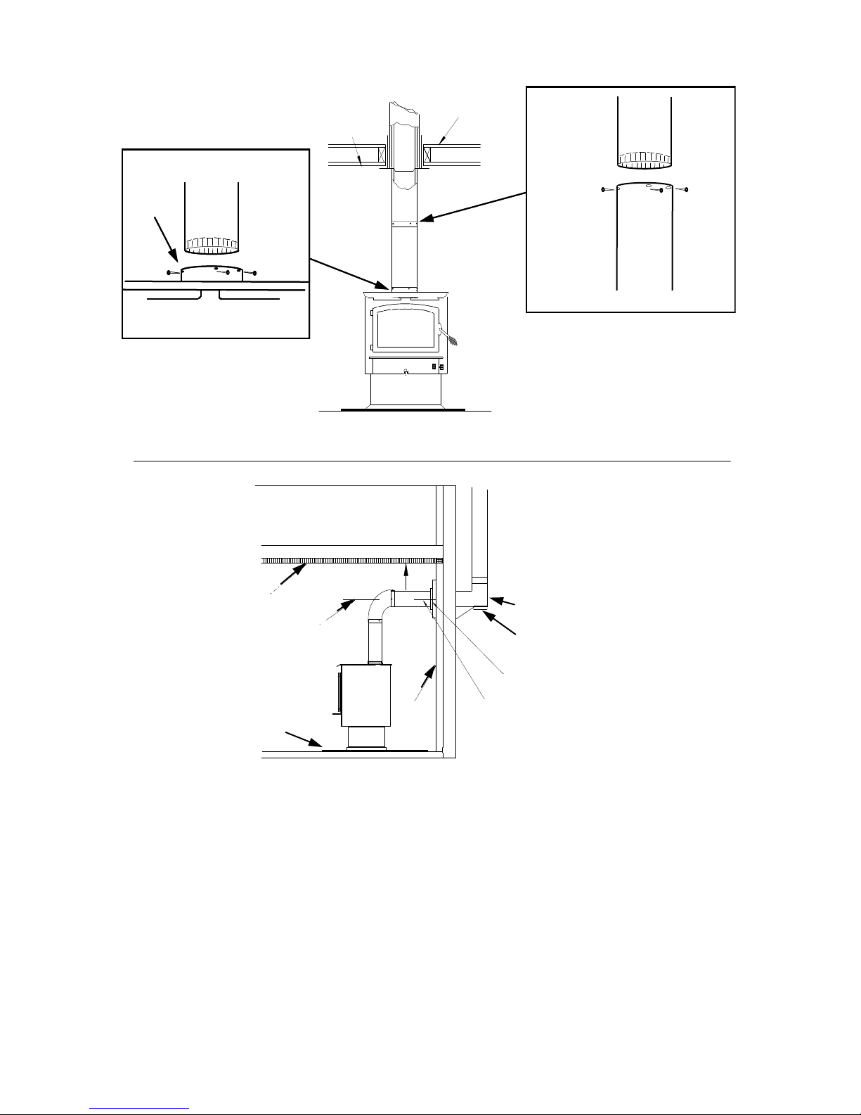
1. Suspend a plumb bob from ceiling above unit so that weight is hanging in center of flue
exit, (a small weight on a string will serve as a plumb bob). Mark ceiling where string is
suspended to locate center of chimney.
2. After locating center of hole, install ceiling support box, chimney flashing and rain cap
per chimney manufacturer’s instructions.
Now connect stove and ceiling support box using #24 ga. minimum blue or black steel
connector pipe (DO NOT USE GALVANIZED PIPE). Connect each section so crimped
end faces downward, and secure each section to each other using at least three (3) sheet metal
screws or rivets. Also use three (3) sheet metal screws to fasten pipe to collar on heater. (See
Figure 10. Page 15).
Page 13
Page 15
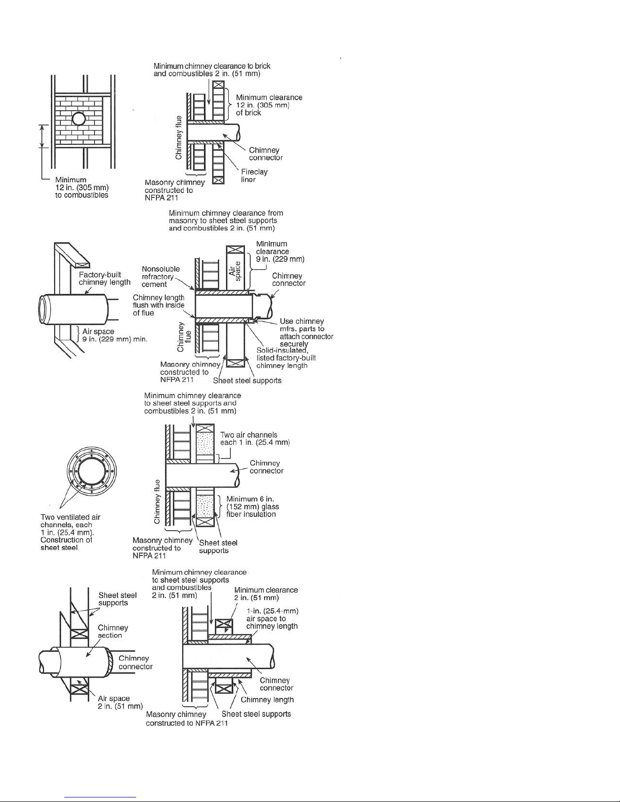
Installing a thimble through combustible wall
Chimney Connector Systems and Clearances from Combustible Walls for Residential Heating Appliances
a) Minimum 3.5-in thick brick masonry all framed into
combustible wall with a minimum of 12-in brick
separation from clay liner to combustibles. The
fireclay liner shall run from outer surface of brick wall
to, but not beyond , the inner surface of chimney flue
liner and shall be firmly cemented in place.
b) Solid-insulated factory-built chimney length of the
same inside diameter as chimney connector and
having 1-in. or more of insulation with a minimum 9-in.
air space between outer wall of chimney length and
combustibles.
c) Sheet steel chimney connector, minimum 24 gauge in
thickness, with a ventilated thimble, minimum 24
gauge in thickness, having two 1-in. air channels,
separated from combustibles. by a minimum of 6-in. of
fiber insulation. Opening shall be covered, and thimble
supported with a sheet steel support, minimum 24
gauge in thickness.
d) Solid insulated, listed factory-built chimney length with
an inside diameter 2-in. larger than chimney
connector and having 1-in. or more of insulation,
serving as a pass-through for a single wall sheet steel
chimney connector of minimum 24 gauge thickness,
with a minimum 2-in. air space between outer wall of
chimney section and combustibles. Minimum length of
chimney section shall be 12-in. chimney section
spaced 1-in. away from connector using sheet steel
support plates on both ends of chimney section.
Opening shall be covered, and chimney section
supported on both sides with sheet steel supports
securely fastened to wall surface of minimum 24
gauge thickness. Fasteners used to secure chimney
Page 14
section shall not penetrate chimney flue liner.
Page 16
CEILING
ROOF
ATTIC
CEILING
"TEE" BOX ASSEM.
CENTER LINE
OF ELBOW
MARK PLUMB LINE
WALL
WALL PASS-THROUGH CONNECTOR
18" MIN.
CEILING
ROOF
COLLAR
COLLAR
3 SHEET METAL SCREWS
3 SHEET METAL SCREWS
3 SHEET METAL SCREWS OR RIVETS
FLOOR PROTECTOR
B. Wall Exit Into Metal Tee-Box
Figure 5
Figure 10
Figure 11
TEE BOX ASSEM.
CLEAN OUT ACCESS
1. Mark plumb line on wall directly behind center of heater. (See Figure 11).
NOTE: When using 24# ga. minimum blue or black steel pipe, maintain 18" between
pipe and ceiling.
NOTE: Floor protector must be under horizontal pipe exit (See Figure 13. Page 19).
2. Place vertical portion of heater pipe and elbow in position and project a point onto plumb
line level, using the center of your elbow.
Page 15
Page 17

3. Measure up so there will be at least 1/4" rise per foot of horizontal connector pipe,
maintaining clearances to ceiling as noted in Figure 12. This will give you center hole for
chimney penetration.
4. After locating center of penetration, install tee-box and chimney,as per chimney
manufacturer's specifications.
5. Connect chimney connector to tee-box using #24 ga. minimum blue or black steel connector
pipe. DO NOT use galvanized pipe. Connect each section so the crimped end faces
downward, and secure each section to each other using three (3) sheet metal screws or
rivets. (See Figure 10. Page 15).
C. Wall Exit Into Masonry Flue (Using Single Wall Pipe)
1. Before connecting these units to a masonry chimney, determine that masonry flue passing
through connector thimble meets NFPA-211 Code and local building codes. It must be
a minimum of 18" from ceiling. If connector thimble does not meet these codes, passthrough connector must be modified.
NOTE: Floor protector must be under horizontal pipe exit (See Figure 13. Page 19).
CEILING CENTER LINE
OF ELBOW
SECURE WITH (3)
SHEET METAL SCREWS
FLOOR PROTECTOR
See Figure 13. Page 17.
1/4” RISE PER FT’
MARK PLUM LINE
SEAL AROUND PIPE TO
THIMBLE OR PASSTHROUGH CONNECTOR
WITH NON-COMBUSTIBLE
MATERIAL
WALL
Figure 12
MASONRY
FLUE
LINERS
CLEAN OUT
DOOR
MASONRY CHIMNEY
Page 16
Page 18

Connectors may pass through walls or partitions constructed of combustible material if
connector is:
(a) Either listed for wall pass-through or is routed through a device listed for wall pass-
through. It must be installed in accordance with conditions of listing.
(b) Selected or fabricated in accordance with conditions and clearances as stated
in NFPA-211 Code. Any unexposed metal that is used as part of a wall pass-through
system and is exposed to flue gases shall be constructed of stainless steel or other
equivalent material.
In addition, a connector to a masonry chimney shall extend through wall to the inner face or
liner but not beyond, and shall be firmly cemented to masonry.
EXCEPTION: A thimble may be used to facilitate removal of the chimney connector for
cleaning, in which case the thimble shall be permanently cemented in place
with high-temperature cement.
2. Once through-the-wall thimble codes are met, simply connect chimney collar to wall pass
through connector using #24 ga. minimum, blue or black steel connector pipe as follows:
(a) Maintain 1/4" rise per foot (horizontal length) from appliance to chimney.
(b) Connect each section so crimped end faces downward.
(c) Secure each section to each other using at least three (3) sheet metal screws or rivets
(See Figure 10. Page 15).
(d) Use three (3) sheet metal screws to fasten pipe to connector collar on heater.
(See Figure 10. Page 15).
Page 17
Page 19

FINAL CHECK
1. Recheck specified clearances.
2. Remove all foreign material from firebox area.
3. Open primary air control. Primary Air Controls: The primary air intake control is located
at right bottom side of hearth. It is operated by moving the handle out to open (to allow air
into the firebox) or in to control or close off the firebox.
4. Plug power cord into a 115V AC outlet to see if motor and blower works. Do not run power
cord under unit or in high traffic areas.
5. Place crumpled pieces of newspaper in stove. Light it and close door. Ensure that
stove draws properly through primary draft.
6. Check for smoke leaks around door.
Open door and check for smoke escaping from front of the stove. Smoking usually
indicates a defective or poorly positioned chimney. Some chimneys with a marginal draft
can be preheated by lighting newspaper and holding it near open damper with a poker or
fire tong. Once chimney heats up, a proper draft can usually be obtained.
If review of Troubleshooting Guide does not reveal problem, contact your dealer for assistance.
CAUTION
The unit is painted with a specially formulated high temperature paint that cures during
the first two or three firings. You may notice a slight smoking effect and an odor of
burning paint when you build the first fire. This is normal and is not a cause for alarm. In
some cases, these fumes will activate a smoke alarm. Opening a window near unit will
allow these fumes to escape. DO NOT build a large, roaring fire until this curing
is complete or heater finish may be damaged.
CAUTION
Page 18
Page 20
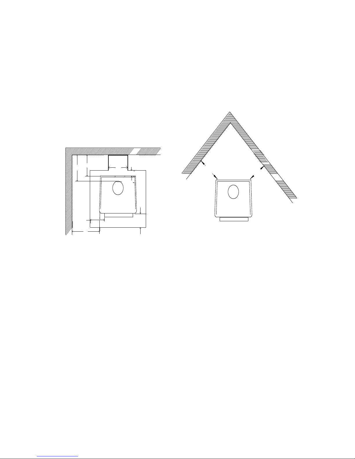
CLEARANCES FOR MODEL 94NC
BACK WALL
SIDE WALL
A
E
B
F
C
C
D
G
MINIMUM CLEARANCES TO COMBUSTIBLES
RESIDENTIAL SINGLE WALL CONNECTOR
C
E
A
B
F
C
H
G
D
D
Figure 13
A B C D E F G H
MODEL 94NC 25" 8" 10.5" 8" 8" 6" 20" 10”
22” 23” 26” 23” 8” 6” 16” 12”
NOTE: All clearances are combustibles using single wall pipe, minimum floor protector.
Minimum floor protection under unit must have an R-value of 0.30. (see page 12, 13)
NOTE: The clearances above may be reduced, follow NFPA-211 codes.
For wall exit, floor protector must be under horizontal pipe. There must be 2” on each
side of pipe. Maintain 18" between pipe and ceiling.
(See Figure 13, measurements F & H ).
Page 19
Page 21
SECTION VI
WOOD HEATER SAFETY
Certain safety hazards are inherent in any wood heater installation. You should be aware of
these so that a safe and proper installation can be made.
1. FAULTY CHIMNEY: An older masonary chimney should be thoroughly checked to be
sure there are no holes or weak spots, which could allow sparks or hot gases to escape.
2. HEAT CONDUCTION: Placing combustible materials too close to a heater or chimney can
be a fire hazard.
By keeping these particular hazards in mind as you install and use your room heater you can
ensure a safe, reliable installation.
The chimney and chimney connector should be inspected once every two months. Any buildup of soot should be removed to prevent the risk of a chimney fire. To remove chimney or
chimney connector, remove screws or fasteners. Remove pipe and clean with steel brush.
Replace chimney or chimney connector, and replace screws and/or fasteners.
NEVER USE GASOLINE, GASOLINE TYPE LANTERN FUEL, KEROSENE,
CHARCOAL LIGHTER FLUID OR SIMILAR LIQUIDS TO START OR "FRESHEN
UP" A FIRE IN THE HEATER. KEEP ALL SUCH LIQUIDS WELL AWAY FROM
THE STOVE WHEN IT IS IN USE. ALL FLUIDS OF THIS TYPE GIVE OFF
VOLATILE FUMES AND CAN AND WILL EXPLODE!! DON'T TAKE A CHANCE
WITH THE SAFETY OF YOUR HOME AND FAMILY.
CAUTION: Never remove ashes from heater with blower running.
DISPOSAL OF ASHES: Ashes should be placed in a metal container with a tight fitting lid.
The closed container of ashes should be placed on a non-combustible floor or on the ground,
well away from all combustible materials pending final disposal. If ashes are disposed of by
burial in soil or otherwise locally dispersed, they should be retained in closed container until all
cinders have thoroughly cooled.
CREOSOTE-FORMATION AND NEED FOR REMOVAL: When wood is burned slowly,
it produces tar and other organic vapors, which combine with expelled moisture to form
creosote. The creosote vapors condense in the relatively cool chimney flue of a slow-burning
fire. As a result, creosote residue accumulates on the flue lining. When ignited this creosote
makes an extremely hot fire.
CAUTION
Page 20
Page 22

SECTION VII OPERATION
This section of the manual is to help you get maximum efficiency and maximum smoke
(particulate) reduction from your heater. If you should experience any difficulty or have any
questions concerning your heater, contact your dealer for assistance. NOTE: The
manufacturer recommends that for maximum performance burn natural seasoned
hard wood.
Build a fire for maximum efficiency. This model burns wood and extracts heat so efficiently,
a large fire is not necessary. A large fire not only wastes energy, it usually results in home
being too warm for comfort.
The following steps will serve as a guide for operating your stove.
BUILDING A FIRE
1. Open door.
2. Open primary air control. Primary Air Controls: The primary air intake draft control is
located at right bottom side of hearth. It is operated by moving handle out to open (to
allow air into firebox) or in (to control or close off) to let air into firebox.
3. Twist two pieces of non-colored newspaper into a roll and place them on floor of firebox.
NOTE: Do not use grate or elevate fire. Build wood fire directly on inner bottom of fire box.
4. This model is not designed for use of grates, andirons or other methods of supporting fuel.
5. Lay several pieces of dry kindling on top of newspaper.
6. Place three or four small pieces of firewood, 2"-3" in diameter, on top of kindling.
7. Light newspaper in front. Close and latch door. Don't leave fire unattended at this point.
The draft system of heater should start quickly. It may be necessary to preheat chimney
to get draft started. To do this, open door and add newspaper to top rear of wood. Light
or let this paper ignite and allow to burn while holding the door slightly cracked. Once
draft has started, close and lock door. You are over- heating the unit if the chimney and or
connector glows red.
8. NOTE: After embers and a coal bed have been established, load heater with seasoned
natural hard wood, placing it front to rear.
NOTE: THE FUELING DOOR MUST REMAIN CLOSED DURING OPERATION.
BURN RATE: LOW MED-LOW MED-HI HI
AIR SETTINGS: 1/32” 5/32” 9/32” WIDE OPEN
Your stove is equipped with an automatic thermostat. When stove gets hot enough,
thermostat will activate room air blower. Set fan speed on low, when burning on low,
med-low or med-high. Set fan speed on high when burning on high.
NOTE: When refueling or removing ashes turn “OFF” room air blower. Be sure to turn
room air blower back on when finished.
NOTE: Do not run power cord underneath heater or in walk way or heavy traffic areas.
Page 21
Page 23
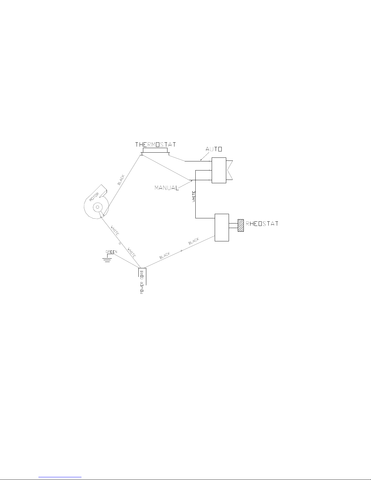
ROOM AIR BLOWER OPERATION
Your heater is equipped with a room air blower. For operation and wiring see figure 14.
For your convenience your heater is equipped with a rheostat with which you are able to select
air flow. The auto and manual switch will allow you to select the position at which thermostat
will function.
Auto-position: After heater has warmed up and Auto-Manual switch is placed in “Auto”
position and rheostat is in desired position, the fan will automatically come on. When stove
cools off fan will automatically shut-off.
Manual position: You must turn room air blower on and off.
NOTE: Plug power cord into a 115V AC outlet. Set switch to “Manual” and rheostat to
“High” position to ensure motor operates properly. Route cord to prevent damage to
cord insulation from heat and sharp objects. Keep cord out of the way of traffic to
prevent damage caused by tripping, etc.
Figure 14
Page 22
Page 24

SECTION VIII
TROUBLESHOOTING
PROBLEM POSSIBLE CAUSE SOLUTION
Sluggish Heater Obstruction in chimney Check for and remove
obstruction
Improperly sealed trim kit or
direct connect kit
Manual damper in chimney is
closed
Wet or unseasoned wood
being burned
Poor chimney draft Improper chimney height or
Improper wood loading Load wood from front to rear
(a) Check trim kit gasketing
seal to fireplace and
gasket as necessary to
seal unit. Gasket under
front bottom of stove if
needed.
(b) Check seal if using direct
connect and correct.
Open manual damper and
wire shut with stainless steel
wire or remove damper
Burn dry, natural seasoned
hard wood
wrong size flue is being used.
Cooler temperatures caused
by external chimney
Page 23
Page 25

TROUBLESHOOTING
(Continued)
PROBLEM POSSIBLE CAUSE SOLUTION
High fuel consumption Improper regulation of draft
or inlet air
(a) Close inlet air control as
much as possible to
maintain desired heat
output
(b) Check gaskets, reinstall
fiberglass gasketing
round doors and glass as
necessary
Improper door fitting Check door gasket, check
adjustment of door latch
Backpuffing Gusts of Wind (a) Smoke shelf in chimney
is filled with creosote &
ash
(b) Chimney may need wind
diverter. Raise chimney
for better draft
Smoke rollout when heater
door is opened
Wind gusts blowing down the
chimney
(a) Smoke shelf in chimney
is filled with creosote &
ash
(b) Chimney may need wind
diverter. Raise chimney
for better draft
Opening heater door too fast Crack door for 15 seconds
before fully opening door
Page 24
Page 26

REPLACEMENT PARTS
FOR MODEL 94NC
Description Part Number
1. Primary Air Handle PS 94NC040
2. Door Handle Assembly PA 910096
3. Door Latch PC 910098
4. Door Handle Washer PO 91WASH
5. Front Door Bushing PO 910102
6. Door PC 912651
7. Carling Fan Auto/Man Switch PE RC211RB
8. Thermostat 110° Disc PE 400132
9. Power Cord PE 400240
10. Strain Relief PE 400320
11. Motor PE 910714
12. Rheostat PE BC204
13. Rheostat Knob PE BC204A
14. Glass PG 265191GL
15. Glass (Bay Side) PG 27BSGL
16. Bay Glass Overlay PO 910454G
17. Glass Clip PO 912651
18. Glass Clip Screws PH 103212HWSPS5
19. Spring Handle PO 100150B
20. “U” Drive Screw (5/16” x 1/2”) PO 516U
21. Front Secondary Air Tube PO 94NC010
22. Rear Secondary Air Tube PO 94NC012
23. Primary Shotgun & Air Block MF 910080
24. Top Baffle Board PO BPFB94
25. 1” x 1” x 1/8” Thick Magnet PO DM841
26. Firebrick PR 900050
27. Motor Guard Screen PS 910105
Page 25
Page 27

NEW BUCK CORPORATION (NBC)
"LIMITED WARRANTY" FOR THE BUCK STOVE
PLEASE READ THIS WARRANTY CAREFULLY
PRODUCTS COVERED
This warranty covers the new Buck Stove heating unit, so as long as it is owned by the original
purchaser, including optional and standard accessories purchased at the same time, subject to
terms, limitations, and conditions set out herein .
PRODUCTS NOT COVERED
This warranty does not cover the following:
Glass, Refractory Material, Firebrick or Gaskets.
This Warranty will not cover any damage and/or failure caused by abuse or improper installation
of the products covered.
WARRANTY TIME PERIODS
(A) Period I
For one year from the date of purchase, NBC will replace or repair, at its option, any
part defective in materials or workmanship. The costs of parts are included. The customer
pays any labor or transportation charges required.
(B) Period II
For the period after the first year from the date of purchase and extending for five years as
long as the Buck Stove is owned by the original purchaser, NBC will repair or replace at
its option, any part defect in materials or workmanship with the exception of: electrical
motors, wiring, switches, components, optional standard accessories, and all parts not
permanently attached to the heating unit. Parts not permanently attached to the heating
unit are defined as those items designed to be removed from the stove, including those
removable with common hand tools. The costs of parts only are included. The customer
pays any labor or transportation charges required.
.
PROCEDURE
Should you feel that your BUCK STOVE is defective, you should contact any Buck Stove
dealer for the name of your nearest authorized Buck Stove service representative, who will
instruct you on the proper procedure, depending on which Warranty Time Period (Period I or
Period II) applies.
Page 26
Page 28

If for any reason you are dissatisfied with the suggested procedures, you may contact us
in writing at:
New Buck Corporation
Customer Service Department
P. O. Box 69
Spruce Pine, NC 28777
Email: [email protected]
CONDITIONS AND EXCLUSIONS
(A) Replacement of parts may be in the form of new or fully reconditioned parts, at NBC's option.
(B) There is no other express warranty. All implied warranties of merchantability and fitness for use are
limited to the duration of the Express Warranty.
(C) New Buck Corporation is not liable for indirect, incidental, or consequential damages in
connection with the use of the product including any cost or expense of providing substitute
equipment or service during per iods of malfunction or non -use.
Some states do not allow the exclusion of incidental or consequential damages, so the
above exclusion may not apply to you.
(D) All warranty repairs under this warranty must be performed by an authorized Buck Stove service
representative. Repairs or attempted repairs by anyone other than an authorized service representative are not covered under this warranty. In addition, these unauthorized repairs may result in
additional malfunctions, the correction of which is not covered by warranty.
OTHER RIGHTS
This warranty gives you specific legal rights. You may also have other rights which vary from state to
state.
OWNER REGISTRATION CARD
The attached Owner Registration Card must be completed in its entirety and mailed within 30 days from
the date of purchase or from the date of installation, if installed by a factory certified installer, to New
Buck Corporation in order for warranty coverage to begin.
PLEASE NOTE: The Owner Registration Card must contain the Authorized Buck Stove Dealer Code
Number and the Certified Installer's number (if applicable) for warranty coverage to begin.
To be completed by selling distributor/dealer/ customer:
Name ________________________________________________________________________
(Last) (First)
Address ______________________________________________________________________
City _______________________________________ State ________ Zip _________________
CUSTOMER EMAIL:_________________________________________________________
MODEL NC94 - Serial Number ___________________________________________________
Date of Installation: Day ________________ Month ________________ Year ______________
Installer’s Name ________________________________________________________________
Installer’s Certification Number ___________________________________________________
Dealer’s Name _________________________________________________________________
City _______________________________________ State ________ Zip _________________
 Loading...