


94NC
MODEL 94NC
DISCRIPTION
DATEREV.
BY
APRVD
NON-CATALYTIC UNIT
Buck Stove
FIREPLACE INSERT & FREESTANDING
FEATURES
PREPARATIONS INSTALLATION
OPERATION MAINTENANCE SAFETY
SAFETY NOTICE
IF THIS HEATER IS NOT PROPERLY INSTALLED, A HOUSE FIRE MAY
RESULT. FOR YOUR SAFETY, FOLLOW THE INSTALLATION INSTRUCTIONS.
CONTACT THE AUTHORITY HAVING JURISDICTION (SUCH AS MUNICIPAL
BUILDING DEPARTMENT, FIRE DEPARTMENT, FIRE PREVENTION BUREAU,
etc.) CONSULT BEFORE INSTALLATION TO DETERMINE THE NEED TO
OBTAIN A PERMIT. KEEP THESE INSTRUCTIONS FOR FUTURE USE.
TESTED AND LISTED BY: ITS/WARNOCK HERSEY, MIDDLETON, WI
MANUFACTURED BY NEW BUCK CORPORATION
200 ETHAN ALLEN DRIVE
P.O. BOX 69
SPRUCE PINE, N.C. 28777
www.buckstove.com
Revised January 2013

TABLE OF CONTENTS
Important Instructions ............................................................................. 2
SECTION I: Introduction ....................................................................... 3
Type of wood and loading procedures ................................................... 3
Parts List .................................................................................................. 4
SECTION II: Masonry Insert Installation .............................................. 5
Installation Preparation-Fireplace ........................................................... 6
Mounting Trim Panels ............................................................................. 7
SECTION III: Residential Freestanding Installation ............................ 11
Floor Protection ..................................................................................... 12
Installing thimble through combustible wall ....................................... 14
Final Check ........................................................................................... 18
Clearances: Residential / Single Wall Pipe ........................................... 19
SECTION IV: Wood Heater Safety ...................................................... 20
SECTION VI: Operation ...................................................................... 21
Room Air Blower Operation ................................................................. 22
SECTION VII: Troubleshooting ........................................................... 23
Warranty ................................................................................................ 26

INSTALLATION, OPERATION, AND
MAINTENANCE INSTRUCTIONS
MODEL 94NC
BEFORE INSTALLING YOUR NEW BUCK STOVE,
READ THE ENTIRE INSTRUCTION MANUAL
IMPORTANT INSTRUCTIONS
THIS UNIT GENERATES HIGH HEAT, SO TREAT IT WITH CARE. HOT WHILE
IN OPERATION . KEEP CHILDREN, CLOTHING AND FURNITURE AWAY.
CONTACT MAY CAUSE SKIN BURNS. DO NOT USE CHEMICALS OR FLUIDS TO
START THE FIRE. DO NOT BURN GARBAGE OR FLAMMABLE FLUIDS. DO NOT
CONNECT TO ANY DISTRIBUTION DUCT OR SYSTEM. READ ALL
INSTRUCTIONS BEFORE INSTALLING AND USING THE APPLIANCE. FAILURE
TO FOLLOW INSTRUCTIONS MAY RESULT IN PROPERTY DAMAGE, BODILY
INJURY OR EVEN DEATH. AVE THESE INSTRUCTIONS FOR FUTURE
REFERENCES.
The New Buck Corp. non-catalytic Model 94NC has been tested and listed by ITS,
(Warnock Hersey) to ANSI/UL Standards, :UL1482(2000) :UL1482(2006) :UL1482
(2010) Standard for Room Heaters, Solid Fuel Type.
WARNING
Install and operate your unit according to instructions provided in this manual. Local
building codes may apply; therefore, contact your local building inspector or fire marshal
for necessary installation requirements and permits which may go beyond these
instructions. Contact your insurance company for coverage and installation inspection.
DO NOT INSTALL IN SLEEPING ROOMS.
NOTE: When burning any unit or appliance that combusts fuel for heat, such as
coal, oil, wood or natural and (L.P.) liquid petroleum gas, we highly recommend the
use of smoke and carbon monoxide detectors in your home.
Examine the masonry fireplace and chimney prior to installation of fireplace accessory to
determine that construction meets the minimum fireplace construction requirements
illustrated in the instructions. Make sure that it is free from cracks, loose mortar, creosote
deposits and other blockage, or other signs of deterioration.
CAUTION
DO NOT USE MORE THAN ONE STOVE PER CHIMNEY. DO NOT USE A FLUE
INTENDED FOR A GAS APPLIANCE.
Page 2

CAUTION
YOUR CHIMNEY OR FLUE MUST BE CORRECTLY SIZED. A CHIMNEY OR FLUE
THAT IS TOO SMALL OR LARGE IN DIAMETER OR TOO SHORT CAN CAUSE YOUR
STOVE TO SPILL SMOKE WHEN THE DOOR IS OPENED.
SECTION I
INTRODUCTION
The MODEL 94NC is a non-catalytic unit designed to meet the most stringent emissions
standards without use of a catalytic combustor. This effect is achieved through use of
secondary air which is mixed with primary air in firebox.
For peak performance, we suggest the use of natural seasoned hard wood. Load wood
from front to rear.
NOTE: Soft woods such as pine, create more creosote, clogging of chimney and produce a less
efficient burn performance.
You should not burn trash or garbage, artificial or paper logs, gift wrapping, treated or
painted wood, or any type of coal or flammable fluids.
The primary air, which is controlled by user, burns the wood. Secondary air is admitted into
firebox through secondary air tubes at top of firebox. This secondary air burns impurities in
the smoke released from initial wood burning. The temperature necessary for this combustion
is maintained through firebrick refractory. If any more technical information is necessary,
contact your local dealer.
Under specific test conditions this heater has been shown to deliver heat at rates ranging from
approximately :
11,900 BTU/HR. on Low
42,100 BTU/HR. on High
This unit is equipped with a standard room air blower.
Page 3
EPA COMPLIANCE STATUS
DISCRIPTION
DATEREV.
BY
APRVD
DISCRIPTION
DATEREV.
BY
APRVD
The Model 94NC heater meets U.S. Environmental Protection Agency’s Emission limits for non cat wood heaters sold after July 1, 1992. Under specific conditions this heater has been shown
deliver heat at rates ranging from approximately11,900to42,000BTU/hr for the Model 94NC.
to
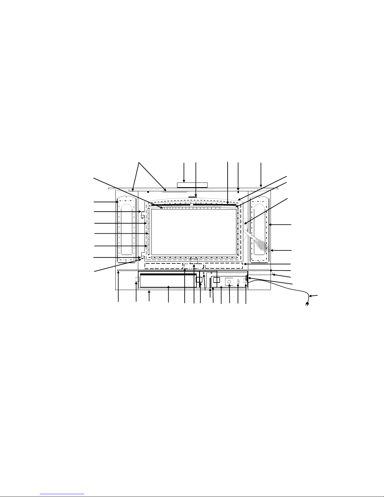
MODEL 94NC
WOOD STOVE
(1)
(22)
(42)
(20)
(33)
(18)
(14)
(40)
(8)
1. Secondary air tubes
2. Blower control (rheostat)
3. Primary air control
4. Warm air outlets
5. Baffles (interior of stove)
6. Air inlet
7. Cast Door
8. Hearth extension
9. Power cord
10. Disc thermostat
11. Motor guard screen
12. Automatic/off/man. switch
13.
Bottom secondary air channel
14. Hinge Block
(4)
(41)
(26)
(36)
(29)
(13)
15. Pipe stop
16. Outer top
17. Door glass
18. Glass clips
19. Hearth
20. Door gasket
21. Side glass
22. Side glass gasket
23. Firebrick
24. Motor
25. Motor mount bracket
26. Cover Door
27. Cover door screws
28. Shot gun air box
(15)
(17)
(28)
(27)
(34)
(25)
(24)
(39)
(11)
(2)
(5)
(12)
(16)
(21)
(35)
29. Ash pan
30. Bay side overlay
31. Door handle & spring handle
32. Top air wash
33. Cast door glass gasket
34. Cover door hinge
35. Magnet holder
36. Cover door Magnet
37. Door latch
38. Door latch screw
39. Top baffle board
40. Hinge pins
41. 8" Flue exit
42. Hinge cap
(7)
(32)
(37) & (38)
(30)
(31)
(23)
(19)
(3)
(10)
(9)
Page 4
F
B
A
E
C
D
F
B
E
D
SECTION II
MASONRY INSERT INSTALLATION
The Model 94NC may be installed using an all masonry fireplace built in accordance with
Uniform Building Code and National Fire Protection Association (NFPA). The first step in
this type of installation is to determine acceptability of the fireplace and chimney for use with a
woodstove, both construction and condition of fireplace are important considerations when installing a woodstove. The chimney should extend at least 3' above roof and
at least 2' above any point of roof within 10'.
CAUTION
REMEMBER TO HAVE YOUR CHIMNEY INSPECTED FOR LEAKS AND BLOCKAGE
BEFORE YOU INSTALL YOUR STOVE. DO NOT CONNECT THIS UNIT TO A
CHIMNEY FLUE SERVING ANOTHER APPLIANCE.
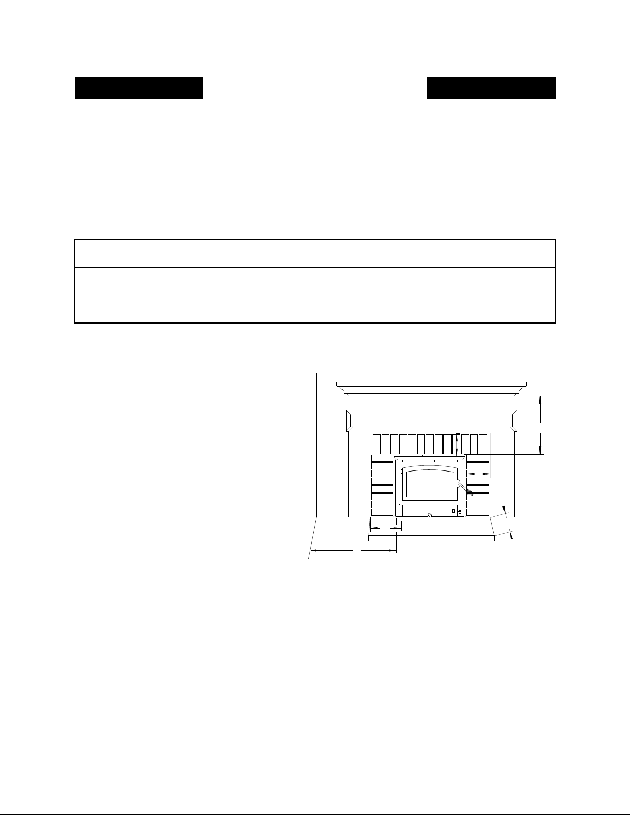
MINIMUM CLEARANCE MASONRY INSERT
MODEL 94NC
A. Side Wall Combustible
B. Front Floor Protector
C. Side Floor Protector
D. Side Wood Trim
E. Top Wood Trim
F. Mantel or Brackets
12"
16"
8"
10"
18"
24"
1. The hearth must be of masonry construction and must extend a minimum of 16" in front of
the firebox opening and a minimum of 8" to either side of the firebox opening.
Minimum floor protection under unit must have an R-value of 0.30.
2. If there is no minimum hearth protection from front of firebox opening and front of
masonry hearth, a floor protector must be used in front of hearth to protect combustible
materials. The floor protector must be 3/8" minimum thickness non-combustible material or
equivalent.(See Page 12,13).
Page 5

POSSIBLE TOOLS NEEDED FOR INSTALLATION
If you decide to install your own stove, there are several hand tools you may need to do the job.
If you do not already have them they are readily available at most hardware stores.
Caulking gun
Large adjustable wrench (may not be needed)
Drop cloths or newspapers
Vacuum cleaner or whisk broom
Flashlight
1 tube of RTV silicone, Code 103 or 106, or high temperature rubber cement rated between
450o F- 600o F
7/32" drill bit and drill
Socket/Ratchet Set
INSTALLATION PREPARATION
Fireplace:
1. Relocate furniture and other materials away from front of fireplace to allow free access to
fireplace.
2. Cover hearth and adjacent floor areas with drop cloths to protect from soiling or marring
surface.
3. Remove existing fireplace damper plate.
4. Thoroughly clean fireplace of ashes and soot.
5. Check chimney and smoke chamber for excessive buildup of creosote or soot. Also, check
for obstructions, such as bird’s nests. If chimney is excessively dirty, clean it or have
someone clean it professionally BEFORE installing or using room heater.
6. If fireplace has an ash dump or outside air provision, these must be sealed off with metal or
tightly packed non-combustible insulation to prevent cold air from entering fireplace
chamber.
MASONRY INSERT INSTALLATION
INSTALLATION OPTIONS
This unit (appliance) may be installed into an all masonry fireplaces, built in accordance with
Uniform Building Code and National Fire Protection Association (NFPA 211).
NOTE: Check with local building officials for any permits required for installation of this unit
and notify your insurance company before proceeding with installation
It is imperative that your fireplace and oversize flue liner meets applicable codes. It is recommended that one of the flowing procedures be followed.
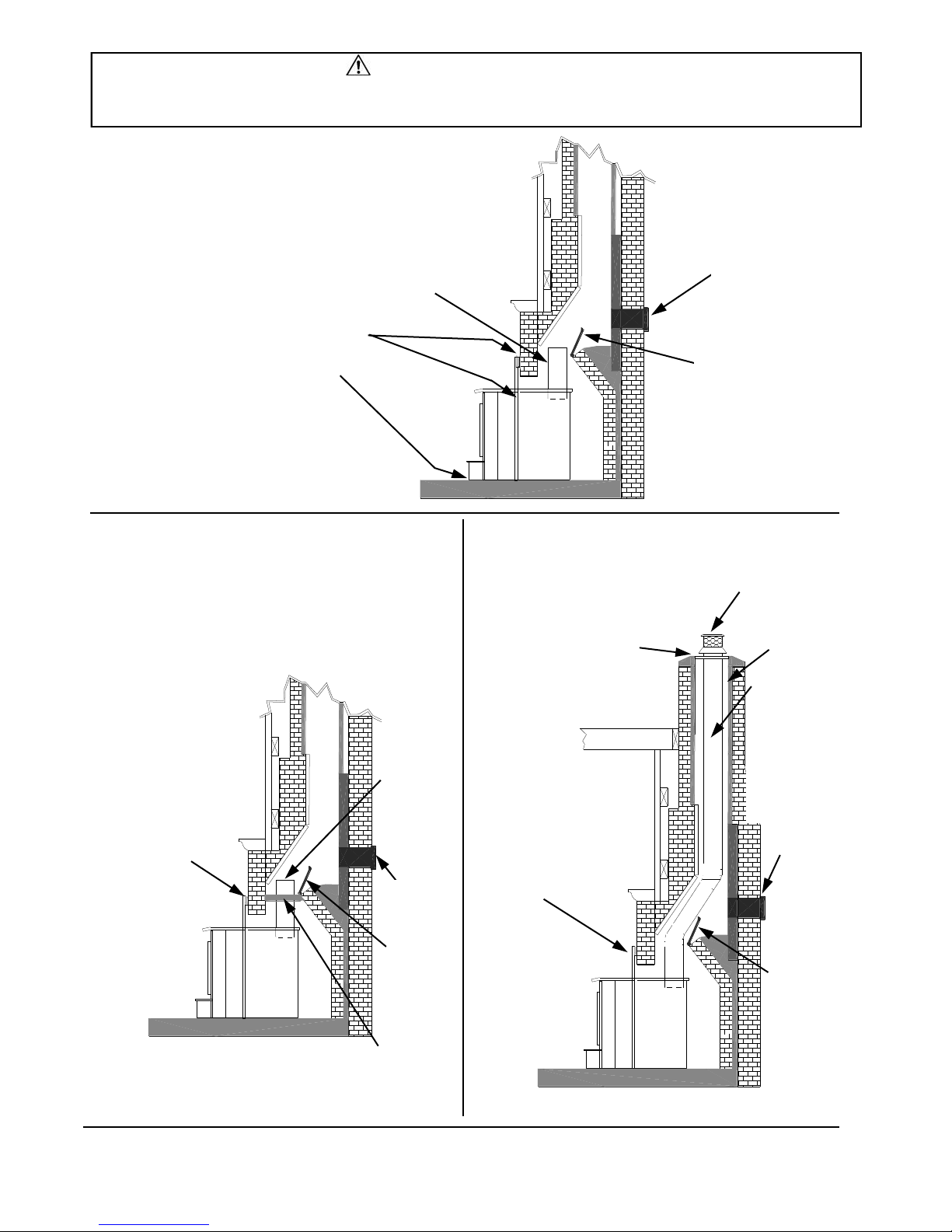
A. A Chimney Connector can be installed from appliance flue exit through damper with
an air-tight face seal. See option (A) Figure 2, page 7.
B. A listed Direct Connect can be installed from appliance flue exit through damper into
first section of flue liner with an air-tight seal. See option (B) Figure 3, page 7.
C. A Positive Connect can be installed from appliance flue exit continuing up through en-
tire chimney and exiting at top of the chimney. See option (C) Figure 4, page 7.
Page 6
SAFETY NOTICE
If this appliance is not properly installed, a house fire may result. For your safety, follow the installation directions.
Contact local building or fire officials about restrictions and installation inspection requirements in your area.
OPTION (A) Figure 2,
AIRTIGHT INSU-
STARTER PIPE
SEAL TRIM PANELS AND UNDER
FRONT OF STOVE UNIT WITH
INSULATION OR HIGH
TEMPERATURE CAULK
NOTE: New Buck Corporation grants no warranty, implied or stated, for the installation or
maintenance of your appliance, and assumes no
responsibility of any consequential damage(s).
LATED CLEANOUT
REMOVE
DAMPER
OR WIRE
IT OPEN
OPTION (B) Figure 3,
NOTE: Follow installation instruction
with Direct Connection Kit.
(Kit sold separately)
SEAL TRIM PANELS
WITH INSULATION
OR HIGH
TEMPERATURE
CAULK
STAINLESS
STEEL
CHIMNEY
CONNECTOR MUST
EXTEND 1’
PAST THE
BLOCK-OFF
PLATE OR
TO THE
FLUE LINER
AIRTIGHT
INSULATED
CLEAN-OUT
REMOVE
DAMPER
OR WIRE IT
OPEN
OPTION (C) Figure 4,
NOTE: Follow installation
instruction with Positive
Connection Kit.
(Kit sold separately)
INSTALL A NON-COMBUSTIBLE
COVER PLATE TO PREVENT
WATER FROM ENTERING THE
CHIMNEY
TRIM PANELS
CAP(PREVENTS
WATER FROM
ENTERING)
FLUE
LINER
THE LINER MUST
BE STAINLESS
STEEL CONNECTOR OR FLEXIBLE
VENT. FOLLOW
THE LINER MANU-
FACTURER’S IN-
STRUCTIONS FOR
INSTALLATION
AND SUPPORT.
AIRTIGHT
INSULATED
CLEAN-OUT
REMOVE
DAMPER
OR WIRE
IT OPEN
BLOCK-OFF PLATE
OR DAMPER
ADAPTER
Page 7
INSTALLATION PROCEDURE
(Use a chimney connector or a Listed Direct or Positive Connect) (See Page 6).
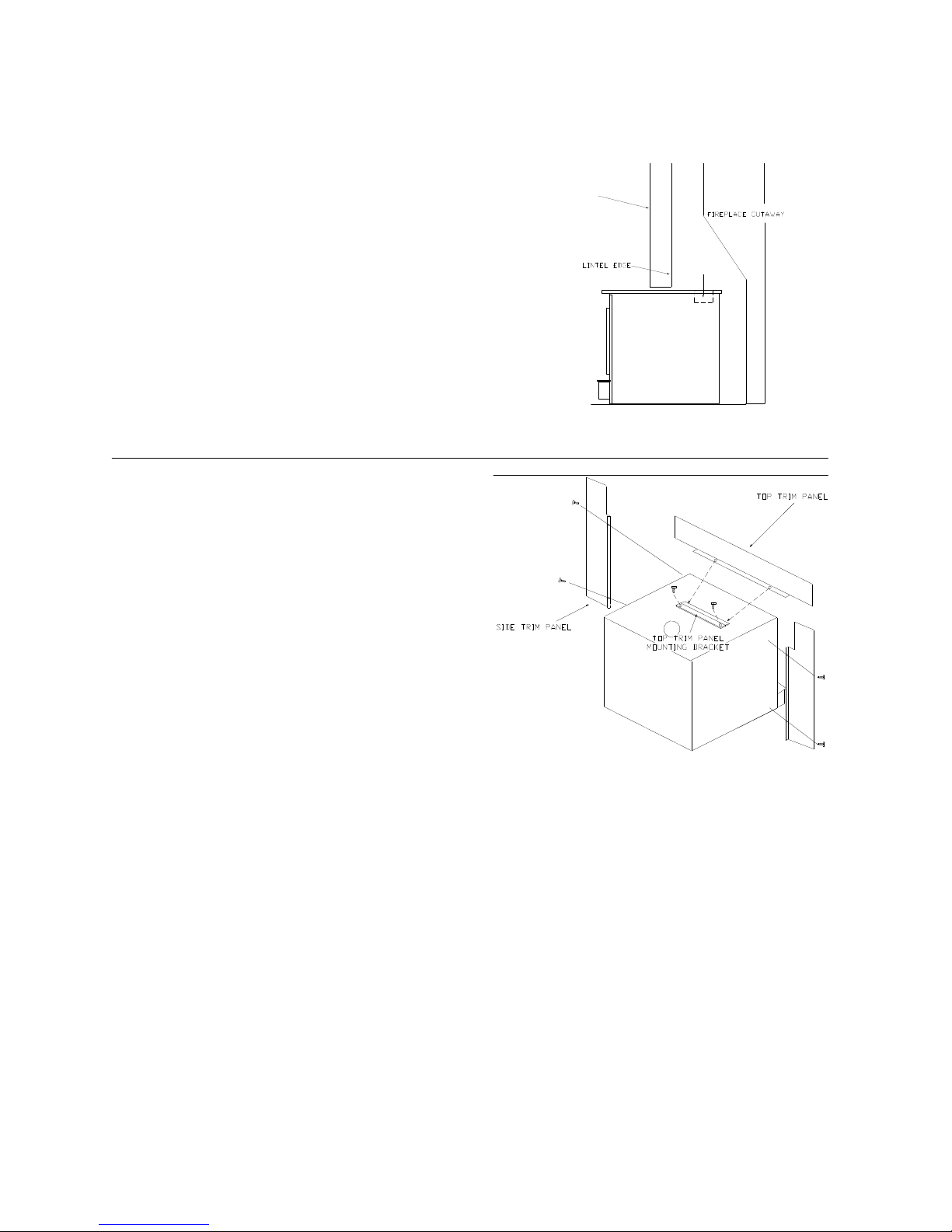
POSITIONING HEATER
FRONT OF FIREPLACE
When positioning heater, the following conditions
MUST be met. (See Figure 5).
1. The front of flue opening must be positioned
FLUE OPENING
BEHIND rear edge of the lintel to ensure proper
draft. (See Figure 5).
2. Center heater in fireplace opening.
FIGURE 5 POSITIONING
MOUNTING TRIM PANELS
NOTE: Mount top trim panel so that it sits in front of
top of side trim panels.
After unit is positioned, mark mounting position of trim
panels as follows:
1. Place side trim panels flat against face of fireplace.
Mark down front edge of trim panel with a pencil to
make a vertical reference line. (See Figure 6).
2. Set top (long) trim panel in place on top of unit.
The panel should be flat against the outside face
of fireplace, and standing vertically. Mark along
lower edge of trim panel with a pencil to make a
reference line for mounting.
3. Slide unit out of fireplace far enough to work
behind trim panel reference lines.
4. Mount side trim panels. (See Figure 6).
a. Position trim panel on reference line.
b. Drill mounting holes in center of trim panel mounting brackets to allow for adjustment in and out if neces-
sary.
c. Mount trim panel using self-tapping screws provided.
5. Place top panel back on reference mark. Take the top trim panel mounting bracket, position bracket so it overlaps rear lip of top trim panel. Drill mounting holes in top of stove using holes in bracket as guide. Tighten
down screws.
6. Now, follow installation procedures listed. Install heater and connect kit in fireplace. If not using one of
installation methods shown on (Page 7), then continue.
7. Slide unit back into fireplace. Check to be sure that trim panels are properly positioned so they lie flat against
front of fireplace. If one or more of panels is out of position, slide unit out and reset by loosening the
mounting screws and repositioning in the slot. Reinstall top trim panel by sliding rear lip of top trim panel
underneath front lip of mounting bracket.
FIGURE 6 MOUNTING TRIM PANELS
Page 8
 Loading...