

Page 1
MODEL 80
CATALYTIC WOOD STOVE
Buck Stove
FIREPLACE INSERT & FREESTANDING
FEATURES
PREPARATIONS INSTALLATION
OPERATION MAINTENANCE SAFETY
SAFETY NOTICE
IF THIS HEATER IS NOT PROPERLY INSTALLED, A HOUSE FIRE MAY RESULT.
FOR YOUR SAFETY, FOLLOW THE INSTALLATION INSTRUCTIONS.
CONTACT THE AUTHORITY HAVE JURISDICTION ( SUCH AS MUNICIPAL
BUILDING DEPARTMENT, FIRE DEPARTMENT, FIRE PREVENTION BUREAU,
etc.) CONSULT BEFORE INSTALLATION TO DETERMINE THE NEED TO
OBTAIN A PERMIT. KEEP THESE INSTRUCTIONS FOR FUTURE USE.
TESTED AND LISTED BY: ITS/WARNOCK HERSEY, MIDDLETON, WI
“MEETS PHASE II EPA STANDARDS”
MANUFACTURED BY NEW BUCK CORPORATION
200 ETHAN ALLEN DRIVE
PO BOX 69
SPRUCE PINE, N.C. 28777
www.buckstove.com
Revised January 2013
Page 2

Page 3

TABLE OF CONTENTS
SECTION I
Room Heater Features ..............................................................................................................3
Important Statements............................................................................................................5-6
SECTION II
Masonry Insert Installation................................................................................................. 7-11
SECTION III
Residential Freestanding Heater Installation................................................................... 12-18
SECTION IV
Wood Heater Safety................................................................................................................19
SECTION V
Operation ..........................................................................................................................20-21
SECTION VI
Preventive Maintenance/Parts Replacement ....................................................................22-23
SECTION VII
Troubleshooting................................................................................................................ 24-25
WARRANTY ..................................................................................................................26-27
Page 1
Page 4

Page 2
Page 5

SECTION I
The New Buck Corporation room heater Model 80 is one of the safest and most efficient heating systems
available when installed and operated as specified in these instructions and as stipulated on the operation and
installation labels affixed to the unit. The unit is designed to burn wood fuel only.
Please read this entire manual before you install and use your new room heater. Failure to follow instructions
may result in property damage, bodily injury or even death.
Throughout the manual, you will see this symbol. This indicates areas of importance regarding safety.
Please make a special note of these areas.
Install and use only in accordance with the manufacturer’s installation and operating instructions. Do not
connect this unit to a chimney flue serving another appliance. This unit is not designed for installation into a
Mobile Home.
ROOM HEATER FEATURES
Before attempting to install or operate your heater, it is a good idea to familiarize yourself with the features and
operating controls of the unit.
WARNING: Model 80 heater was not designed for fire grates.
NOTE: “Do not use grate or elevate fire. Build wood fire directly on inner bottom of fire box.”
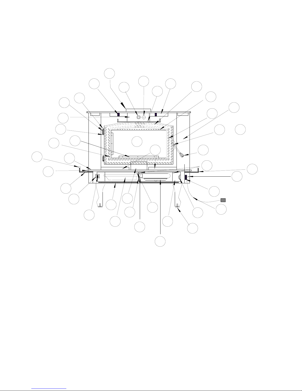
1. Bypass Damper: The bypass damper control is located in top center of heater front just under top. It is
operated by pushing or pulling the rod. The damper is fully open when the handle is pulled out and fully
closed when it is pushed in. The damper must be open before the door is opened.
2. Blower Control: The blower control (Rheostat) is located at bottom under hearth. This switch controls
the variable speed blower. For blower to operate turn switch from “OFF” position to either “LOW”,
“MEDIUM” or “HIGH”. When stove temperature reaches 110oblower will automatically come on.
3. Primary Air Controls: The primary air intake draft controls are located at the left and right side of the
hearth. They are operated by moving in and out to control the amount of primary air entering the firebox.
4. Warm Air Outlets: Provides heat extraction from the top of the firebox.
5. Baffles: Directs air flow around the unit for maximum heat transfer.
6. Air Inlet: Allows cool air near floor to be circulated through blower and back into warm air chamber of
heater.
7. Stand: Elevates heater above the floor for safety and a neat appearance.
8. Door: Provides an “airtight” feature. The door allows a much higher burning efficiency than can be
obtained with an open firebox.
9. Hearth Extension: Offers protection from spilled ashes and cinders.
10. Power Cord: Provides electrical power to operate the blower.
11. Chimney Connector: Used to connect unit to chimney or direct connect kit.
12. Catalysts: Enables the unit to burn cleanly and efficiently.
13. Catalyst Monitor: Hole is located to the right of the damper rod on the front. Remove plug and insert
probe provided by manufacturer.
14. Cover Door: Conceals blower, blower controls and ash pan.
15. Airway: Primary air is directed in such a way as to provide a “sweeping” air wash over the glass to assist
in keeping it clean.
16. Ash Pan: Provides for easy ash removal.
Page 3
Page 6
Model 80
14
10
13
Wood Stove
40
5
1
11
21
4
20
32
15
7
39
33
15
18
8
19
3A
35
6
36
29
1. By Pass Damper & Brass Spring Handle
2. BlowerControl (Rheostat)
3. Primary Air Control (Right Side)
3a. PrimaryAir Control (Left Side)
4. Warm Air Outlets
5. Baffles (Interior of Stove)
6. Air Inlet
7. Door
8. Hearth Extension
9. Power Cord
10. Catalyst (interior firebox)
11. Catalyst Probe
12. Automatic / Off / Man. Switch
13. Brass Cap
14. Hinge Block
15. Air ControlBrass Knobs
16. Shot Gun Air Control
17. Door Glass
18. Glass Clips
19. Hearth Brass
20. Door Gasket
Buck
Stove
28
34
17
25
16
23
37
&
31
27
2
30
9
26
22
24
21. Lower Heat Shield
22. Leveling Screws
23. Bottom Firebrick
24. Motor
25. MotorMount Bracket
26. Cover Door
27. Cover Door Screws
28. Shot Gun Air Box
29. Ash Pan
30. Disc Thermostat
31. Door Handle & Brass Spring Handle
32. Air Wash Screen
33. Glass Gasket
34. Cover Door Hinge
35. Magnet Holder
36. Cover Door Magnet
37. Door Latch
38. Door LatchScrew
39. Hinge Pins
40. 8" Flue Exit
12
8
3
3
Page 4
Page 7

EPACOMPLIANCE STATUS
This manual describes the installation and operation of the New Buck Corporation, Model 80 wood heater. This
heater meet the U.S. Environmental Protection Agency’s Emission limits for wood heaters sold after July 1, 1992.
Under specific test conditions this heater has been shown to deliver heat at rates ranging from approximately 9,000
to 40,300 BTU/hr for the Model 80.
The Model 80 catalytic solid fuel (wood) burning combination room heater/fireplace stove manufactured by New
Buck Corporation complies with :UL 1482 (1996), :UL 1482 (2010) for residential freestanding and masonry
fireplace insert installations when constructed and installed in accordance with ITS approved documentation.
CATALYST EQUIPPED
This wood heater contains a catalytic combustor, which needs periodic inspection and replacement for proper
operation. It is against the law to operate this wood heater in a manner inconsistent with operating instructions in
this manual or if the catalytic element is deactivated or removed.
CATALYSTWARRANTY
The combustor supplied with this heater is a 3 cell catalyst with an overall dimension of 2" x 6" x 7". Consult the
catalytic combustor warranty also supplied with this heater. All warranty claims should be addressed to:
Applied Ceramics
Customer Service Department
P.O. Box 29664
Atlanta, GA 30359
770-448-6888
See enclosed catalyst warranty for instructions. New Buck Corporation does not handle catalyst replacements.
Customer can order direct form Applied Ceramics.
PROPER FUEL SELECTION
This heater is designed to burn natural wood only. Higher efficiencies and lower emissions generally result when
burning air dried natural seasoned hardwoods, as compared to softwoods or to green or freshly cut hardwoods.
DO NOT BURN:
Treated Wood Garbage Solvents Trash
Coal Cardboard Colored Paper
Burning treated wood, garbage, solvents, colored paper or trash may result in release of toxic fumes and may
poison or render the catalytic combustor ineffective.
Burning coal, cardboard or loose paper can produce soot or large flakes of char or fly ash that can coat the
combustor, causing smoke spillage into room and rendering the combustor ineffective.
ACHIEVING CATALYTIC LIGHT-OFF
The temperature in the stove and the gases entering the combustor must be raised to between 500oF to 700oF for
catalytic activity to be initiated. This can be determined with the use of a catalyst monitor (TM-20). During the
start up of a cold stove a medium to high firing rate must be maintained for about 20 minutes. This ensures that the
stove, catalyst, and fuel are all stabilized at proper operating temperatures. Even though it is possible to have gas
temperatures reach 600oF within two to three minutes after a fire is started, if the fire is allowed to die down
immediately it may go out or the combustor may stop working. If this happens open the damper to raise the
temperature to activate the catalyst. Once the combustor starts working, heat generated in it by burning the smoke
will keep it working.
Page 5
Page 8

ACHIEVING CATALYTIC LIGHT-OFF WHEN REFUELING
During the refueling and rekindling of a cool fire or a fire that has burned down to the charcoal phase, operate the
stove at a medium to high firing rate for about 15 minutes to ensure that the catalyst reaches approximately 600oF.
CATALYST MONITORING
It is important to periodically monitor the operation of the catalytic combustor to ensure that it is functioning
properly and to determine when it needs to be replaced. A non-functioning combustor will result in a loss of
heating efficiency and an increase in creosote and emissions.
This catalytic heater is equipped with the means to install a temperature probe to monitor catalyst operation.
Properly functioning combustors typically maintain temperatures in excess of 1000oF. If catalyst temperatures are
not in excess of 500oF refer to Catalyst Troubleshooting Section of this owner’s manual.
CAUTIONAGAINST OVER-FIRING
Do not over-fire this heater.
Attempts to achieve heat output rates that exceed heater design specifications can result in permanent damage to the
heater and to the catalytic combustor.
ASH REMOVAL
Whenever ashes build up in the firebox and when fire has burned down and cooled, remove excess ashes. Leave an
ash bed approximately 1 inch deep on firebox bottom to help maintain a hot charcoal bed. To remove ashes,ash
dump is located at the left inner bottom. By lifting the dump door, place ashes through dump opening. The ashes
fall directly into ash pan. The ash pan is located at the left side under the hearth behind cover door.
NOTE: Be sure to turn the room air blower off before removing ashes. Open cover door and slide ash pan out.
NOTE: Fueling and ash removal door (s) must remain closed when in operation.
Ashes should be placed in a metal container with a tight fitting lid. The closed container of ashes should be placed
on a non-combustible floor or on the ground, away from all combustible materials, pending final disposal. The
ashes should be retained in the closed container until all cinders have thoroughly cooled.
NOTE: Be sure to turn room air blower back on when job is completed.
NOTE: The room heater is not to be connected to any air distribution duct.
CREOSOTE - FORMATIONAND NEED FOR REMOVAL
When wood is burned slowly, it produces tar and other organic vapor, which combined with expelled moisture
forms creosote. The creosote vapors condense in the relatively cool chimney flue of a slow-burning fire. As a
result, creosote residue accumulates on the flue lining. When ignited this creosote makes an extremely hot fire.
Page 6
Page 9
SECTION II
MASONRYINSERT INSTALLATION
INSTALLATION OPTIONS
This unit (appliance) may be installed into an all masonry fireplace, built in accordance with the Uniform Building Code
and the National Fire Protection Association (NFPA 211).
NOTE: Check with local building officials for any permits required for installation of this stove and notify your insurance
company before proceeding with installation.
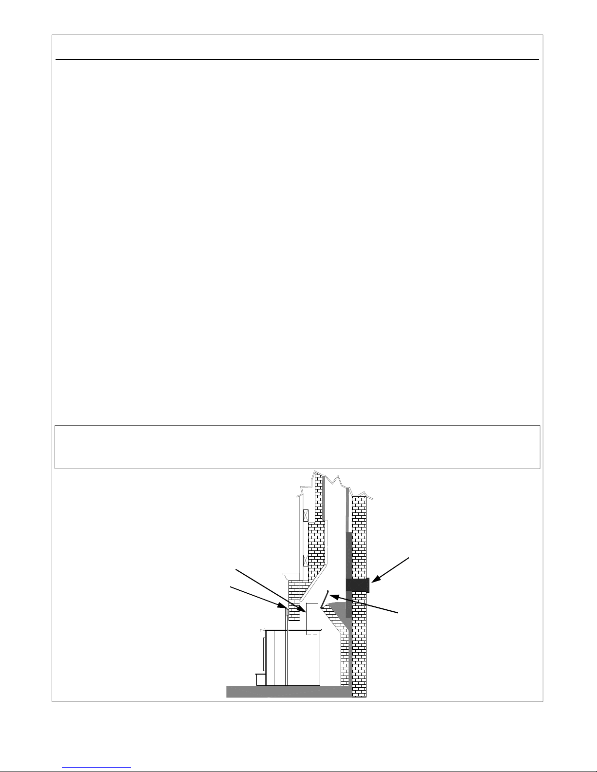
OPTION A. See Below
At a minimum, a starter pipe reaching from the stove flue exit to the base of the existing code approved
masonry chimney (flue-liner) and an airtight face seal.
OPTION B. See Page 8.
Direct connection: In accordance with NFPA-211-9-4.5, Connection to Masonry Fireplaces. A solid fuel-burning
appliance such as a stove or insert shall be permitted to use a masonry fireplace flue where the following conditions
are met:
Exception: Listed fireplace accessories shall be permitted to use a masonry fireplace flue.
1. There is a connector that extends from the appliance to the flue liner.
2. The cross-sectional area of the flue is no more than three times the cross-sectional area of the flue collar of the
appliance.
3. If the appliance vents directly through the chimney wall above the smoke chamber, there shall be a noncombustible
seal below the entry point of the connector.
4. The installation shall be such that the chimney system can be inspected and cleaned.
5. Means shall be provided to prevent dilution of combustible products in the chimney flue with air from the habitable
space.
OPTION C. See Page 8.
It may be necessary to positive connect this unit to enhance the performance, if any of the following conditions exists:
1. Poor Drawing Flue 3. Double Flues 5. Stone Front Fireplace/ or damaged flue liner
2. Oversized Flue (17” x 7) 4. Ash Dump 6. Chimney that does not exceed 12’
Check with your dealer if any of the above conditions exist, before installing your stove. Proper installation is critical to
the performance of the Model 80.
Use Fireplace Kit PAFP80 for installation. An optional oversized fireplace kit is available for larger fireplaces. Check
with dealer.
SAFETY NOTICE
If this appliance is not properly installed, a house fire may result. For your safety, follow the installation directions.
Contact local building or fire officials about restrictions and installation inspection requirements in your area.
OPTION (A)
AIRTIGHT INSU-
STARTER PIPE
SEAL TRIM PANELS WITH INSULATION / AND OR HIGH TEMPERATURE
CAULK
NOTE: New Buck Corporation grants no
warranty, implied or stated, for the installation
or maintenance of your appliance, and assumes
no responsibility of any consequential damage
LATED CLEANOUT
REMOVE
DAMPER
OR WIRE
IT OPEN
Page 7
Page 10
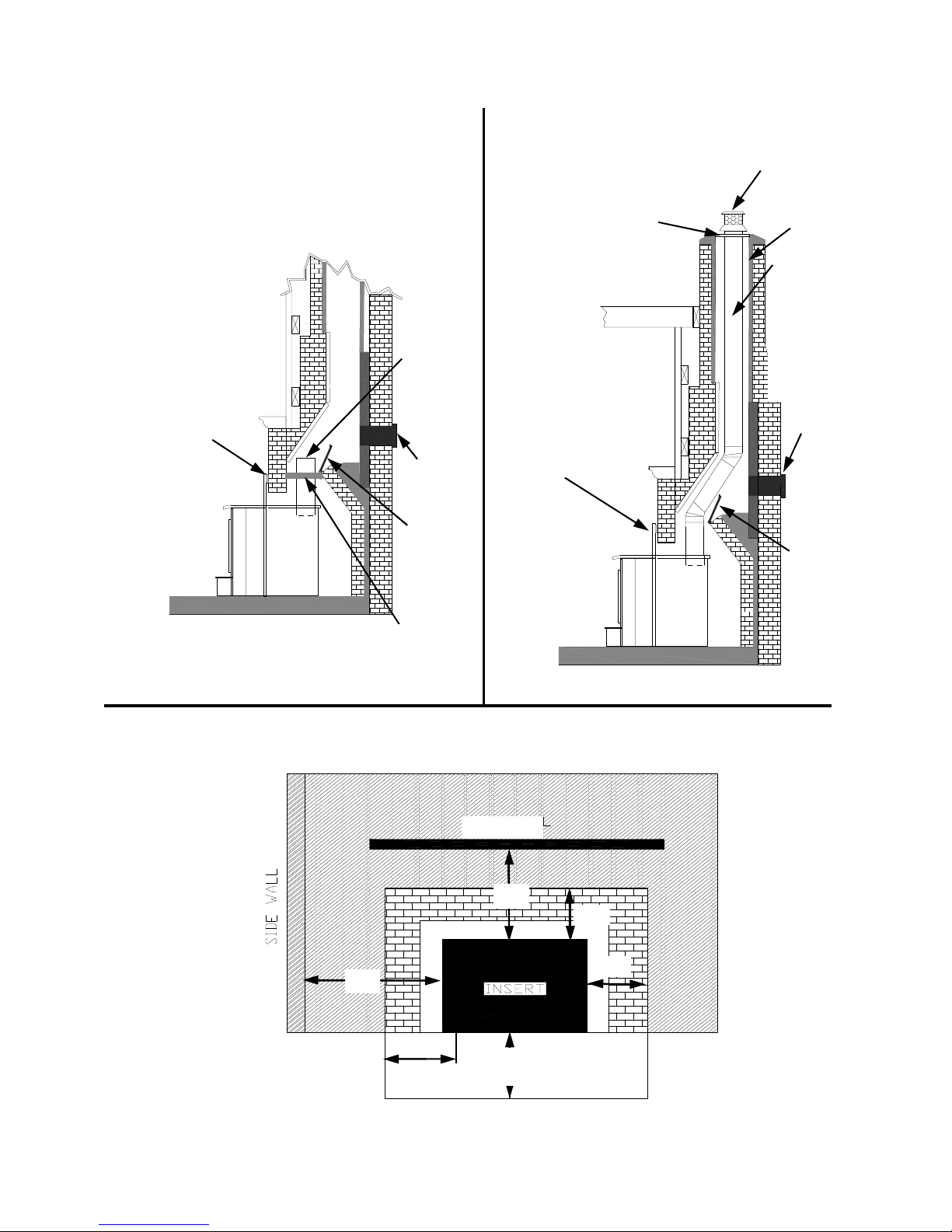
OPTION (B) OPTION (C)
NOTE: Follow installation
instruction with Positive
Connection Kit.
NOTE: Follow installation instruction
with Direct Connection Kit.
(Kit sold separately)
SEAL TRIM PANELS
WITH INSULATION /
AND OR HIGH TEMPERATURE CAULK
STAINLESS
STEEL
CHIMNEY
CONNECTOR MUST
EXTEND 1’
PAST THE
BLOCK-OFF
PLATE OR
TO THE
FLUE LINER
AIRTIGHT
INSULATED
CLEAN-OUT
REMOVE
DAMPER
OR WIRE IT
OPEN
(Kit sold separately)
INSTALL A NON-COMBUSTIBLE
COVER PLATE TO PREVENT
WATER FROM ENTERING THE
CHIMNEY
TRIM PANELS
CAP(PREVENTS
WATER FROM
ENTERING)
FLUE
LINER
THE LINER MUST
BE STAINLESS
STEEL CONNECTOR OR FLEXIBLE
VENT. FOLLOW
THE LINER MANUFACTURE’S INSTRUCTIONS FOR
INSTALLATION
AND SUPPORT.
AIRTIGHT
INSULATED
CLEAN-OUT
REMOVE
DAMPER
OR WIRE
IT OPEN
BLOCK-OFF PLATE
OR DAMPER
ADAPTER
INSTALLATION (Fireplace Insert)
Minimum Clearances to Combustible Materials (in inches)
MANTEL
24"
12"
16"
HEARTH EXTENSION
FIGURE 1
FIREPLACE INSERT
8"
9"
9"
Page 8
Page 11

MINIMUM CLEARANCES:
The Model 80 Bay Fireplace Insert is intended for installation in accordance with standard for chimneys, fireplaces, vents
and solid-fuel burning appliances. NFPA-211 Code: NOTE-This model is not intended for installation into Zero Clearance or pre-fabricated fireplace.
1. The hearth must be of masonry construction and must extend a minimum of 16" in front of the firebox opening and a
minimum of 8" to either side of firebox opening.
2. Floor protector must be 3/8" minimum thickness non-combustible material or equivalent.
3. If your fireplace has wood trim above it, the wood trim musts be at least 9" above top of the unit and may be a maximum of 1/2" thick.
4. If your fireplace has a wood mantel, mantel or mantel supports must be located at a height of 24" above top of stove.
REQUIRED FIREPLACE DIMENSIONS
Minimum fireplace dimensions:
Height Width Depth
Min. Max. Min. Max. Min.
Model 80 23 1/2" 32 1/2 29" 46” 15 1/2"
POSSIBLE TOOLS NEEDED FOR INSTALLATION
If you decide to install your own stove, there are several hand tools you may need to do the job. If you do not already have
them, they are readily available at most hardware stores.
Caulking gun
Large adjustable wrench (may not be needed)
Drop cloths or newspapers
Vacuum cleaner or whisk broom
Flashlight
1 tube of RTV silicone, Code 103 or 106, or high temperature rubber cement rated between 450oF- 600oF.
7/32" drill bit and drill
Socket/Rachet Set
Insulation (Provided in Trim Kit package)
INSTALLATION PREPARATION
Fireplace:
1. Locate furniture and other materials away from the front of fireplace to allow free access to fireplace.
2. Cover hearth and adjacent floor areas with drop cloths to protect from soiling or marring surface.
3. Remove existing fireplace damper plate.
4. Thoroughly clean fireplace of ashes and soot.
5. Have your existing chimney inspected before inserting this unit. Some chimneys must be relined or replaced before
they are safe to use.
6. Check chimney and smoke chamber for excessive buildups of creosote or soot. Also, check for obstructions, such as
bird’s nests. If chimney is excessively dirty, clean it or have someone clean it professionally BEFORE installing or
using the room heater.
7. If fireplace has an ash dump or outside air provision, these must be sealed off with metal or tightly packed noncombustible insulation to prevent cold air from entering fireplace chamber.
Heater:
1. Inspect unit for any obvious physical damage.
2. Check primary air draft controls to ensure that they slide freely.
3. Check operation of the damper control to ensure it will open and close properly.
4. Check Manual/Automatic Switch to ensure that motor is working. *Place switch in “MANUAL” position.
(Plug in stove.) You cannot check motor in the “AUTOMATIC” position, unless a heat gun is used to heat
internal thermostat.
Page 9
Page 12
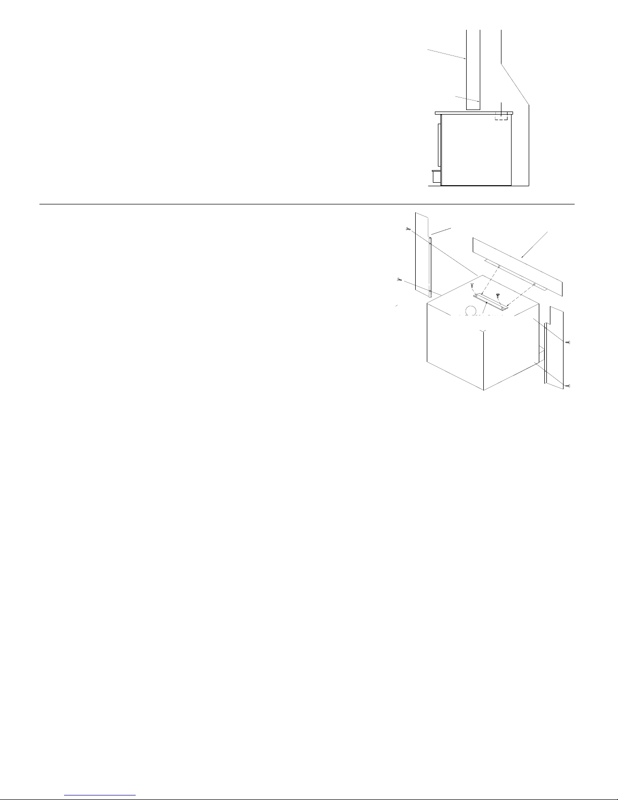
POSITIONING HEATER
When positioning the heater, the following conditions MUST be met! (See Figure
2).
1. The front of the damper opening must be positioned BEHIND the rear edge
of the lintel to ensure proper draft. (See Figure 2).
2. Center the heater in the fireplace opening.
VERTICAL PLANE
FIRE PLACE CUT AWAY
LINTEL EDGE
DAMPER
OPENING
FIGURE 2 POSITIONING
MOUNTING TRIM PANELS
After the unit is positioned, mark the mounting position of the trim panels as
SIDE TRIM PANEL
TOP TRIM PANEL
follows:
1. Place side trim panels flat against the face of the fireplace. Mark the front
edge of the trim panel with a pencil to make a vertical reference line. (See
Figure 3).
2. Place top (long) trim panel on top of the unit. The panel should be flat
against the outside face of the fireplace, and standing vertically. Mark along
the lower edge of the trim panel with a pencil to make a reference line for
TOP TRIM PANEL
MOUNTING BRACKET
mounting.
3. Slide the unit out of the fireplace far enough to work behind the trim panel
reference lines.
4. Mount the side trim panels. (See Figure 3).
a. Position the side trim panel on the reference line.
b. Drill mounting holes in center of side trim panel mounting brackets
to allow for adjustment in and out if necessary.
FIGURE 3 MOUNTING TRIM PANELS
c. Mount the trim panel using the self-tapping screws provided.
5. Place top trim panel on reference mark. Top trim panel mounting bracket (supplied) must overlap rear lip of top trim panel.
Drill mounting holes in top of stove using holes in bracket as guide. Tighten screws.
6. Follow installation procedures in the listed direct connect or positive connect kit you are using and install the heater and connect kit in the fireplace. If not using one of the installation methods shown on
Page 8, continue.
7. Slide the unit back into the fireplace. Check to be sure that the trim panels are properly positioned and lie flat against the front
of the fireplace. If one or more of the panels is out of position, slide the unit out and reset by
loosening the mounting screws and repositioning in the slot.
8. Reinstall the top trim panel by sliding the rear lip of the top trim panel underneath the front lip of the mount-
ing bracket already secured to top of unit.
NOTE: Mount the top trim panel so that it sits in front of the top of the side trim panels.
9. Obtain the brass trim kit provided with insert kit and slip over the top and sides of trim panels. Top ends of brass may need to be
trimmed to fit (See Figure 4).
10. Using insulation provided, peel and stick to back of panels overlapping fireplace dimensions by 1" on each
side and top. (See Figure 4A).
11. Next using high heat silicone or furnace cement run heavy bead of caulking around where panels meet the
stove. (See Figure 4A).
12. Slide the unit back into the fireplace. Check to be sure that the trim panels (and brass) are properly positioned
and lie flat against the front of the fireplace. If panels are out of position, slide the unit out and reset by loos
ening the mounting screws and repositioning in the slot. With bar lift stove up in front. Place insulation
across front and the surface of hearth or bottom of fireplace to make complete seal.
13. To check seal of panels, use candle flame and go around the entire area sealed by silicone and insulation. If flame leans toward
inside of fireplace, add additional insulation. This ensures an airtight seal.
Page 10
Page 13
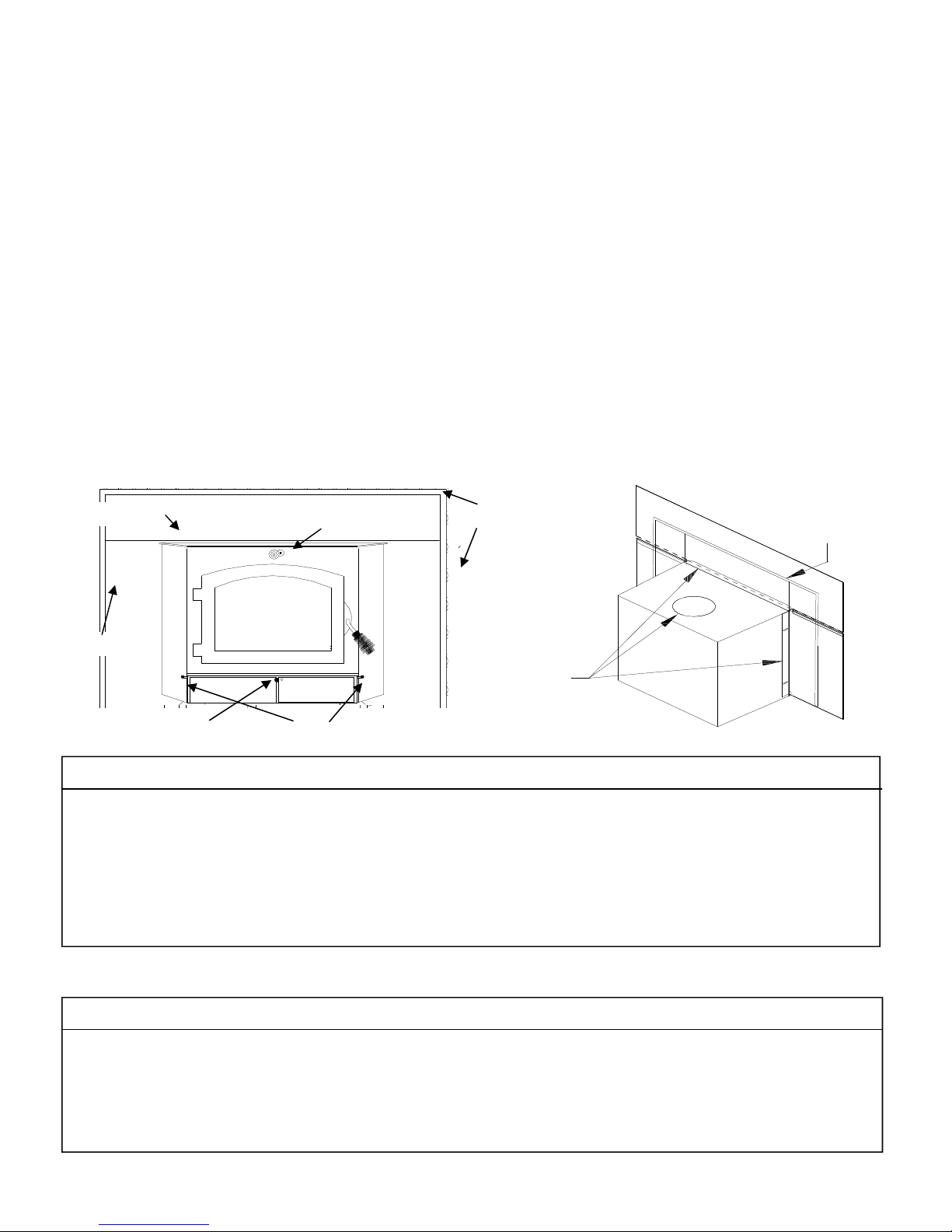
FINAL CHECK
1. Recheck specified clearances.
2. Remove all foreign material from firebox area.
3. Open air controls.
Primary Air Controls: The primary draft control is located at right and left side of hearth: to open push in, to close
pull out.
Secondary Air Control: The secondary draft control is located at the center bottom of hearth: to open pull out, to close
push in.
Damper Bypass Control: The damper bypass control is located at the center top of stove. To close push in, to open pull out.
(See Figure 4).
4. Plug power cord into a 115V AC outlet if optional motor is being used. “Do not run cord under unit or in high traffic areas.
5. Place rumpled pieces of newspaper in stove. Light it and close door. Ensure that stove draws properly through the primary
draft.
NOTE: “Do not use grate or elevate fire. Build wood fire directly on inner bottom of fire box.”
6. Check for smoke leaks around door.
7. Open door and check for smoke escaping from front of stove. Smoking usually indicates a defective or poorly positioned
chimney. Some chimneys with a marginal draft can be pre-heated by lighting newspaper and holding it near open damper
with a poker or fire tong. Once chimney heats up, a proper draft can usually be obtained.
If a thorough review of Troubleshooting Guide in the rear of manual does not reveal problem, contact your dealer for assistance.
Top Trim Panel
Side Trim Panel
Secondary Air control
Bypass Air Control
Primary Air Controls
FIGURE 4
Outer Trim
HIGH TEMP
SILICONE
FIGURE 5
INSULATION
CAUTION
THE UNIT IS PAINTED WITH A SPECIALLY FORMULATED HIGH TEMPERATURE PAINT
THAT CURES DURING THE FIRST TWO OR THREE FIRINGS. YOU MAY NOTICE A
SLIGHT SMOKING EFFECT AND AN ODOR OF BURNING PAINT WHEN YOU BUILD THE
FIRST FIRES. THIS IS NORMAL AND IS NOT A CAUSE FOR ALARM. IN SOME CASES,
THESE FUMES WILL ACTIVATE A SMOKE ALARM. OPENING A WINDOW NEAR UNIT
WILL ALLOW THESE FUMES TO ESCAPE. DO NOT BUILD A LARGE, ROARING FIRE
UNTIL THIS CURING IS COMPLETE OR HEATER FINISH MAY BE DAMAGED.
The connector and/or chimney should be inspected at least once a month during heating season to
determine if a creosote buildup has occurred.
NEVER USE GASOLINE, GASOLINE-TYPE LANTERN FUEL, KEROSENE,
CHARCOAL LIGHTER FLUID OR SIMILAR LIQUIDS TO START OR "FRESHEN UP" A
FIRE IN HEATER. KEEP ALL SUCH LIQUIDS WELL AWAY FROM STOVE WHEN IT IS IN
USE. ALL FLUIDS OF THIS TYPE GIVE OFF VOLATILE FUMES AND CAN AND WILL
EXPLODE!! DON'T TAKE A CHANCE WITH THE SAFETY OF YOUR HOME AND FAMILY.
CAUTION
Page 11
Page 14
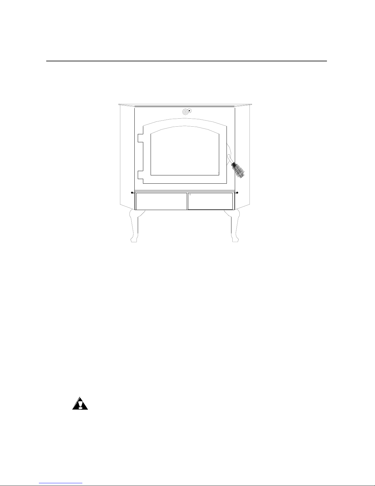
SECTION III
RESIDENTIAL FREESTANDING ROOM HEATER
INSTALLATION
INSTALLATION PRECAUTION
Extensive field and laboratory testing has shown that catalytic stoves perform best as freestanding stoves when
vented into a masonry chimney that include the following:
1. A rain cap is installed on chimney.
2. Height of chimney is at least 15 feet high.
3. Location of chimney is interior (not on an outside wall).
Satisfactory results have been reported with installations other than listed above. However, draft problems are
possible if a hot chimney is not maintained.
Use pedestal kit as follows:
Model 80 #4171B
CAUTION: Do not connect this unit to a chimney flue serving another appliance.
Page 12
Page 15
MODEL 80
BACK WALL
Minimum Clearances
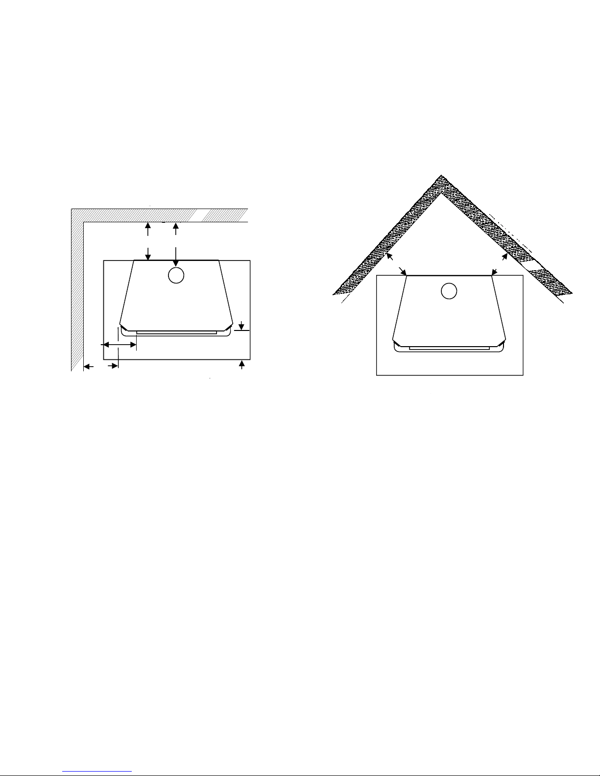
The New Buck Corporation Model 80 must be installed in compliance with instructions contained in this manual.
Clearance from combustible walls and ceilings. (Using single wall chimney connector)
The minimum lateral distance between any part of room heater and combustible wall is shown in Figures 6 and 7.
BACK WALL
F
A
D
B
G
SIDE WALL
E
I
A
C
FIGURE 6
A B C D E I J
MODEL 80 29” *18” 25” 26” 20” 8” 16”
*Chimney connector to ceiling (see page 14).
D
J
MINIMUM CLEARANCES
E
FIGURE 7
E
FLOOR PROTECTION
If a freestanding model is to be installed on a combustible floor, a non-combustible pad must be placed below it to
protect floor from burning material from stove. Floor protector must be 3/8" in minimum thickness, noncombustible material or equivalent.
The unit must be positioned on the pad so that there is a minimum of 16" from front of door opening to front of pad,
and a minimum of 8" measured horizontally from sides of fuel loading and ash removal openings to sides of pad.
NOTE: For clearance reductions using wall protectors, refer to the NFPA-211 Code.
TOOLS FOR INSTALLATION
Drop Cloth
Electric Drill with 7/32" drill bit
1/2" - 9/16" combination wrench
3/8" magnetic socket chuck adapter, 3/8" wrench (box or socket) or adjustable wrench
Socket Set
Tape Measure
Pencil
Level
Screw Driver
Page 13
Page 16
Preparing Stove for Installation
1. Inspect unit for any obvious physical damage.
2. Check primary air draft controls to ensure that they slide freely.
3. Check the operation of bypass damper control to ensure that it will open and close properly.
4. Remove any items from within firebox. Spread a drop cloth on floor behind heater. Next, tilt heater so that
back is on drop cloth.
5. Using a tape measure, make a line down 3" from front of heater.
6. Open corresponding box and obtain pedestal. Place pedestal against bottom of heater (angle side to heater) at
marked line. Center pedestal left and right and mark screw locations on bottom through outer holes of pedestal
mounting angles. Set pedestal aside and drill four 7/32" holes in heater bottom.
7. Obtain four 1/4" self tapping screws and secure pedestal to heater.
8. If you chose legs rather than a pedestal, open box, attach legs to pre-drilled holes in bottom of heater.
9. Reposition heater to upright position.
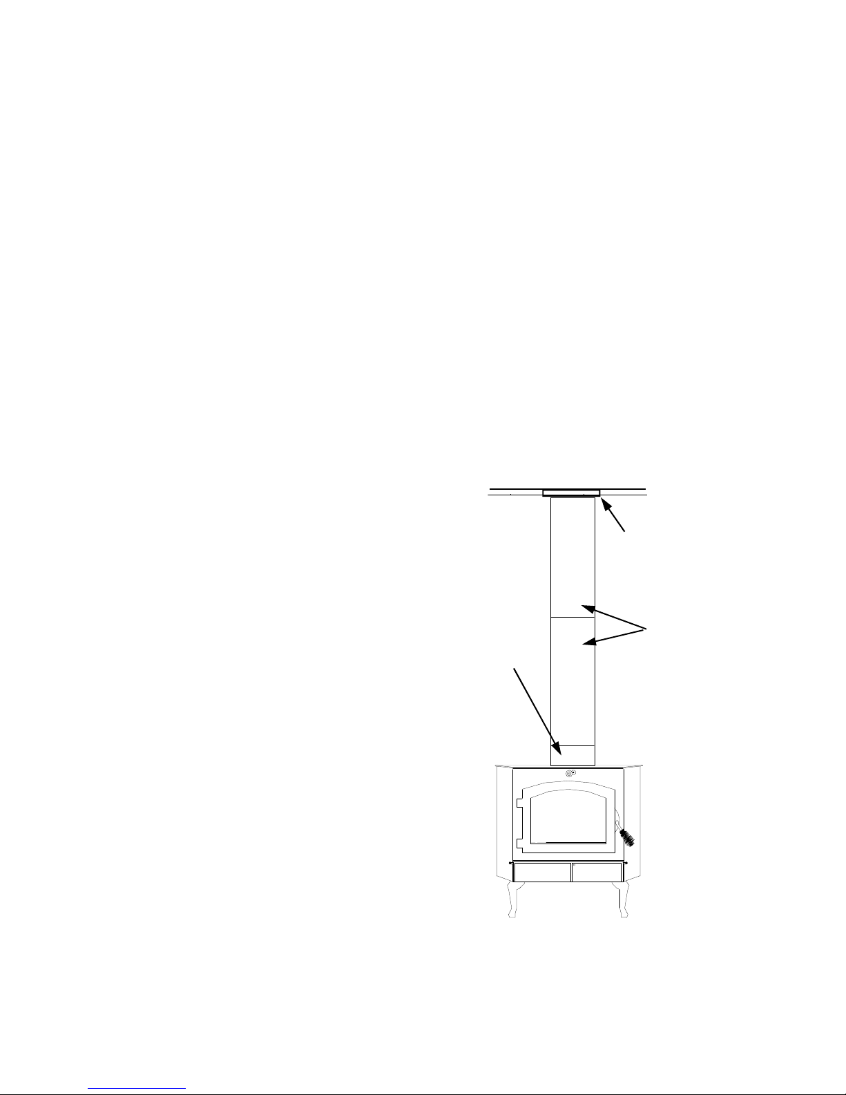
10. Obtain chimney connector from your dealer. Position on top of stove at flue exit. Position the two “J” bolts in
connector using lock washer and nuts provided. Lock in place.
CHIMNEY
Ceiling Exits (using Single Wall Pipe and UL 103
HT type chimney system listed with manufacturer
in this section of manual)
The Model 80 is designed for connection to:
(1) Simpson Duravent (2) Security (3) Selkirk
Metalbestos (4) Metal Fab (5) Air Jet, listed as
2100 degree pipe and parts.
Follow the chimney and chimney connector manufracture's instructions and local building codes for
installation through combustible walls or ceilings.
This room heater must be converted to (1) a chimney complying with the requirements for Type HT
chimneys in the Standard for Chimneys, FactoryBuilt, Residential, Type and Building Heating Appliance, UL 103, or (2) a code approved masonry
chimney with a flue liner.
Caution: Certain installation types require use of
certain chimney types. Please follow these
instructions exactly.
BUCK STOVE
CHIMNEY
CONNECTOR
CEILING
SUPPORT BOX
SINGLE WALL
PIPE
DETERMINING CHIMNEY
LOCATION
1. Suspend a plumb bob from ceiling above unit so
that weight is hanging in the center of flue exit.
(A small weight on a string will serve as a
plumb bob.) Mark ceiling where string is
suspended to locate center of chimney.
2. After locating center of hole, install ceiling
support box, chimney or chimney connector,
flashing and rain cap per chimney
manufacturer’s instructions and local building
codes for installation through combustible walls
or ceilings.
FIGURE 8
Page 14
Page 17
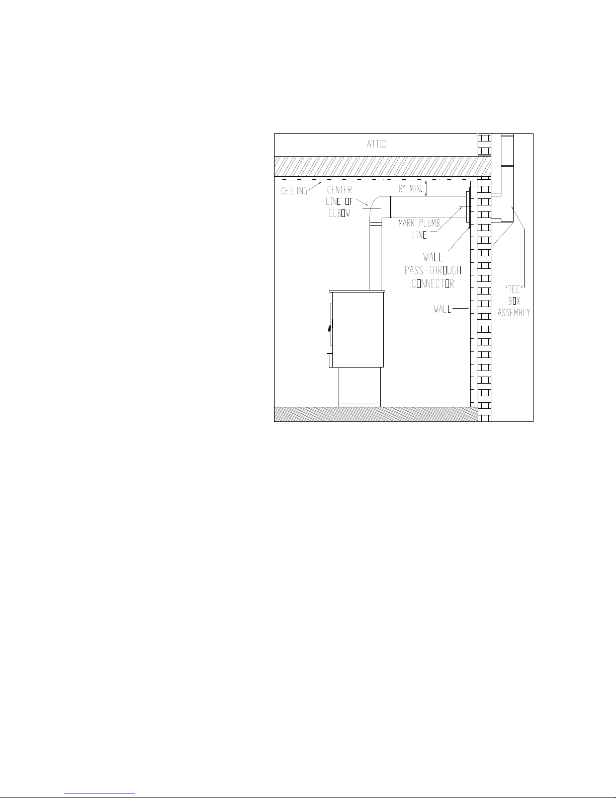
3. Now connect stove to ceiling support box by using #24 ga. minimum blued or black steel chimney pipe. (Do
not use galvanized pipe.) Connect each section so crimpled end faces downward, and secure each section to
each other using at least three (3) sheet metal screws or rivets. (See Figure 8)
Wall Exit Into Metal Tee-Box
1. Mark the plumb line on the wall directly behind center of heater. (See
Figure 9)
NOTE: When using #24 ga. min. blue or
black steel pipe, maintain 18" between
pipe and ceiling.
2. Place vertical portion of heater pipe
and elbow in position and project a
point onto plumb line level with the
center of elbow.
3. Measure up so there will be at least
1/4" rise per foot of horizontal
connector pipe, maintaining
clearances to ceiling as noted in
Figure 10. This will give you center
of hole for chimney penetration.
4. After locating center of penetration,
install tee-box and chimney as per
chimney manufacturers' specifications
and local building codes for
installation through combustible walls
or ceilings.
5. Connect chimney collar to tee-box using #24 ga. minimum blued or black steel connector pipe. DO NOT USE
GALVANIZED PIPE. Connect each section so the crimped end faces downward, and secure each section to
each other using at least three steel sheet metal screws or rivets.
*B
FIGURE 9
Wall Exit Into Masonry (using single wall pipe)
1. Before connecting the Model 80 to a masonry chimney, determine that masonry fireplace wall pass-through
connector thimble meets the NFPA-211 Code and local building codes and is a minimum of 18" from ceiling.
If connector thimble does not meet these codes, the pass-through connector must be modified. Connectors may
pass through walls or partitions constructed of combustible material if connector is:
(a) either listed for wall pass-through or is routed through a device listed for wall pass-through and is
installed in accordance with conditions of the listing.
(b) selected or fabricated in accordance with conditions and clearances as stated in tables 5-7 of the 1988
NFPA 211 Code. Any unexposed metal that is used as part of a wall pass-through system and is exposed
to flue gases shall be constructed of stainless steel or other equivalent material that will resist corrosion,
softening, or cracking from flue gases at temperatures up to 1800oF.
In addition, a connector to a masonry chimney shall extend through the wall to inner face or liner but not beyond,
and shall be firmly cemented to masonry.
EXCEPTION: A thimble may be used to facilitate removal of chimney connector for cleaning, in which case
thimble shall be permanently cemented in place with high-temperature cement.
Page 15
Page 18
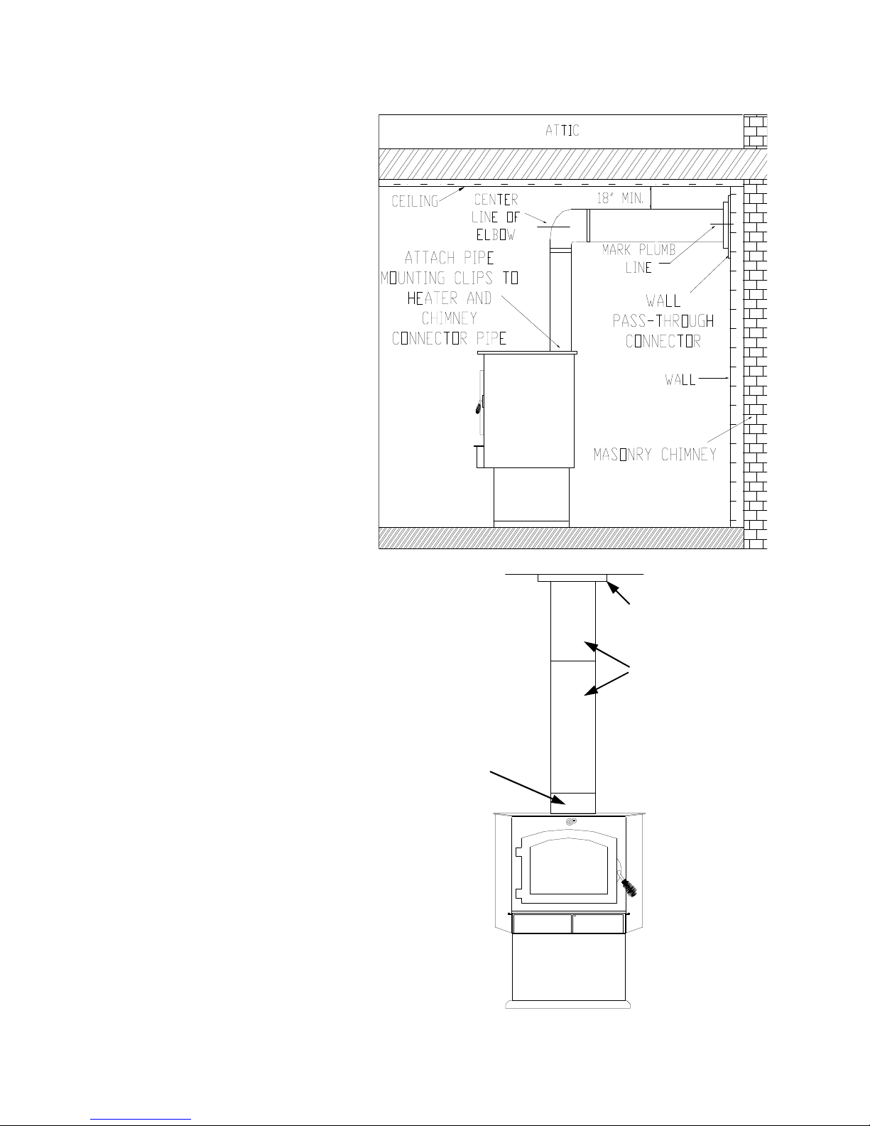
2. Once through-the-wall thimble
codes are met, simply connect
chimney pipe to wall pass-through
connector using #24 ga. minimum,
blued or black steel pipe as follows:
(a) Maintain 1/4" rise per foot
(horizontal length) from
appliance to the chimney.
(b) Each section of pipe should fit
into section below or into the
opening on stove, for drip free
operation.
(c) Secure each section to each
other using at least three (3)
sheet metal screws or rivets.
(d) Use three (3) screws to connect
pipe to New Buck Corp.
Chimney Connector.
Ceiling Exit—Close Clearance
1. Suspend a plumb bob from ceiling
above unit so that weight is
hanging in center of lue exit. (A
small weight on a string will serve
as a plumb bob.) Mark ceiling
where string is suspended to locate
the center of chimney hole.
2. After locating center of hole, install
the ceiling support box, chimney or
chimney connector, flashing, and
rain cap.
3. Next, install a New Buck Corp.
Chimney Connector to flue of
heater.
4. Install Double Wall Connector and
chimney system per manufacturer’s
list of tested pipes
Caution: Because of high efficiency
and low flue gas temperature,
freestanding catalytic heaters connected
to masonry chimneys with oversized
flue lines may encounter drafting
problems.
FIGURE 10
CEILING SUPPORT
BOX
SINGLE WALL
PIPE
BUCK STOVE
CHIMNEY CONNECTOR
FIGURE 11
Page 16
Page 19
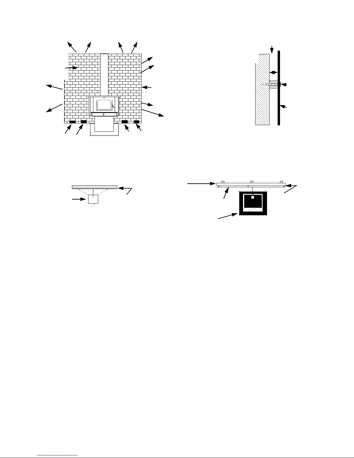
AIRSPACE
BRICK
CLEARANCE
REDUCTION
SYSTEM
LEAVE 1 INCH
CLEARANCE FOR AIR
CIRCULATION
BRICK WALLS MAY BE ATTACHED TO COMBUSTIBLE WALLS
USING WALL TIES. IF BRICK IS USED, BE SURE FLOOR CAN
WITHSTAND THE WEIGHT OF THE BRICK.
COMBUSTIBLE WALL
WOOD STOVE
FLOOR
CLEARANCE REDUCTION SYSTEM
SPACED OUT 1
INCH.
AIR CIRCULATION
BRICK WALL SPACED
OUT 1 INCH FROM
PROTECTED SURFACE
1 INCH NON-COMBUSTIBLE SPACER SUCH AS STACKED WASHERS, SMALL DIAMETER PIPE, TUBING, OR ELECTRICAL CONDUIT.
COMBUSTIBLE
WALL
FLOOR PROTECTOR
FIGURE 12
COMBUSTIBLE
WALL
1”
NAIL OR
SCREW
ANCHOR
MINIMUM
24 GAUGE
SHEET
METAL
DO NOT USE FASTENERS DIRECTLY BEHIND CHIMNEY CONNECTOR OR STOVE
TOP VIEW
MINIMUM
24 GAUGE
SHEET METAL
SHEET METAL CLEARANCE REDUCTION SYSTEM
NON-COMBUSTIBLE
SPACERS
ALTERNATIVES FOR WALL PROTECTION
Example: The rear clearance for the Model 80 from page 12 is 26". (Measurement A.) This clearance may be
reduced by 66% by using either of the wall protection devices mentioned below.
Tested and Listed Wall Protector
Clearances to combustibles may be reduced if a tested and listed wall protector is installed over a combustible
surface when the following condition exist:
1. A dead air space or 1" separates the listed and tested wall protector from the combustible surface.
2. The tested and listed wall protector extends from floor to ceiling with a 1" clearance for air circulation at both
the floor and ceiling.
3. The 1" spacers (preferable ceramic rather than metal) must be located at the corners rather than behind the
heater or the chimney connector.
Unlisted and Untested Wall Protector
Wall protectors may be constructed of masonry, 24 gauge or thicker sheet metal, or non-combustible 1/2" thick
insulation board. Conditions 2 and 3 above must be observed but the air space in condition 1 must be increased to 1
1/2".
FINAL CHECK
1. Recheck specified clearances.
2. Remove all foreign material from firebox area.
Page 17
Page 20

3. Open primary air drafts and damper bypass.
4. Plug power cord into a 115 VAC outlet.
5. Place crumpled pieces of newspaper in stove. Light and close door. Make sure that stove draws properly
through primary drafts.
6. Check for smoke leaks around door.
7. Open door and check for smoke escaping from front of stove. Smoking usually indicates a defective or poorly
positioned chimney. Some chimneys with a marginal draft can be preheated by lighting newspaper and
holding it near open damper with a poker or fire tong. Once chimney heats up, a proper draft can usually be
obtained.
If a thorough review of Troubleshooting Guide in the rear of the manual does not reveal your problem, contact
your dealer for assistance.
NOTE: The unit is painted with a specially formulated high temperature paint that cures during first two or three
firings. You may notice a slight smoking effect and an odor of burning paint when you build the first fires. This is
normal and is not a cause for alarm. In some cases, these fumes will activate a smoke alarm. Opening a window
near unit will allow these fumes to escape. DO NOT build a large, roaring fire until this curing is complete or the
heater finish may be damaged.
Page 18
Page 21

SECTION IV
WOOD HEATER SAFETY
Certain safety hazards are inherent in any wood heater installation. You should be aware of these so that a safe and
proper installation can be made.
1. FAULTY CHIMNEY: An older masonry chimney should be thoroughly checked to be sure there are no
holes or weak spots which could allow sparks or hot gases to escape.
2. HEAT CONDUCTION: Placing combustible materials too close to a heater or chimney can be a fire hazard.
By keeping these particular hazards in mind as you install and use your room heater you can ensure a safe, reliable
installation.
NOTE: When burning any unit or appliance that combusts fuel for heat, such as coal, oil, wood or
natural and (L.P.) liquid petroleum gas. We highly recommend the use of smoke and carbon
monoxide detectors in your home.
The connector and/or chimney should be inspected at least once a month during heating season to determine if a
creosote buildup has occurred. Any buildup of soot should be removed to prevent risk of a chimney fire. To
remove chimney or chimney connector, remove screws and/or fasteners. Remove pipe and clean with a steel wire
brush. Replace chimney or chimney connector and replace screws and/or fasteners.
CAUTION: NEVER use gasoline, gasoline-type lantern fuel, kerosene, charcoal lighter fluid or similar
liquids to start or “freshen up” a fire in heater. Keep all such liquids well away from stove when it is in use. All
fluids of this type give off volatile fumes and can and WILL EXPLODE!! Don’t take a chance with the safety of
your home and family.
WARNING: Hot while in operation. Keep children, clothing and furniture away from stove. Contact may cause
skin burns.
HELPFULHINTS
CURING THE PAINT ON YOUR HEATER: During the first several firings, burn small fires to cure paint and
to prevent damage to finish. It is a good idea to flip the toggle switch to “Manual” position during these first firings
so the blower will run continuously. This will allow the paint to cure at a slower rate and creates a better overall
finish.
CAUTION: Never remove ashes from your heater with blower running.
TIPS ON FIRE BURNING
GREEN WOOD vs. NATURAL SEASONED HARD WOOD-Green wood has a high moisture content and
therefore requires a hotter ignition temperature. Seasoned wood-cut at least one year before use-allows for a
quicker, prolonged burn and more complete combustion.
SPLIT WOOD vs. ROUND WOOD-Split wood burns easier and more rapidly, whether it’s seasoned or
green. If used after starting a fire, it should be packed tightly to achieve a longer burn.
Round wood burns longer, but requires more effort to start. Inserting a round piece over a bed of red coals
with the damper and drafts open will help it catch fire. Round wood should be used to accomplish an allnight burn.
Page 19
Page 22

SECTION V
OPERATION
This section of the manual is to help you get maximum efficiency and maximum smoke (particulate) reduction
from your Model 80 heater. If you should experience any difficulty or have questions concerning your heater,
contact your Model 80 dealer for assistance.
Manufacturer recommendation for peak performance and long catalyst life is to burn seasoned hardwood
(wood dried 6-12 months) and place wood from front to back position in the heater.
NOTE: Soft woods such as pine, create more creosote, clogging of chimney, and produce a less
efficient burn performance.
Build a fire for maximum efficiency. Model 80 burns wood and extracts heat so efficiently a large fire is not
necessary. A large fire not only wastes energy, it usually results in the home being too warm for comfort. The
following steps will serve as a guide for operating your stove.
GUIDE TO THE DIFFERENT BURNING QUALITIES OFWOOD
Type of Ease of Coaling Amount of
Wood Starting Qualities Sparks
Apple Poor Excellent Few
Ash Fair Good Few
Beech Poor Good Few
Birch Good Excellent Moderate
Cherry Poor Excellent Few
Cedar Excellent Poor Many
Elm Fair Good Very Few
Hemlock Good Low Many
Hickory Fair Excellent Moderate
Locust Poor Excellent Very Few
Maple Poor Excellent Few
Oak Poor Excellent Few
Pine Excellent Poor Moderate
The Main Audubon Society recently charted the heat produced by a wood fire. They noted that the heat produced
by a wood fire varies greatly with the kind of wood burned. Beech is considered the best wood for a fire. A cord of
well-seasoned Beech will produce as much heat as 169 gallons of fuel oil; Sugar Maple and Red Oak produce as
much heat as 166 gallons of fuel oil; followed by White Ash 154; American Elm 130; White Birch 124; and White
Pine 94.
Page 20
Page 23

BUILDING A FIRE:
1. Place the “Manual/Off/Automatic” switch in “Automatic” position for thermostat control operation. Turn
rheostat knob clockwise (it will click from “Off” position to “On”) so you can vary the speed of motor.
2. Open door.
3. While looking inside firebox, operate damper bypass plate in and out observing the movement. This should
operate freely and close completely. Open damper bypass.
4. Open the air controls on each side of stove (pull out).
5. Twist 4 or 5 pieces of non-colored newspaper in a roll and place on floor of the firebox.
The Model 80 Bay is not designed for use with grates, andirons or other methods of supporting fuel.
NOTE: “Do not use grate or elevate fire. Build wood fire directly on inner bottom of fire box.”
3. Lay several pieces of dry kindling on top of newspaper.
4. Place three or four small pieces of firewood, 2-3" in diameter, on top of kindling.
5. Light newspaper, close and latch door. Don’t leave fire unattended at this point. The draft should start
quickly. If not, it may be necessary to preheat the chimney to get draft started. To do this, open the door and
add newspaper to top rear of wood. Light or let this paper ignite and allow to burn while holding door
slightly open. Do not leave stove unattended with door open! Once draft has started, close and lock door. A
direct connect (option) usually solves this problem. Check with your dealer.
6. After embers and a coal bed have been established, load heater with natural seasoned hard wood, placing it
from front to rear. DO NOT BUILD A LARGE ROARING FIRE! Initially, build 2-3 small fires in order to
cure the paint on your stove.
7. Within the 20 minute time frame, you can begin to add your wood. Remember—DO NOT FILL firebox
during your first 2 to 3 fires!
8. Once your fire is burning well, and probe reached 600º close the bypass damper (push in). Gradually close
the primary air controls (push in). You will have to experiment with primary air controls to accommodate
your draft. If you close them too soon, your fire may die down too quickly and go out. Close them gradually,
a little at a time, until you can close completely.
NOTE: If optional blower is being used on the Model 80. Your stove is equipped with a automatic
thermostat. When stove gets hot enough, thermostat will activate the room air blower. Set
fan speed according to desired heat output.
NOTE: When refueling or removing ashes turn “OFF” room air blower. Be sure to turn room air blower
back on when finished.
NOTE: Do not run power cord underneath heater or in walk way or heavy traffic areas.
NOTE: THE FUELING DOOR MUST REMAIN CLOSED DURING OPERATION.
BURN RATES
A. Low Burn Rate: Set primary air controls (both) almost closed - leave open about 1/8". Set the rheostat
for fan control between the low to medium speed. This burn rate is the most desired and most efficient,
but can only be achieved after a fire has been established and burning on its own controlled air. Close
bypass damper (push in).
B. Medium-Low Burn Rate: Partially close primary air controls (push halfway in). Close bypass damper
(push in). Set rheostat for fan control halfway between low and high.
C. Medium-High Burn Rate: Set primary air controls almost fully open. Close the bypass damper. Set
rheostat for fan control between medium position and high position.
D. High Burn Rate: Set primary air controls wide open. Have damper closed. Set rheostat for fan control
all the way on high. USE CAUTION! Close shotgun air control after 5 minutes.
E. Wood Loading: During refueling, open (pull out) bypass damper to allow smoke in the firebox to escape
- wait a few seconds, slowly add wood. Immediately close door and bypass damper. Open primary air
control wide open for 2 minutes to charge wood. After most of wood has burned and if you are not
planning on reloading immediately, it may be necessary to open damper bypass, then door and rake wood
and coals into a pile near the front center of firebox. (Be certain wood chunks are pulled out of rear
corners.) Close door and damper bypass. This step will assure continued combustion and thorough
burning of the wood.
You will have to experiment with fire rate until you find the particular setting for heating your home. Chimney
drafts, tightness of house, doors, windows, insulation in house and atmospheric conditions all influence which
setting you must have, so it may take several firings to learn the setting necessary for your installation. Heating
capacity is based on BTU output and the conditions listed above. These conditions will affect the heating capability
of your heater.
Although the catalytic stoves decrease ash residue, routine removal of excess ash is still necessary.
Page 21
Page 24

SECTION VI
PREVENTIVE MAINTENANCE / PARTS REPLACEMENT
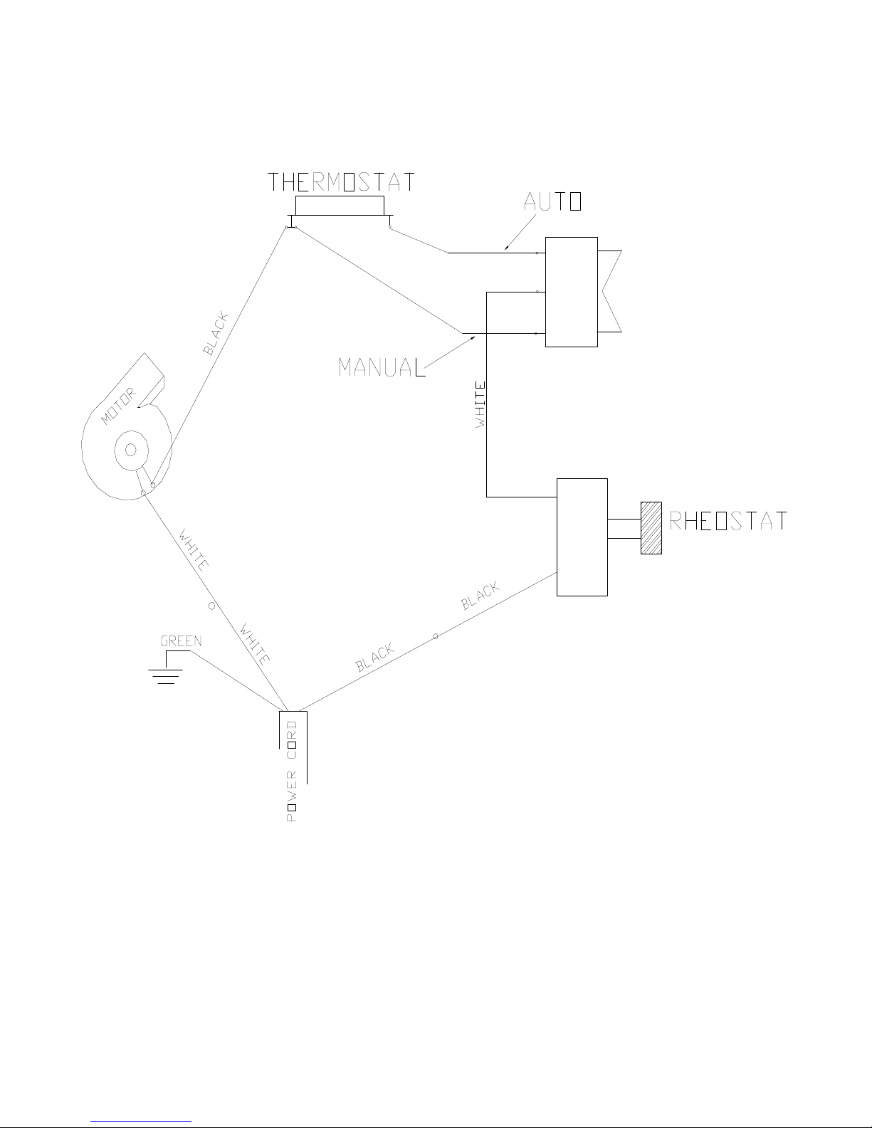
Disassembly Inspection and Catalytic Replacement
The catalysts in your stove are designed for many years of use. If after several years of use, the efficiency of stove
decreases or if a notable amount of smoke is observed, the catalysts may need to be replaced. See Catalyst
Warranty prior to replacement.
CATALYST REPLACEMENT (Off-Season Replacement Recommended)
1. Spread a drop cloth in front of stove.
2. Open door and clean out any ash.
3. Using penetrating oil, generously lubricate the four (4) bolt threads holding catalyst housing in place. Allow to
penetrate.
4. Using a 9/16" wrench or 9/16" socket, loosen the four (4) nuts and remove catalyst housing (drop down) and
place in a suitable work area.
5. Using needle nose pliers, grasp the front edge of the stainless steel “can” which houses the catalytic element
and pull upward. Reposition pliers to another position and pull upward. Repeat procedure until catalyst can be
removed from housing.
6. Using a small putty knife or scraper, remove any gasket that may have adhered to catalyst housing.
7. Now, obtain new catalyst and wrap the stainless steel can with interam gasket and tape ends together using
scotch tape or masking tape.
8. Insert new catalyst into catalytic housing and push down until they are seated on top of stainless steel wire
mesh supports.
9. Reinstall catalyst housing into stove and secure in place with bolts.
10. The stove is now ready for use.
GASKET REPLACEMENT (Cold Heater)
To replace deteriorated gaskets, the following steps must be taken to ensure proper installation:
1. Obtain proper gaskets and silicone glue from your local dealer.
2. Using pliers, remove any worn and deteriorated gaskets.
3. Using a scraper, wire brush and sand paper or steel wool, clean glue and gasket residue from door frame.
4. Measure and cut gaskets to length. Care should be taken not to stretch gaskets. What you want is a full and
loose gasket weave after attached to framing.
5. Obtain the silicone glue and run a 3/16" bead inside the door frame.
6. Obtain gasket(s) and place in gasket channel areas. Use a technique which assures that gasket is applied in a
loose like manner. DO NOT STRETCH GASKETS.
7. After gasket(s) are applied to glue, use your finger and go over all the gasket gently pressing gasket to
channel. Use same pressure against gasket so that final result is an evenly applied gasket.
8. Leave door open and allow at least one hour for glue to dry.
9. Once gaskets are checked, heater is ready for use.
Page 22
Page 25
Page 23
Page 26

SECTION IV
TROUBLESHOOTING
Operation of any wood heater can create problems. While use of a catalytic-combustor equipped stove will
substantially lessen some of these problems-such as creosote formation-other traditional wood heater problems
may remain.
The following guidelines apply to operation of all wood heaters with problems related to catalytic heater addressed
where appropriate.
HEATER RELATED PROBLEMS
Problem
1. Sluggish Heater Performance
2. High Fuel Consumption
Possible Cause
1. Obstruction in chimney
2. Improperly sealed trim kit or
direct connect kit
3. Manual damper in chimney is
closed
4. Closing bypass or exhaust
damper too soon
5. Poor chimney draft
6. Combustor is plugged
7. Wet or unseasoned wood
being burned
1. Inexperience in catalytic
operation
2. Improper Regulation of draft
or inlet air
3. Improper Door Fitting
4. Combustor not engaged
Solution
1. Check for and remove
obstruction
2. Check trim kit gasketing or
direct connect kit seal to
fireplace and gasket as
necessary to seal unit. Gasket
under stove if needed. Check
seal of direct connect and
correct
3. Open manual damper and
wire shut with stainless steel
wire or remove damper
4. Follow New Buck
instructions for proper firing
procedures
5. Improper chimney height or
wrong size flue being used.
Cooler temperatures caused
by external chimney.
6. See section in “Combustor
Related Problems”
7. Burn dried natural seasoned
hard wood
1. Operate stove with desired
heat output in mind. Do not
be overly concerned with
maintaining light-off
temperatures
2. Close inlet air control as
much as possible to maintain
desired heat output. Check
gaskets. Reinstall fiberglass
gasketing around doors and
glass as necessary
3. Check door gasket. Check
adjustment of door latch.
4. Put combustor in operating
position in retrofit or close
bypass damper in stove
Page 24
Page 27

Problem
3. Backpuffing
Possible Cause
1. Gusts of wind
2. Hot combustor
(Above 1400oF)
Solution
1. Install Buck draft inducer
2. Increase the amount of
combustion air slowly.
4. Smoke Rollout when heater
door is opened
5. Low Catalytic Temperature
1. Bypass damper is closed, or
combustor is in operating
position
2. Wind gusts blowing down
chimney
3. Opening heater door too fast
1. Bypass damper is open
2. Light-off not obtained
3. Fuel charge is spent
4. Combustor coated with fly ash
or soot
5. Heater dampered down too
much
1. Open bypass damper. In
retrofit place combustor in
bypass position before
opening stove door
2. Install Buck draft inducer
3. Wait a few seconds after
opening bypass damper before opening heater door to
give smoke a chance to exit
heater
1. Once light-off temperatures
have been reached and unit is
stabilized, close bypass
damper
2. Follow manufacturer’s operating instructions
3. Refuel as necessary for combustor operation
4. See section on “Combustor
Related Problems”
5. Ensure that proper air mixture and draft are available
for wood pyrolysis to continue
COMBUSTOR-RELATED PROBLEMS
1. Plugging
1. Burning materials that produce
2. Burning wet, pitchy wood or
2. Catalyst Peeling
3. Catalyst Masking
1. Extreme temperatures at
1. Not maintaining light-off
a lot of char and fly ash
burning large loads of smalldiameter wood with the
combustor in the operating
position without light-off
taking place
combustor surface can cause
the catalyst to peel. Overfiring and flame impingement
are primary cause
temperature
1. Do not burn materials such as
garbage, gift wrap or
cardboard
2. Burn dried natural seasoned
hard wood. Don’t place the
combustor in the operating
position until high
temperatures are high enough
to initiate light-off. It may be
possible to burn the
accumulated soot or creosote
off by putting the combustor
in a partially open-partially
closed position after a “hot”
fire has been started
3. If peeling is severe, remove
and replace combustor Avoid
extreme temperatures.
1. Place combustor in a partially
closed position after a “hot”
fire has been started to burn
soot off
Page 25
Page 28

NEW BUCK CORPORATION (NBC)
“LIMITED WARRANTY” FOR NBC RELATED PRODUCTS
PLEASE READ THIS WARRANTY CAREFULLY
PRODUCTS COVERED
This warranty covers the new heating unit so long as it
is owned by the original purchaser, including optional
and standard accessories purchased at the same time,
subject to terms, limitations and conditions herein set
out.
PRODUCTS NOT COVERED
This warranty does not cover the following:
Glass, Refractory material or firebrick, Gaskets.
This Warranty will not cover any damage and/or
failure caused by abuse or improper installation of the
Products Covered.
WARRANTY TIME PERIODS
(A) Period I
For one (1) year from the date of purchase, NBC will
replace or repair, at its option, any part defective in
materials or workmanship. The costs of parts only are
included. The customer pays any labor or transportation
charges required.
Thereafter
(B) Period II
For period after first year from date of purchase and
extending for five (5) years as long as related product is
owned by original purchaser, NBC will repair or
replace, at its option, any part defective in materials or
workmanship, with the exception of: electrical motors,
wiring, switches and components; optional and standard
accessories; and all parts not permanently attached to
heating unit. Parts not permanently attached to heating
unit are defined as those items designed to be removed
from unit, including those removable with common
hand tools. The cost of parts only are included. The
customer pays any labor or transportation charges
required.
PROCEDURE
Should you feel that your heater is defective, you
should contact any NBC dealer for the name of your
nearest authorized heater service representative, who
will instruct you on proper procedure, depending on
which Warranty Time Period (Period I or Period II)
applies.
If for any reason you are dissatisfied with suggested
procedures, you may contact us in writing at:
NEW BUCK CORPORATION
Customer Service Department
P. O. Box 69
Spruce Pine, NC 28777
CONDITIONS AND EXCLUSIONS
(A) Replacement of parts may be in the form of new
or fully reconditioned parts, at NBC’s option.
(B) There are no other warranties express or implied
including warranties of Merchantability, Fitness
for Purpose or Otherwise except those warranties
expressly stated herein.
(C) New Buck Corporation is not liable for indirect,
incidental, or consequential damages in
connection with use of product including any
cost or expense or providing substitute
equipment or service during periods of malfunction or non-use. Some states do not allow
exclusion of incidental or consequential
damages, so the above exclusion may not apply
to you.
(D) All warranty repairs under this warranty must be
performed by an authorized Buck Stove service
representative. Repairs or attempted repairs by
anyone other than an authorized service
representative are not covered under this
warranty. In addition, these unauthorized repairs
may result in additional malfunctions, the
correction of which is not covered by warranty.
OTHER RIGHTS
This warranty gives you specific legal rights, and you
may also have other rights, which vary from state to
state.
OWNER REGISTRATION CARD
The attached Owner Registration Card must be
completed in its entirety and mailed within 30 days
from the date of purchase or from the date of
installation, if installed by a factory certified installer,
to New Buck Corporation, in order for warranty
coverage to begin.
PLEASE NOTE: The Owner Registration Card must
contain the Authorized Dealer Code Number and the
Certified Installer’s number (if applicable) for
warranty coverage to begin.
Page 26
Page 29

To be completed by selling distributor or dealer for customer:
OWNER REGISTRATION CARD
Name
(Last) (First)
Address
City State Zip
CUSTOMER EMAIL::_________________________________________________________
Model 80 Insert: Residential
Model 80 Freestanding: Residential
Serial No.
Date of Installation: Day Month Year
Installer’s Name Certification No.
Dealer Name
City State
Dealer No.
Distributor Name
Distributor No.
Is appliance customer self-installed? Yes No
Has appliance been completely checked out? Yes No
Has customer been given appliance and operation orientation? Yes No
a) Damper/Door Vents g) Chimney Safety
b) Door-Handle h) Rain Cap
c) Thermostat-Normal Operation i) Wood Preparation
d) Hot Surface Area j) Installation
e) Speed Control k) Instructions &
f) Paint-Curing Clearances -
Self-Installation
Has customer been given WARRANTY REVIEW? Yes No
CUSTOMER SIGNATURE
New Buck Review
DATE
Mail to:
NEW BUCK CORPORATION
200 Ethan Allen Dr.
P.O. Box 69
Spruce Pine, NC 28777
Page 27
Page 30

 Loading...