

Page 1

MANUFACTURERS OF SPECIALIST TEST EQUIPMENT
Wet Roof Pro’
Operating Instructions
English Version
Please read carefully before use
Page 2

Page 3

Wet Roof Pro’
3
Contents
Page
General Description 4
Technical Specification 5
Unpacking 6
Safety Precautions and Symbols 6
Controls and Connections 7
Generator 7
Detector 10
Battery charger 13
Operation Principle 19
Using the Wet Roof Pro’ 21
Preparation 21
Surveying 23
Maintenance 25
Disposal Information 25
EC Declaration of Conformity 26
Contact Details 27
Distributor Details 27
Page 4

Instruction Manual
4
General
Description
The Wet Roof Pro’ leak detector compliments the existing range of
Buckleys Dry Roof Pro’ test instrument to provide a complete roof test
system for all occasions. The Wet Roof Pro’ has been designed as an
aid to identifying the source of leaks on roofing technologies that
incorporate dielectric membrane overlays. With large easy to read
graphics displays and user-friendly icons enabling fast accurate roof
surveys to be undertaken.
The Wet Roof Pro’ leak detector kit comprises two main elements:
A ‘generator unit’ which provides stabilised low frequency pulses. The
negative output is applied to a trace wire bordering the test area and
the positive output is connected to a suitable earthed point of the
building’s substrate. Within the test area - if moisture has penetrated
the roofing membrane - electrical current will flow from the trace wire
towards the source of the leak; via the moisture on the roof.
By conducting a systematic survey of the roof test area the operator is
guided by the detector unit toward the origin of the leak. The leak origin
is the fault or point of failure within the roof membrane where moisture
has penetrated.
The hand-held survey poles connect to the detector unit allowing for
precise location of the leak origin. Both generator and detector units
are powered by operator replaceable batteries, either standard
disposable alkaline batteries or rechargeable cells which can be
charged using the battery charger supplied. The battery charger also
has an in-car adaptor to allow charging of batteries whilst travelling
between sites.
Attention! The charger is only suitable for recharging nickelcadmium (NiCd) or nickel-metal hydride (NiMH) cells. Non
rechargeable batteries or other types could cause an
explosion. Do not attempt to charge zinc/alkaline batteries
or other types of non-rechargeable, primary batteries.
Page 5

Wet Roof Pro’
5
Technical
Specification
Generator
Output pulse voltage: 32 V DC Output
pulse frequency: 0.25Hz or 0.5Hz
Output power: <10 Watts
Operating temperature: + 4˚ to + 40˚C
Dimensions (L x H x D): 169 x 80 x 235 mm
Weight: 2.1 kg – including batteries
Protection: Sealed to IP65 rating
Relative humidity: Maximum 80% non-condensing
Detector
Operating temperature: + 4˚ to + 40˚C
Dimensions (L x H x D): 189 x 37 x 138 mm
Weight: 580g – including batteries
Protection: Sealed to IP65 rating
Relative humidity: Maximum 80% non-condensing
Battery charger
Input voltage (In-car): 12V - 16V DC
Input voltage (Mains): 100V - 240V AC
Output voltage: 4 x 1.45V and 2 x 10.15V
Accessories
Survey pole length: 3 Section - 1000mm
Trace wire: 200m stainless steel
Transit case weight: 17.5Kg (full kit with accessories)
Interconnecting leads: 1 x 10m, red plug - substrate
1 x 10m, black plug - trace wire
1 x 1m, red plug - right survey pole
1 x 1m, black plug - left survey pole
Page 6
Instruction Manual
6
Unpacking
The Buckleys Wet Roof Pro’ leak detector kit and all associated items
necessary to conduct a roof survey are supplied in a robust transit case.
Retain all outer packaging to re-use in future should you need to store or
return the Wet Roof Pro’ for servicing. Please note any damage to the outer
packaging before checking the kit contents.
When first unpacking the Wet Roof Pro’ kit carefully check each item and
report any missing or damaged items. The full kit comprises the following
items;
● 1 x Generator unit
● 1 x Detector unit in protective neck pouch
● 1 x Battery charger with mains and in-car adaptors
● 1 x 200m trace wire on reel
● 1 x Substrate connection lead (red plug)
● 1 x Trace wire connection lead (black plug)
● 1 x Hooked seam tool
● 2 x Survey poles (3 sections to each pole)
● 2 x Yellow wax crayon (for marking defects)
● 4 x ‘D’ cell batteries (Generator)
● 4 x ‘AA’ cell batteries (Detector)
Safety precautions and symbols
This symbol denotes important information on potential
hazards. Please read these sections with particular care.
Attention! Misuse or failure to comply with the guidelines
outlined in this manual may impair the safety provided by
the equipment.
Page 7
Wet Roof Pro’
7
Controls and
Connections
Generator
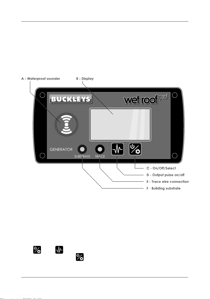
The Wet Roof Pro’ generator unit is housed in a robust waterproof closure
with all connections and controls mounted on the front panel.
Fig. 1 details the Generator front panel controls and connections.
Fig.1 Generator front panel controls
The graphics display [B] displays two lines of information. The upper
line concerns the generators pulse functions and comprises pulse
icon, frequency/duration and alarm activity. The lower line shows
battery status, output voltage, the electrical current drawn by the roof
membrane and button indicator icons.
Both and buttons (items C & D – fig: 1) are dual function. A
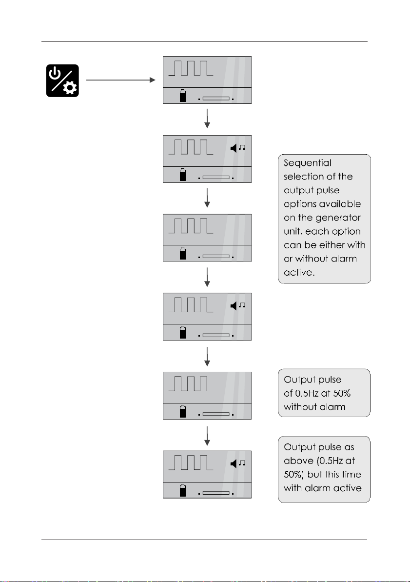
single short press of the activates the generator unit, subsequent
short presses step through the various pulse and alarm options (see
fig. 3).
O/I
Select
Pulse
Page 8
Instruction Manual
8
To switch the generator unit off press and hold the button for longer
than two seconds.
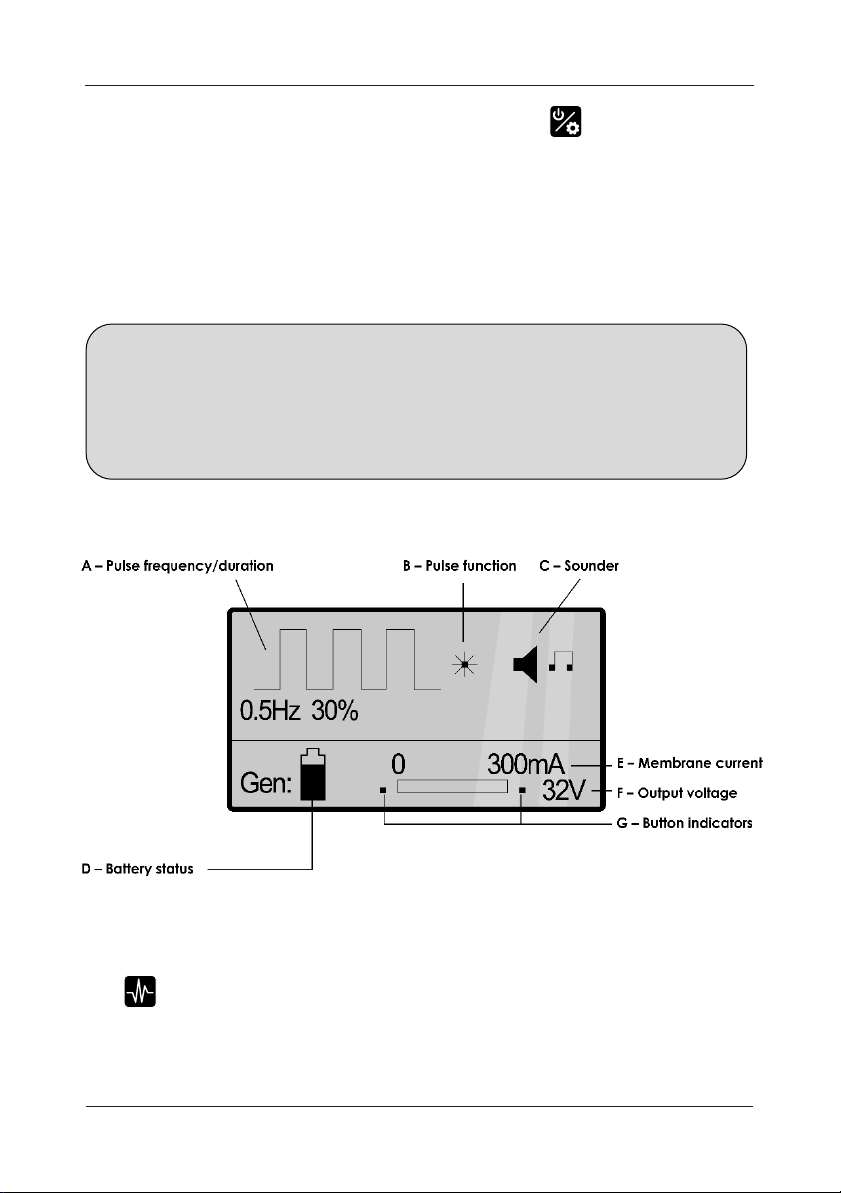
Fig. 2 (below), details the generator graphics display. The pulse
frequency and pulse duration can be stepped through three separate
settings, these are 0.25Hz at 30% duration, 0.50Hz at 30% duration and
0.50Hz at 50% duration. Each pulse function can either be with or without
the sounder active, giving six possible combinations.
NOTE: Hz is the international symbol for frequency. A 0.5Hz pulse
equals 2 seconds, while 30% refers to an ‘ON’ time (voltage present at
the output sockets). Therefore, 30% of 2 seconds gives an ‘ON’ time of
0.6 seconds and 1.4 seconds ‘OFF’. The sounder will alarm during the
‘ON’ period if it has been selected.
Fig.2 Generator display icons
The button (item D – fig.1) sets the output voltage pulsing
at the
frequency and duration selected. Whenever the output voltage is
present (on) the pulse function icon (item B – fig. 2) is highlighted,
changing state from plan square to radiating square.
Page 9
Wet Roof Pro’
9
Fig.3 Pulse sequence options
Page 10
Instruction Manual
10
Detector
The Wet Roof Pro’ detector, housed in a waterproof enclosure has been
designed to be worn around the operator’s neck thereby leaving both
hands free to complete the roof survey.
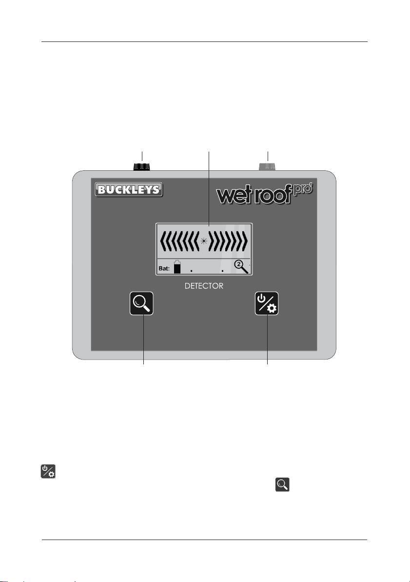
Detector controls and connections are shown fig. 4.
A – Left-hand survey pole
B – Graphics display C – Right-hand survey pole
BUCKLEYS
Wet Roof Pro’
MAG:
Detector
O/I
SELECT
D - Magnification button E - On/Off/Select button
Fig.4 Detector unit
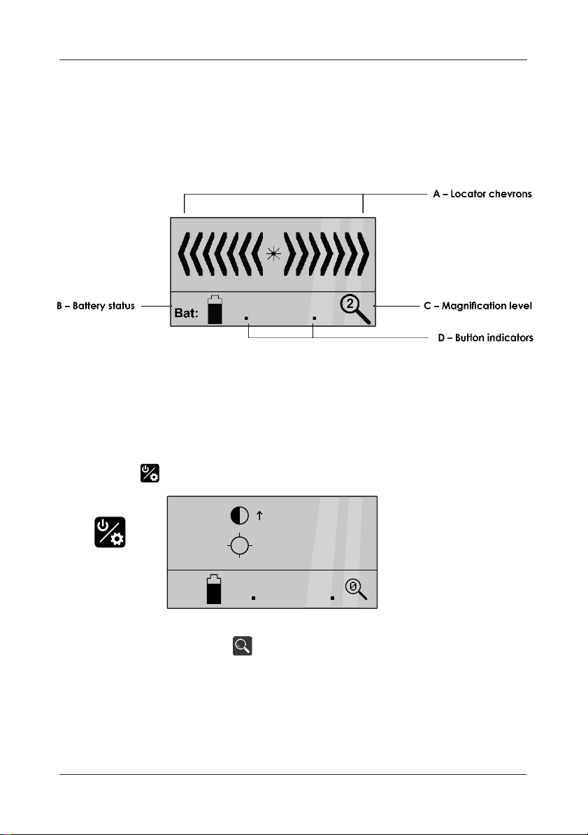
The detector’s graphics display is similar to that of the generator unit.
The upper line displays left and right direction chevrons with the lower line
showing battery status, magnification setting and button indication icons.
Both detector buttons are also dual function. A single short press of the
button switches the detector unit on. The detector has three
magnification (sensitivity) levels. Short presses of the button step
through the available levels with the selected setting displayed on the
lower line (see fig. 5). The higher the magnification setting, the more
sensitive the detector’s response.
Page 11
Wet Roof Pro’
11
The black and red 4mm sockets (items A & C respectively – fig. 4
connect to the colour matched survey poles (left pole = black, right pole
= red) using the two short 1m leads supplied with the Wet Roof Pro’ kit.
Four 1.5 volt ‘AA’ style batteries power the detector unit, these are
located in the battery compartment at the rear of the unit.
Fig.5 Detector display
Brightness/contrast adjustment
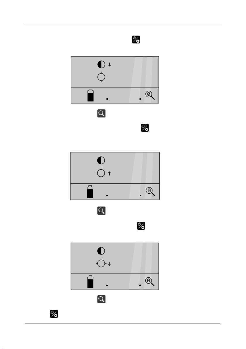
Once the detector unit has completed its start-up sequence, adjustments
to the brightness/contrast of the detector’s display can be made by briefly
pressing the button to open the brightness/contrast control:
Subsequent presses of the button will increase the display’s contrast.
(< 1 second)
=
Page 12
Instruction Manual
12
To reduce the contrast, briefly press the again and the vertical arrow
next to the contrast icon will invert:
Subsequent presses of the button will reduce the display’s contrast.
To increase the brightness, briefly press the button again and the
vertical arrow next to the contrast icon will invert and move down to the
brightness icon:
Subsequent presses of the button will increase the display’s brightness.
To reduce the brightness, briefly press the button again and the
vertical arrow next to the brightness icon will invert:
Subsequent presses of the button will reduce the display’s brightness.
Press the button to return to the detector’s idle screen.
Page 13

Wet Roof Pro’
13
Battery charger
Safety
• Please read these operating instructions carefully before using the charger.
• Do not use the device if there are any signs of damage to the housing, plug
or cable. If you do find any damage to the unit, please contact an
authorised dealer.
• Use only with NiMH/NiCd cells. Other battery types may explode;
• Please make sure batteries have been inserted with the correct polarity (+/-)
prior to use.
• Please note that due to the high charging current, only high quality brand
rechargeable batteries should be charged with this device. Low quality cells
may leak and damage the charger and invalidate the warranty.
• Keep the charger in a dry place away from direct sunlight;
• To avoid the risk of fire and/or electric shock, the charger must be protected
against high humidity and water.
• To clean the unit, disconnect the power supply and only use a dry cloth.
• Never attempt to open the charger.
• Keep out of the reach of children. Children should be supervised to ensure
that they do not play with the charger.
• The device is not to be used by children or people with reduced physical,
sensory or mental capabilities. In addition, novice users who have not fully
read these instructions should be supervised or given instruction before use.
• If the safety instructions are not followed, it may lead to damage to the
device or battery and could cause injury to the user.
• We recommend the use of ANSMANN rechargeable batteries with this
product.
Technical overview
• Charger for 1 to 4 x AAA, AA, C or D and 1 x 9V E-block; includes USB
charging output (5V/1000mA) which can be used at the same time as
charging batteries.
• Suitable for NiCd, NiMH batteries
• Reverse polarity protection
• Trickle charging
• For worldwide use (100V-240V AC / 50-60Hz) and car use (12V DC only. Not
24V used in trucks)
Page 14
Instruction Manual
14
CLICK
For charging round cells:
• Multifunction clear LCD display with backlight
• Adjustable charging current for each charging slot 400mA, 600mA, 800mA
for 1-4 rechargeable batteries 400mA, 600mA, 800mA, 1500mA, 1800mA for
1-2 rechargeable batteries
• Individual charging programs for each charging slot:
- CHARGE
- DISCHARGE (discharges battery before charging to minimize the
‘memory effect’ of batteries)
- REFRESH (cycle of charging and discharging to refresh old batteries)
- TEST (fully charges battery - discharge battery and measures capacity,
recharges battery)
• Capacity measurement in mAh/Ah
• The selected charging program can be easily read on the LCD display
• Microprocessor controlled charging and supervision of each battery
• Individual monitoring of the current parameters:
- VOLTAGE (V)
- CAPACITY (mAh/Ah)
- TIME (hh:mm)
- CURRENT (mA)
• Multiple over charging protection per bay and auto cut-off function
• Faulty cell detection/accidental alkaline battery insertion detection
For 9V rechargeable batteries:
• LED charging indication
• Charging current 15mA
• Automatic termination of the charging process by 24-hour timer
Operation
Using the charger in a mains power outlet
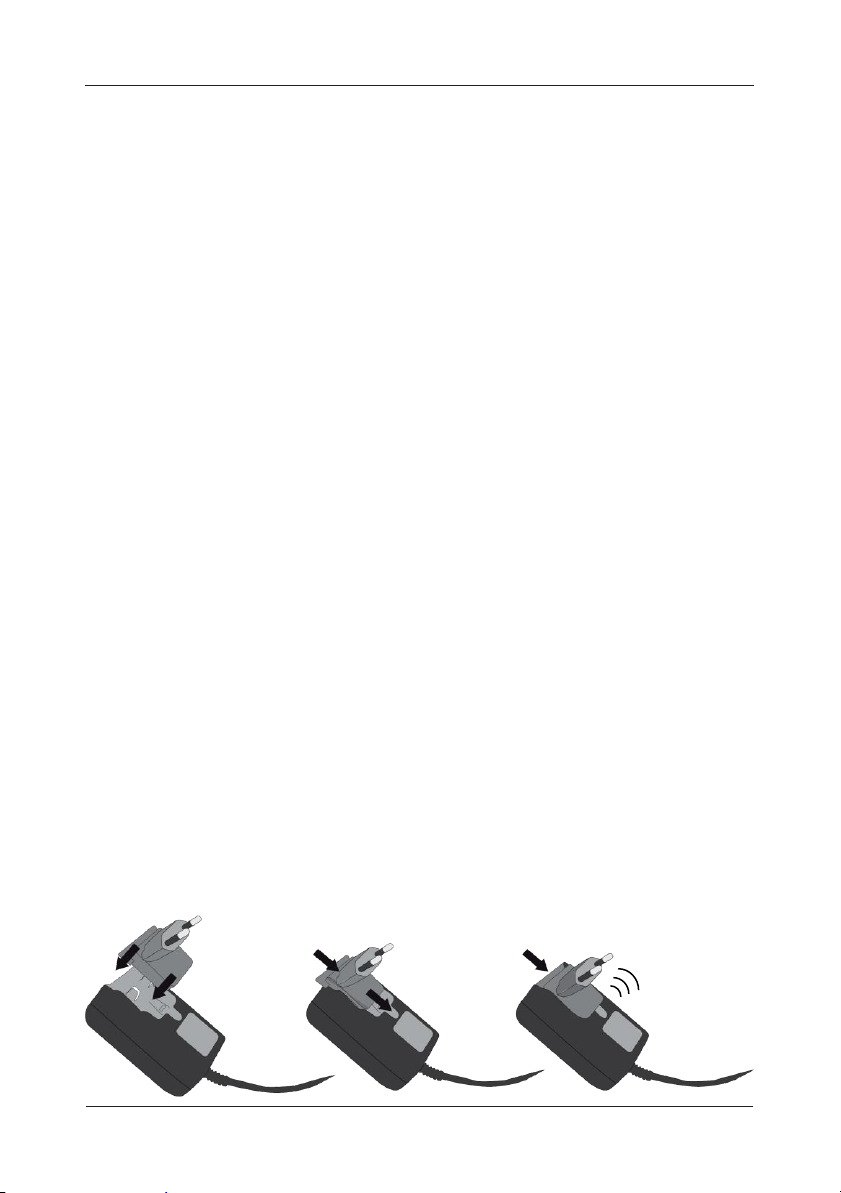
Insert the input plug included on the two power contacts, located on the
power supply, and push the plug until it clicks in to place.
Page 15

Wet Roof Pro’
15
Please ensure that the input plug ‘clicks’ into the power supply to ensure the
unit is safe to use. Connect the power supply to the charger. Finally, connect
the power supply to the mains (100-240V AC 50-60Hz).
To change the input plug, push the locking lug below the plug (e.g. using a
pen) until the plug can be moved slightly upwards. Then remove the plug.
Using the charger in a vehicle
Connect the DC charging cable to the charger. Connect the DC charging
cable to the 12V DC car socket of your vehicle (do not use in 24V DC truck
sockets). Please make sure that the power of the socket is switched on. Some
cars require the ignition to be switched on.
The charger is now ready for use. You can insert one 9V E-block and up to 4
AA/AAA/C/0 (in any combination) NiMH or NiCd rechargeable batteries. You
can also connect an USB cable using the USB charging socket to charge
other devices such as, smartphones or MP3 players. Insert all batteries with
correct polarity, corresponding to the symbols in the charging slot.
Charging of round cells
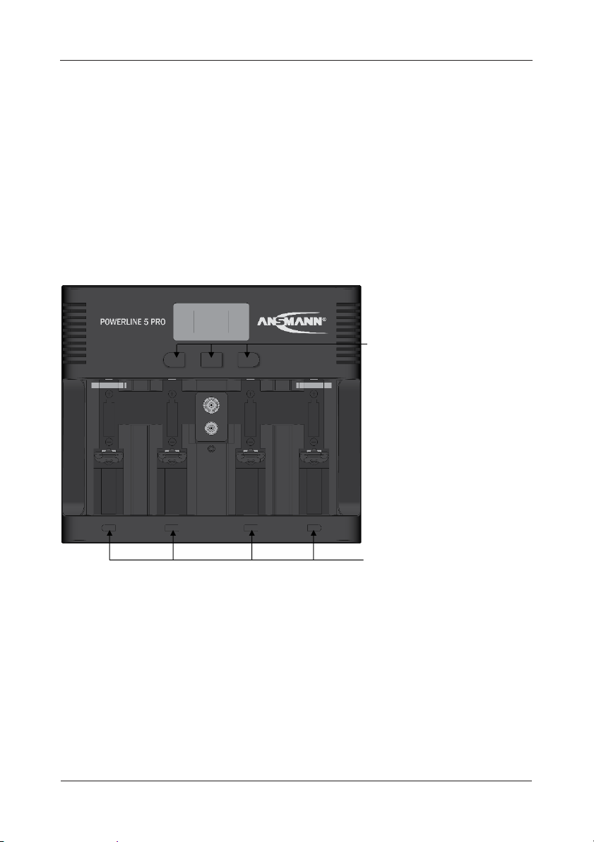
The charger has 3 function buttons; ‘CURRENT’, ‘DISPLAY’ and ‘MODE’ (see ‘A’
in illustration on page 16). Use these buttons to select the following settings:
• MODE button
Push the ‘MODE’ button within 8 seconds of inserting 1-4 rechargeable
batteries, to access one of the following charging programs:
A CHARGE: Charges battery. After charging is complete, charger will
automatically switch to trickle charging (trickle charge will commence
after all modes)
B DISCHARGE: Discharges battery before charging to minimize the
‘memory effect’ of batteries
C REFRESH: ‘DISCHARGE REFRESH’ or ‘CHARGE REFRESH’ status is shown on
the LCD display when charger cycles between discharging and
charging. This process will refresh old batteries and bring totem back to
the maximum capacity. Refresh will be repeated (max. 10x) until the
charger can no longer register a rise in capacity.
D TEST: Fully charges battery. LCD display shows ‘CHARGE TEST’ Discharges
battery and measures capacity. The LCD shows ‘DISCHARGE TEST’.
Recharges battery, ready for use. LCD shows ‘CHARGE TEST’.
Page 16
Instruction Manual
16
• CURRENT button
Push the ‘CURRENT’ button within 8 seconds of selecting a charging
program or after inserting batteries to select the charging current for the
program ‘CHARGE’ or ‘TEST’. Alternatively, choose the discharging current
for the program ‘DISCHARGE’ or ‘REFRESH’.
• DISPLAY button
Push the ‘DISPLAY’ button whilst charging or discharging to display the
charging/discharging current (mA), the voltage of the rechargeable
battery (V), the charging/discharging capacity (mAh or Ah) or the
remaining charging/discharging time (hh:mm).
Once the settings have
been selected, the
charger automatically
starts with the selected
parameters after 8
seconds. If no settings
are chosen, the LCD
display will flash after
inserting rechargeable
batteries. First the
voltage of the
rechargeable batteries
as well as the pre-set
charging program
‘CHARGE’ is shown.
Next, the pre-set
charging current of 600mA is shown. After 8 seconds the charging process
starts automatically using the pre-set parameters.
By using the 4 charging slot buttons (see ‘B’ in illustration above) you can
make individual settings for each rechargeable battery. To change a function
for a single rechargeable battery, press the corresponding button below the
charging slot for the chosen battery. The display will flash for this battery and
you can now change settings, as described above, for the single charging
slot using the function buttons ‘MODE’ and/or ‘CURRENT’.
A
B
Page 17
Wet Roof Pro’
17
If only one or two rechargeable batteries are inserted into the charger using
the two outer charging slots, in the mode ‘CHARGE’ and ‘TEST’ the charging
current can be increased up to 1500mA or 1800mA with the ‘CURRENT’
button. In this case the inner charging slots are disabled and cannot be used.
When charging three or four rechargeable batteries at the same time, the
charging current can be set to 400mA, 600mA or 800mA. Using the programs
‘DISCHARGE’ and ‘REFRESH’ discharging currents of 200mA, 300mA or 400mA
can be selected. The charging current is generally twice as high as the
chosen discharging current.
A few minutes before the rechargeable batteries are completely charged,
the charger reduces the charge current to ca. 200mA, regardless of the
previously selected charge current. This gentle full-charging extends the
service life of your rechargeable batteries.
After every charge/discharge procedure is complete, the charger adds a
short pause for the benefit of the rechargeable batteries before continuing
with the selected charging/discharging program.
ATTENTION: Please ensure that the rechargeable batteries are
designed for the respective charging current. For example, AAA
rechargeable batteries should not be charged with a 1500mA
or 1800mA charging current. We recommend choosing the
maximum charging current (mA) so that it does not exceed the
capacity value (mAh) of the inserted rechargeable battery.
it is normal that batteries may become warm during charging. After charging
is complete, the charger switches automatically to trickle charge. The trickle
charge prevents self-discharge of the batteries when left in the charger.
LCD Display
‘- --’ is shown when there is no rechargeable battery inserted but the
charger is connected to mains.
‘- -- mAh’ is shown during the first charging cycle when in ‘TEST’ mode.
‘Full’ is shown when the charging process is finished and the charger
switches to trickle charging, after finishing the charging program ‘TEST’ or
Page 18
Instruction Manual
18
‘REFRESH’, the display switches between ‘Full’ and the measured discharging
capacity in mAh/Ah.
‘ERR’ and ‘Lo’ are displayed alternately if the rechargeable battery inserted
has an internal short-circuit and so is defective.
‘ERR’ and ‘Hi’ are displayed alternately if the rechargeable battery inserted
exhibits a very high resistance or a non-rechargeable battery is inserted. In
such cases, no charging occurs. Please remove the defective batteries and
dispose of these in an environmentally friendly manner.
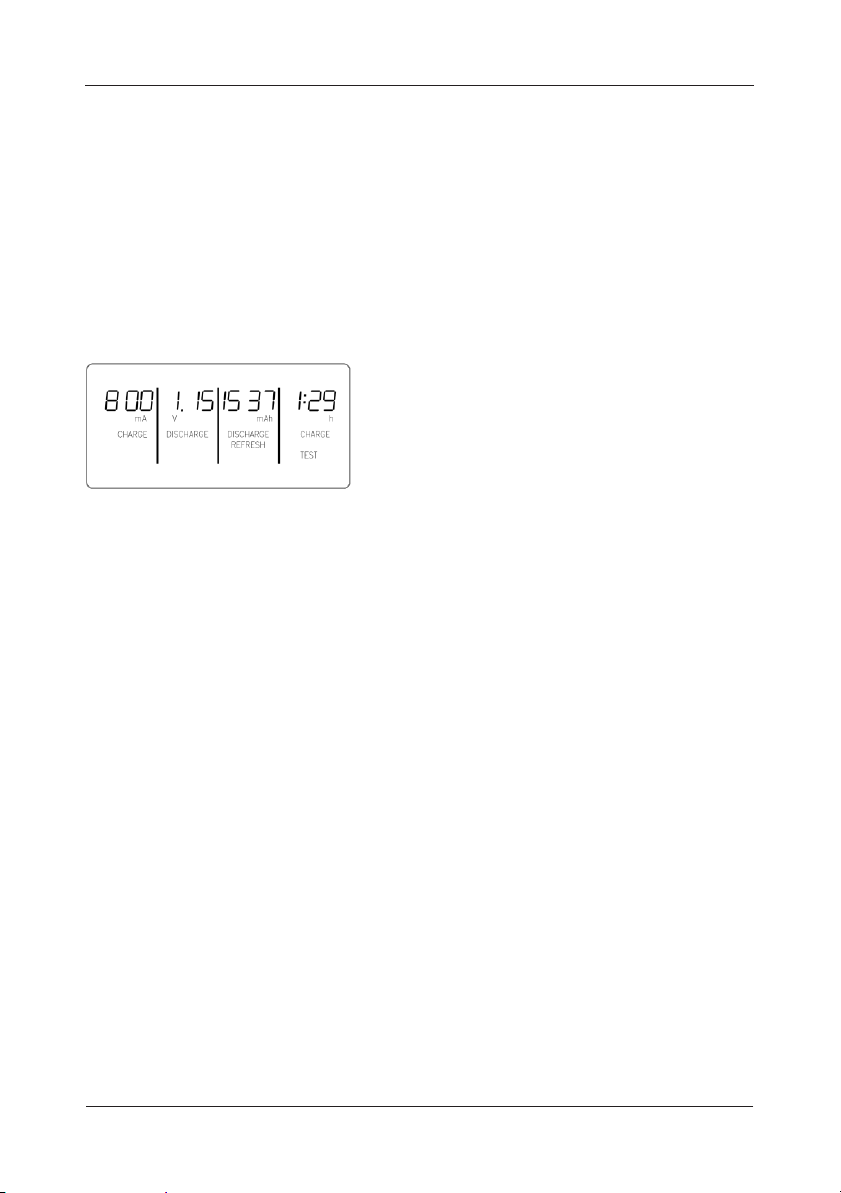
During the charging process, the pre-set
parameters are displayed as mentioned
under point 3 (DISPLAY). In addition, the
chosen charging program and the current
process (CHARGE or DISCHARGE) are shown.
In the illustration above you can see an example of the LCD display. This
example shows 4 different display modes and 4 different charging programs.
Charging 9V rechargeable batteries
One 9V battery can be charged, if no D-cells are inserted in the inner round
cell charging slots. When inserting the 9V battery, pay attention to the correct
polarity referring to the symbol in the charging slot. The LED charging indicator
illuminates red when the battery is inserted correctly. 9V batteries are
charged with a gentle current of c.15mA. After approx. 24 hours, the charge
process ends automatically and the LED illuminates green. The rechargeable
battery is charged and will be supplied with the trickle charge current so long
as it remains in the device. If the indicator flashes red, the battery has an
internal short circuit and should be disposed of.
Technical data
Input voltage external power supply: 100-240V AC / 50-60Hz
Input voltage car adapter: 12V DC (Do NOT use with 24V sockets)
Input voltage charger: 12V DC
Charging current for round cells: 400mA - 1800mA
Charging current for 9V batteries: 15mA
Maximum charging capacity: 11000mAh for round cells
300mAh for 9V block-style batteries
USB-charging socket: 5V/1000mA
Page 19
Wet Roof Pro’
19
Operation Principle
Wet roof leak detection relies on the roof’s surface moisture forming an
electrically conductive path to earth via the building substrate.
The Wet Roof Pro’ utilises the conductive properties of water to allow the
operator to locate the source or origin of a leak. This method is also known
as voltage gradient mapping or vector mapping.
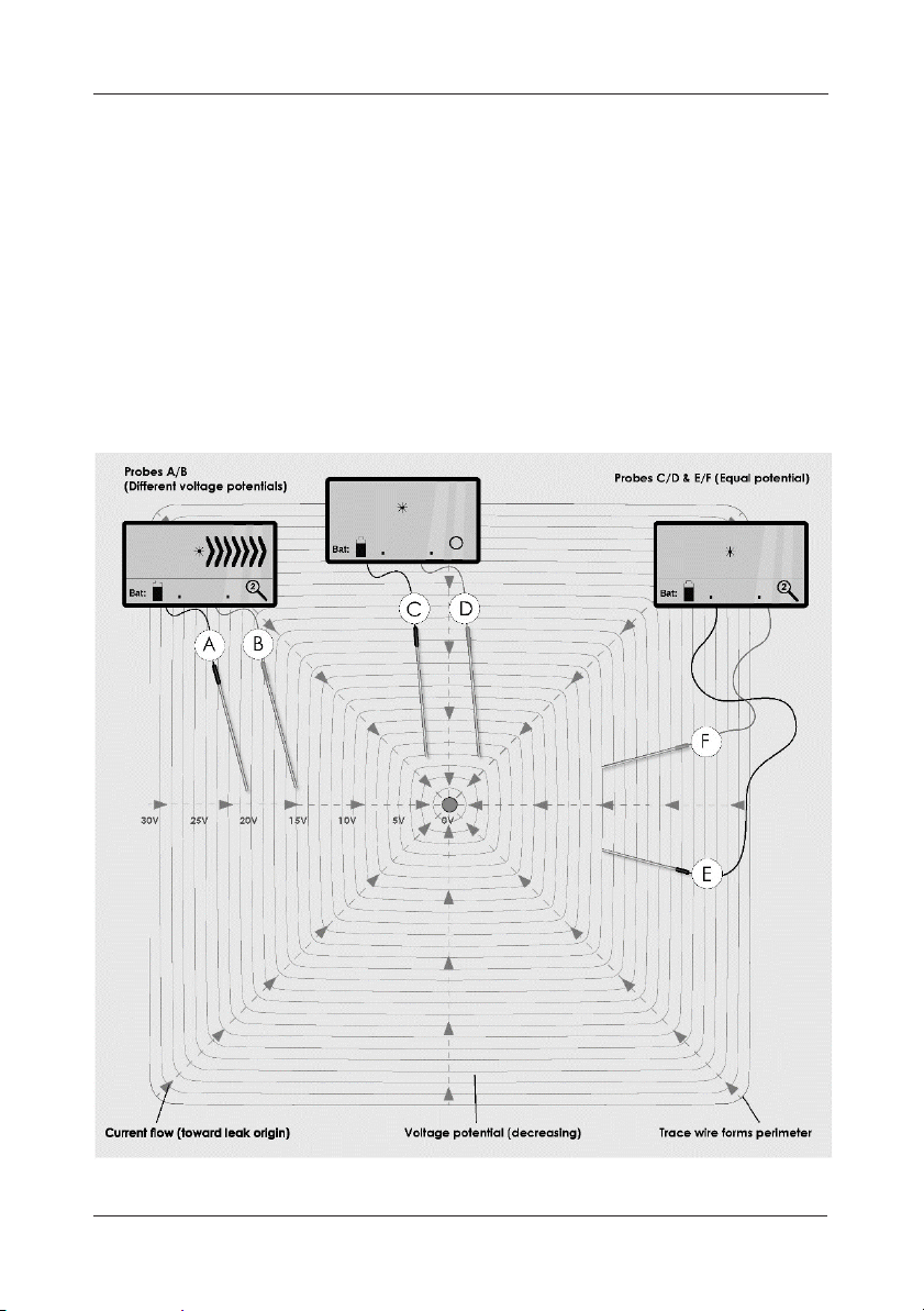
Fig. 11 shows a representation of how lines of equal voltage (similar to ripples
on a pond) may appear in a test area with a single fault and how the Wet
Roof Pro’ detector unit would display the measured potentials (voltage).
Fig.11 Principle of operation
Page 20

Instruction Manual
20
The stainless steel trace wire is used to form a conductive perimeter around
the area of roof to be tested and is connected to the negative output of
the Wet Roof Pro’ generator unit.
The positive output of the Wet Roof Pro’ generator is connected to a suitable
earthed point of the building substrate. When the generator unit pulses a
voltage is applied to the trace wire, electrical current flows from the trace
wire toward the origin of the leak (denoted by the blue lines).
As current flows the measured voltage potential (Dark blue/black concentric
rings) decreases as the voltage approaches the leak origin.
It therefore follows that the further the survey probe are set apart,
the greater
the number of directional chevrons that will be displayed. This is due to there
being a larger voltage difference between the two poles.
In fig.11 the difference between measured voltage potentials at probes A &
B is approximately 6.0 volts, the detector unit will therefore display direction
chevrons to the right (due to current flowing from left to right i.e. trace wire
to leak origin).
Probes at points C & D will show no direction because both probes are on
lines of equal voltage potential (20.0 volts) as are probes at points E & F.
As the detector unit displays the directional chevrons, it is the direction of
the chevrons not their magnitude that the operator is guided by.
The voltage potential or gradient within a test area can be somewhat
unpredictable due to several variables, these include salinity of the water
and the electrical resistance of the fault to building earth point. The greater
the moisture penetration between roof membrane and building structure
the greater the current flow will be.
Page 21
Wet Roof Pro’
21
Using the Wet Roof Pro’
Preparation
Before conducting a survey, the roof must be wet and the trace wire needs
to have been laid down to form a perimeter bordering the area to be tested.
Use the 10m lead (clip to black plug) to connect the ends of the trace wire to
form a closed loop.
It is also important to ensure that there is good contact between the trace
wire and roof surface to ensure an efficient survey can be conducted.
If necessary the trace wire may be weighted down or fixed in position with
adhesive tape if possible.
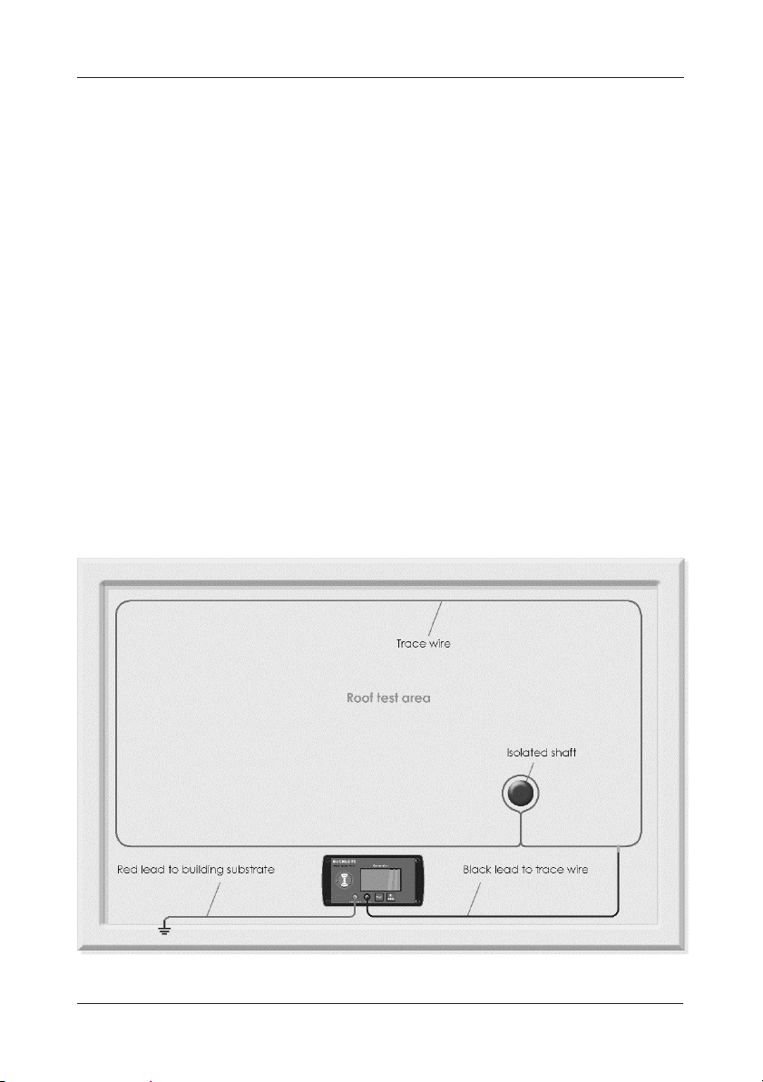
Structures protruding through the roof such as ventilation shafts and drain
pipes must be screened off by either looping around them with the trace
wire or an additional loop of wire which must be connected to the main
trace wire. Defects and faults located in a membrane during test can also be
isolated in this way in order to continue testing for further leaks (see fig.12).
’
Generator
Subs tra te Tr a ce
Pulse
O/I
Sele ct
Fig12. Wet Roof Pro’ Generator connections
Page 22
Instruction Manual
22
Prior to using the Wet Roof Pro’ for the first time the batteries will need to be
installed, once inserted the batteries can remain in the units until charging is
required.
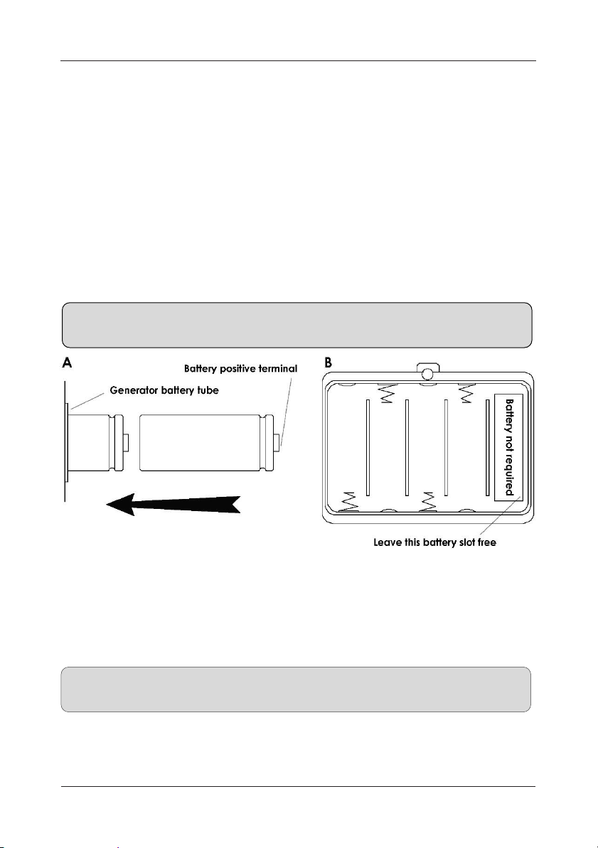
To fit the generator unit batteries (4 x ‘D’ cell) remove the twist-grip cap from
each battery tube located on the rear of the unit and slide two batteries into
each battery tube (positive to cap) as shown in fig. 13a and refit the caps.
To fit the detector batteries, firstly remove the detector unit from its protective
neck pouch and open the battery compartment cover located on the rear of
the case. Next, observing the correct polarity, insert an ‘AA’ cell into each of
the four battery slots.
NOTE: Although the battery compartment has five positions only four
batteries are fitted to the detector unit (see figure 13b).
Fig13. Fit batteries A - Detector Unit, B - Generator Unit
Connect the 10m lead (black plug) from the trace wire to the negative
output socket of the Wet Roof Pro’ generator unit with the positive output of
the generator connected to a good building earth (substrate) point this time
using the 10m red 4mm plug to crocodile-clip lead.
Attention! Avoid submersing the generator units output sockets in standing
water as this could cause a short-circuit across the output sockets.
The generator unit should ideally be raised above any standing water on the
roof surface. If it is not possible to site the generator in a dry place then the
trace wire reel can act as a stand to raise the unit away from the water.
Page 23

Wet Roof Pro’
23
The left and right hand survey poles comprise of three sections, an upper
handle, a middle section and the lower probe-tip section. To assemble the
survey poles, simply screw the sections together.
Connect each survey pole to the detector unit using the respective 1m red
and black test leads (stored in a small pocket on the rear of the detector’s
protective neck pouch).
Surveying
When all preparations as detailed on page 20 have been completed, switch
both generator and detector units on. Select the required generator pulse
frequency, duration and alarm.
Once inside the test area, position the poles at a comfortable distance
apart on the roof surface and begin the survey at one corner of the trace
wire perimeter.
Interference may cause a slight offset to be noticed on the detector, but
not in a pulsed manner. The direction of the observed pulse indicates the
direction of the leak. Note that it is the direction and not strength of the
pulse that is important.
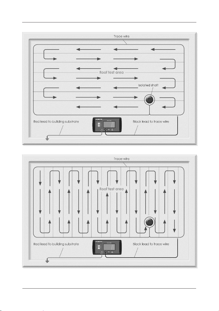
One possible method for conducting a survey is to follow a course similar to
that of mowing a lawn, continuing along the roof to the opposite corner of
the trace wire then turn through 180° and return. As you turn, the direction
response will switch sides.
Alternatively, continue in the direction of the pulse until the detector reading
swings in the opposite direction, indicating that you have passed the leak
origin. Now turn through 90˚, measure in a direction perpendicular to this
line, see fig.14 for detail (also refer to fig.11).
During testing if a momentary weak pulse is detected which always leads
to the centre of the test area, this indicates that no leaks are present. This
may be verified by shifting the position of the trace wire, which will shift the
apparent origin of the weak pulse respectively.
Page 24
Instruction Manual
24
Fig.14 Roof survey
Page 25

Wet Roof Pro’
25
Maintenance
We strongly recommend the Wet Roof Pro is serviced annually by
Buckleys (UVRAL) Ltd. or one of our approved service & repair agents in
order to ensure it works at optimum performance, accuracy and safety.
By registering your Wet Roof Pro’s warranty at the time of first purchase, we
will send annual reminders for scheduled maintenance as well as extending
the warranty. For more information, see the flyer enclosed with this manual.
Remove batteries from both units if they are not going to be used for a
prolonged period of time.
Regularly inspect all items and accessories within the Wet Roof Pro’
kit, checking for damage. Check the integrity of the survey poles (fully
assembled) and all leads, replacing any that are damaged or broken.
The exterior of both units should be cleaned regularly using a moistened
cloth. A mild detergent mixture can be used for more stubborn stains (99%
water +1% mild detergent).
Do not use abrasive cleaners as this could damage the display lens. Under
no circumstances should cleaning fluids be allowed to enter the input/
output sockets of the units.
Disposal information
Producer registration number: WEE/HJ0051TQ
This product must be disposed of in accordance with UK WEEE
regulations.
For further information on UK WEEE regulations click on:
www.gov.uk/government/publications/weee-regulations-2013-governmentguidance-notes
Page 26

Instruction Manual
26
EC Declaration of conformity
We:
Buckleys (UVRAL) Ltd
As manufacturer of the apparatus listed,
declare that the
product:
Wet Roof
Pro’
Is manufactured in conformity
with
the following directives:
2104/30/EU
2014/55/EU
Authorised by:
J P Hoveman
CEO, Buckleys (UVRAL)
Ltd.
Page 27

Wet Roof Pro’
27
Contact details
Manufacturer: Buckleys (UVRAL) Ltd
Address: Buckleys
House
Unit G, Concept Court
Shearway Business Park
Shearway Road
Folkestone
Kent CT19 4RG, UK
Tel: +44 (0)1303 278888
Fax: +44 (0)1303 274331
Website: www.buckleysinternational.com
Distributor details
Page 28

Product registration
Thank you for choosing a Buckleys product,
we are sure it will provide you with many years
of reliable service.
Please register this product via Buckleys’
website and download the
Warranty Registration Certificate.
Register your product in 5 minutes
Once your product is registered, you will receive
the following benefits:
•
FREE
annual service & calibration reminders by email
•
Latest
industry news relating to your product
• Be the
first
to hear about our new products
We strive to improve the quality of our products and service.
Registering your product helps us monitor overall quality of our products,
service and dealer network. Additionally, if we ever need to contact you
regarding your product, we are able to do so immediately.
We will also send you annual service/calibration reminders by email to help
ensure your product is always in perfect working order.
To register your product, simply visit:
www.buckleysinternational.com/registration
...Complete the online form and click on SUBMIT.
5830-0033/WRP/IM/ENG/V.1-19
 Loading...