

Page 1
MANUFACTURERS OF SPECIALIST TEST EQUIPMENT
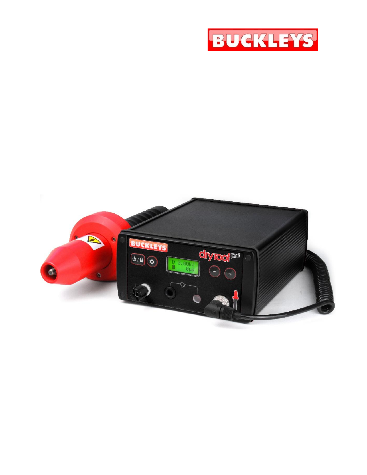
Dry Roof Pro’
Operating Instructions
English Version
Please read carefully before use
Page 2

Page 3

Dry Roof Pro’’
3
Contents
Description
Page
4
Specifications
5
Unpacking
6
Operating instructions
7
Calculating the test voltage
8
Settings
8
Testing
8
Safety precautions
10
Types of fault
11
Maintenance
12
Battery charger
13
Electromagnetic Compatibility
19
Declaration of Conformity
22
Contact Details
23
Page 4

Instruction Manual
Description
The Dry Roof Pro’ is designed to deliver an adjustable, stabilised DC output
voltage for the detection of leaks, defects and porosity in non-conductive flat
roof coverings. The Dry Roof Pro’ features a 2x8 character backlit LCD which
displays the user options for setting the test voltage, alarm volume, alarm
threshold sensitivity, the test voltage formula and an optional audible warning
tick that sounds when the high voltage is enabled. The test voltage may also
be automatically calculated from the entered coating thickness. Fault
detection is indicated by an audible alarm and illumination of a red LED on
the front panel. A low-tension coiled lead connects the unit to the test probe.
The user options are selected by a membrane keypad input. The selected
values and options are retained when the unit is switched off. During
operation, the test voltage will remain regulated as the batteries discharge.
Since the output voltage is DC, the material under test is subjected to
minimum electrical stress.
4
Page 5

Dry Roof Pro’
5
Specifications
Maximum output current: Less than 1mA (continuous)
DC sensitivity: Adjustable - 10µA to 450µA (pre-set to 350µA)
Batteries: 4 x D-cell Batteries
Meter accuracy: Volts: +/-1.0% +/-1 digit
Current: +/- 2.0%
Current meter FSD: 450µA
Test voltage formula: NACE SP-02-74
Unit dimensions: 172mm(W) x 85mm(H) x 235mm(D)
Unit weight: 2.9kg – Incl. carry case, batteries,
interconnecting lead and ESD wristband
Handle weight: 720g
Maximum relative humidity: 80% non-condensing
Altitude: Up to 2000m
Temperature range: 0ºC - +40ºC
Output voltage range:
Low range: 2-10kV in 10V steps
High range: 10.1-40kV in 100V steps
Polarity: Positive
Operating times (typical): 8 hours* (at 40kV)
* Test criteria BS EN-50356. Test unit fitted with 10000mAh NiMH cells.
Page 6
Instruction Manual
6
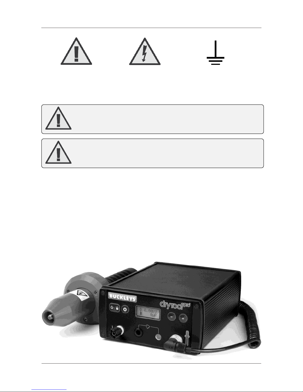
Caution, risk of danger Caution, risk of shock Earth return (grounding terminal)
Misuse or failure to comply with the guidelines outlined in this manual may
impair the safety provided by the equipment.
Unpacking
Remove the unit and accessories from the packaging and check for any
damage. Should any item be damaged or missing, notify the supplier and
carrier immediately, keep all packing material for inspection and do not
use the equipment.
Please refer to the specific Buckleys data sheet for details of kit contents.
Keep all packaging in case the unit needs to be returned for repair or
calibration.
IMPORTANT: This product must not be used in combustible atmospheres
or ATEX Hazardous Areas, such as fuel stations or in proximity to any
combustible gas (including oxygen).
IMPORTANT: This product can cause radio interference and caution must
be taken when operating in sensitive environments such as hospital roofs.
Ensure the product is correctly connected to an appropriate earth.
Page 7
Dry Roof Pro’
7
Operating instructions
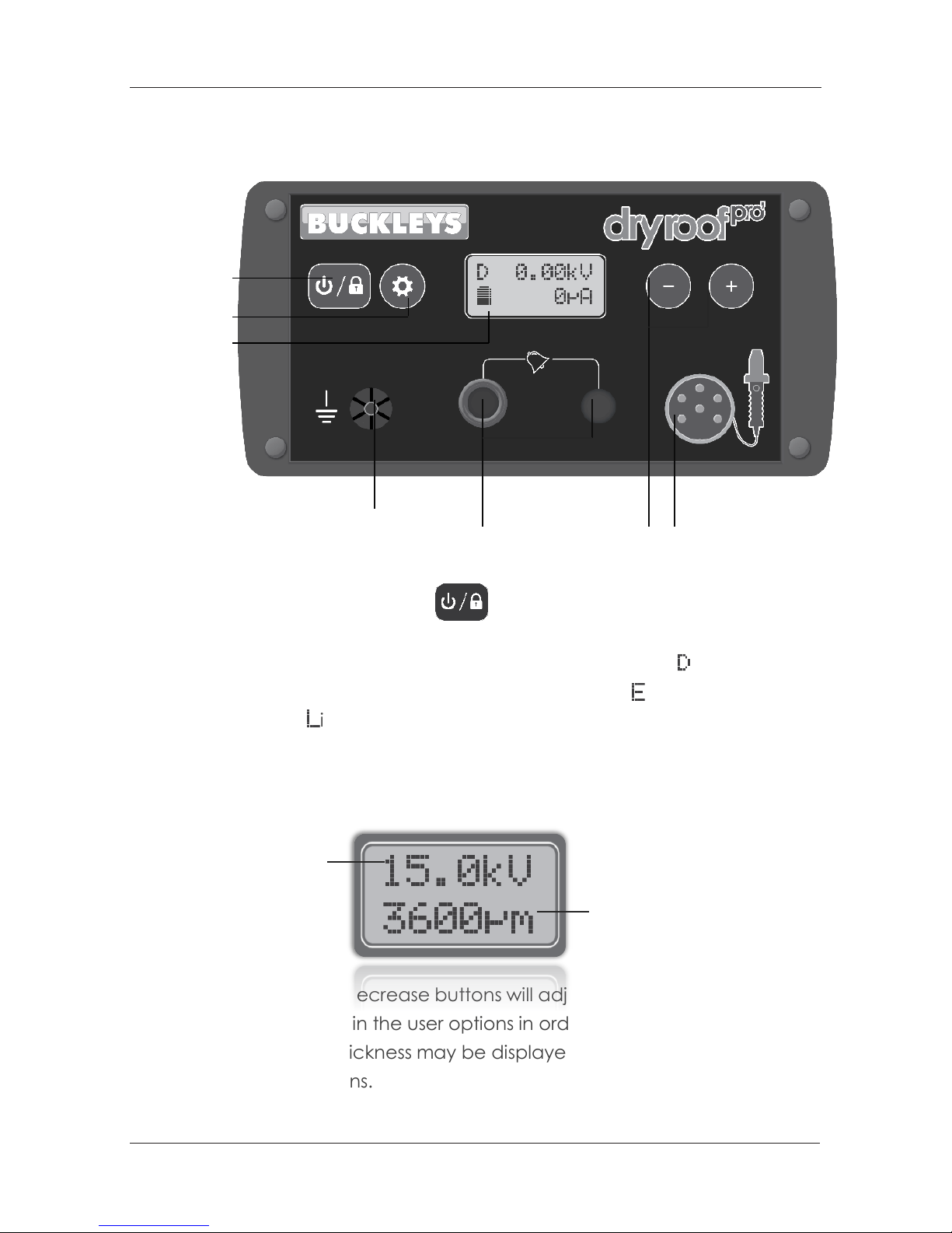
Switch the unit on by pressing the button. The LCD will momentarily
show the unit type then the set voltage before displaying the battery
condition, the preset voltage and the current conditions. The (HV status) in
the top left of the LCD indicates that the HV is disabled, indicates that the
HV is enabled and indicates the HV is enabled and locked on. The battery
level indicator is characterised to NiMH rechargeable cells.
The test voltage can be selected by dielectric strength or coating thickness.
Test voltage
Coating thickness in microns
Pressing the increase or decrease buttons will adjust the values. The formula
option must be selected in the user options in order to display the coating
thickness. The coating thickness may be displayed in metric or imperial
format via the user options.
Increase/decrease
buttons
Test probe
connection
Alarm sounder
& light
Earth connection socket
Settings button
LCD display
ON/OFF/LOCK
button
Page 8
Instruction Manual
8
coating
\
T
=
(
)
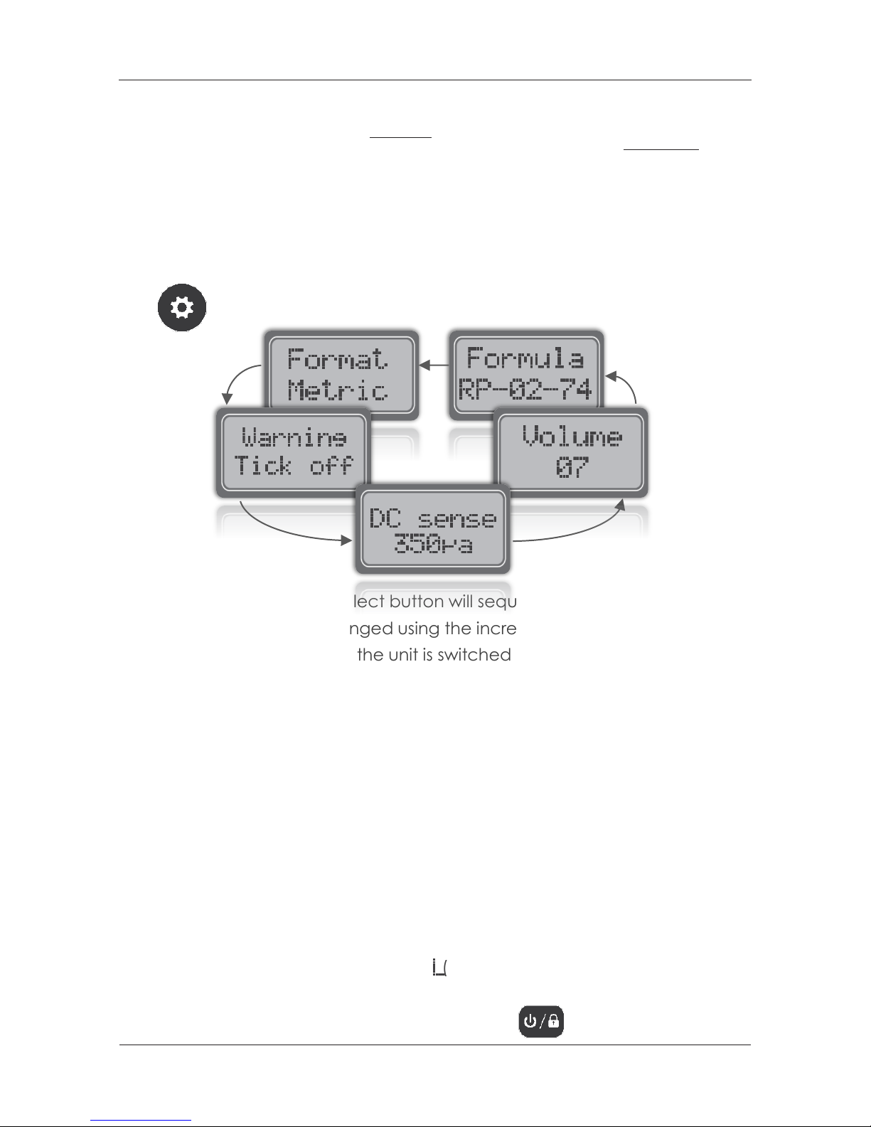
Calculating the test voltage
Test Voltage = 1250 √ T
coating
Test voltage
250
Metric calculation example according to NACE RP-02-74
Settings
The button steps through the user options:
Pressing and releasing the select button will sequentially step through the user
options. Values may be changed using the increase/decrease buttons. The
values will be retained when the unit is switched off.
Testing
Attach the necessary accessories to the test probe. Connect the coiled
connection cable between the socket located on the lower right-hand side
of the front panel and the test probe. Connect the earth lead between the
unit’s earth socket and the substrate of the test subject. Ensure the substrate
of the test subject is at earth/ground potential.
Pressing the test probe ON button will energise the test electrode to the
selected test voltage that will be displayed in the LCD along with the HV status
and the amount of DC current flowing from the test electrode. During testing
the HV may be locked on by pressing and releasing the I/O / (lock) button. The
unit will sound two bleeps and display (HV status) indicating the HV is now
locked on and will continue to generate HV when the test probe ON button is
released. To unlock and disable the HV press the button once more.
Where T is coating thickness in
thou/mils (0.001”)
Where T is coating thickness in
microns (0.001mm)
Page 9
Dry Roof Pro’
9
Fault detection is indicated by an audible alarm and illumination of a
red LED on the front panel. The DC (alarm) sensitivity of the unit should be
adjusted to suit the material under test. The value shown in the
option refers to the DC current in micro-amps allowed to flow from the
test electrode before an alarm is indicated, there are many variables that
may contribute in changes to the amount of current flowing including the
electrode size and its velocity.
The DC sensitivity may be adjusted from 10µA, the most sensitive setting, to
450µA, the least sensitive setting, in addition the PHD Pro’30 and PHD Pro’40
units may be set to a ‘Spark Only’ setting where the output voltage and DC
current monitoring are disabled. In this setting the alarm responds only to a
total air discharge of the test probe. The default sensitivity is set at 350µA.
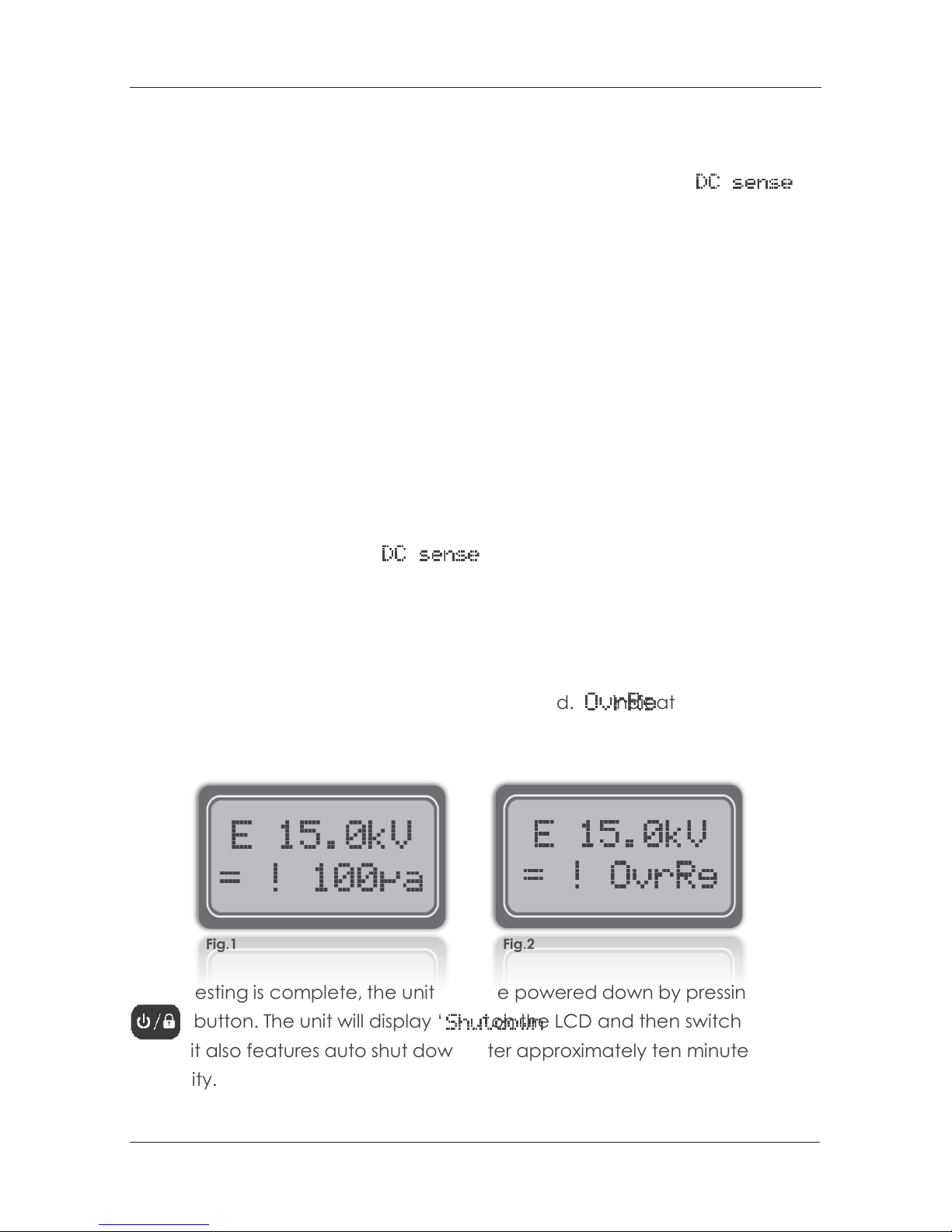
Alarms may be generated by the follow conditions:
●
If the DC current flowing from the electrode is equal to or greater than
that set by the user in the
option. (Fig 1)
●
A spark caused by the ionisation of the air that exists in an imperfection of
the coating material. (Fig 2)
●
If the unit is excessively loaded thus reducing the test voltage.
In this case the generator will continue to apply a current to the fault
and the reduced test voltage will be displayed.
indicates that the
electrode current has exceeded 450µA. If the ‘Spark only’ option is set, the
unit ignores any reduction in test voltage.
Fig.1 Fig.2
When testing is complete, the unit may be powered down by pressing the
button. The unit will display ‘
’ on the LCD and then switch off.
The unit also features auto shut down after approximately ten minutes of
inactivity.
Page 10
Instruction Manual
10
Safety precautions
All high voltage testing equipment should be operated by responsible
authorised personnel only.
The output voltage of this equipment is derived from a high impedance
source and is current limited. However, when the equipment is in use, should
the operator accidentally contact the test electrode they will receive an
electric shock. If this situation is unavoidable we recommend that rubber or
plastic insulating gloves be worn. Furthermore, the operator should be in
good health and - in particular - not suffer from any cardiac condition.
During testing, a static charge may accumulate on the surface under
test. If the operator is walking on the surface, he or she may also become
‘charged-up’. When discharged to earth, this charge could result in a static
electric shock, such as may be experienced in the home under certain
weather conditions. Whilst such a shock does not normally present any
danger to the user, it can be unpleasant. In most cases, the operator can
avoid this by wearing the blue ESD wristband supplied and ensuring it is
connected by the blue cable to the grounding terminal (4mm socket) on
the Dry Roof Pro’s test probe handle, or the earthing point on the instrument
case. In all cases it is essential to ensure that the instrument is correctly
earthed.
DANGER: Do not use test equipment of this type in any
combustible atmosphere as the test voltage may cause a
spark from which an explosion could result. Therefore, the plant
or site Safety Officer should be consulted before proceeding
with any testing.
We cannot stress too strongly that equipment of this type
should be operated only with a secure connection to earth
or ground. This applies especially to the testing of plant or
test pieces, which do not have a permanent connection to
ground. Failure to comply with this procedure may cause
shock to the operator or damage to the equipment.
Page 11
Dry Roof Pro’
11
Types of fault
Crack Blowhole
Burr
Air bubble Inclusion
Coating
Substrate
Fig 3. Coating faults
Crack: May be encountered with hard coating materials that are applied
hot then shrink as they cool or a coating that has been damaged. Cracks
can be at an angle and the distance between the electrode and the
substrate will be greater, needing a higher voltage to jump the gap.
Blowhole: Formed as the coating cools, normally over welds or trapped
air coming from a ‘two-part’ coating as it cures. The blowhole may not go
through to the substrate and will only be detected if the test voltage is high
enough to break down the remaining coating material.
Burr: Burrs on welds, or holes in the substrate reduce the coating thickness
to a point where the test voltage exceeds the dielectric strength of the
coating and it breaks down.
Air bubble: Trapped air will only be detected when the test voltage is
high enough to break down the remaining coating. i.e. to find air bubbles
greater than half the coating thickness the test voltage would need to be at
least half the dielectric strength of the total coating thickness.
Inclusion: Dirt, dust, even flies that get trapped as coatings are applied. If
the inclusion is non-conductive and the coating bonds to it, it may not be
detected; again, the test voltage will need to break down any coating
covering the inclusion.
Page 12
Instruction Manual
12
Maintenance
The Dry Roof Pro’ is designed for minimum maintenance by the user, however
the following periodic checks/actions are recommended. Send the entire kit
and electrode back to the manufacturer or distributor for recalibration
annually. Remove the batteries for transportation, or if the unit is not in
use for
prolonged periods.
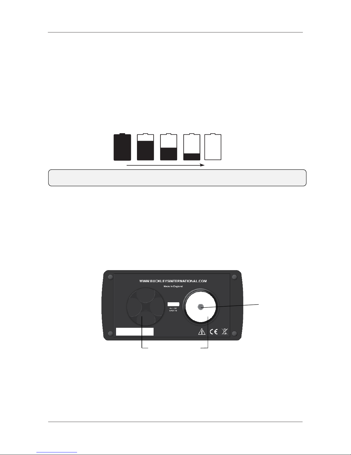
Battery status indicator
100% 0%
Note: The battery level indicator is characterised to NiMH rechargeable cells.
The battery compartments are located on the unit’s rear panel and are easily
accessible. When refitting, the batteries ensure their positive identification pips
face the rear of the unit. Use only good quality high capacity batteries of at
least 10000mAh (rechargeable NiMH) or 15000mAh (non-rechargeable)
ratings.
Rechargeable batteries reach optimum performance after several chargedischarge cycles.
Positive ID pips
Battery compartments
The exterior of the unit should be cleaned regularly. Dirt that is difficult to
remove from the unit and handle may be removed with a moistened cloth
(99% water +1% mild detergent). Mild solutions may be used to remove
greasy dirt. Under no circumstances may the cleaning fluid be allowed to
enter the unit. The use of other cleaning agents may lead to damage to the
unit’s surface areas.
Page 13

Dry Roof Pro’
13
Battery charger
Safety
• Please read these operating instructions carefully before using the charger.
• Do not use the device if there are any signs of damage to the housing, plug or
cable. If you do find any damage to the unit, please contact an authorised
dealer.
• Use only with NiMH/NiCd cells. Other battery types may explode;
• Please make sure batteries have been inserted with the correct polarity (+/-)
prior to use.
• Please note that due to the high charging current, only high-quality brand
rechargeable batteries should be charged with this device. Low quality cells
may leak and damage the charger and invalidate the warranty.
• Keep the charger in a dry place away from direct sunlight;
• To avoid the risk of fire and/or electric shock, the charger must be protected
against high humidity and water.
• To clean the unit, disconnect the power supply and only use a dry cloth.
• Never attempt to open the charger.
• Keep out of the reach of children. Children should be supervised to ensure
that they do not play with the charger.
• The device is not to be used by children or people with reduced physical,
sensory or mental capabilities. In addition, novice users who have not fully
read these instructions should be supervised or given instruction before use.
• If the safety instructions are not followed, it may lead to damage to the device
or battery and could cause injury to the user.
• We recommend the use of ANSMANN rechargeable batteries with this
product.
Technical overview
• Charger for 1 to 4 x AAA, AA, C or D and 1 x 9V E-block; includes USB
charging output (5V/1000mA) which can be used at the same time as
charging batteries.
• Suitable for NiCd, NiMH batteries
• Reverse polarity protection
• Trickle charging
• For worldwide use (100V-240V AC / 50-60Hz) and car use (12V DC only. Not
24V used in trucks)
Page 14
Instruction Manual
14
CLICK
For charging round cells:
• Multifunction clear LCD display with backlight
• Adjustable charging current for each charging slot 400mA, 600mA, 800mA
for 1-4 rechargeable batteries 400mA, 600mA, 800mA, 1500mA, 1800mA for
1-2 rechargeable batteries
• Individual charging programs for each charging slot:
- CHARGE
- DISCHARGE (discharges battery before charging to minimize the
‘memory effect’ of batteries)
- REFRESH (cycle of charging and discharging to refresh old batteries)
- TEST (fully charges battery - discharge battery and measures capacity,
recharges battery)
• Capacity measurement in mAh/Ah
• The selected charging program can be easily read on the LCD display
• Microprocessor controlled charging and supervision of each battery
• Individual monitoring of the current parameters:
- VOLTAGE (V)
- CAPACITY (mAh/Ah)
- TIME (hh:mm)
- CURRENT (mA)
• Multiple over charging protection per bay and auto cut-off function
• Faulty cell detection/accidental alkaline battery insertion detection
For 9V rechargeable batteries:
• LED charging indication
• Charging current 15mA
• Automatic termination of the charging process by 24-hour timer
Operation
Using the charger in a mains power outlet
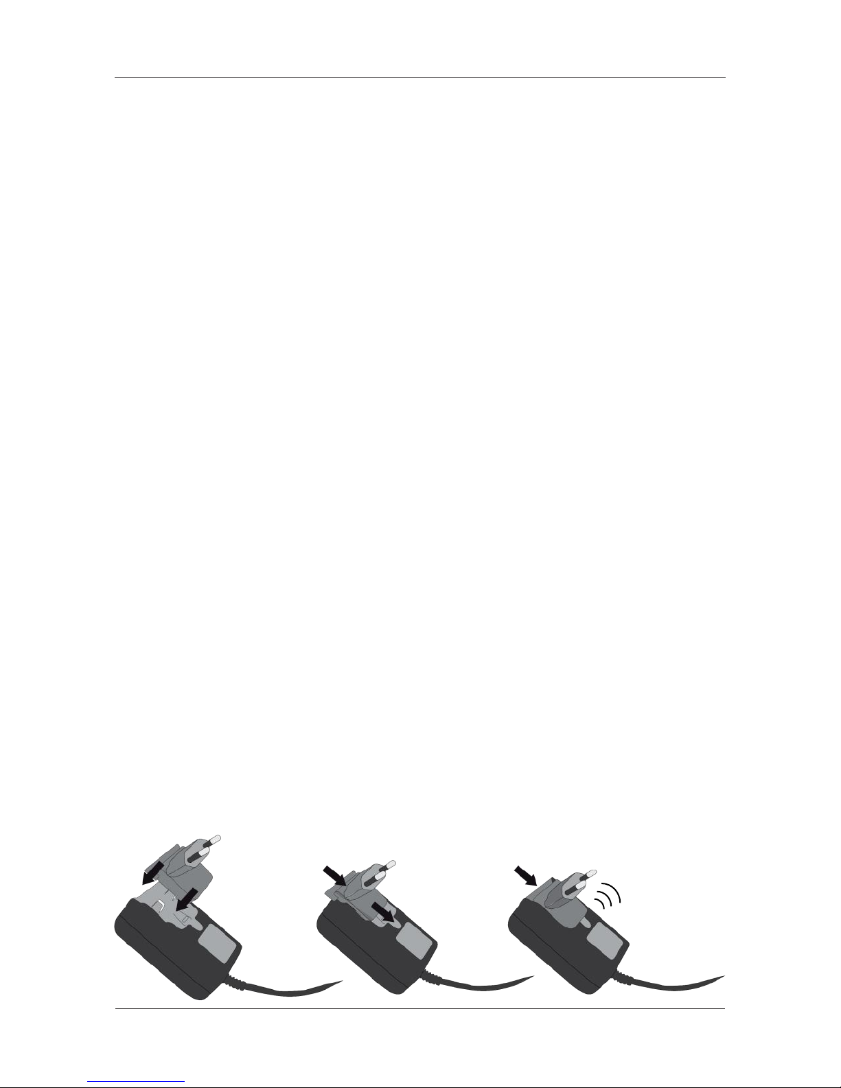
Insert the input plug included on the two power contacts, located on the power
supply, and push the plug until it clicks in to place.
Page 15

Dry Roof Pro’
15
Please ensure that the input plug ‘clicks’ into the power supply to ensure the
unit is safe to use. Connect the power supply to the charger. Finally, connect
the power supply to the mains (100-240V AC 50-60Hz).
To change the input plug, push the locking lug below the plug (e.g. using a
pen) until the plug can be moved slightly upwards. Then remove the plug.
Using the charger in a vehicle
Connect the DC charging cable to the charger. Connect the DC charging
cable to the 12V DC car socket of your vehicle (do not use in 24V DC truck
sockets). Please make sure that the power of the socket is switched on. Some
cars require the ignition to be switched on.
The charger is now ready for use. You can insert one 9V E-block and up to 4
AA/AAA/C/0 (in any combination) NiMH or NiCd rechargeable batteries. You
can also connect an USB cable using the USB charging socket to charge
other devices such as, smartphones or MP3 players. Insert all batteries with
correct polarity, corresponding to the symbols in the charging slot.
Charging of round cells
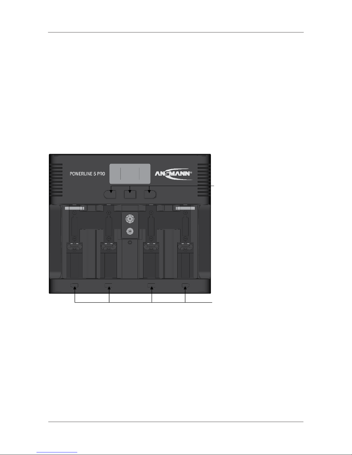
The charger has 3 function buttons; ‘CURRENT’, ‘DISPLAY’ and ‘MODE’ (see ‘A’
in illustration on page 16). Use these buttons to select the following settings:
• MODE button
Push the ‘MODE’ button within 8 seconds of inserting 1-4 rechargeable
batteries, to access one of the following charging programs:
A CHARGE: Charges battery. After charging is complete, charger will
automatically switch to trickle charging (trickle charge will commence
after all modes)
B DISCHARGE: Discharges battery before charging to minimize the
‘memory effect’ of batteries
C REFRESH: ‘DISCHARGE REFRESH’ or ‘CHARGE REFRESH’ status is shown on
the LCD display when charger cycles between discharging and
charging. This process will refresh old batteries and bring them back to
the maximum capacity. Refresh will be repeated (max. 10x) until the
charger can no longer register a rise in capacity.
D TEST: Fully charges battery. LCD display shows ‘CHARGE TEST’ Discharges
battery and measures capacity. The LCD shows ‘DISCHARGE TEST’.
Recharges battery, ready for use. LCD shows ‘CHARGE TEST’.
Page 16
Instruction Manual
16
• CURRENT button
Push the ‘CURRENT’ button within 8 seconds of selecting a charging
program or after inserting batteries to select the charging current for the
program ‘CHARGE’ or ‘TEST’. Alternatively, choose the discharging current
for the program ‘DISCHARGE’ or ‘REFRESH’.
• DISPLAY button
Push the ‘DISPLAY’ button whilst charging or discharging to display the
charging/discharging current (mA), the voltage of the rechargeable
battery (V), the charging/discharging capacity (mAh or Ah) or the
remaining charging/discharging time (hh:mm).
Once the settings have
been selected, the
charger automatically
starts with the selected
parameters after 8
seconds. If no settings
are chosen, the LCD
display will flash after
inserting rechargeable
batteries. First the
voltage of the
rechargeable batteries
as well as the pre-set
charging program
‘CHARGE’ is shown.
Next, the pre-set
charging current of 600mA is shown. After 8 seconds the charging process
starts automatically using the pre-set parameters.
By using the 4 charging slot buttons (see ‘B’ in illustration above) you can make
individual settings for each rechargeable battery. To change a function for a
single rechargeable battery, press the corresponding button below the
charging slot for the chosen battery. The display will flash for this battery and
you can now change settings, as described above, for the single charging slot
using the function buttons ‘MODE’ and/or ‘CURRENT’.
A
B
Page 17
Dry Roof Pro’
17
If only one or two rechargeable batteries are inserted into the charger using the
two outer charging slots, in the mode ‘CHARGE’ and ‘TEST’ the charging current
can be increased up to 1500mA or 1800mA with the ‘CURRENT’ button. In this
case the inner charging slots are disabled and cannot be used. When charging
three or four rechargeable batteries at the same time, the charging current can
be set to 400mA, 600mA or 800mA. Using the programs ‘DISCHARGE’ and
‘REFRESH’ discharging currents of 200mA, 300mA or 400mA can be selected.
The charging current is generally twice as high as the chosen discharging
current.
A few minutes before the rechargeable batteries are completely charged, the
charger reduces the charge current to c.200mA, regardless of the previously
selected charge current. This gentle full-charging extends the service life of your
rechargeable batteries.
After every charge/discharge procedure is complete, the charger adds a short
pause for the benefit of the rechargeable batteries before continuing with the
selected charging/discharging program.
ATTENTION: Please ensure that the rechargeable batteries are
designed for the respective charging current. For example, AAA
rechargeable batteries should not be charged with a 1500mA
or 1800mA charging current. We recommend choosing the
maximum charging current (mA) so that it does not exceed the
capacity value (mAh) of the inserted rechargeable battery.
It is normal that batteries may become warm during charging. After charging is
complete, the charger switches automatically to trickle charge. The trickle
charge prevents self-discharge of the batteries when left in the charger.
LCD Display
‘- --’ is shown when there is no rechargeable battery inserted but the charger is
connected to mains.
‘- -- mAh’ is shown during the first charging cycle when in ‘TEST’ mode.
‘Full’ is shown when the charging process is finished and the charger switches
to trickle charging, after finishing the charging program ‘TEST’ or
Page 18
Instruction Manual
18
‘REFRESH’, the display switches between ‘Full’ and the measured discharging
capacity in mAh/Ah.
‘ERR’ and ‘Lo’ are displayed alternately if the rechargeable battery inserted
has an internal short-circuit and so is defective.
‘ERR’ and ‘Hi’ are displayed alternately if the rechargeable battery inserted
exhibits a very high resistance or a non-rechargeable battery is inserted. In such
cases, no charging occurs. Please remove the defective batteries and dispose
of these in an environmentally friendly manner.
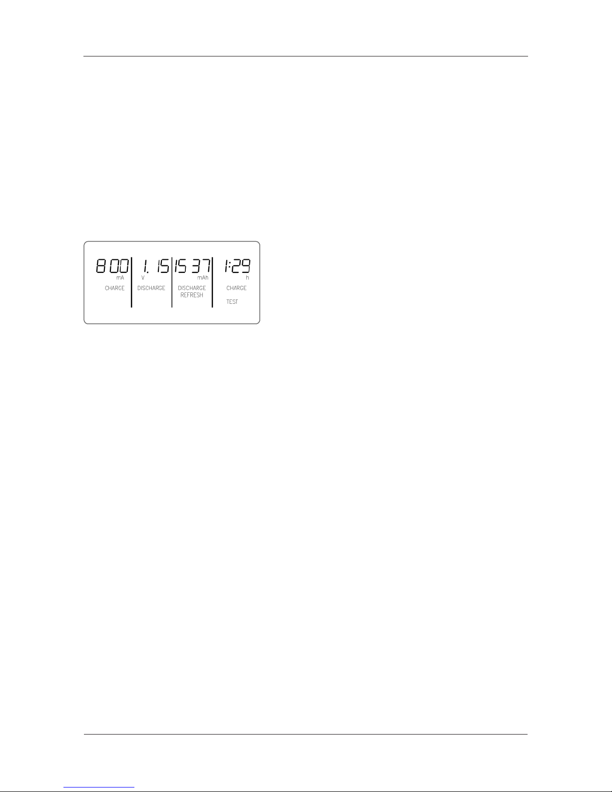
During the charging process, the pre-set
parameters are displayed as mentioned under
point 3 (DISPLAY). In addition, the chosen
charging program and the current process
(CHARGE or DISCHARGE) are shown. In the
illustration above you can see an example of the LCD display. This example
shows 4 different display modes and 4 different charging programs.
Charging 9V rechargeable batteries
One 9V battery can be charged, if no D-cells are inserted in the inner round cell
charging slots. When inserting the 9V battery, pay attention to the correct
polarity referring to the symbol in the charging slot. The LED charging indicator
illuminates red when the battery is inserted correctly. 9V batteries are charged
with a gentle current of c.15mA. After approx. 24 hours, the charge process
ends automatically and the LED illuminates green. The rechargeable battery is
charged and will be supplied with the trickle charge current so long as it
remains in the device. If the indicator flashes red, the battery has an internal
short circuit and should be disposed of.
Technical data
Input voltage external power supply: 100-240V AC / 50-60Hz
Input voltage car adapter: 12V DC (Do NOT use with 24V sockets)
Input voltage charger: 12V DC
Charging current for round cells: 400mA - 1800mA
Charging current for 9V batteries: 15mA
Maximum charging capacity: 11000mAh for round cells
300mAh for 9V block-style batteries
USB-charging socket: 5V/1000mA
Page 19

Dry Roof Pro’
19
Electromagnetic compatibility
Electromagnetic Emissions - European Union Directive 2014/30/EU:
Before operating this equipment, it is essential that the following risk assessment
be taken. As this equipment will produce an electromagnetic emission when
actually arcing down through a fault to earth, a risk assessment of the area in
which the unit will be used should be carried out.
For example, the equipment should not be operated where the
electromagnetic disturbance generated may hinder the operation of such
apparatus as:
●
Domestic radios and television receivers
●
Industrial manufacturing equipment
●
Mobile radio equipment; mobile radio and commercial radiotelephone
equipment
●
Medical and scientific apparatus
●
Information technology equipment
●
Domestic appliances and household electronic equipment
●
Aeronautical and marine radio apparatus
●
Educational electronic equipment
●
Telecommunications networks/apparatus. Radio & television broadcast
transmitters
●
Lights and fluorescent lamps.
The Directive also requires the above types of equipment to have an adequate
level of electromagnetic immunity from such emissions. However, it should be
borne in mind, when doing an assessment, that the directive applies to
equipment supplied or taken into service after 1st January 1996 and that the
equipment you are assessing, although legal, because of age, may not have
this immunity.
Common areas of risk are computers, critical safety equipment (fail/safe
electronics), supply cables, control cables, signaling and telephone cables
above, below and adjacent to the area where the tests are being carried
out. The users of pacemakers and hearing aids should also be considered.
Measuring and calibration equipment may also be susceptible.
Page 20

Instruction Manual
20
To make a comparison: an arc welder, when in use, would create
interference far greater than this type of tester. It would, therefore, be
reasonable to assume that if an arc welder had been used in the area
without problems, then a DC Pinhole Detector would be safe. However, it
would be unwise to use both pieces of equipment on the same site at the
same time as they may interfere with each other.
The test area itself should also be considered. For example, the layout of the
area would affect the distances, which the emissions would travel. Buildings
and metal structures would shield against, or reduce, emissions. If the tester
was being used inside a metal tank, for instance, the tank would act as a
very good shield. This would not, however, have the same effect if you were
testing a plastic tank. If you were testing the circumference of a metal pipe,
then the pipe would act as an aerial and transmit the emissions further than
expected. Remember that electromagnetic emissions travel in all directions
and can even be bent or deflected. Neighbouring works or sites should
also be taken into account; there may be equipment in use that could be
affected by your tester’s emissions.
Most of the time this type of tester will be used on outdoor sites and remote
from susceptible equipment, but the SITE SAFETY OFFICER should always be
consulted before any testing is carried out. This is particularly necessary where
electronically controlled equipment is being used.
Timing of the testing should also be considered as a means to avoiding
interference problems. Consider testing when all susceptible equipment in the
test area is switched off.
If your tester is only used in one area, then simple tests will ascertain where
the tester interferes with other equipment and these can be resolved by
scheduling the proper testing accordingly. Again, you should remember
neighbouring works.
The Dry Roof Pro’ is designed to meet the EMC directive therefore all leads
are optimum length. If longer leads are used, then they could transmit
similar to aerials and cause interference.
Page 21

Dry Roof Pro’
21
Always ensure that the tester and test piece is securely earthed because this
will reduce any interference generated by the spark. This also prevents static
build-up in the operator and thereby avoiding electric shock.
Wherever you are intending to use equipment of this type, on your site or a
customers, always obtain clearance from the company safety officer.
Page 22

Instruction Manual
22
EC Declaration of conformity
We:
Buckleys (UVRAL) Ltd
As manufacturer of the apparatus listed,
declare that the product:
Dry Roof Pro’
Is manufactured in conformity with
the following directives:
2014/30/EU
2014/35/EU
Authorised by:
J P Hoveman
CEO, Buckleys (UVRAL)
Ltd.
Page 23

Dry Roof Pro’
23
Contact details
Manufacturer: Buckleys (UVRAL) Ltd
Address: Buckleys
House
Unit G, Concept Court
Shearway Business Park
Shearway Road
Folkestone
Kent CT19 4RG, UK
Tel: +44 (0)1303 278888
Fax: +44 (0)1303 274331
Website: www.buckleysinternational.com
Distributor details
Page 24

Product registration
Thank you for choosing a Buckleys product,
we are sure it will provide you with many years
of reliable service.
Please register this product via Buckleys’
website and download the
Warranty Registration Certificate.
Register your product in 5 minutes
Once your product is registered, you will receive
the following benefits:
•
FREE
annual service & calibration reminders by email
•
Latest
industry news relating to your product
• Be the
first
to hear about our new products
We strive to improve the quality of our products and service.
Registering your product helps us monitor overall quality of our products,
service and dealer network. Additionally, if we ever need to contact you
regarding your product, we are able to do so immediately.
We will also send you annual service/calibration reminders by email to help
ensure your product is always in perfect working order.
To register your product, simply visit:
www.buckleysinternational.com/registration
...Complete the online form and click on SUBMIT.
5830-0044/DRP01/IM/ENG/V.10-18
 Loading...