

Page 1

BUCKINGHAM MFG.
P/N 101SR Rescue System Instructions / Warnings:
Read carefully, understand, and heed these and all included instructions, warnings, and cautions before using this equipment.
Failure to do so could result in serious injury or death.
Buckingham’s P/N 101SR has been designed to provide a means for a worker to rescue himself from a disabled aerial bucket or to rescue
a fellow worker from an elevated height. This system and any of its components must not be used for any other purpose.
This product has been tested to and meets applicable requirements of ANSI Z359.4.
The P/N 101SR Rescue System
• Two 24” Model ‘A1’ retrofit rappelling loops (1” wide webbing).
• DSD Plus Descender with properly threaded 1/2” diameter rope with a locking snap hook stitched to one end and figure ‘8’ stopper
knot opposite end.
• Model 50051 triple -locking carabiner attached to the descender.
• Model 4563 storage bag.
• Hook and loop fastener retaining strap.
DESCENDER:
Working load 130 to 310 lbs. (59 to 140 kg) as outlined by ANSI Z359.4. Additionally, this system can be used as follows:
• with a load of up to 440 lbs. (200 kg) as outlined by manufacture instructions and only in exceptional cases like an accompanied
descent (i.e. hurt man rescue). This method of rescue can only be used by rescuers specially trained in this technique.
• the 101SR system can additionally be rated for a single person load of 420 lbs. (190.5 kg) when used with an equivalently rated
harness and accessories.
In each of these cases, an additional breaking system must be used, and no impact loading tolerated. To add additional braking to
the system, the user must route the tail end of the descent line through the carabiner (Fig. 11) and control the rate of descent to
3.3 ft/sec. (1m/sec.) maximum by varying the angle of the descent line tail against the carabiner frame. This equipment is not
suitable for use in a fall arrest system. Note: It is important to read and understand the instructions and warnings for the
descender included with this product before use.
NOTE: TRAINING RECOMMENDATION
• For training purposes, it is recommended that a stopper knot be tied in the 1/2” diameter rope to aid in the prevention of the trainee
making contact with the ground in the event of improper use of the product. The stopper knot should be adjusted to a height so
that the trainee’s feet can only make slight contact with the ground, however, the stopper knot should be adjusted low enough that
the trainee can stand and disconnect.
• It is recommended that the trainer firmly grasp the descent line below the trainee. In the event of a free fall the trainer can pull
down on the descent line stopping the trainees descent.
PUTTING THE 101SR RESCUE SYSTEM INTO SERVICE
• This device is supplied with the soft lock feature (see Proper Packing bullets 9 & 10 on page 4 and Figs. 12 & 13 on page 5 of these
instructions). This soft lock should be used at all times except for when rappelling.
• Prior to use the 101SR Rescue System must be properly packed.
• The descender should be secured on the rope at the ideal location to ease the process of climbing out of the bucket. (see recommended
placement of descender Fig. 9 & 10 on page 4).
• The descender when packaged from the factory is placed on the descent line 36” from the anchor attachment snap.
• Anchor attachments and baskets differ so set up the location of the descender ideal for each truck.
• See proper packing section of these instructions for packing procedure.
• Suspend the storage bag from its steel mounting ring to a nylon bucket hook on either the inside or outside of the bucket (Buckingham
recommends our PN 2401-3).
Note: Prior to using the 101SR Rescue System it is necessary to determine the safest, easiest way of exiting the aerial bucket.
We suggest exiting over the top of the aerial bucket directly across from the anchor point.
USE INSTRUCTIONS FOR BUCKET SELF RESCUE
The following rappelling loops may be used for self-rescue: style ‘A1’, ‘A1’ retro (included in P/N 101SR), style ‘A2’, or the cross-over (“X”
style) harness with a web loop at the cross-over on the front of the harness (harness styles 3B, 3E, 3F). Rappelling loop styles A1 and A1
retro are to be used for self-rescue only.
• If using ‘A1’ retro rappelling loops, remove rappelling loops from storage bag.
• Slide the end of the rappelling loops with the 4” diameter loop under the harness straps at the point where the lower portion of the
shoulder straps cross the upper portions of the leg straps (Fig.1). Hitch the rappelling loops to the harness as shown in Fig.
contains the following components:
2.
P/N 230079 1 101SRANTH.Doc (Rev. 9-18-18)
101SR.DWG
Page 2
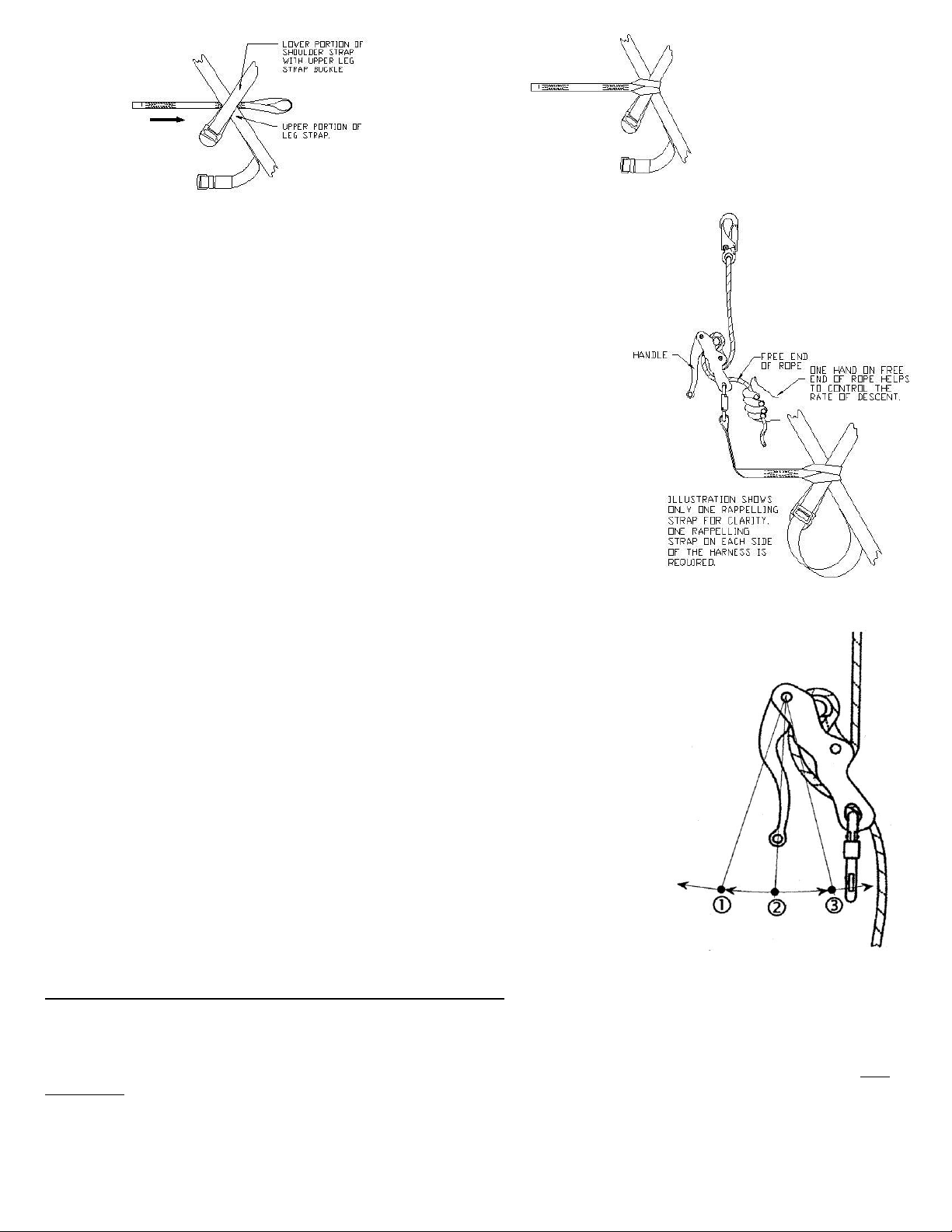
Fig. 1
Fig. 2
Fig. 3
Fig. 4
• Remove the 1/2” diameter rope with attached locking snap hook from the
storage bag and connect the locking snap hook to a suitable anchor point.
• Attach free end eye of each rappelling loop to the triple -locking carabiner
connected to the descender.
• Attach the descender to the rappelling loops on the harness with the handle of
the descender facing away from the body. This ensures the handle cannot
compress against the body. When installation is complete, assembly should
look similar to the illustration in Fig. 3.
Note: When using a “cross-over” (‘X’) style harness (style 3B, 3E, or 3F),
attach the triple -locking carabiner directly to the web loop at the cross-over
on the front of the harness.
• Drop the storage bag with remaining 1/2” diameter rope to the ground, being
careful not to come in contact with power lines or objects on the ground.
• Remove Hook and loop fastener retaining strap and remove soft lock on
descender. Test the function of the descender with the handle released
(position 1, Fig. 4) by pulling upward on the rope (the end with the snap hook)
to ensure the brake mechanism is working properly. Perform the same test
with the handle squeezed completely (position 3, Fig. 4). Squeeze the handle
to the midpoint (position 2, Fig. 4) while again pulling upward on the rope to
ensure the rope slides smoothly through the descender in this position. Re-tie
the soft lock so that the descender cannot be inadvertently depressed.
• Disconnect the shock absorbing lanyard from either the anchor point on the
aerial bucket or from the fall arrest attachment of the harness.
• Carefully climb out of the bucket.
• Once the user’s weight is supported by the descender, Remove Hook and loop
fastener retaining strap and remove soft lock on descender.
• Proper usage of the descender will allow descent at a controlled, safe rate. The
maximum speed of descent should not exceed 6.5 ft/sec. (2. m/sec). If the user’s
weight is in excess of 265 lbs. (120 kg), The maximum speed of descent should not
exceed 3.3 ft/sec. (1m/sec.). By increasing pressure on the handle, the user will
activate the braking position feature (position 3, Fig. 4) and the descent will be
stopped or considerably slowed. Releasing the handle completely (position 1, Fig. 4)
will also activate the braking feature. If additional braking is required, before starting
to rappel, the free end of the rope must be through the carabiner, vary the angle of
the tail of the descent line against the carabiner frame to control the rate of descent
to 3.3 ft/sec. (1m/sec.) maximum. Make sure the action of the rope will not unscrew
the carabiner’s gate. (Fig. 11)
• To rappel, slowly squeeze the handle toward the body of the descender with one
hand to the midpoint (position 2, Fig. 4) while the other hand controls the free end of
the rope to provide additional braking (tailing). Make a slow controlled descent to the
ground. If the need arises where the descent must be stopped, re-tie the soft lock so
that the descender cannot be inadvertently depressed.
USE INSTRUCTIONS FOR DUAL MAN BUCKET SELF RESCUE
To perform this type of rescue, an additional DSD Plus Descender with attached 50051 triple -locking carabiner is required in
addition to the standard 101SR Rescue system. You will also need an additional pair of Model ‘A1’ retrofit rappelling loops,
or a harness equipped with A1, A2 style rappelling loops, or the cross-over (“X” style) harness with a web loop at the crossover on the front of the harness (harness styles 3B, 3E, 3F). Rappelling loop styles A1 and A1 retro are to be used for selfrescue only.
If using ‘A1’ retro rappelling loops Slide the end of the rappelling loops with the 4” diameter loop under the harness straps at
the point where the lower portion of the shoulder straps cross the upper portions of the leg straps (Fig.1). Hitch the rappelling
loops to the harness as shown in Fig.2.
P/N 230079 2 101SRANTH.Doc (Rev. 9-18-18)
101SR.DWG
Page 3

A Dual Man Self Rescue can only be performed with one individual on the descent line at any given time. Ensure the first
user has completed their descent and have disconnected their DSD Plus from the descent line prior to performing any part of
this procedure.
• Once the first user is off the descent line weave the rope through your descender as shown in Fig. 8.
• Inspect the descender to ensure the rope is correctly woven through and the brake mechanism is functioning
properly.
• Open the triple locking carabiner gate and insert the descent line from the lower portion of the descender into
carabiner so it exits the carabiner on the same side as the handle of the descender (see Fig. 11).
• Recommended Placement of the descender outlined below eases the process of climbing out of the bucket.
A. If the rope goes across the bucket, extend the rope and place the descender approximately 1”-2” below the lip of the
bucket See Fig 9 & 10.
B. If the descent line drops straight down from under the bucket, locate the descender approximately 18” from the snap.
• Attach the descender to the rappelling loops on the harness with the handle of the descender facing away from the
body. This ensures the handle cannot compress against the body. When installation is complete, assembly should
look similar to the illustration in Fig. 3.
Note: When using a “cross-over” (‘X’) style harness (style 3B, 3E, or 3F), attach the triple -locking carabiner directly to
the web loop at the cross-over on the front of the harness.
• Test the function of the descender with the handle released (position 1, Fig. 4) by pulling upward on the rope (the
end with the snap hook) to ensure the brake mechanism is working properly. Perform the same test with the handle
squeezed completely (position 3, Fig. 4). Squeeze the handle to the midpoint (position 2, Fig. 4) while again pulling
upward on the rope to ensure the rope slides smoothly through the descender in this position.
• Re-tie the soft lock as outlined in the Proper Packing section of this instruction so that the descender cannot be
inadvertently depressed.
• Disconnect the shock absorbing lanyard from either the anchor point on the aerial bucket or from the fall arrest
attachment of the harness.
• Carefully climb out of the bucket.
• Once the user’s weight is supported by the descender, Remove hook and loop fastener retaining strap and remove
soft lock on descender.
• Proper usage of the descender will allow descent at a controlled, safe rate. The maximum speed of descent should
not exceed 6.5 ft/sec. (2. m/sec). If the user’s weight is in excess of 265 lbs. (120 kg), the maximum speed of
descent should not exceed 3.3 ft/sec. (1m/sec.). By increasing pressure on the handle, the user will activate the
braking position feature (position 3, Fig. 4) and the descent will be stopped or considerably slowed. Releasing the
handle completely (position 1, Fig. 4) will also activate the braking feature. If additional braking is required,
before starting to rappel, the free end of the rope must be through the carabiner, vary the angle of the tail of
the descent line against the carabiner frame to control the rate of descent to 3.3 ft/sec. (1m/sec.) maximum.
Make sure the action of the rope will not unscrew the carabiner’s gate (Fig. 11).
• To rappel, slowly squeeze the handle toward the body of the descender with one hand to the midpoint (position 2,
Fig. 4) while the other hand controls the free end of the rope to provide additional braking (tailing). Make a slow
controlled descent to the ground. If the need arises where the descent must be stopped, re-tie the soft lock so that
the descender cannot be inadvertently depressed
USE INSTRUCTIONS FOR HURT- MAN RESCUE FROM AN ELEVATED HEIGHT
To perform this type of rescue, the Harness must be outfitted with A2 rappelling loops or be of the cross-over style design
with web loop at “X” on front of the harness (style 3B, 3E, 3F). Rappelling loop styles ‘A1’ and A1’ retro are not to be
used for hurt-man rescue.
• Remove the descender with attached triple -locking carabiner from the storage bag and connect the carabiner to a
suitable anchor point.
• Connect the locking snap hook, stitched to the 1/2” diameter rope, to the victim’s rappelling loops or front web loop
(harness styles 3B, 3E, 3F),
• Test the function of the descender with the handle released (position 1, Fig. 4) by pulling upward on the rope (the end
with the snap hook) to ensure the brake mechanism is working properly. Perform the same test with the handle
squeezed completely (position 3, Fig. 4). Squeeze the handle to the midpoint (position 2, Fig. 4) while again pulling
upward on the rope to ensure the rope slides smoothly through the descender in this position.
• Pull up on the free end of the rope, taking up the slack between the victim and the descender.
• While holding onto the free end of the 1/2” rope which extends from the descender, cut the victim’s fall arrest lanyard.
P/N 230079 3 101SRANTH.Doc (Rev. 9-18-18)
101SR.DWG
Page 4
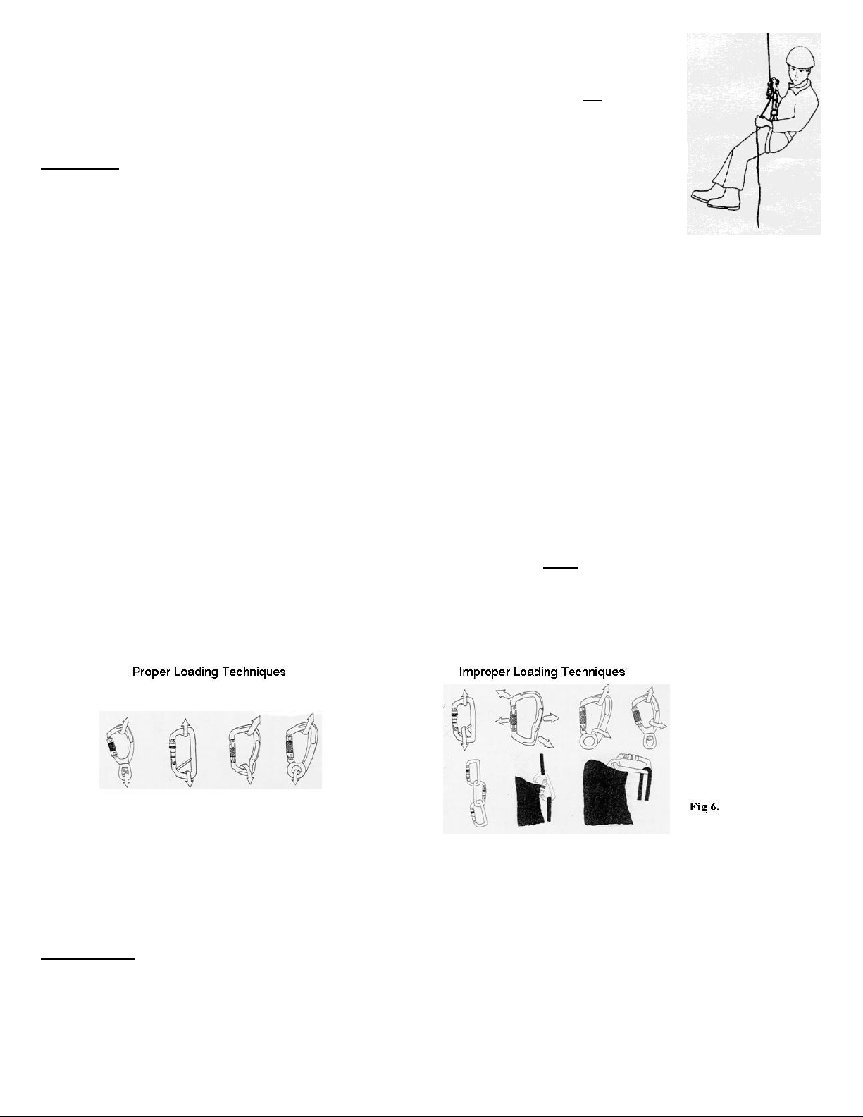
• Once the victim is being supported solely by the 1/2” diameter rope and descender, lower the
Fig. 5
victim to safety by squeezing the handle with one hand while using the other hand to control the
free end of the rope.
Warning: The ‘stop feature is a convenience for temporarily stopping on descent and not to arrest a
free fall.
WARNINGS
• Read understand and follow all instructions and warnings attached and/or packed with this
product before use.
• This equipment is intended for use by properly trained professionals only.
• Fall protection equipment, (i.e. fall arrest, work positioning belts, retrieval, suspension etc.) should not be resold or
provided to others for re-use after use by original user.
• Before use: 1. Ensure that rope is properly installed in the descender, 2. Rope is properly attached to anchor point, 3.
Operational test by loading with your bodyweight is performed.
• When descending, descent must be controlled with one hand on the free end of the rope and the other hand on the body
controlling the handle of the descender (see Fig.5). Failure to do so could result in serious injury or death.
• Ensure a stopper knot is tied in the end of the 1/2” rope to prevent the descender from slipping off the rope.
• Never attach another descender or descend on a rope that is being used for descent by another user.
• Anchor points must support a minimum of 5000 lbf. per attached worker and be
independent of worker support.
• Avoid rubbing of unit components against abrasive surfaces and sharp edges.
• Use this product only in combination with compatible equipment.
• Guard against debris which could block the action of the descender handle (pebbles, twigs, ice, snow, etc.).
• Guard against frozen conditions as excessive ice or snow buildup will adversely affect the proper operation of the
mechanical devices supplied with this system.
• Equipment subjected to impact loading must be immediately removed from service, destroyed and discarded.
• Always visually check that the snap hook / carabiner freely engages the anchor point and the keeper / gate is completely
closed. Never rely on the feel or sound of a snap hook / carabiner engaging.
• Be certain the snap hook / carabiner is positioned so that its keeper / gate is never load bearing.
• Ensure loads applied to carabiners are directed in the proper orientation. Proper and improper loading techniques are
shown below in Fig. 6.
• If descent is stopped , re-tie the soft lock on the descender as shown in Fig. 12 & 13.
• Never disable the locking mechanism on the snap hook / carabiner, punch holes in or alter a connecting device or any
part of this system in any way.
• Do not let any part of this system come into contact with any chemicals, corrosive materials, acids or basic solvents.
• Wearing gloves while using this product is highly recommended.
• Product covered under these instructions / warnings should not be resold / redistributed or re-used after use by original
user.
• Employer - instruct employees as to proper use, warnings and cautions before use of this equipment.
Maintenance
• Proper maintenance and storage of your equipment will prolong its useful life and contribute toward its performance.
Clean equipment with water and mild soap and allow to dry thoroughly without using excessive heat, lubricate as
necessary.
• Apart from visual examination of product before and after each use, it should be inspected at least twice
a year by an
authorized person.
P/N 230079 4 101SRANTH.Doc (Rev. 9-18-18)
101SR.DWG
Page 5
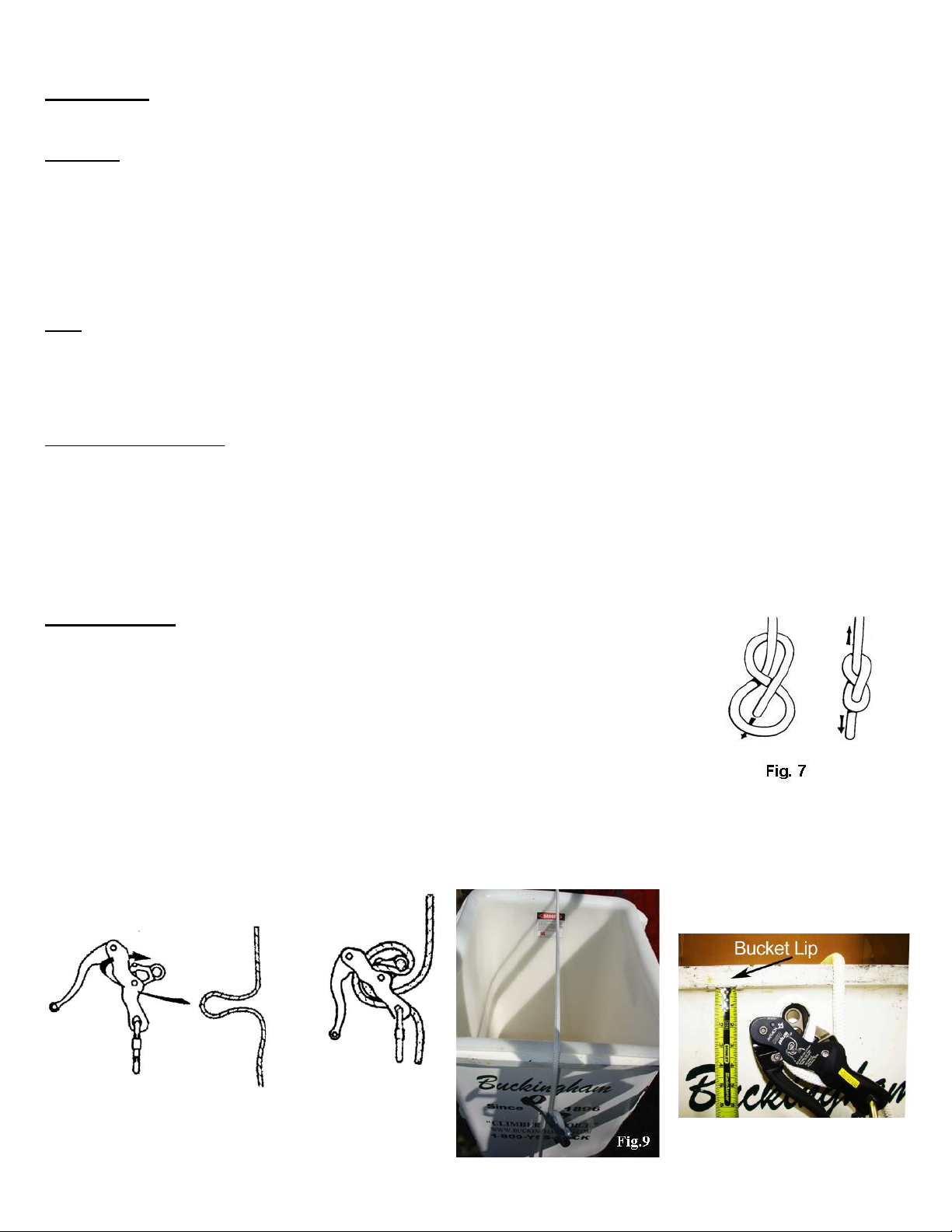
Fig. 10
Fig. 8
Fig. 8
• LUBRICATE lock mechanism and keeper on both sides of snap hook AT LEAST WEEKLY OR AS OFTEN AS
REQUIRED to maintain smooth operation (no binding) with light weight lubricant such as WD-40
®
INSPECTION
Prior and after each use, carefully inspect each component. It is also recommended all components be removed from the
storage bag and inspected every six months. The inspection should include, but not be limited to the following:
Descender
• Inspect for cracks, distortion, nicks or burrs and perform an operational test as outlined in “WARNINGS” above.
• Make sure the rope is woven through the descender correctly as illustrated on the unit and in these instructions.
• Inspect for proper operation of both the brake mechanism and the descent handle mechanism. Also make sure that the
rope slides smoothly through the unit when the handle is depressed to the midpoint (position 2, Fig.4).
• Some corrosion on the cam of the descender is normal, especially in a wet environment. If corrosion is evident, the cam
can be polished with a Scotch Brite pad; emery cloth, or equivalent. If severe corrosion or pitting is noticeable, remove
from service and notify your supervisor, safety director or Buckingham Mfg.
Rope
• Inspect for cuts, kinks, abrasions burns, broken fibers, chemical or physical exposures, excessive wear, discoloration,
swelling, or herniated rope (core popping through cover).
• Inspect stitched eye for excessive wear, abrasions, cut, broken, missing or unraveling thread or broken fibers where the
rope attaches to the snap hook eye.
Snap Hook and Carabiner
• Ensure locking device and keeper / gate operate freely and smoothly.
• Inspect for cracks, distortion, corrosion or nicks.
If any evidence of wear or deterioration as outlined is observed, immediately cease use, destroy the product, and replace it
with new equipment. Should any unusual conditions not outlined above be observed or you have reasonable doubt about a
particular condition, remove the equipment from service and notify your Supervisor, Safety Director, or contact Buckingham
Mfg. Co. for clarification.
Proper Packing:
• Ensure rope is completely dry before packing into the containment bag.
• Make sure a ‘figure 8’ stopper knot is tied in the free end of the 1/2” diameter rope (Fig. 7).
• Start by feeding the rope (the end with the ‘figure 8’ stopper knot) into the storage bag. This
ensures the rope will not become tangled when the bag is dropped from the bucket.
• Weave the rope through the descender as shown in Fig. 8.
• Recommended Placement of the descender outlined below eases the process of climbing
out of the bucket.
A. If the rope goes across the bucket, extend the rope and place the descender
approximately 1”-2” below the lip of the bucket See Fig 9 & 10.
B. if the descent line drops straight down from under the bucket, locate the descender approximately 18” from the snap.
• Inspect the descender to ensure the rope is correctly
woven through and the brake mechanism is
functioning properly.
• Open the triple locking carabiner gate and insert the
P/N 230079 5 101SRANTH.Doc (Rev. 9-18-18)
101SR.DWG
Page 6
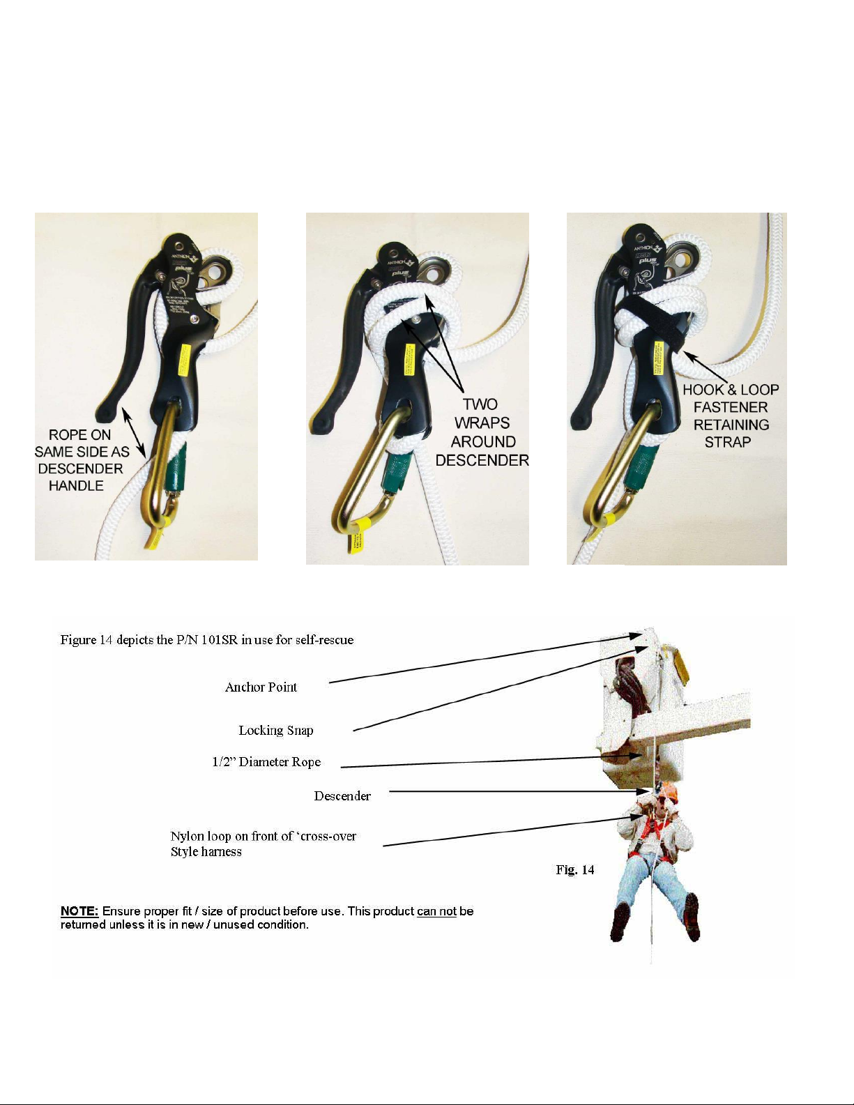
descent line from the lower portion of the descender into carabiner so it exits the carabiner on the same side as the
Fig. 11
Fig. 13
Fig. 12
handle of the descender (see Fig. 11 on next page).
• Wrap the descent line twice around the body of the descender so it is positioned between the cam of the descender and
the rope exiting the top of the descender (see Fig. 12 on next page).
• Secure the descent line to the descender using the Hook and loop fastener retaining strap (see Fig. 13 on next page).
• Place descender, remaining rope, and locking snap hook in the bag.
• Finally, place the rappelling loops, if the ‘A1 Retro style’ and instruction sheet in the bag and seal with the Hook and loop
fastener closure.
• Make sure the instructions are packed in the storage bag prior to each use.
P/N 230079 6 101SRANTH.Doc (Rev. 9-18-18)
101SR.DWG
 Loading...