


Modern Easel manual: The EMBIO – Electric Music Box I/O
by Joel Davel 11/28/23
The Modern Easel is here!!!! The Modern Easel – a 10-boat suitcase with the 208C and 218e-V3 has all the
features of the standard Easel but with an extra space for another module and a few extras built into the
module sized Electric Music Box I/O, the EMBIO.
1) USB, MIDI input and Euro compatible gate and pitch inputs for the 208C; The new inputs and outputs that
were part of the Easel Command
2) Sustain, USB, and MIDI output for the 218e; The inputs and outputs that were part of the latest LEM218.
3) A few CV utilities and a simple mixer
4) The Electric Music Box window: A simple power-on display or a wildcard spot for other utilities
Each is described below.
I/O:
1) 12V DC input and on switch: Center positive, 12 volt input. Use the included 70W AC
adapter (50W minimum, earth ground connected to barrel)
208C related:
2) Gate input takes 5v gate inputs and turns them into Buchla style pulses to the keyboard
pulse. (This pulse appears like an output at the keyboard pulse input banana.)
3) 1v/oct input with trim. This input goes to the keyboard pitch input.
4) 208C USB. This is the USB-MIDI input to the 208C. (Technically it goes to the 208MIDI
daughter board that is integrated into all 208Cs built as Easels.)
5) MIDI In: The 3.5mm MIDI input that goes to the 208C – 208MIDI daughterboard – by default.
(This can be reconfigured with jumpers to go to other MIDI inputs on alternate modules. See
appendix.)
218e related:
6) MIDI out: The 3.5mm MIDI output from the 218e.
7) 218 USB: 218e-V3 MIDI-USB input and output. (Also for programming firmware updates.)
8) “gnd”: The grounding input necessary for connecting common grounds between Buchla
systems or for the ground strap when your body needs better direct grounding with the 218e
for playability.
10) Sustain: A sustain pedal input for the 218e. The 218e auto-detects the polarity of the
sustain pedal on boot up.
Audio:
Mixer and audio
The “main” output is the output the 208C master out.
If the “mix” jack output on the far right is empty then it is also a mix of
the master out with in1, in2, and inU. The mix is normalled to the
main out as graphically shown by the circled “N”. The mix is mono
and is sent equally to sides Left and Right.
But if there is a cable inserted into the “mix” jack, then the mix of in1, in2, and inU
is disconnected from the main mix and only sent out the “mix” jack. This is useful for
mixing together two signals such an external input and mixing it with the direct out the
c.osc or m.osc to them put into a gate instead having to decide on either or.
The “inU” jack is a unity gain input with no potentiometer. This input can also be set by
jumpers to disconnect from the mix and send exclusively to another input such as a utility
created for the wildcard window. (See headers descriptions for jumper selection.)

The Control Voltage (CV) section:
The right side of the EMBIO has a set of banana jacks that extend the “patch field” of the 208C.
Like the 208’s patch field, it also has numerous connections that are a “shorting bar” distance apart
and therefore connections can be made cleanly and quickly either up and down or on a diagonal.
CV to pulse conversion: This can be used to turn an LFO into an autopulser or to
take the 208 Pulser output (which is a sawtooth) and turn it into a pulse that can be
easily read by the 218e-V3 pulse input. (It’s also a way of creating a 5v
pulse/squared wave from a triangle input.)
Slew in and out: The positive slew will affect the positive going
signals and the negative slew with affect negative moving signals.
Uses for slewing might include slewing the random CV’s, pulser
CV, pulses or even pitch CV’s. It can shape otherwise square
signals or simply extend responses.
LFO: A VLFO – very low frequency oscillator. This triangle wave LFO cycle is
over 30 seconds at its slowest and danceable at its fastest. The blue LED is a
direct indication of the CV output just like all the outputs on the EMBIO.
CV mix/crossfade:
The “AB” blue banana is the mix output. “B in” and “A Attv in” are the
inputs. The mix is controlled by the “xfade” knob. This CV mix is a
crossfade; it is not additive. The crossfade can be controlled by the
knob or the CV input. The knob position does add with its gray banana
CV control input. To get the full range of 0-10v CV control, turn the
knob all the way to A.
Alternate card slot: This opening is for 200e users who might want to add a
card slot for a memory card or firmware card. The card slot cable connects to
header H1. Request memory card connector from Buchla USA or your authorized dealer.
The opening could instead potentially connect a 223TS or LEM218 through an adapter cable.
More about the CV mixer
Dynamic attenuation: To control the attenuation with a CV, leave the A input open,
then the knob to A and use a crossfade input to move the mix of the A input
toward B.
Some uses include a velocity CV controlled envelope: Taking the velocity output of
the 218e-V3 and putting it into the crossfader CV input and then putting the 208 EG output CV into
the B input to create out a velocity controlled envelope.
Other examples: Use put the pressure in the xfade and a slewed random in the B-input to create a
controlled random CV or put the 218e pulse out into the B input and pressure into xfade with mix
set in the middle to create a dynamic CV for gates without either velocity a envelope generator CVs.
Note that the “xfade” input is a shorting bar distance from the LFO for an easy connection to it or
the “B in”.

The A input Attenuverter
The A input – and only the A input -- goes through an attenuverter.
But how does the attenuverter work?
There are two pots involved. The center 0v-5v knob position only matters when
you either attenuate the or invert the signal. If you leave the Attv input all the way
up, then the offset of the center makes little difference. Normally you’d leave the
center offset at 0v.
Because If you want to simply attenuate a signal like a sine wave CV:
Leave the pot at 0v and attenuate. In these examples, the orange line is the A input; the blue line is
the output.
If you start
to bring up
the center
voltage to 5v you get this offset:
The main reason to bring up the center voltage is to offset inversion so that the signal remains a
positive voltage that inputs of Buchla modules expect and because once you reach the center or
invert, you get almost nothing because the output is protected from going below -0.3 volts
But if you invert then turn the center knob up
you only get inverted output of just the lower
voltage signal
At knob position 5v you get full inversion of a positive 0 to 10v
into a positive 10v to 0v signal.
Example: Set it at
5v if you simply
want to reverse the
direction of a
sawtooth wave.
Likewise, when you mix signals, if you
choose to invert a signal, then you might
want to play with the center of the
inversion.
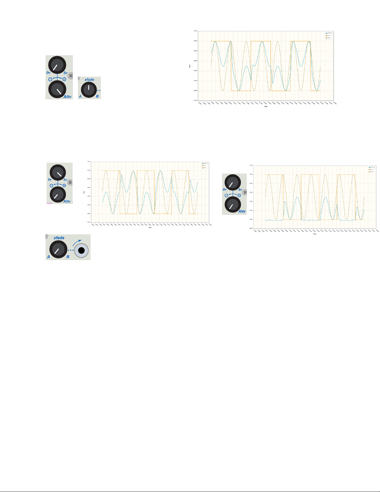
Here’s a square wave in the A
input mixed equally with
a sine wave in the B
input.
But when inverted the center reference for the inversion still influences/offsets the mix that then
gets clipped at around 0v. This is because the inverted signal will mix before the 0v protection
In these examples, the orange line is the A input; the brown line is the B-input and the blue line is
the output.
And now when the inverted A input has a signal but still results in 0v out when
turned to A, you can then dynamically xfade in a mixed signal to create a more
unique envelope.
Try an Envelope controlled LFO!
As a mixer of two 10v CV signals into one mixed 10v signal such as to add just a little random CV
to another CV.
Note about pitch accuracy: While these A and B inputs can work well for pitch in a limited range,
it’s not pitch perfect. It was designed with envelopes in mind. Results may vary.
For more accurate mixing for pitch would require a simpler current summing or simpler xfade circuit to get more
consistent results. There are trims for gain and one for bias of the A input.
Trimpots are set at the factory:
RB1 affects the bias of input A; R53 trims the gain of both inputs A and B.
R40 trims the gain of the slew circuit.
Enjoy the Modern Easel! If you have more technical questions about cabling
and other options, see below.

APPENDIX:
First a couple answers:
Can the EMBIO be mounted in a different module location?
Yes, but some cable lengths may need attention and it may not be practical.
Can I use the oval holes for jack adaption?
Yes. Break off the side cover of the Lit Electric Music Box graphic board – it’s scored for that – and
use the open holes for an adapter for something like a banana to 3.5mm connection, a
potentiometer, or audio jacks.
Ream one of the holes open enough for a BNC lamp connection using the 12v from the PSU board.
Consider using the .125” holes for mounting screws or additional LEDs
Can I power more than 9 modules with the EMBIO? It is designed to support up to 10
modules. But if the modules are power hungry it might only support 8 or 9. If they are power
efficient it could power 12 modules, but we choose not to configure it that way. The 218e or
LEM218 is only one module worth of power so the LEM218 could be powered from this case.
The EMBIO wildcard window.
This has the lit up Electric Music Box image. If it’s fully lit, then all the voltages are present. A
flickering of the stem of the note indicates internal bus activity.
Potential alternate uses of the window:
A photo of your significant other who would rather you pay more attention to them than spend
hours on your grand creative ideas.
Program Manager alternate control mounting. The
Embed kit includes hardware needed. See Program
Manager embed documentation.
Developer options. (Buchla is not responsible for irresponsible development.)
The window is a common 2.4” TFT size opening good for a display such as for a tiny oscilloscope.
How about a joystick or X-Y pad using the two holes to mount banana jacks with the X-Y outputs.
+-15v, 5v, 3.3v and i2c is provided on the 2mm cable.
There is a labeled pad for 12v on the PSU board.

PSU board cable connections
and header descriptions:
H14: h-Power output to CVP board and window
power through 2mm 10pin cable.
H10: 208C/208MIDI USB, MIDI, gate and 1v/oct
connections through the 10pin cable.
H26A H26B: 26pin power and i2c connections to
208C and power distributor on lower boat
H7: 218eV3 USB, MIDI and sustain pedal
connection through 10-pin cable.
Other Headers and jumpers on PSU board:
H18: “Audio”; Left and Right Audio to main ¼” output. (See CVP board connections)
GT208 and 208CV1:
Default jumpers for 1v/oct and gate inputs to go to 208MIDI/208C.
H16: 2pin alternate header for the gate and 1v/octave connections to a
208C without the 208MIDI daughterboard.
218CV: For alternate use of the gate and 1v/oct 3.5mm jacks for 218e-V3
instead of 208C. This requires that the jumpers from GT208 and 208C1V
move to GT218 and 218_1v.
208DIN jumper: jumper for MIDI to the 208C/208MIDI
This is the required default for 3.5mm MIDI In connection.
MDIN jumper only for 3.5mm MIDI input to the 218eV3
That is not typical unless a non-208C is in the case.
H15: Alternate direct h-power for 218e-V3 (Normally use power distributor board on lower board
for 218e.)
H11: for very rare use with sustain to direct gate control connect pins 1-2 or pin 2-3 depending of polarity.
H2: for very rare use to shunt the input of the sustain pedal for normally closed sustain pedal use if using H11 and direct
sustain control of the gate input.
Alternate headers for use with 200e modules:
Note: Both H7 and H10 can also be used for 225h or 226h USB if not use for Easel purposes.
H8: “225e/h”; 10pin 225e or 225h 3.5mm/DIN MIDI input (no jumpering required)
H3: “226h”; 3-pin 226h DIN/3.5mm output
H6: “218eV2”; 6pin older 218e 2013/v2 MIDI and sustain. (no jumpering required)
H1: to connect the Memory/Firmware card adapter board.

Audio connections on the on the CVP board:
H4 and H5: H4 and H5 must be jumpered to pins 2 and 3 (labeled “UMIX”) for normal
unity gain mixer input of the “inU” input.
The “TO MAIN” header connects to the EMBIO-PSU board H18
H7: 3pin audio output to main ¼” jacks
Audio from the 208C (or other outputs like a 206e or 207e) will mix with the mixer on
the EMBIO when nothing is inserted into the output jack.
The cable from the 208C audio out (or 206 or 207e) goes to the “208 AUDIO” header
H8: 3pin audio input from 208C
Alternate redirection of the unity gain “inU” input.
Originally designed with an oscilloscope in mind, use “U-opt”/H3, if you want to an
audio jack and banana jack connection to this header. The audio connection will be
from “InU”. When nothing inserted in “inU” the jack will get the Left master audio
from the 208C.
The BANANA test point on the audio jack board will also connect to a pin on this
header if something is soldered to it.
Jumpering: If H5 is jumpered pins 1&2, then H4 pins 1 and 2 are jumpered for inU’s
shunt connection to left main audio. (If H5 was jumpered to pins 2&3 there’d be
feedback though the shunt.)
 Loading...