

Page 1
BÜCHI Vacuum Controller B-720
Contents
Contents
1 Scope of delivery 2
2 Safety 3
3 Function 5
4 Putting into operation 7
5 Operation 10
6 Maintenance 15
7 Taking out of operation 17
8 Replacement parts 18
9 Appendix 23
Read these operating instructions carefully before you use the
Büchi Vacuum Controller B-720. Keep these instructions in a
safe place preferably close to the Vacuum Controller for quick
reference whenever required.
Chapter 2, Safety contains important notes concerning safety.
It is imperative to read these notes in order to operate the Vacuum
Controller safely.
Contents are subject to change without prior notice. No part of
these operating instructions may be reproduced in any form or
be processed, duplicated or distributed by electronic or optical
means without the written permission of Büchi Labortechnik AG.
All rights reserved. Copyright © Büchi Labortechnik AG, 1995
en, Version D (24 pages) Order No.
B-720 Instructions 96601
1
Page 2
1 Scope of delivery
BÜCHI Vacuum Controller B-720
1 Scope of delivery
Description
Models: Order No.
Büchi Vacuum Controller B-720 230 V 34860
Büchi Vacuum Controller B-720 120 V 34960
Table 1: Scope of delivery
Enclosed items:
1 D12-16 cross clamp, complete 27347
1 GL 14 hose connector, complete 32885
1 Instructions in the following languages:
German 96600
English 96601
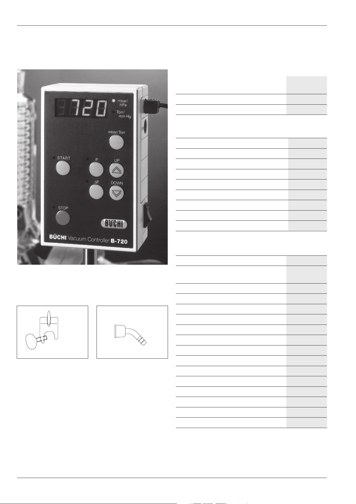
Figure 1: General view of the B-720
Figure 2: complete D12– 16 cross
clamp
Figure 3: complete GL14 hose
connector
French 96602
Italian 96603
Spanish 96604
1 Packaging, complete
Table 2: Enclosed items
Optional accessories:
Water jet pump B-764, complete 31358
Water jet pump B-767, complete with 31357
cooling valve
Cooling water valve, complete 31356
Two-way solenoid valves, 24 VDC:
Type for 1-liter Rotavapor 31353
Type for 20-liter Rotavapor 31354
Type for 50-liter Rotavapor 31355
Büchi Switch-box B-745:
Type CH 36410
Type D 36411
Type International 36412
Adapter cable 31225
U.S. adapter cable 33369
Woulff bottle trap, PLASTIC+GLAS 25519
Bottle clamp 11152
Rod 32008
Table 3: Optional accessories
2
Page 3

BÜCHI Vacuum Controller B-720
2 Safety
2 Safety
The Vacuum Controller is built in accordance with the art of
engineering and the recognized rules of safety.
Nevertheless, it can still be a source of risks and hazards:
• if used by persons with insufficient training.
• if used for purposes other than that for which it is intended.
2.1 Symbols
Stopp
Information about hazards which can lead to extensive material
damage or cause serious or potentially fatal injury.
Warning
Information about hazards which can be harmful to your health
or lead to material damage.
Please note
Information about technical requirements. Non-observance can
lead to malfunctions, inefficiency and possibly even lost production.
2.2 Requirements to be met by the customer
The Vacuum Controller may only be operated by persons
capable of comprehending the hazards that can arise during
its use.
2.3 Proper use
The Vacuum Controller is designed and built for laboratory
operation. It is to monitor and control vacuum levels over a
working range from 0 mbar to atmospheric pressure.
Typical applications include:
• Distillation apparatus, especially rotary evaporators
• Vacuum filtration
• Vacuum impregnation
For the Vacuum Controller to be used properly, it must also be
cleaned and maintained with routine care.
3
Page 4

BÜCHI Vacuum Controller B-7202 Safety
2.4 Improper use
Any use other than those already listed and any application that
does not conform with the technical data is deemed to be a
case of mis-use. The customer shall bare sole responsibility for
any damage caused by such mis-use.
The following applications in particular are prohibited:
• Use as a calibrating unit for other equipment
• Use as a barometer
• Use in hazardous duty areas or areas designated as Explo-
sion Proof
• Operation in overpressure
·
2.5 Safety measures
It is imperative to wear personal safety items such as goggles,
protective clothing and gloves.
These operating instructions are to be considered part of the
B-720 Vacuum Controller. They must always be kept near the
unit so operating personnel can consult them at any time.
The customer is responsible for instructing subordinate
personnel. These operating instructions can be ordered in other
languages for this purpose.
The customer shall notify the manufacturer immediately of any
safety incidents involving the B-720 Vacuum Controller.
2.6 Safety elements
A built-in ventilation valve vents the system automatically upon
reaching a level of overpressure in excess of 1400 mbar.
4
Page 5
BÜCHI Vacuum Controller B-720
3 Function
3 Function
The B-720 keeps a selected level of vacuum constant. It
automatically compensates any loss of vacuum in the evacuated
system by re-adjusting the vacuum to the set pressure level. It
does so by actuating a two-way valve in the vacuum line or by
directly switching the vacuum source on and off.
Solvent can be condensed with hight efficiency if the optimum
vacuum level is selected for the specific solvent. This results in
an immense reduction of solvent through the vacuum pump or
in a laboratory’s waste water.
You can also use the B-720 to control the flow of cooling water
during distillation. This is done by actuating a cooling water valve.
Water savings of up to 95% are possible this way.
All B-720 models are delivered as standard with an aeration
valve, also used for purging with inert gas, a cross clamp for
mounting on a stand, and a GL14 hose connector for connecting
the vacuum hose.
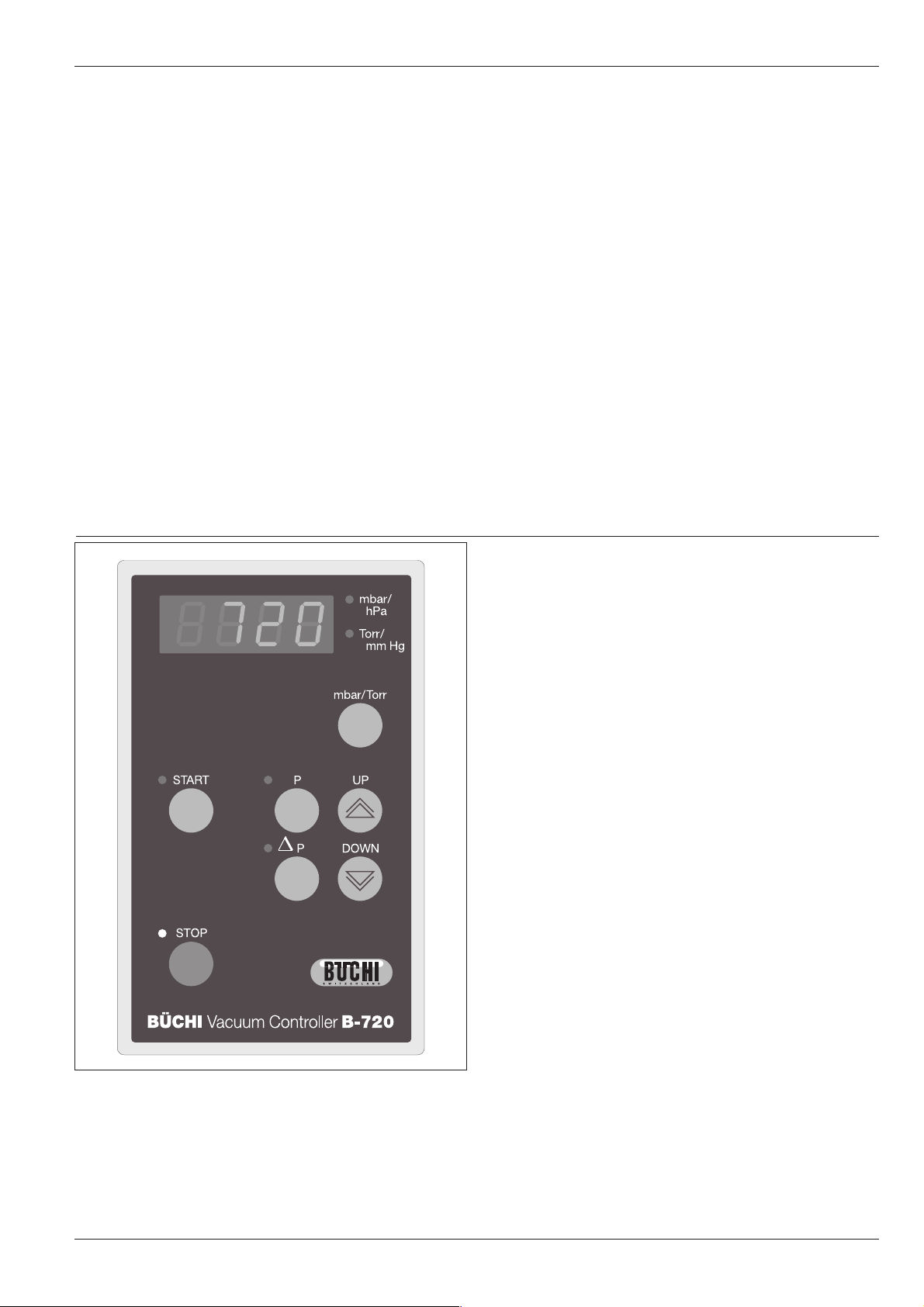
3.1 Functions of the various keys
«P» You can set the desired value of your choice with
the arrow keys. If no key is pressed within 3 seconds,
the display will switch to its initial state and the
setdesired value will be saved automatically.
«욼P» You can set the desired hysteresis in mbar or Torr
with the arrow keys. If no key is pressed within 3
seconds, the display will switch to its initial state
and the setdesired value will be saved automatically.
«UP» Press this key to increase the desired value.
«DOWN» Reduces the pressure or hysteresis during distil-
lation.
«mbar/Torr»Switches the LED display from mbar/hPa to Torr/
mm Hg.
«START» Starts the evacuation process.
«STOP» Stops the vacuum process. The system is ventilated,
but the cooling water valve does not close until 5
minutes later. Press twice for the cooling water to
be switched off immediately.
Figure 4: The keypad on the B-720
5
Page 6

3 Function
BÜCHI Vacuum Controller B-720
P
407 mbar
400 mbar
0
0
Figure 5: Manual hysteresis
P
412 mbar
400 mbar
0
0
Figure 6: Automatic hysteresis
1
1
3.2 Manual hysteresis
The tolerance range of the operating point can be selected
automatically as well as manually.
2
7 mbar
3
Example:
Nominal pressure 400 mbar, manual hysteresis 7 mbar.
The pump evacuates to the desired pressure of 400 mbar,
the two-way valve closes or the vacuum pump switches
off.
t
The pressure rises by 7 mbar.
The pump evacuates again to the desired value.
3.3 Automatic hysteresis
The automatic hysteresis function works by continuous (linear)
degression.
2
12 mbar
• 30 mbar for a desired value of 1000 mbar
• 1 mbar for a desired value of 2 mbar
Example:
Nominal pressure 400 mbar, automatic hysteresis 12 mbar.
The pump evacuates to the desired value of 400 mbar,
the two-way valve in the main vacuum line closes or the
vacuum pump switches off.
t
The hysteresis tolerance range for this desired value
amounts to 12 mbar.
6
Page 7
BÜCHI Vacuum Controller B-720
4 Putting into operation
4 Putting into operation
Check that the voltage of the power supply corresponds to the
value marked on the B-720 rating plate.
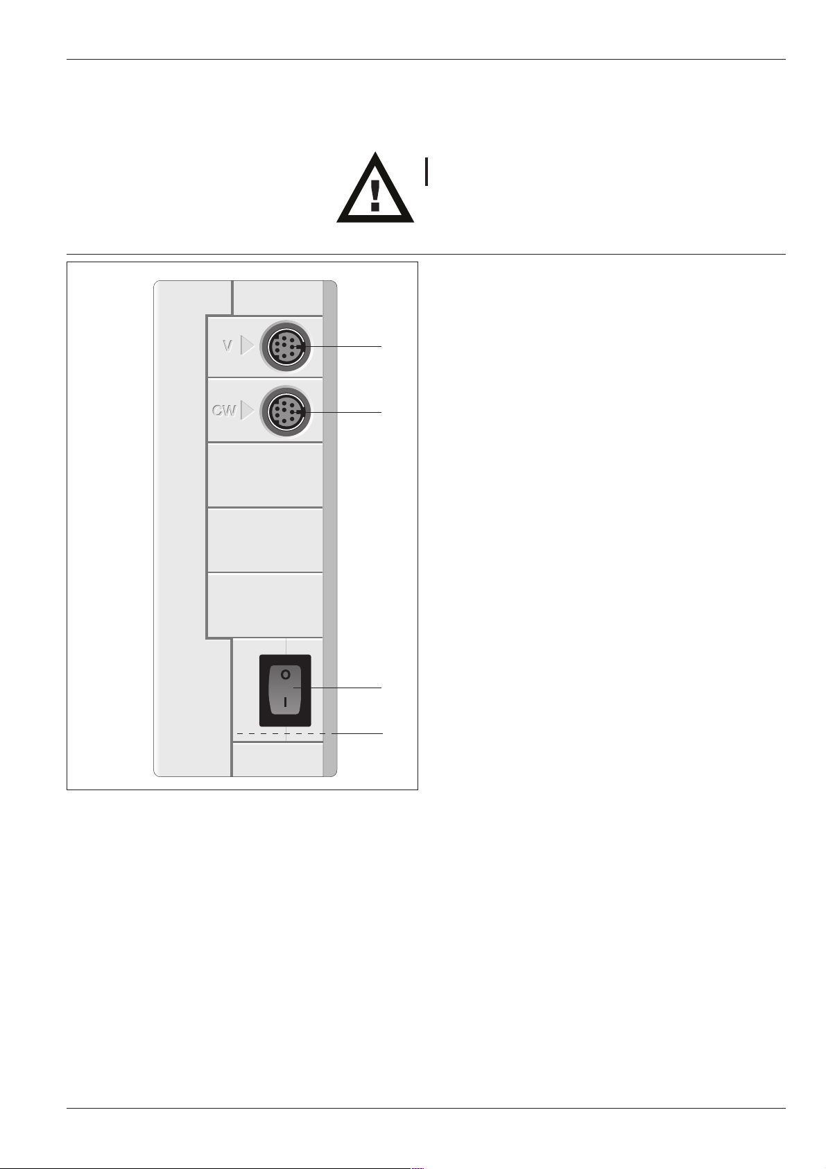
4.1 Connections on the side
V Valve connection
V
CW
CW Cooling water valve connection
Power switch
Fuse (at the left-hand side of the housing)
Figure 7: The right-hand side of the B-720 housing
7
Page 8
4 Putting into operation
BÜCHI Vacuum Controller B-720
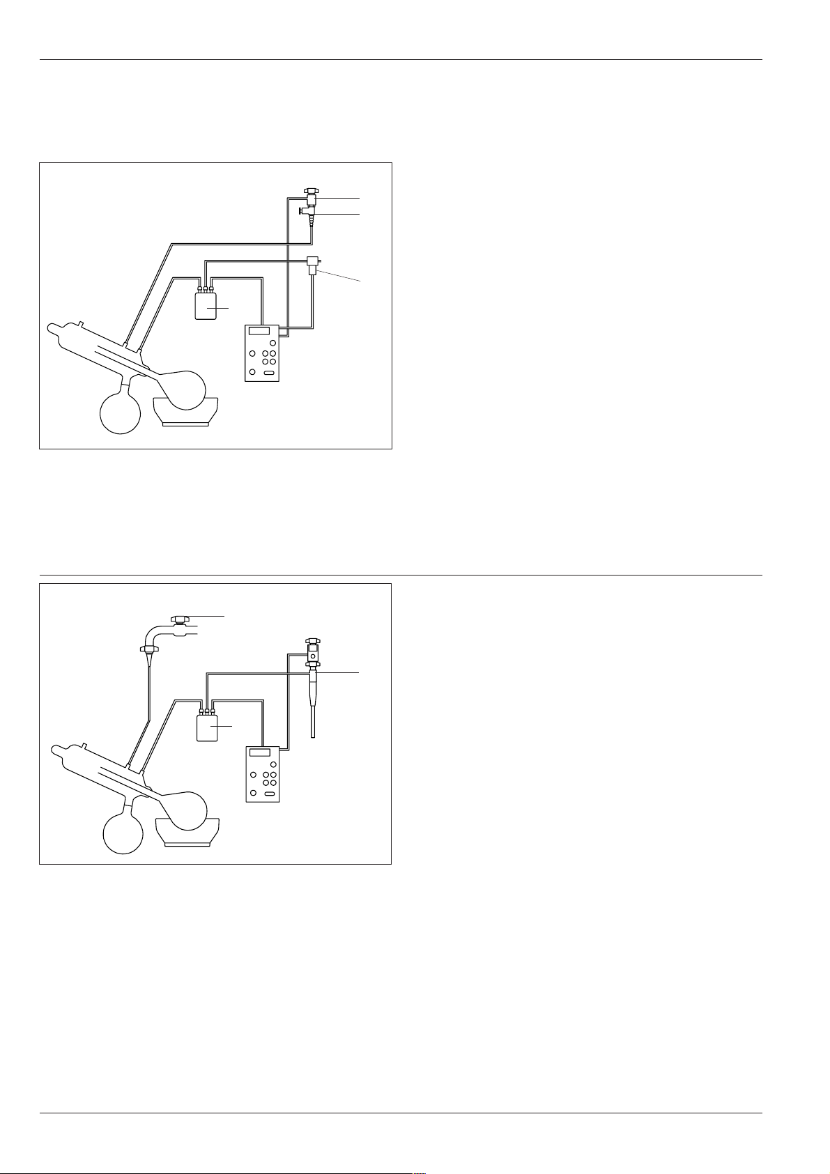
Figure 8: The B-720 with a two-way valve and a cooling water valve
4.2 Installation with a two-way valve and a
cooling water valve
• Install the two-way valve between the vacuum pump
and the woulff bottle .
• Connect the two-way valve to the socket V.
• Screw the cooling water valve onto the water faucet
(remember the seal and screen).
• Insert the cooling water valve plug in the socket CW.
• Connect the cooling water hoses.
• Connect the B-720 to the power supply.
• Switch on the B-720.
• Turn the water faucet on and use the needle valve to
adjust the flow through the condenser.
Water faucet
Woulff bottle trap
Needle valve
Cooling water valve
Vacuum pump
Two-way valve
Figure 9: The B-720 with a B-764 water jet pump
4.3 Installation with a B-764 water jet pump
• Attach the B-764 water jet pump to the water faucet.
• Insert the valve plug in the socket V.
• Fully open the water faucet .
• Connect the cooling water hoses.
• Connect the B-720 to the power supply.
• Switch on the B-720.
• Turn on the water faucet .
Water faucet
Woulff bottle trap
B-764 water jet pump
Water faucet
8
Page 9

BÜCHI Vacuum Controller B-720 4 Putting into operation
4.4 Installation with a combination water jet pump
B-767
The water jet pump B-767 has a built-in cooling water valve.
• Attach the water jet pump B-767 onto the water fau-
cet .
• Insert the valve plug in the socket V.
• Connect the cooling water hoses.
• Connect the B-720 to the power supply.
• Switch on the B-720.
• Turn the water faucet on and use the needle valve to
adjust the flow through the condenser.
Water faucet
Woulff bottle trap
Needle valve
B-767 Water jet pump
Figure 10: The B-720 with a B-767 Water jet pump
Figure 11: The B-720 with a vacuum pump, a B-745 Switch-box and a
cooling water valve
4.4 Installation with a vacuum pump, a B-745
Switch-box and a cooling water valve
• Connect the B-745 to a socket-outlet.
• Plug the vacuum pump into the B-745 with the power
cable.
• Place the non-return valve in the vacuum line leading to
the woulff bottle trap .
• Plug the connecting cable from the B-745 into the socket
V of the controller.
• Attach the cooling water valve onto the water faucet .
• Insert the valve plug in the socket CW.
• Connect the cooling water hoses.
• Connect the B-720 to the power supply.
• Switch on the B-720.
• Turn the water faucet on and use the needle valve to
adjust the flow through the condenser.
Water faucet
Woulff bottle trap
Needle valve
Cooling water valve
Vacuum pump
Büchi Switch-box B-745
Non-return valve
Connecting cable
9
Page 10

5 Operation
START
∆P
BÜCHI Vacuum Controller B-720
5 Operation
The unit is not splash-proof.
5.1 Controls on the membrane keypad
Set desired pressure «P».
mbar/
hPa
Torr/
mm Hg
mbar/ Torr
P
UP
DOWN
Set hysteresis «욼P».
Increase the displayed value, ventilate the system during
distillation «UP».
Decrease the displayed value, lower the pressure during
distillation «DOWN».
Change the display from mbar or hPa to Torr or mmHg
«mbar Torr».
Start the distillation process «START».
Stop the distillation process «STOP».
STOP
B†CHI Vacuum Controller B-720
BÜCHI
Figure 12: The membrane keypad on the B-720
SWITZERLAND
5.2 Normal operation
1. Set the power switch to ON.
2. Use «P» with «UP» or «DOWN» to select and set the desired
value of your choice.
3. Use «욼P» to check the hysteresis and change if necessary
with «UP» or «DOWN».
4. Press «START».
10
5. Distillation begins.
6. Press «STOP»; the unit is ventilated.
7. Set the power switch to OFF; the last set point values entered
will be saved.
Page 11

BÜCHI Vacuum Controller B-720 5 Operation
5.3 Detailed description of the various functions
The numbers used in the following examples were chosen at
random and serve only to explain the functions.
Action Display Function
Switch on «On» switch 957 • Displays actual system pressure
the unit (current system pressure) • Ventilation valve open
• Cooling water valve open for approx. 5 min., but can be closed
by pressing the «STOP» key
Set desired «P» Press e.g. 147 • Displays the desired pressure which can be varied with the
pressure (desired pressure) «UP» and «DOWN» keys (0– 1400 mbar)
• If no entry is made within 3 sec., the displayed value will be
saved automatically and the display will return to its initial state
• The desired value can be changed at any time
Hysteresis «욼P» H 10 • Displays the hysteresis key which can be varied with «UP»
and «DOWN» keys (1– 100 mbar and A)
HA • Automatic hysteresis, i.e. 30 mbar at 1000 mbar, infinitely
reducible to 1mbar at 2 mbar pressure
• If no entry is made within 3 sec., the displayed value will be
saved automatically and the display will return to its initial state
Destillation «START» 957 • System is evacuated to the preselected desired value and is
controlled there within the set hysteresis
147 • LED «START» lights up
(current system pressure) • Cooling water valve opens
Stop «STOP» 957 • Aborts the control function
(current system pressure) • System is ventilated (ventilation valve remains open)
• The cooling water valve remains open for approximately 5 min.
• Press «STOP» twice and the cooling water will switch off
immediately
Table 4: Description of the Functions
11
Page 12

5 Operation
5.4 Hold state
After distillation is started, you can use the arrow keys to
intervene in the automatic control sequence at any time. Pressing
«UP» causes an immediate increase of the system pressure
(the system is aerated), pressing «DOWN» decreases the system
pressure.
Action Display Function
Hold state «ON» switch 957 • The unit is switched on.
(current system pressure)
«START» 957 • Distillation is started.
147
(current system pressure)
«UP» 387 • The evacuation process is interrupted and the LED of «START»
(current system pressure) flashes.
• Hold state.
Keep key depressed • The system pressure is adapted as long as the key is kept
depressed, i.e. while «DOWN» is pressed, the pressure will
be lowered continually; press «UP» and the ventilation valve
will be opened.
• After you release «UP» or «DOWN», the new pressure will be
controlled with the saved hysteresis.
• Press briefly on «START» to continue the function that was
active before the interruption.
Table 5: Hold state
BÜCHI Vacuum Controller B-720
12
Page 13

BÜCHI Vacuum Controller B-720 5 Operation
5.5 Working example
The values in the following example apply for the distillation of
ethanol. For the values of other solvents, please consult the
table at the end of this section. Check the following items before
each distillation:
• Cooling water connected
• All the electrical connections OK
• All the hose connections OK
• Vacuum source connected
Action Display Function
Distillation «ON» switch 957 • The system pressure is displayed.
of ethanol (current system pressure)
«P» 147 • The desired pressure is displayed and can be varied with
(desired pressure) «UP» and «DOWN» (1 mbar-atmospheric pressure).
«욼P» H 16 • The hysteresis displayed.
«DOWN» key until H 5 • Set hysteresis 5.
desired hysteresis is set
«START» 957 • The system is evacuated to the preselected desired value of
72 72 and is conntrolled there within the set hysteresis of 5.
(current system pressure)
«UP» Current system pressure • System is ventilated for as long as the key is kept depressed
«START» Current system pressure • The system is evacuated to the initial set-point value
«STOP» 957 • The system is ventilated (the ventilation valve remains open)
Press «STOP» 2 x 957 • Press «STOP» twice for the cooling water to switch off
briefly (current system pressure) immediately
Table 6: Working example
If there is any foaming or severe splashing, it is possible to
intervene directly with «UP»/«DOWN» Hold state.
• When the key is released, the pressure is adjusted to the new
set-point value.
• The LED «START» flashes.
• When «START» is released, the pressure is adjusted to the
current value.
• The LED «START» lights up.
Press the «START» key for the distillation to continue, i.e. the
system will operate at the set desired pressure.
(current system pressure) • The LED «STOP» lights up
• The cooling water valve remains open for about another 5
min.
13
Page 14

5 Operation
BÜCHI Vacuum Controller B-720
5.6 Solvent
Solvent Formula Molary weight Energie of Boiling point in °C Tightness Vacuum in mbar
in g/mol evaporation in J/g at 1013 mbar in g/cm3for boiling at 40 ºC
Acetic acid C2H4O
2
60.0 695 118 1.049 44
Aceton C3H6O 58.1 553 56 0.790 556
N-Amylalcohol, n-Pentanol C5H12O 88.1 595 37 0.814 11
Benzene C6H
6
78.1 548 80 0.877 236
n-Butanol, tert. Butanol C4H10O 74.1 620 118 0.810 25
2-Methyl-2-Propanol C4H10O 74.1 590 82 0.789 130
Carbontetrachloride, tetra Chloromethane CCI
4
153.8 226 77 1.594 271
Chlorobenzene C6H5CI 112.6 377 132 1.106 36
Chloroform CHCI
Cyclohexane C6H
3
12
119.4 264 62 1.483 474
84.0 389 81 0.779 235
Diethyl ether C4H10O 74.0 389 35 0.714 850*
1,2,-Dichloroethane C2H4CI
1,2,-Dichloroethylene (cis) C2H2CI
1,2,-Dichloroethylene (trans) C2H2CI
2
2
2
99.0 335 84 1.235 210
97.0 322 60 1.284 479
97.0 314 48 1.257 751
Di isopropyl ether C6H14O 102.0 318 68 0.724 375
Dioxane C4H8O
2
88.1 406 101 1.034 107
DMF (Dimethylformamide) C3H7NO 73.1 153 0.949 11
Ethanol C2H6O 46.0 879 79 0.789 175
Ethyl acetat C4H8O
Heptane C7H
Hexane C6H
2
16
14
88.1 394 77 0.900 240
100.2 373 98 0.684 120
86.2 368 69 0.660 335
Isopropyl alcohol C3H8O 60.1 699 82 0.786 137
Isoamyl alcohol, 3-Methyl-1-Butanol C5H12O 88.1 595 129 0.809 14
Methyl ethyl ketone C4H8O 72.1 473 80 0.805 243
Methanol CH4O 32.0 1227 65 0.791 337
Methylenechloride, Dichloromethane CH2CI
Pentane C5H
2
12
84.9 373 40 1.327 850*
72.1 381 36 0.626 850*
n-Propyl alcohol C3H8O 60.1 787 97 0.804 67
Pentachlorethane C2HCI
1,1,2,2,-Tetrachloroethane C2H2CI
1,1,1,-Trichloroethane C2H3CI
Tetrachloroethylene C2CI
5
4
3
4
202.3 201 162 1.680 13
167.9 247 146 1.595 35
133.4 251 74 1.339 300
165.8 234 121 1.623 53
THF (Tetrahydrofurane) C4H8O 72.1 67 0.889 357
Toluene C7H
Trichloroethylene C2HCI
8
3
92.2 427 111 0.867 77
131.3 264 87 1.464 183
Water H2O 18.0 2261 100 1.000 72
Xylene (Isomers mixture) C8H
10
106.2 389 25
(o) 144 0.880
(m) 139 0.864
(p) 138 0.861
Table 7: Solvents * only possible when cooling water is 20°C
14
Page 15

BÜCHI Vacuum Controller B-720
6 Maintenance
6 Maintenance
Compulsory inspection and maintenance
You must follow all the instructions aimed at keeping the Vacuum
Controller in proper working order. This includes cleaning and
checking it regularly for signs of damage.
6.1 Cleaning
Clean the case with just a damp cloth (never use detergents!)
and examine simultaneously for signs of defects (controls, plugs).
6.2 Calibration
Press «STOP» for 3 seconds simultaneously with the main power
switch. On the display you will first see «C---» for 1 second,
then the pressure reading. This value can be changed with «UP»
and «DOWN». To confirm the entry, press «START».
«C---E» appears on the display to indicate the end of the
calibration before the unit returns to operating mode.
If you press «STOP» for longer than 3 seconds during the
calibration, «CC--» will appear on the display and the offset for
the pressure reading will be reset to 0.
The calibration range is ± 20 mbar.
6.3 Customer service
Only authorized customer service technicians are permitted to
intervene service the Vacuum Controller B-720. They have
undergone thorough professional training and are familiar with
the hazards that ensue from ignoring safety precautions. The
addresses of Büchi Customer Service Centers are listed on the
back cover of these operating instructions.
Please contact these centers if you have any technical questions,
problems with an application or trouble with your Vacuum
Controller.
You are welcome to contact the Büchi Customer Service Centers for: Spare parts service (please quote the order numbers
printed in the operating instructions), repair service, maintenance
service for technical consulting, please contact the Büchi agent
in your country by phone, letter, fax or telex.
15
Page 16

6 Maintenance
BÜCHI Vacuum Controller B-720
6.4 Function check
The following parameters must be checked after every service
intervention:
• Switch on the B-720
• Display shows 8888 (1 sec.)
• Display shows the software function A 1.1 (1 sec.)
• Display shows the current atmospheric pressure
• The valve is triggered audibly
• The cooling water valve is open
6.5 Block diagram of the B-720
Membrane keypad
CPU print
Power print
Euro power plug
Ceramic pressure sensor
Ventilation valve
Figure 13: Block diagram of the B-720
6.6 Troubleshooting
Malfunction Possible cause Remedy
Valve opens and closes at high rate System has a leak Check all sealing points
Hysteresis too small Select higher hysteresis value
Valve does not open or close Valve does not close Dirty coil
Wrong flow direction
Valve not inserted in the proper position
No display Defective fuse Replace fuse
Check power plug and insert
Error code E--3 Pressure sensor is defective Replace pressure sensor
Error code E--4 Pressure differential too small during calibration Increase pressure differential
sensor defective Replace pressure sensor
Error code E--7 Pressure sensor not calibrated Call service center
Error code E-10 Hardware error Call service center
Table 8: Malfunction
16
Page 17

BÜCHI Vacuum Controller B-720 7 Taking out of operation
7 Taking out of operation
7.1 Storage/ Transportation
The unit should be stored in a dry place in its original packaging.
7.2 Disposal
Material codes are marked on each large component. Please
observe your regional and local laws concerning the disposal of
waste materials.
17
Page 18

8 Replacement parts
BÜCHI Vacuum Controller B-720
8 Replacement parts
The Vacuum Controller’s operational safety and serviceability
are guaranteed only by original Büchi parts. The use of
other makes of replacement parts and accessories is permitted
only with the express consent of Büchi.
The replacement parts catalog may be used only in conjunction
with Chapter 5 of these instructions for installation and
dismantling purposes. Third parties are not allowed access to
or possession of this manual. The use of this manual for
production purposes is prohibited. Copyright is retained by
Büchi.
8.1 Replacement parts
Cross clamp, open, complete 27347
Wing screw 27343
GL14 hose connector, complete 32885
Fuse 400mAT 13701
Table 9: Replacement parts
8.2 Accessories
B-764 Water jet pump 31358
Figure 15: B-764 Water jet pump
18
Page 19

BÜCHI Vacuum Controller B-720
8 Replacement parts
B-767 Water jet pump 31357
Figure 16: B-767 Water jet pump
Figure 17: Cooling water valve
Cooling water valve 31356
19
Page 20

8 Replacement parts
Figure 18: Two-way valve for 1-liter Rotavapor
BÜCHI Vacuum Controller B-720
Two-way valve 24 VDC 31353
Ø 8 mm for 1-liter Rotavapor
Figure 19: Two-way valve for 20-liter Rotavapor
Two-way valve 24 VDC 31354
Ø 12 mm for 20-liter Rotavapor
Two-way valve 24 VDC 31355
Ø 20 mm for 50-liter Rotavapor
Figure 20: Two-way valve for 50-liter Rotavapor
20
Page 21

BÜCHI Vacuum Controller B-720
8 Replacement parts
Büchi Switch-box B-745 CH 36410
Connecting cable, non-return valve incl.
Figure 21: Switch-box B-745 CH
Figure 22: Switch-box B-745 D
B†CHI Switch-box
B†CHI Switch-box
B-745
B-745
Büchi Switch-box B-745 D 36411
Connecting cable, non-return valve incl.
Büchi Switch-box B-745 International 36412
Connecting cable, non-return valve incl.
Figure 23: Switch-box B-745 International
Figure 24: Adapter cable
B-720 Adapter cable 31225
(In connection with the former model
B-167/B-164 or line valve)
21
Page 22

8 Replacement parts
Figure 25: Vacuum hose
BÜCHI Vacuum Controller B-720
Vacuum hose 16 / 6 mm 17622
Nyflex hose 14 x 8
(Alternative to the vacuum hose 17622) 04113
Figure 26: Woulff bottle trap, PLASTIC + GLAS
Woulff bottle trap, PLASTIC+ GLAS, complete
25519
Bottle clamp Ø 100 mm 11152
Figure 27: Bottle clamp Ø 100 mm
Figure 28: Rod
22
Rod Ø 12 mm, L= 300 mm 32008
Page 23

BÜCHI Vacuum Controller B-720
9 Appendix
9 Appendix
9.1 Technical data
Voltage 230 V /50 … 60 Hz
120 V/ 50…60 Hz
Power consumption 14 W
Solenoid valve input 28 VDC
Control range pressure 1 mbar/ Torr– atmospheric pressure
Max. system deviation ± 0,5% full scale
Pressure range 1–1400 mbar
1– 1050 Torr
Hysteresis Automatic or 1– 100 mbar
Fuses 400 mAT
Dimensions (WxHxD) 90x145x55 mm
Weight 960 g
Ambient temperature +5 °C …+ 40 °C
Table 10: Technical data
9.2 Materials used
Part Material Material code
Case Grillamide PA
Pressure sensor
Faceplate Foil Polyester
Circuit board Glass fibre epoxy resin
Cable Polyvinyl chloride PVC
Table 11: Material used
Ceramic
23
Page 24

9 Appendix
9.3 Declaration of EC conformance
We
BÜCHI Labortechnik AG
Postfach, CH-9230 Flawil
Switzerland
declare under our sole responsibility that the product:
BÜCHI Vacuum Controller B-720
to which this declaration relates is in conformity with the following standards:
EN 61010-1:1993 (~ IEC 1010-1, VDE 0411-1)
Safety requirements for electrical equipment for mesurement, control an laboratory use: General requirements
EN 55011:1991/B (~ VDE 0875/B, VDE 0871/B)
Limits and methods of measurement of radio disturbance characteristics of industrial, scientific and medical
radiofrequency equipment
EN 50082-1:1992
Electromagnetic compatibility - Generic immunity standard: Residential, commercial, light industry.
BÜCHI Vacuum Controller B-720
following the provisions of EU-Directive:
Directive 73/23/EEC
Directive 89/336/EEC
Flawil, Dezember 1. 1996
D. Simmler
Quality management
BÜCHI Labortechnik AG
24
 Loading...