

Page 1
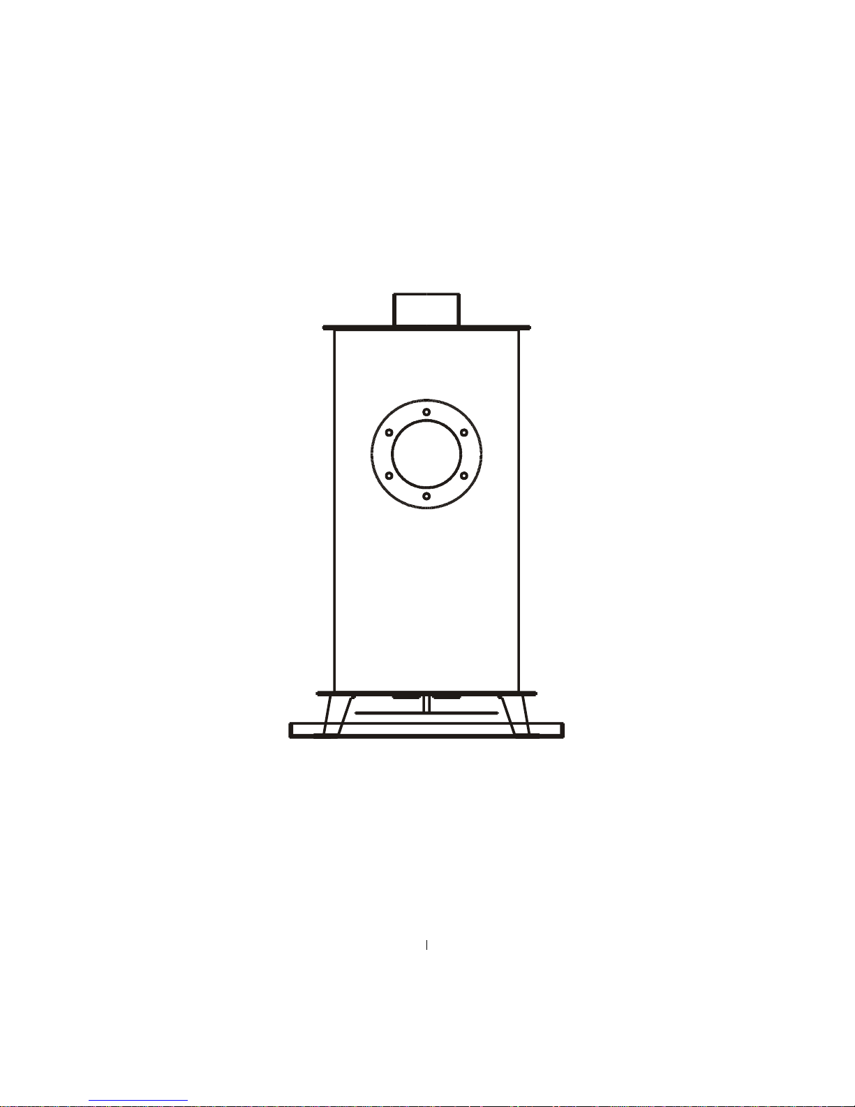
USER INSTRUCTIONS ISSUE 3
ROUND BUBBLE OIL STOVE ©
12-07-06
©
WWW.OILSTOVES.CO.UK
Page 2

INDEX
These instructions must be read in conjunction with-:
1. The appropriate oil valve document supplied with the
stove.
Valves fitted to this stove will normally be-:
The 252 AY ships valve made by O.C.I.
Or
The DVD valve made by Toby.
The Toby valve will normally be fitted to stoves with boilers as
it has the aqua-stat facility as an additional add on item, which
fastens on top of the valve.
2. The Installer document supplied with the stove.
3. DO NOT OPPERATE THE STOVE UNLESS YOU
HAVE READ THIS DOCUMENT AND FULLY
UNDERSTAND HOW IT WORKS AND
OPERATE IT SAFELY.
11--00 IINNTTRROODDUUCCTTIIOONN
1-0-1 WARNINGS
1-0-2 GENERAL INFORMATION
1-0-3 SPACING FROM COMBUSTIBLES
22--00 OOUUTTLLIINNEE OOFF CCHHIIMMNNEEYY PPRROOBBLLEEMMSS
33--00 OOUUTTLLIINNEE OOFF FFUUEELL SSUUPPPPLLYY PPRROOBBLLEEMMSS
3-0-1 COLD WEATHER WAXING.
3-0-2 TRIM.
3-0-3 POOR OIL FLOW PROBLEMS.
3-0-4 OIL FEED SET UP.
3-0-5 OIL LINE
44--00 HHOOWW TTHHEE SSTTOOVVEE WWOORRKKSS
4-9 THE COAL KIT
4-10 THE DESCALING DEVICE
4-11. STOVE COMPONENTS
55--00 RRUUNNNNIINNGG TTHHEE SSTTOOVVEE
5-1 OIL VALVE DETAILS
5-2 LIGHTING
5-3 WATER HEATING
66--00 FFAAUULLTT FFIINNDDIINNGG
77--00 RROOUUTTIINNEE MMAAIINNTTEENNAANNCCEE
88--00 WWAARRRRAANNTTYY
Phone 01302 742520
Fax 01302 750573
HOW TO
Further information. www.oilstoves.co.uk
11--00 IINNTTRROODDUUCCTTIIOONN
A great deal of effort has gone into the development of this
stove and it has been specifically designed for the narrow boat
user.
The Round Bubble stove has been designed to fit into confined
spaces and constructed in such a way as to make it possible to
strip down and repair any damaged part.
3.The circular shape allows the stove to be fitted with minimal
use of space, allowing easy access past it.
4.The stove can be supplied with a profiled drip tray.
5. The top of the stove can be used for warming and cooking.
7. Lightweight stainless steel or standard deck flanges and
traditional chimney extensions can used providing a suitable
antidowndraught terminal is fitted and providing that the
required flue vacuum readings can be achieved.
8. The dry stove will provide space heating via convection
together with limited cooking facilities on the top plate.
8a. The boiler version will provide the same with the addition
of hot water and central heating.
10. The stove incorporates a combustion air restrictor (C.A.R.)
as opposed to the more traditional swinging barometric damper
and also features easy access to the oil control valve.
1-0-1. WARNINGS
1. Never try to relight a hot stove; wait until it has cooled
down, hot oil vapour is explosive.
2. Never try to light a flooded pot, when attempting to light a
stove make sure that the pot is not flooded with oil, by looking
into the base of the burner.
If it is flooded remove the excess oil as per instructions in 6-9
of the faultfinding section.
3. If the stove or boat is left unattended, make sure that the
stove is turned off and the oil is turned off at the isolation valve
fitted prior to the oil entering the stove.
4. Make sure that fuel oil filters serving the stove are renewed
regularly in line with service requirements.
1-0-2. GENERAL INFORMATION ABOUT THE STOVE.
1. The stove is a space heater, which burns diesel oil in a
controlled manner utilizing a chimney to discharge the products
of combustion.
1-0-3. SPACING FROM COMBUSTIBLES.
1. The stove is designed to fit into a suitable fireplace.
2. The fireplace must be manufactured from fireproof materials.
3. For spacing from combustible materials the stove must be
treated in the same way as a SOLID FUEL APPLIANCE and as
such, whilst it is running, will become very hot and must not be
touched.
4. To prevent the risk of injury through burning a suitable
fireguard must be fitted and adequate provision made for
1
Page 3

guarding the exposed flue pipe where a potential danger is
presented.
5. The stove must not be operated with the mica-viewing panel
cracked or damaged.
6. The mica-viewing panel may require light cleaning
occasionally depending upon the continuous running time of
the stove.
7. The stove must be securely fastened down so that it can resist
impact or collision and it must be level in both directions.
22--00 OOUUTTLLIINNEE OOFF CCHHIIMMNNEEYY PPRROOBBLLEEMMSS
1. The fitting of any appliance, solid fuel, wood or oil burning,
requiring a naturally generated chimney vacuum, into a
traditional narrow boat creates specific problems, which are
mainly concerned with flues amongst other things.
2. Normally when fitting stoves into houses or bungalows
although there are many problems, generally if the chimney
comes out of the highest point of the property (normally the
ridge of the highest roof) stoves will work well in most normal
cases.
3. With boats the two major problems are -:
They move
And
By the nature of their shape, must have relatively low
chimneys.
4. Whilst on the move the boat will travel through a variety of
changing countryside which will have a dramatic effect on the
atmospherics at the chimney terminal.
5. An example of this would be the transition of a boat down
through a lock where the wind conditions at the outlet of the
chimney will change dramatically as the boat descends into the
lock to the lower water levels, severe down draught could
occur.
6. Great care must be followed with chimneys on boats and it is
critical to observe the following instructions.
7. To ensure satisfactory performance from the BUBBLE stove
chimneys must be capable of maintaining a constant steady
vacuum of not less than .04" Water Gauge when running on the
high fire position and not less than .02" Water gauge when
running on the low fire position
terminal conditions.
8. This obviously means that it is essential to fit a suitable anti
down draft device to the terminal of the chimney.
10. The chimney vacuum is directly proportional to the
following factors -:
10-1. The height of the chimney.
10-2. The resistance of the chimney. (Bends. terminals. etc.)
10-3. The cross sectional area of the chimney (diameter)
10-4. The Flue gas temperature.
10-5. The availability of replenishment air (ventilation)
10-6. The integrity of the chimney (does it leak)
11. The contents of the chimney are equal to a cylinder of hot
; at all times and in all
air which depending upon its temperature and volume wants to
move vertically, with some force.
12. Stopping it moving vertically are resistance such as-:
12-1. Smoothness of internal wall of chimney.
12-2. Chimney bends.
12-3. Chimney terminals.
12-4. Lack of ventilation. (Air going out must be replaced by
air coming in).
12-5. Atmospheric conditions at the chimney terminal that
could be affected by where the boat is moored.
IN SHORT -:
13-1 Hot air in large volumes = plenty of chimney pull.
(Vacuum)
13-2 Cold air in small volumes = little chimney pull.
13-3 Bends and chimney terminals create resistance to hot air
flow thus reducing potential maximum chimney vacuum.
14. Because it is not possible to use high chimneys it is critical
to observe the following instructions.
14-1. The chimney system must be designed so as to be easily
extendible.
14-2. The chimney can have a minimum inside diameter of
90mm.
14-3. Outside the boat, the chimney should be twin wall and
insulated to keep the flue gasses as hot as possible.
14-4. The chimney and stove must be adequately guarded to
prevent the risk of injury through burning.
15. When moored extend the chimney if you want the appliance
to be run at its maximum output, if you are happy with the
output of the stove running at up to setting 3, then it will not be
necessary to add the chimney extension.
16. The chimney terminal must be fitted with a terminal that
will resist down draughting in all terminal conditions.
16-1 MINIMUM HEIGHT FOR HIGH FIRE RUNNING IS 2.2
METER’S (long extension)
17. When cruising reduce the chimney height and turn the stove
down to match the reduced chimney height.
18. Do not cruise with the stove turned up on full output.
19. MINIMUM HEIGHT FOR LOW FIRE RUNNING IS 1.8
METERS. (Short extension)
20. When mooring pay particular attention to the
surroundings and remember that close objects such as high
buildings, trees or adjacent walls may well cause down or
up draughting.
Typical flue set ups can be seen in the illustrations FLUE
LAYOUT showing the flue pipe fitting into a standard cast iron
deck flange topped of with a traditional twin wall chimney,
terminating with a rotating cowl.
2
Page 4

33--00 FFUUEELL SSUUPPPPLLYY PPRROOBBLLEEMMSS
There are several problems relating to fuel supply of which you
need be informed.
WAXING - TRIM - ROLL
3-0-1. WAXING
1 Diesel has a nasty habit of waxing up when the temperature
gets down to or lower than freezing,
This waxing or thickening alters its flow characteristics and
consequently what was an adequate fuel feed supply can rapidly
turn into an inadequate one when the temperature starts to fall.
2 The worst scenario is fuel feed pipe 50-60 feet long in 8mm
dia pipe.
3 The best-case scenario is a fuel pipe 4 feet long in 15mm dia
with good insulated lagging.
3-0-2. (TRIM)
CHANGING OIL PRESSURE AVAILABLE AT THE
STOVE.
1. Because of the layout of a boat it is not possible to provide a
high pressure oil supply, in most cases a pressure head of out
18" is all that is available and as the tank empties this head of
pressure will reduce, and may alter the flow characteristics of
the fuel.
2. In some cases this head can also be affected by the ballast or
trim of the boat, the changing level of the boat due to addition
removal of ballast, fuel or water can have an effect on the
position of the oil tank in relation to the stove and the angle at
which the oil line is established.
3. Take great care to monitor all the effects of the different
ballast and trim possibilities.
4.Make sure that adequate oil feed is always available at the
outlet end of the fuel pipe before it enters the oil control valve
at the stove.
5. THE BOAT MUST NOT BE EXPOSED TO TRIM
ANGLES IN EXCESS OF 0.75 DEGREE’S.
3-0-3 POOR OIL FLOW PROBLEMS.
1. Bubble stoves have a very accurate oil flow control valve,
which is set up to give a precise oil flow at high and low fire.
3. For example the stove is flow rated at 3cc per minute on low
fire and 6cc per minute on high fire.
a. The test flow through the supply pipe should be well in
excess of the maximum flow rate of 6cc’s even when the
temperature is below freezing and the boat is adversely
trimmed.
3-0-4. OIL FEED SET UP
1. If the stove is fitted forward at the bow end of the boat, to
keep the oil feed supply as short as possible, a forward mounted
oil tank is recommended.
3. The tank should have insulating material around it for
protection from the effects of cold weather.
4. Always add a suitable proprietary antifreeze additive to the
stove fuel for wintertime running.
5. The tank should have conveniently sized filler and it must be
vented.
6. The tank should have-:
6-2. An isolation valve before an easily replaceable cartridge
filter and another isolation device close to the appliance to
allow for easy servicing.
3-0-5 OIL LINE
1. The oil feed line starts after the fuel filter and proceeds
to the point of entry, where the oil line goes into the
cab of the boat, at this point there will be a remote
sensing fire valve which is designed to shut off the oil
supply should a fire occur near to the stove.
2. The sensor for this valve should be fitted at roof level
in the space where the appliance is fitted.
There is a second valve provided with the stove, which is, pre
fitted at the oil entry to the oil control valve.
This one is designed to shut the oil supply off should the flame
be blown out and is known as a (Flame failure device) ffd.
Both valves have reset reset buttons, which allow you to recock them should they trip off.
If the stove is fitted with a Teddington KBB valve, press the
little black button to re cock the valve.
ISOLATION VALVE
5. If the bubble stove is fitted up to the first bulkhead the
isolation valve may well be fitted outside the cabin or saloon of
the boat and you should make sure that you know where it is
and how to operate it.
6. Because of the high risk of fuel contamination with water, we
strongly recommend the fitting of a high volume water trap in
the oil supply line. We have had to attend breakdowns on
several occasions where the diesel tank has had 50% water
contamination.
7. If there is a water trap fitted, make sure that you are fully
familiar with its operation and service requirements.
8. In case of emergencies, a suitable and serviceable fire
extinguisher should always be readily accessible near to the
appliance.
44--00 HHOOWW IITT WWOORRKKSS
1. The stove generates heat from burning oil mixed with air in a
vaporizing pot located in the bottom of the stove.
3. Once the stove is ignited, oil goes into the pot at a steady and
controlled rate via gravity flow, metered by the OIL
CONTROL VALVE the oil flow can be controlled from
minimum to maximum or any setting in between determined by
where you set the oil flow control knob.
Note. Stoves with boilers fitted will have an extra automatic
control for the water temperature. See the booklet provided
with the stove for more info on how this operates.
4. Air is sucked into the pot by the natural action of the
negative pressure in the chimney and to allow the chimney to
3
Page 5

work correctly it is essential that you have adequate,
unrestricted ventilation into the area where the stove is situated.
5. The amount of oil that can be successfully burned is directly
proportional to the amount of air that the chimney can draw into
the pot and so to achieve adequate combustion a balanced and
appropriate flow of both oil and air is required.
6. As stated earlier, the air side of the equation can vary wildly
with the changing performance of the chimney and so to
compensate for this the appliance has a built in combustion air
restrictor designed to maintain a steady and constant supply of
combustion air to the burner.
7. The flow of oil into the pot can be adjusted via the knob on
top of extension rod rising up from the oil control valve.
8. With the increased flow of oil, extra heat is generated, which
in turn stimulates the chimney to work harder and consequently
draw more air into the pot to maintain an adequate fuel air ratio.
4- 10. DESCALLING CONTROL
NOTE WELL
The descaling lever must not be touched whilst the stove is
running; it gets very hot and if touched, will cause severe
burning.
10-1. The descaling lever is a bent metal rod sticking out from
the lower right hand side of the appliance. It is used for
descaling carbon build up from the inside of the oil inlet
connection.
10-4. When the appliance is cold, rotate the lever occasionally
to remove any carbon build up at the point of oil entry into the
pot.
10-5. Every 6 months the descaling device will need to be
adjusted to stop oil leaks, on new stoves it may need adjusting
after the first two weeks of running.
To adjust the descaling device it is necessary to remove the
cover plate held in place with 4 self-tapping screws.
Remove the plate.
Tighten the nut up until a slight resistance can be felt as the
descaling lever is rotated,
Replace the cover plate.
4-11 STOVE COMPONENTS
The stove has the following components, which can be
removed for cleaning or servicing.
1. Removable hot plate
This is removed when the appliance is cold by inserting the
special lifting tool in to the hole in the centre of the plate and
lifting it off.
2. Removable baffle plate
With the hot plate removed it is then possible to lift out the
baffle plate.
When replacing the baffle plate make sure that the two screws
locate into the two holes on the baffle support plate.
3. Catalyser body
With the baffle plate removed it will be possible to lift out the
catalyser complete with the flame ring.
4. Circular Flame ring
5. Baffle support plate
On dry stoves this plate can be removed for cleaning purposes
by undoing the two M6 fasteners screwed in from the underside
of the plate.
6. The lighting port plug.
The lighting port plug pushes into the side of the stove, it is
designed to be a tight fit to avoid air leaking into the burner,
sometimes this can cause the plug to stick in place and be
difficult to remove, if it does become difficult to remove use a
10mm spanner on the hexagon nut and turn it clockwise to free
the plug from it’s socket.
5-0 RUNNING THE STOVE
1. We use different valves on dry stoves as opposed to stoves
with boilers.
2. We supply the appropriate literature packed in each stove.
3. You must familiarise yourself with all aspects of control
detailed within the booklet.
5-1 Oil Control Valve Details
1. The output of the stove is regulated by the amount of oil
allowed to go into it and this function is controlled by the -:
OIL CONTROL VALVE (O.C.V.), which is situated at the rear
of the stove.
On dry stoves the oil flow is controlled by turning the main
operating knob anti clockwise from it’s off position through
numbers 0 to 6.
5-2 LIGHTING
Lighting the stove takes a little time and patience; the following
procedure should be adopted
Turn the oil on at full rate for about 40 seconds and then turn
the oil off.
This should allow sufficient oil in to the bottom of the pot and if
you want to remove the inners of the stove to check you should
see a pool of oil about the size of a digestive biscuit.
DO NOT ALLOW ANY DEPTH OF OIL TO BUILD UP.
Remove the lighting port plug and impale a small piece of
firelighter on to the steel spike (about 10mm cube).
Light the firelighter and drop it into the bottom of the pot
down the lighting port tube and poke it into the oil pool.
8. If you have positioned the firelighter into the oil you will see
the flame start to grow and spread around the base of the pot,
this should take one to two minutes; at this stage turn the oil
flow on to setting 1.
9. The flame should then slowly change from yellow into blue
flame combustion and settle down to a steady burn.
9a. It is important to watch the flame during and after the
lighting process and if it starts to grow and become yellow turn
the oil off immediately and wait until the flame starts to die
down, when the flame starts to die down turn the oil control on
4
Page 6

to setting 1 and the burner should then settle down into blue
flame combustion.
9b. If it dies down into the bottom of the pot and goes yellow
this is a sign that there is insufficient oil coming into the pot.
Note there may be the occasional growl or audible vibration
whilst the burner settles down into blue flame combustion.
Do not turn the oil control knob up by any more than one
increment.
Allow 2 minutes for the burner to stabilize at each adjustment.
Make sure that you keep your eye on the stove for the first
half hour after it has first been ignited.
5-3 STOVES WITH BOILERS
1. Stove with hot water boilers are run in exactly the same way
as stoves without but there are extra controls detailed in the
booklet supplied with the stove.
66--00 FFAAUULLTT FFIINNDDIINNGG
6-1. RACING
1. Audible vibrations generated by the flame caused allowing
by too much oil in the pot, too quickly.
1-1. Turn off the oil flow until the burner has settled down to a
steady burn rate and then turn the fuel on again but don’t let the
flame go out otherwise the burner MUST be allowed to cool
down fully before a re-ignition is attempted.
6-2. FLUE VACUUM
1. The pot type burner is extremely sensitive to flue vacuum
variations.
2. Good combustion will not be possible unless our instructions
on chimneys and flue vacuum are followed.
3. If the burner does not burn with a blue flame, recheck the
chimney vacuum and oil flow rate.
4. If the burner does not run well check that the seals in the
stove are good and that there is no ingress of air into the
appliance flue ways.
6. Check that the correct fuel oil is being used.
7. Check the levels.
6-3. BURNER RUNS SOOTY.
Comments made on this subject assume that the appliance has
been running normally for some time.
1. If the stove soot’s up this indicates that there is not adequate
air for blue flame combustion or there is an excess of fuel.
1-1. Check that the chimney is working correctly. (This means
pulling enough air into the burner to allow correct blue flame
combustion to occur.
1-2. Check that the fuel is the correct type and quality.
1-3. Check that the flow rates are correct.
2. Where burners are incorrectly installed and are allowed to
run at high fuel flow rates on low chimney vacuums, long
unsatisfactory yellow flame combustion and bad sooting will
occur.
2-1. To rectify this problem call your service engineer.
3. Never switch from low settings straight up to high settings, a
longer burner life will be achieved if the oil flow control knob
is moved only by one number at a time leaving approx. two
minutes between each setting change.
6-4. BURNER DOES NOT LIGHT EASILY
Read the instructions in the lighting section of this publication.
6-5. OIL WILL NOT ENTER THE POT
All stoves
1. Is there oil in the fuel tank?
2. Has the fire valve or valves tripped.
3. Has the isolation valve been accidentally turned off?
4. Is the oil turned on at the oil flow control knob on the valve?
6. Is the oil feed pipe from the valve to the pot blocked.
(Unlikely)
(STOVES WITH BOILERS)
7. Has the oil trip lever tripped off?
8. Has the boiler stat tripped off?
6-7. OPERATING OIL FLOW RATES
OIL Flow rates in cc per minute.
min max
3cc 9cc
Oil Flow Rates In litres Per hour.
.18 litres .54 litres
Oil Flow Rates In litres Per 24 hours.
4.32 litres 12.96 litre
Oil Flow Rates In litres Per 7 x 24 hours.
30.24 litres 90.72 litres
To achieve optimum burner performance at these flow rates you
will need to have matching flue vacuums as stated in section 2.
6-8. OIL SMELLS
Visual check on all joints for obvious leaks.
Oil smells can be traced better when the stove is out.
The main cause of oil smell is lack of adjustment and service to
the descaling device.
Check that the descaling lever packing gland nut is adjusted.
6-9. DE-FLOODING A FLOODED POT.
If the stove is blown out by severe downdraughting, oil will run
into the pot to a depth of approx 15mm and then stop. If this has
occurred do not attempt to light the pot until it has been de
flooded.
To carry out this procedure you will need -:
a. A small leak proof plastic bag.
b. A small sponge.
c. A larger plastic bag for disposal of the residue.
5
Page 7

d. A pair of disposable plastic gloves.
Put a small plastic bag into the stove and sponge from the pot
into the bag, when the excess oil has been removed put the
plastic bag and sponge into another plastic bag and dispose of
it.
6-10. OIL LEAKS
If the stove has blown out, flooded oil should not leak from the
pot, if it has leaked into the drip tray it will have come from the
descaling seal or the boat could have been subject to heavy
movement causing the oil to splash around and leak through the
air holes in the side of the pot.
77--00.. RROOUUTTIINNEE MMAAIINNTTEENNAANNCCEE
ALL CARRIED OUT WITH STOVE COLD.
1. Every 7 days-:
Operate the descaling lever by turning it completely two or
three times.
3. Every 7 to 10 days -:
Clean the burner base by removing all the inner components as
follows,
1. Remove the hot plate
2. Remove the baffle plate
3. Remove the inner mesh catalyser and flame ring.
3. Scrape the bottom of the pot until it is clean, you will
notice a small carbon tide mark from the oil inlet to
the centre of the stove gently scrape this clean and vac
out.
4. Dust any soot or carbon build up from the catalyser or
flame ring.
Reassemble in the reverse order.
4. Every 24 weeks-:
Tighten up the gland nut on the descaling device to stop oil
smells.
5. Once per year-:
Have your service man replace or clean all the filters in the oil
supply line.
6. Every two years -:
Have your service man clean out the filter and check the
function of all the safety equipment associated with the stove,
oil supply and plumbing system.
Remove and clean out the oil supply pipe from the valve to the
pot.
7.As required -:
7a. Replace the Mica viewing panel.
7b. Replace the descaling device packing gland.
It is recommended that one of each mentioned in 7a and 7b be
carried as spares.
WWAARRRRAANNTTYY
The warranty covers all parts, with exception of the
components detailed below, for a twelve-month period,
from the date of purchase.
The warranty does not cover parts damaged by improper
use or improper installation.
1. Fill in the warranty form and returned it to us, the
information recorded on the warranty form helps us to deal
with any problems you may encounter.
2. Where we do not hold returned warranty forms
replacement parts would only be issued when we are sure
that the appliance has not been damaged by improper use
or installation.
3. The warranty covers PARTS ONLY for a period of ONE
YEAR and is conditional upon all the requirements of our
installation instructions being fully adhered to.
4. LABOUR, TRAVELING OR CONSEQUENTIAL LOSS
OR DAMAGE IS NOT COVERED.
Travelling and labour costs will be charged out on all
Warranty claims where service personnel are required for
on site visits.
4-1 Glass or Mica viewing panels are not covered under the
warranty.
5. ARRANGE FOR SERVICE visits with a service engineer.
COPYRIGHT HARWORTH HEATING LTD 14-11-02
This publication must not be copied by any means, without
written permission from the authors.
This product is subject to continuous development and
improvement and it is consequently acknowledged that due
to this process there may be some omissions, errors and
changes.
6
 Loading...