

Page 1
5
S
S
N
PPRREESSSSUURREE JJEETT CCOONNVVEERRSSIIOONN
R
AAYYBBUURRNN
R
S
UUPPRREEMME
S
E
N
OOUUVVEELLLLE
//N
E
//33555
IINNSSTTAALLLLAATTIIOONN IINNFFOORRMMAATTIIOON
http://www.oilstoves.co.uk/
Page 2

2
Contents
1. Health and Safety. ___________________________________________________________7
Control of Substances. ____________________________________________ 7
2. Applicable Regulations.
_______________________________________________________7
Building Regulations._____________________________________________ 7
Electrical Regulation.
_____________________________________________ 7
BS5410 Oil Fired Space Heaters. _____________________________________ 7
BS5449 Central Heating. __________________________________________ 7
BS6461 Pts 1 & 2 1984. ___________________________________________ 7
BS7566 Parts 1 to 4. _____________________________________________ 7
OFTEC Regulations. _____________________________________________ 7
3. Introduction._______________________________________________________________7
4. Check List. ________________________________________________________________8
1. How is the Appliance Used.
_______________________________________ 8
2. Chimney.___________________________________________________ 8
3. Existing Heat Load. ____________________________________________ 8
4. Overloading._________________________________________________ 9
5. Under Loading. _______________________________________________ 9
6. Hot water (Primary Pipe work). _____________________________________ 9
7. Oil Supply Line And Tank Location. _________________________________ 9
8. Electrical Requirements.
_________________________________________ 9
9. Ventilation Requirements. ________________________________________ 9
5. How It Works.
____________________________________________________________10
1. Maximum Allowable Heat Load. ___________________________________ 10
2. Typical Run Sequence.
3. Heat Balancing the Conversion.
_________________________________________ 10
____________________________________ 10
4. The Heat Load. ______________________________________________ 10
5. The nozzle size.______________________________________________ 10
6. The pump pressure. ___________________________________________ 10
7. Oven Side Casting.____________________________________________ 10
8. The baffle system. ____________________________________________ 10
6. Materials Required. _________________________________________________________11
1. Suitable chimney liner. _________________________________________ 11
2. Suitable anti down draft terminal. __________________________________ 11
4. Vit to copex adapter.___________________________________________ 11
6. Oil isolation valve. ____________________________________________ 11
7. Remote sensing fire valve
_______________________________________ 11
8. 10mm kutalex copper tube._______________________________________ 11
Page 3

3
9. Wall sleeving 22mm waste pipe. ___________________________________ 11
10. Silicone sealant. _____________________________________________ 11
11. Stadium air vent. ____________________________________________ 11
12. Vermiculite loose fill. (optional)
13. Cement.
__________________________________________________ 11
__________________________________ 11
14. Sharp sand. ________________________________________________ 11
15. Fire cement. _______________________________________________ 11
16. Plugs and screws. ____________________________________________ 11
17. Compression fittings. _________________________________________ 11
18. 29 and 16mm hole saws. _______________________________________ 11
19. Disk cutter blades.
20. 6 kg tub firecement.
___________________________________________ 11
__________________________________________ 11
21. Silicone sealant. _____________________________________________ 11
22. Small tin heat resistant paint._____________________________________ 11
23. 10 mm pipe clips. ____________________________________________ 11
24. Protective clothing (gloves,masks etc). ______________________________ 11
25. WD 40. __________________________________________________ 11
26. Small Tube 2 part epoxy. _______________________________________ 11
7. Chimney and Flue Vacuum. ___________________________________________________11
1. Down Draught. ______________________________________________ 11
2. Up Draughts. _______________________________________________ 11
3. Fume leaks. ________________________________________________ 11
3a. Regular blockages.
4. Exposed Chimneys.
___________________________________________ 11
___________________________________________ 11
5. Terminal Positions. ___________________________________________ 12
7. Cleaning Access. _____________________________________________ 12
8. Flue pipe Diameter and Specs. ____________________________________ 12
9. Bends In Flues And Chimneys. ____________________________________ 12
10. Warning. _________________________________________________ 12
11. Chimney Vacuum. ___________________________________________ 12
8. Oil Feed and Storage. ________________________________________________________13
1. Fuel Types. ________________________________________________ 13
2. Fuel Supply Pipe Work._________________________________________ 13
3. Protection of the Environment. ____________________________________ 13
4. Underground Oil Supply Pipes.
5. Fuel Oil Storage Tanks.
_________________________________________ 13
____________________________________ 13
6. Fuel Tank Size. ______________________________________________ 13
7. Environmental Protection Oil Spillage. _______________________________ 13
8. Fuel Filter. _________________________________________________ 14
9. Fire and IsolationValves. ________________________________________ 14
Page 4

4
9. Connection to the Burner. _______________________________________ 14
9. Ventilation Requirements._____________________________________________________14
1. Air Supply To The Appliance._____________________________________ 14
2. Air Requirement Calcs. _________________________________________ 14
3. Effects of Extractor Fans.________________________________________ 15
4. Effects of Open Fires. __________________________________________ 15
5. Test for Adequacy of air supply. ___________________________________ 15
6. WARNING.
10. Existing Heating System. _____________________________________________________15
________________________________________________ 15
1. Compliance with British Standards. _________________________________ 15
2. Primary System. _____________________________________________ 16
11. Electrical Requirements. _____________________________________________________ 16
1. Earthing. __________________________________________________ 16
2. Controls. __________________________________________________ 16
3. Fusing. ___________________________________________________ 16
12. Main Steps Installation. _____________________________________________________16
1. Check out the Existing Heating System . ______________________________ 16
2. Clean Chimney.______________________________________________ 16
3. Line the Chimney if Required. ____________________________________ 16
4. Check and Adjust Flue Vacuum.
5. Provide a Cleaning Access.
___________________________________ 16
______________________________________ 16
6. Install Fuel Tank._____________________________________________ 16
7. Run a Fuel Line. _____________________________________________ 16
8. Modify the Electrical Supply if Req’d. _______________________________ 16
9. Fit Suitable Time Control System. __________________________________ 16
10. Fit Suitable Ventilation. ________________________________________ 16
APPLIANCE _________________________________________________ 17
12. Remove The Hot Plate.
13. Remove The Clinker Clean Out Door.
________________________________________ 17
_______________________________ 17
14. Remove The Firebars. _________________________________________ 17
15. Remove The Rear Bar Carrier.____________________________________ 17
16. Unscrew The Chrome Riddling Lever._______________________________ 17
17. Remove The L.H Side Panel Access Cover. ___________________________ 17
18. Remove The Ashpit Door. ______________________________________ 17
19. Warning re Air for Combustion.___________________________________ 17
20. Remove The Ash pan .
________________________________________ 17
21. Remove The Flexi Stat Drive. ____________________________________ 17
22. Clean the door. _____________________________________________ 17
23. Remove The Front Fire Brick Beneath The Fuel Loading Door. _______________ 17
Page 5

5
24. Remove The Front Secondary Air Chamber Casting.______________________ 17
25. Remove The Vitreous Enamel Cover Plate.____________________________ 18
25a.Fit The Over Boiler Baffle. _____________________________________ 18
27. Clean the Boiler and Flueways.
28. Remove The Sliding Damper.
___________________________________ 18
____________________________________ 18
29. Fit The Over Oven Baffle. ______________________________________ 18
30. Using The Hole Saws. _________________________________________ 19
12a. Boards And Closure Plate. ___________________________________________________19
1. Fit The Two Oven Side Fireboards. _________________________________ 19
2. Fit The Closure Plate. __________________________________________ 20
3. Fit The Ash Pit R.H. Side Insulating Board. ____________________________ 20
5. Fit The Base Closure Plate Board. __________________________________ 21
6. Fit The Primary Front Board. _____________________________________ 21
9. Fit The Secondary Closure Plate Board._______________________________ 22
10. Permanently Firecement. _______________________________________ 22
11. Fit the Burner.
12. Plug in the Three Pin Plug.
12b. Services Into The Burner. ___________________________________________________22
______________________________________________ 22
______________________________________ 22
1. Oil Feed. __________________________________________________ 22
2. Oil Isolation Valve.
___________________________________________ 22
3. Oil Pipework To Pressure Jet Burners. _______________________________ 22
4. Power In. __________________________________________________ 23
12c. About The Thermostat. _____________________________________________________23
1. Fit The New Phial.
____________________________________________ 23
2. Refit The Access Panel._________________________________________ 24
3. Line The Chimney. ___________________________________________ 24
4. Fit Ventilation. ______________________________________________ 24
5. Connect The Chimney. _________________________________________ 24
6. Connect The Electrical Supply. ____________________________________ 24
7. Backfill Around The Liner _______________________________________ 24
8. Fit Anti Down Draught Cowl
_____________________________________ 24
13. Commissioning. ___________________________________________________________24
1. Setting the Burner Up.__________________________________________ 24
2. Heat Balancing the System. ______________________________________ 24
3. Lighting. __________________________________________________ 24
3.1. To Bleed The Pump.
3.2. Set The Control Stat. _________________________________________ 24
3.3. Set The Time Clock. _________________________________________ 24
3.4. Check The Burner Air Shutter. ___________________________________ 25
_________________________________________ 24
Page 6

6
3.5. Prepare A Sampling Point. ______________________________________ 25
3.6. Ignite The Burner. ___________________________________________ 25
3.7. Fit The Baffle Box. __________________________________________ 25
3.8. Fit the Hot Plate.
3.9. To Set For Good Combustion.
____________________________________________ 26
___________________________________ 26
3.10. Combustion Air. ___________________________________________ 26
3.11. To Adjust The Pump Pressure. __________________________________ 26
4. Final Checks. _______________________________________________ 27
4.1. Fuel Tank. ________________________________________________ 27
4.2. Fuel. ___________________________________________________ 27
4.3. Filter.
4.4. Site Glass or Tank Gauge.
___________________________________________________ 27
______________________________________ 27
4.5. Oil line. _________________________________________________ 27
4.6. Fire valves. _______________________________________________ 27
4.7. Through Wall Sleeving. _______________________________________ 27
4.8. Isolation valve. _____________________________________________ 27
4.9. Electrical. ________________________________________________ 27
4.10. Ventilation. ______________________________________________ 27
4.11. Chimney System.___________________________________________ 27
4.12. Check controls Function.
______________________________________ 27
4.13. Instruct User. _____________________________________________ 27
4.14. Vent the Ashpan Door. _______________________________________ 27
14. Warranty . ______________________________________________________________28
Items Not Covered Under the Warranty
________________________________ 28
Labour. ____________________________________________________ 28
Travelling time. _______________________________________________ 28
Consequential loss or damage. ______________________________________ 28
Nozzles. ____________________________________________________ 28
Baffle kits and Insulation Boards. ____________________________________ 28
Damage to the Fuel Pump. ________________________________________ 28
15. Fault Finding. ____________________________________________________________28
16. Servicing. _______________________________________________________________29
18. Figures. ________________________________________________________________29
FIG 10 Boiler Stat
FIG 11 Sectional Details
______________________________________________ 29
__________________________________________ 25
Fig 12 Board Details ____________________________________________ 25
Fig 13 Grind Door______________________________________________ 26
Fig 14 Exploded Parts List ________________________________________ 26
Fig 15 Oven Stat Details __________________________________________ 27
Packing List _________________________________________________ 27
Page 7

7
H
EEAALLTTHH AANNDD
11.. H
C
C
OONNTTRROOLL OOFF
S
S
UUBBSSTTAANNCCEES
S
S
S
AAFFEETTY
..
Y
..
Take great care when handling
materials such as insulation boards,
glass fibre ropes, ceramic wool,
artificial fuel, kerosene and diesel oil,
they are all irritants and suitable
protective clothing such as disposable
gloves dust masks and protective
goggles should be worn.
Wash off thoroughly after handling
any of these materials.
Carefully dispose of redundant or
surplus materials and always vac up
after service or installation work.
A
22.. A
PPPPLLIICCAABBLLEE
R
EEGGUULLAATTIIOONNS
R
S
..
The installation of an oil fired
BUBBLE © appliance must be carried
out by a technically competent person,
experienced in both solid fuel and oil
fired installation and capable of
installing, commissioning and servicing
to the current requirements of the
relevant local building regulations.
B
B
UUIILLDDIINNGG
R
R
EEGGUULLAATTIIOONNS
S
..
Codes of practice which apply in the
UK are -:
BBSS55441100 O
IILL
F
IIRREEDD
S
PPAACCEE
H
H
EEAATTEERRS
S
..
O
F
S
Installation of oil fired space heating
and hot water supply Part 1, boilers of
rated output not exceeding 44kW
BBSS44554433 C
C
HHIIMMNNEEYY
S
S
PPEECCIIFFIICCAATTIIOONNS
S
.
.
Specification for chimney for oil fired
appliances. Part3.
BBSS55444499 C
C
EENNTTRRAALL
H
H
EEAATTIINNG
G
.
.
Central heating for domestic premises
Part 1 Forced circulation hot water
systems.
.
BBSS 55660011 BBSS88330033.
BBSS66446611 P
BBSS77556666 P
OOFFTTEECC R
P
TTSS
P
AARRTTSS
R
EEGGUULLAATTIIOONNS
11 && 22 11998844..
TTOO
S
44..
..
11
Installers must have successfully
completed OFTEC courses, OFT101
and OFT105.
Failure to comply with the relevant
requirements listed above can be
hazardous and could lead to
prosecution under the law.
In England and Wales these are J 1-23 Provision for introduction of air
supply and discharge of products of
combustion. Provision for protection
against fire and heat.
In Scotland Part F sec 3.
In Northern Ireland Part L. In
Ireland Part J.
E
E
LLEECCTTRRIICCAALL
R
R
EEGGUULLAATTIIOON
N
..
British IEEE wiring regulations, latest
edition.
If you have any difficulties please
phone our sales department on
PHONE 01302 742520. (3 lines.)
FAX 01302 750573
Email [email protected]
Web site www.oilstoves.co.uk
I
NNTTRROODDUUCCTTIIOON
33.. I
N
..
There are several of potential
problems that can affect the way a
converted appliance works.
Page 8

8
To protect yourself against
dissatisfied customers you must make
sure that you are fully aware of them.
The best way to deal with these
problems is to take-:
A check list
and
A user manual
Obviously it doesn,t and sometimes it
is necessary to just to make sure that
they do fully understand what a
conversion is all about.
For customers who do a lot of cooking,
go through the typical run scenario
with them and make sure that they
understand how the converted
appliance will work.
On your site visit and make sure you
cover all the points raised in the
check list and give the customer a
copy of the user manual.
The user manual is designed to help
customers understand more about
how a conversion will effect their
appliance and will also answer many of
the questions likely to be asked.
If you miss anything, it could result in
an unhappy customer and invariably
you will finish up footing what could
be a large bill.
Remember what works for a solid fuel
system does not always work for oil
fired conversion particularly on the
hot water side.
11.. H
H
OOWW IISS TTHHEE
A
A
PPPPLLIIAANNCCEE
U
D
SSEED
..
U
Do they do all the cooking on it?
What do they cook on in summer
time?
Do they use it mainly for central
heating?
What do they expect from a
converted appliance?
22.. C
C
HHIIMMNNEEY
Y
..
Do they have any down draught
problems?
Do they have excessive vacuum
problems?
Will The Chimney need relining?
33.. E
E
XXIISSTTIINNGG
H
H
EEAATT
L
L
OOAAD
D
..
C
44.. C
HHEECCKK
L
L
T
IISST
..
Make sure that customers know what
they are going to get for their money.
Some are under the misguided
impression that once the appliance has
been converted, it suddenly changes
into something entirely different,
with a whole host of features it never
had before.
Check out the existing system to see
if it under or overloaded or about
right.
For Gravity Circuits allow
8,000 BTU’s for Hot Water
38,000 BTU’s on Rads Max.
20% Pipe losses.
For Fully Pumped Circuits allow
8,000 BTU’s for Hot Water
Page 9

9
44,000 BTU’s on Rads Max.
20% Pipe losses.
44.. O
O
VVEERRLLOOAADDIINNG
G
..
If the appliance is overloaded and
trying to heat a system with a
combined heat load in excess of
55,000 BTU’s the burner will run for
long continuous periods without a
break, this will then result in
excessive oven temperatures and
excessive burner temperature.
This will result in overheating of the
fan motor and damage to the
bearings.
U
55.. U
NNDDEERR
L
L
OOAADDIINNG
G
..
If there are only a few radiators on
the system, this will cause the burner
to shut down quickly and then the
oven will not reach the desired
temperature.
The underloading problem can be
easier to deal with than the
overloaded situation, read the Heat
Balancing section for further info.
66.. H
H
OOTT WWAATTEERR
P
((P
RRIIMMAARRYY
P
P
IIPPEE WWOORRK
K
))..
Solid Fuel stoves should always
produce good quantities of hot water
because the fire runs continuously and
at high temperatures.
This is not the case with converted
appliances and it is therefore
important to make sure that the hot
water side of the system is adequate.
Because water temperature control is
not all it should be, many of the
cylinders have been exposed to
excessive and continuous high
temperature calcification in the
indirect coil.
This can result in major post
conversion heat exchange problems
and consequent lack of hot water.
If the primary pipe work does not
look adequate, modify it and fit a fully
pumped, three port valve system.
O
S
L
A
T
77.. O
IILL
S
UUPPPPLLYY
L
IINNEE
T
AANNKK
L
L
OOCCAATTIIOON
A
NNDD
N
..
Positive head systems are required.
Tiger loop systems will not work on
solenoid pump burners.
Lift pumps can be used.
12 Volt Fuel pumps can be used.
88.. E
E
LLEECCTTRRIICCAALL
R
R
EEQQUUIIRREEMMEENNTTS
S
..
Make sure that there is a 3 amp,
switch fused supply near to the
appliance.
If the customer wants a time clock
remember that you will have to
arrange for cabling to the burner and
the central heating pump.
V
99.. V
EENNTTIILLAATTIIOONN
R
R
EEQQUUIIRREEMMEENNTTS
S
..
Check on the existing ventilation, if it
is not adequate modify accordingly.
Take care with indirect systems which
have been running for a long time on
solid fuel systems.
Page 10

10
H
55.. H
M
11.. M
OOWW
AAXXIIMMUUMM
I
W
TT
I
W
A
LLLLOOWWAABBLLEE
A
S
OORRKKS
..
H
L
D
L
OOAAD
..
H
EEAATT
The conversion system is designed and
tested to operate at its best on total
system loads of between 35,000 and
55,000 B.T.U's, under winter time
conditions.
22.. T
T
YYPPIICCAALL
R
R
UUNN
S
S
EEQQUUEENNCCE
E
..
Upon starting from cold, the burner
should run for a maximum of 40 to 55
minutes before shutting down into its
modulating mode.
(The rate of modulation thereafter
will depend to some extent on the
system size and the use of appliance
controls.)
If conversions are carried out on
these systems, it is very important
that adequate explanation be made to
the customer.
Selected heating only is available,
meaning that selected radiators are
turned on and off as required, to keep
the total maximum system load within
our stated requirement of 55,000
BTU,s.
T
55.. T
HHEE NNOOZZZZLLEE SSIIZZE
E
..
Nozzles from .3 to .5 U.S. Gallons can
be used
T
HHEE PPUUMMPP PPRREESSSSUURRE
66.. T
E
..
The pump can be set to run from 7 to
10 Bar
After the 40 to 55 minutes the oven
should be coming up to 170 to 190 deg
C and the heating system should be
around 65 deg C.
This performance can be achieved on
both larger and smaller systems but it
will depend greatly upon compliance
with our recommendations and
requirements contained within these
instructions.
H
33.. H
B
EEAATT
B
AALLAANNCCIINNGG TTHHEE
C
C
OONNVVEERRSSIIOON
N
..
Great care will be required in setting
up the correct heat balance for each
appliance, here is a list of items which
may require adjustment to achieve
the correct set up
T
H
44.. T
HHEE
H
EEAATT
L
L
OOAAD
.
D
..
Many Supreme's and Nouvelle's are
installed on central heating systems,
which are much too large.
O
S
77.. O
VVEENN
S
IIDDEE
C
C
AASSTTIINNG
G
..
For oil-fired conversion, the oven side
casting is exposed to the heat from
the flame.
If the oven overheats additional
insulation boards can be cut and
fitted.
T
88.. T
HHEE BBAAFFFFLLEE SSYYSSTTEEM
M
..
The baffle system can be adjusted
from summer to wintertime running by
rotating it to the required position.
The baffle is fitted over the flame
tube as illustrated.
There are two rectangular cut outs in
the vertical sides of the baffle which
can be positioned to point to -:
1. The rear and left hand side for
intensive water heating or wintertime
running
Or
Page 11

11
2. The front and right hand side for
intensive cooking or summer time
running.
Or
3. To the right and rear for
intermediate running.
It can be set up to bias the flame to
the oven or the boiler or an
intermediate position.
T
99.. T
HHEE AAPPPPLLIIAANNCCEE CCOONNTTRROOLLS
S
.
.
Thermostat and chrome cook - heat
lever.
M
66.. M
11.. S
22.. S
44.. V
66.. O
AATTEERRIIAALLSS
S
UUIITTAABBLLEE CCHHIIMMNNEEYY LLIINNEER
S
UUIITTAABBLLEE AANNTTII DDOOWWNN DDRRAAFFTT TTEERRMMIINNAAL
V
IITT TTOO CCOOPPEEXX AADDAAPPTTEER
O
IILL IISSOOLLAATTIIOONN VVAALLVVE
R
EEQQUUIIRREED
R
R
..
E
..
D
..
R
..
L
..
D
1199.. D
IISSKK CCUUTTTTEERR BBLLAADDEES
2200.. 66
KKGG TTUUBB FFIIRREECCEEMMEENNT
S
2211.. S
IILLIICCOONNEE SSEEAALLAANNT
S
2222.. S
MMAALLLL TTIINN HHEEAATT RREESSIISSTTAANNTT PPAAIINNT
2233.. 1100
2244.. P
EETTC
2255.. WWDD 4400..
2266.. S
MMMM PPIIPPEE CCLLIIPPS
P
RROOTTEECCTTIIVVEE CCLLOOTTHHIINNGG
C
))..
S
T
T
UUBBEE
MMAALLLL
S
T
..
S
..
22
PPAARRTT EEPPOOXXY
..
T
..
(
(
GGLLOOVVEES
Y
..
S
,
,
MMAASSKKSS
T
..
C
HHIIMMNNEEYY AANNDD
77.. C
F
LLUUEE
F
V
AACCUUUUM
V
M
..
It is most important that any existing
chimney faults such as: -
D
11.. D
OOWWNN
D
D
RRAAUUGGHHT
T
..
Occasional or permanent down
draught (see illustrations)
R
EEMMOOTTEE SSEENNSSIINNGG FFIIRREE VVAALLVVE
77.. R
0
88.. 110
MMMM KKUUTTAALLEEXX CCOOPPPPEERR TTUUBBE
W
99.. W
AALLLL SSLLEEEEVVIINNGG
S
1100.. S
IILLIICCOONNEE SSEEAALLAANNT
S
1111.. S
TTAADDIIUUMM AAIIRR VVEENNT
V
1122.. V
EERRMMIICCUULLIITTEE LLOOOOSSEE FFIILLL
C
1133.. C
1144.. S
1155.. F
1166.. P
1177.. C
1188.. 2299
T
EEMMEENNT
S
HHAARRPP SSAANND
F
IIRREE CCEEMMEENNT
P
LLUUGGSS AANNDD SSCCRREEWWS
C
OOMMPPRREESSSSIIOONN FFIITTTTIINNGGS
AANNDD
222
..
D
..
T
..
6
116
MMMM HHOOLLEE SSAAWWS
E
E
..
2
MMMM WWAASSTTEE PPIIPPE
T
..
T
..
L
(
.. (
OOPPTTIIOONNAAL
S
..
S
..
S
..
U
22.. U
D
PP
D
RRAAUUGGHHTTS
S
..
Excessive up draughts
F
33.. F
E
..
UUMMEE LLEEAAKKS
3
A
R
3
A
.. R
EEGGUULLAARR BBLLOOCCKKAAGGEES
S
..
S
..
If there are regular blockages the
causes must be established and
corrected before any installation
L
))
work is carried out.
44.. E
E
XXPPOOSSEEDD
C
C
HHIIMMNNEEYYS
S
..
If the chimney is on an exposed wall,
always reline and backfill around the
lining with vermiculite to keep it warm
and prevent condensation.
Page 12

12
55.. T
T
EERRMMIINNAALL
P
P
OOSSIITTIIOONNS
S
..
The chimney should terminate 2 feet
above the ridge of the main or
highest roof, in compliance with
relevant legislation.
The chimney must be terminated with
a suitable anti down draft cowl such
as a VEDETTE or EUROCOWL ETC.
G
66.. WWAARRNNIINNG
.
On installations where using a bend is
unavoidable the maximum allowable
bend angle from the vertical is 45
degrees.
45-degree runs should be kept as
short as possible (less than 1 metre
long) and there should never be more
than two bends used.
W
1100.. W
AARRNNIINNG
G
..
Abnormal chimney terminal locations
are very likely to cause problems
under certain windy weather
conditions.
If you are unsure about the condition
of the chimney, have it thoroughly
cleaned and checked by a suitably
qualified person.
77.. C
C
LLEEAANNIINNGG
A
A
CCCCEESSS
S
..
Provision must be made to allow
adequate and easy access into the
chimney for cleaning purpose.
88.. F
F
LLUUEE PPIIPPEE
D
D
IIAAMMEETTEERR AANNDD
S
S
PPEECCS
S
..
The flue pipe from the stove must not
be less than 125mm diameter and
must comply to one of the following -:
Acid resistant vitreous enamelled flue
pipe to BS 1344 Part 2.
Stainless steel to BS1449 Part 2.
Cast iron to BS41.
Mild steel with a wall thickness of 2
mm minimum.
B
I
F
A
99.. B
EENNDDSS
I
NN
F
LLUUEESS
A
NNDD
C
C
HHIIMMNNEEYYS
S
..
Horizontal flue runs are not allowed.
1111.. C
C
HHIIMMNNEEYY
V
V
AACCUUUUM
M
..
A constant steady vacuum of not less
than .02" W.G. when COLD or more
than .05" W.G. when HOT is required.
To achieve this line chimneys as
follows-:
1. On chimneys above 25 - 30 feet use
5-inch dia linings
2. On chimneys less than 25 feet use
6-inch dia linings.
3. Chimney less than 20 feet may not
generate the required vacuum and in
these cases it may be necessary to fit
a chimney fan.
The flue vacuum can be adjusted by
use of a swinging barometric damper,
which should be fitted via a vitreous
tee piece into the flue pipe in the
same room as the appliance.
The counterweights on the swinging
dampers can be adjusted in or out to
give the required vacuum.
Flues and chimneys should always be
vertical wherever possible.
Page 13

13
O
88.. O
F
UUEELL
11.. F
IILL
T
T
F
F
YYPPEES
EEEEDD AANNDD
S
..
S
TTOORRAAGGE
S
E
..
28 Second Commercial Kerosene to
BS2869 Part 2: 1988 Class C2 is
suitable for use with this appliance.
35-second diesel versions are
available to special order.
F
S
P
W
K
22.. F
UUEELL
S
UUPPPPLLYY
P
IIPPEE
W
OORRK
..
Installation of all oil feed pipe work
and storage equipment should be in
line with -:
BS5410 Part1
The burner can be supplied with oil via
gravity or pumped oil feed system.
If a gravity system is used the base
of the tank must not be less than half
a metre or more than three metres
above the burner.
The minimum fuel line diameter is 10
mm but this is dependent upon the
length of run.
If other appliances are being supplied
from the same oil supply allowance
must be made when pipe sizing to
ensure that an adequate supply of oil
be maintained for each appliance.
The oil line must be sleeved and
sealed in a plastic tube where it
passes through any brickwork.
U
44.. U
NNDDEERRGGRROOUUNNDD
O
S
P
S
O
IILL
S
UUPPPPLLYY
P
IIPPEES
..
Trenches must be a minimum of
300mm deep.
Oil lines laid in such trenches should
have a substantial cover; strong
enough to resist spade impact placed
over them and marker tapes must be
used.
For further advice phone our
technical help line.
F
O
55.. F
UUEELL
O
IILL
S
S
TTOORRAAGGEE
T
T
AANNKKS
S
..
Steel oil storage tanks to BS799 Part
5, if there is any doubt about the
suitability of the fuel tank, consult
the tank manufacturer.
For further reference see OFTEC
requirements book T3 July 1995
rev.7.95
Where the tank will be fitted at a
lower level than the stove a lift pump
must be used with max head above
the burner base of 3 metres, the max
head of the lift pump over the oil
supply tank must not exceed 5
metres.
F
T
S
E
66.. F
UUEELL
T
AANNKK
S
IIZZE
..
Minimum size storage tank should be
300 gals.
E
77.. E
NNVVIIRROONNMMEENNTTAALL
S
S
PPIILLLLAAGGE
E
..
P
P
RROOTTEECCTTIIOONN
O
O
IILL
P
33.. P
RROOTTEECCTTIIOONN OOFF TTHHEE
E
E
NNVVIIRROONNMMEENNT
Environment protection is of
paramount importance, where oil lines
are to be buried, special care is
needed to ensure that they can’t be
damaged or cut through.
T
..
Environment protection is of
paramount importance.
Where properties are prone to be at
risk from flooding take great care
when fitting oil storage tanks.
Page 14

14
Make sure that they are supported on
reinforced concrete walls, which are
built high enough to keep the tank
well above any potential flood level
and strong enough to withstand
swollen river current or flood tide
conditions.
Make sure that the tank is firmly
fixed to the supporting walls so as not
to be washed away.
Tall, slim line plastic oil tanks must be
secured to a substantial base to
prevent them from being blown over
when they are empty or have low oil
content.
F
F
R
88.. F
UUEELL
F
IILLTTEER
..
A suitable filter / water trap must be
fitted with a 100-micron element.
C
99.. C
OONNNNEECCTTIIOONN TTOO TTHHEE
B
B
UURRNNEER
R
..
The burner is supplied with a flexible
oil line with a union fitting into the
pump, jointing compound must not be
used at the union connection and the
flexi pipe should be neatly laid so that
upon disconnection it can be moved to
the left hand side of the burner unit
to allow room for the modular burner
system to be easily withdrawn from
within its compartment.
V
EENNTTIILLAATTIIOONN
99.. V
A
IIRR
S
S
11.. A
UUPPPPLLYY
R
EEQQUUIIRREEMMEENNTTS
R
T
T
OO
T
HHEE
A
A
PPPPLLIIAANNCCE
T
E
..
S
..
If the appliance has been installed in
line with current regulation there
should already be an adequate air vent
for the appliance to function as a solid
fuel appliance
The minimum fuel line diameter is 8
mm but this is dependant upon its
length of run.
99.. F
F
IIRREE AANNDD
I
I
SSOOLLAATTIIOON
N
V
V
AALLVVEES
S
..
Two remote acting fire valves such as
a Teddington KBB should be fitted.
One (60 Deg C) mounted at high level
over the appliance and the other
fitted with the phial bulb mounted in
the base of the ash pan, at the front
of the appliance 90 deg C.
There must also be an isolation valve
fitted in the same room as the
appliance in a conveniently accessible
place.
See Building Regulations J1/2/3
section 4.and BS5410 part1.
A
22.. A
R
IIRR
R
EEQQUUIIRREEMMEENNTT
C
C
AALLCCS
S
..
Calculate air requirements at 5.5 cm
sq per kW of output.
It is most essential that a permanent
free air supply be established, as the
burner cannot function correctly
without it.
Provision for an adequate FREE air
supply in to the room and house where
the appliance is fitted is required and
can be established by multiplying the
kW oil input of the appliance by 5.5cm
sq.
This will take the form of a purpose
designed, NON hit or miss, air vent of
90 sq cm cross sectional area.
Page 15

15
33.. E
E
FFFFEECCTTSS OOFF
E
E
XXTTRRAACCTTOORR
F
S
F
AANNS
..
If an extractor fan is fitted in the
same room as the appliance or if
there is an open fire in an adjoining
room then extra compensatory air
must also be made available for both
these extra requirements.
Minimum extra requirement for
extractor fans is 55 sq cm and it is
preferred if the extra air supply can
be positioned in such a way as it can
supply air to the extractor fan
without the air stream passing the
stove.
44.. E
E
FFFFEECCTTSS OOFF
O
F
S
F
IIRREES
..
O
PPEENN
If there is an open fire in the same
room as the appliance then further
extra ventilation must be provided.
The minimum extra requirement for
open fires is 212 sq cm
55.. T
T
EESSTT FFOORR
A
DDEEQQUUAACCYY OOFF AAIIRR SSUUPPPPLLY
A
Y
..
Test for adequacy of air supply is to-:
Set the oil fired appliance going, close
all doors and windows in the room,
turn on the extractor fan to its
maximum capacity, light the open fire
and let it get well established,
Test for adequate maintenance of
chimney vacuum on the appliance, both
before and after the extractor fan is
turned on, with the open fire going.
66.. WWAARRNNIINNGG..
Instructions on ventilation must be
adhered to.
E
1100.. E
11.. C
XXIISSTTIINNGG
C
OOMMPPLLIIAANNCCEE WWIITTHH
H
EEAATTIINNGG
H
B
B
RRIITTIISSHH
S
S
S
S
TTAANNDDAARRDDS
M
YYSSTTEEM
S
..
..
Before you start remember that
because this is an existing solid fuel
central heating system it should
comply with BS: 5449 part 1
A double feed indirect hot water
storage cylinder to BS1556 part one,
should have been used.
Before starting the conversion make
sure that the total heat load on the
appliance is neither too low nor too
high.
If there is excess load (more than
55,000 B.T.U.s) then the oven will
overheat, as the burner will be
running continuously, causing potential
damage to both the appliance, and the
burner, and invalidating the warranty.
It is most important that all or any
existing heating system faults,
(particularly on the plumbing side) be
identified and rectified before
conversion is carried out, it is the
responsibility of the installer to
assess this situation and make
adequate recommendations to the
customer.
During the tests the flue vacuum of
the oil-fired appliance should be
measured to see if there is any
noticeable reduction beyond that
called for in these instructions.
Page 16

16
22.. P
P
RRIIMMAARRYY
S
S
YYSSTTEEM
M
..
If there is any possibility that the
primary system is slow, it is essential
that it should be converted to " fully
pumped " otherwise the burner will
not run long enough to heat the oven
or the hot plate, Make sure that
there is a heat leak provided of
10,000 B.T.U’s minimum.
Do not convert to pressurised
systems, only open vented systems
are suitable.
W
33.. W
AATTEERR
T
T
RREEAATTMMEENNT
T
.
R
44.. R
EEMMOOVVAALL OOFF TTHHEE BBUURRNNEER
R
.
NOTE this cable terminates in a pre
wired plug to facilitate easy removal
of the burner unit for service
requirement and it is important that
the plug is located in the ashpit area.
M
1122.. M
C
11.. C
HHEECCKK OOUUTT TTHHEE
..
C
22.. C
LLEEAANN
L
33.. L
IINNEE TTHHEE
AAIINN
C
C
HHIIMMNNEEY
C
C
S
TTEEPPSS
S
HHIIMMNNEEYY IIFF
E
E
XXIISSTTIINNGG
Y
..
I
NNSSTTAALLLLAATTIIOON
I
H
H
EEAATTIINNGG
R
R
EEQQUUIIRREED
D
..
S
S
YYSSTTEEMM
N
..
In order to prevent the build up of
scale and corrosion a suitable
inhibitor should be used.
E
1111.. E
E
11.. E
AARRTTHHIINNG
LLEECCTTRRIICCAALL
G
..
R
EEQQUUIIRREEMMEENNTTS
R
S
The converted cooker must be
earthed.
22.. C
C
OONNTTRROOLLS
S
..
The converted cooker can be turned
on via a manual on off switch or an
automatic time clock capable of
switching both hot water only
(burner) or central heating and hot
water, (burner and pump.)
The burner is pre wired with a fully
insulated three-pin plug and socket
the socket should be removed and
wired as instructed from either a
switch or time clock.
..
C
44.. C
HHEECCKK AANNDD
P
55.. P
RROOVVIIDDEE AA
I
66.. I
77.. R
NNSSTTAALLLL
R
UUNN AA
F
F
A
A
DDJJUUSSTT
C
C
LLEEAANNIINNGG
F
F
UUEELL
L
UUEELL
L
T
T
IINNE
AANNK
E
..
F
V
M
F
LLUUEE
V
AACCUUUUM
A
A
CCCCEESSS
K
..
..
S
..
To the left hand side of the appliance.
M
88.. M
F
99.. F
OODDIIFFYY TTHHEE
S
IITT
S
UUIITTAABBLLEE
E
E
LLEECCTTRRIICCAALL
T
T
IIMMEE
S
S
C
C
OONNTTRROOLL
UUPPPPLLYY IIFF
S
S
YYSSTTEEM
R
Q
’
D
R
EEQ
’
D
..
M
..
Run the cabling to the pump and the
left hand side of the appliance for
later connection to the burner control
module.
F
1100.. F
IITT
S
S
UUIITTAABBLLEE
V
V
EENNTTIILLAATTIIOON
N
..
Into the room where the appliance is
situated.
F
G
33.. F
UUSSIINNG
..
(In each case a neon-fused switch
with a 3-amp fuse should be fitted
prior to the time clock or manual on
off switch.)
Page 17

17
EEMMOOVVEE
T
H
P
E
T
HHEE
H
OOTT
P
LLAATTE
..
AAPPPPLLIIAANNCCEE
R
1122.. R
After removing the hot plate here is
the worst job of the conversion. The
protruding fins of the hot plate have
to be removed to allow for the later
fitting of the special baffle system.
It is necessary to cut them back with
an angle grinder to a length of 2".
Take time on this job and don't be
tempted to rush, if you use a hammer
to try and crack them off when
partially cut be very careful, as it is
possible to break the hot plate.
1133.. R
1144.. R
1155.. R
1166.. U
R
R
R
U
EEMMOOVVEE
EEMMOOVVEE
EEMMOOVVEE
NNSSCCRREEWW
T
C
T
HHEE
C
T
F
T
HHEE
F
T
R
T
HHEE
R
T
T
HHEE
LLIINNKKEERR
IIRREEBBAARRS
B
EEAARR
B
C
C
HHRROOMMEE
S
AARR
C
C
LLEEAANN
..
C
C
AARRRRIIEER
R
R
IIDDDDLLIINNGG
O
D
..
L
L
D
OOOOR
EEVVEER
R
..
R
..
O
UUTT
R
and its carrier bush, bolted to the l.h.
side of the ashpit.
2211.. R
R
EEMMOOVVEE
T
F
S
D
E
T
HHEE
F
LLEEXXII
S
TTAATT
D
RRIIVVE
..
TO THE EXISTING STAT and
remove the stat, capillary and phial.
allow the drive to hang loose.
2222.. R
R
EEMMOOVVEE
T
O
S
T
HHEE
O
VVEENN
S
IIDDEE
F
F
IIRREEBBRRIICCKKS
S
.
To expose the inner oven side casting
and remove any summer time
firebricks
2233.. R
R
EEMMOOVVEE
T
F
F
UUEELL
L
L
OOAADDIINNGG
T
HHEE
D
R
.
D
OOOOR
.
Remove the cast iron protection
plate attatched to it via two slotted
screws.
If the two securing screws do not
undo, drill the heads off, remove the
casting and use Stillsons to remove
the stubs.
1177.. R
C
C
OOVVEER
1188.. R
R
R
R
EEMMOOVVEE
..
EEMMOOVVEE
T
S
P
T
HHEE
LL..HH S
IIDDEE
T
A
T
HHEE
A
SSHHPPIITT
D
D
OOOOR
P
AANNEELL
R
..
A
A
CCCCEESSSS
Remove the ashpit door lining plate
and remove the threaded studs.
Before refitting the ashpit door
carefully paint the inner surface of
the door with matt black heat
resistant paint.
W
1199.. W
AARRNNIINNGG RREE
A
A
IIRR FFOORR
C
C
OOMMBBUUSSTTIIOON
N
..
To ensure that there is adequate air
for combustion, fully open the chrome
rotary air inlet spin valve, and lock it
in the open position by the use of
either a lock nut or a drilled hole and
split pin
2200.. R
R
R
EEMMOOVVEE
R
EEMMOOVVEE
T
T
HHEE
T
T
F
F
A
HHEE
A
RROONNTT
SSHH PPAANN
G
G
RRAATTE
E
..
S
S
UUPPPPOORRT
T
..
C
LLEEAANN TTHHEE DDOOOOR
2222.. C
R
..
Fit the new metal lining plate using
the screws provided.
.
2233.
T
T
HHEE
R
R
F
F
EEMMOOVVEE
L
UUEELL
L
T
F
T
HHEE
F
OOAADDIINNGG
RROONNTT
D
D
OOOOR
F
B
B
RRIICCKK
B
B
EENNEEAATTHH
F
IIRREE
R
..
This is a time consuming job, don't
rush and take care not to apply too
much pressure as the front casting of
the appliance is only thin and can
easily break.
R
2244.. R
C
C
HHAAMMBBEERR
EEMMOOVVEE
C
C
AASSTTIINNG
T
F
RROONNTT
..
S
S
EECCOONNDDAARRYY
T
HHEE
F
G
A
A
IIRR
Located behind The Front Fire Brick.
This casting is secured by two
setscrews, at either side of the
casting, which may be difficult to
remove (7/16" ringer)
Page 18
18
2255.. R
P
P
LLAATTE
R
E
..
EEMMOOVVEE
T
T
HHEE
V
V
IITTRREEOOUUSS
E
E
NNAAMMEELL
C
C
OOVVEERR
At the rear left hand side of the hob
is the cover plate for theclean out
door access plate of the rear boiler
flue ways.
It will be important to thoroughly
clean the rear lower summertime
brick support bracket otherwise it
will be difficult to fit the new
summertime cooking boards which are
available from us, if required.
Clean out all the vertical flue passes
and vac out through the bottom
outlet.
5
A
F
T
O
B
B
E
225
A
..F
IITT
T
HHEE
O
VVEERR
B
OOIILLEERR
B
AAFFFFLLE
..
Fit the baffle with the tabs down
directly on top of the flueways.
The over boiler baffle is designed to
restrict the flow of the flue gasses
and improve the heat exchange.
D
A
T
T
I
S
P
E
.
2266.. D
RRIILLLL
A
NNDD
T
AAPP
T
HHEE
I
NNNNEERR
S
TTEEEELL
P
LLAATTE
.
With a thread diameter of suitable
size to allow access for your flue gas
analysis probe, (M10.)
2277.. C
C
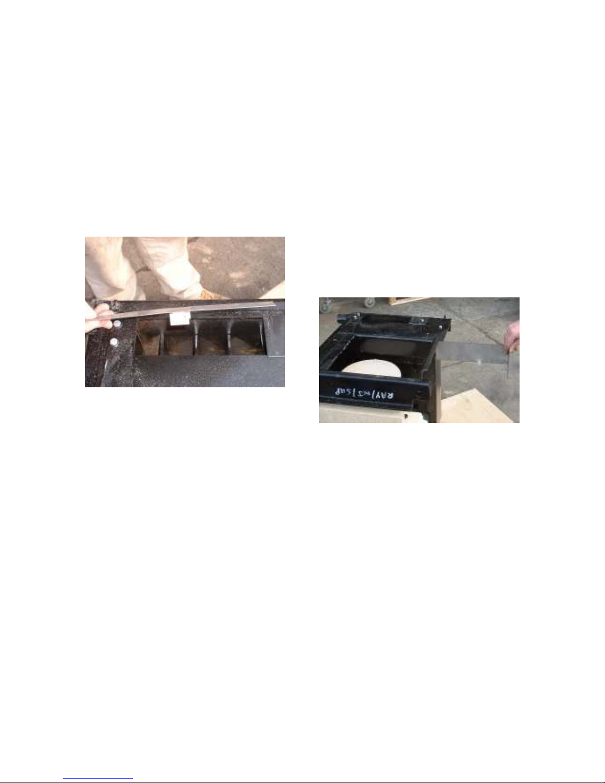
LLEEAANN TTHHEE
B
B
OOIILLEERR AANNDD
F
F
LLUUEEWWAAYYS
S
..
Scrape and wire brush all the internal
boiler surfaces including the back flue
ways.
Thoroughly clean all the internals of
the cooker/boiler, if there are any
large deposits of scale or vitrified
coke chip it off and leave the
appliance surgically clean.
2288.. R
R
EEMMOOVVEE
T
S
T
HHEE
S
LLIIDDIINNGG
D
D
AAMMPPEER
R
..
Seal the opening left by the sliding
damper with fire cement.
If you are going to fit the optional
flue box silencing kit, fit it now using
the instructions in the kit.
F
T
O
O
B
E
2299.. F
IITT
T
HHEE
O
VVEERR
O
VVEENN
B
AAFFFFLLE
..
By standing it on top of the oven
casting and pushing it up to the rear
right hand corner of the hot plate
opening.
Its longest leg running towards the
fire box and its shortest leg running
across the short side of the opening
towards the front of the appliance
NOTE if you are converting a Nouvelle
the long leg of the baffle will need
trimming back (with either a hacksaw
or heavy duty tin snips) to a length of
140 mm.
Secure the baffle with a fillet of fire
cement.
Page 19
19
U
T
H
S
S
3300.. U
SSIINNGG
T
HHEE
H
OOLLEE
S
AAWWS
..
Mark out and drill the access panel.
At the bottom left hand side of the
panel -:
One hole at 16mm dia. for the power
in. (small strain)
One hole at 29mm dia for the oil
supply. (large strain) and fit the cable
strains.
2
A
112
P
LLAATTE
P
A
B
.. B
E
..
OOAARRDDSS
A
A
NNDD
C
LLOOSSUURREE
C
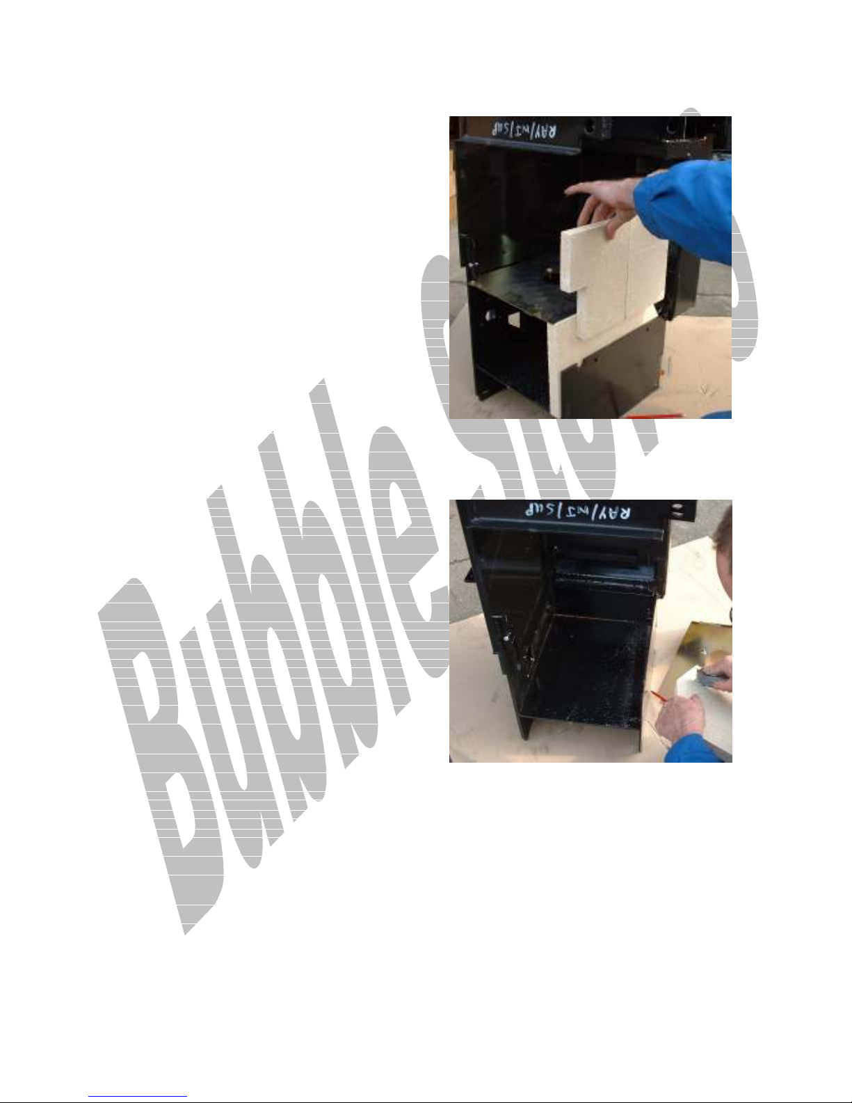
Before permanently fitting the
boards and closure plate try a dummy
run, some trimming work may be
required, if not PROCEED and fit
them permanently using plenty of
sticky wet firecement.
F
T
T
O
S
11.. F
IITT
T
HHEE
T
WWOO
O
VVEENN
S
IIDDEE
F
F
IIRREEBBOOAARRDDS
S
..
Clean out the socket into which they
will fit and apply fire cement to bed
them on.
Remember when fitting the base
boards through which the flame tube
projects, temporarily fit the head, to
make sure all the holes are
concentric, and remain that way
through the fire cementing
procedure.
Page 20
20
22.. F
F
IITT
T
C
T
HHEE
C
LLOOSSUURREE
P
P
LLAATTE
E
..
33.. F
B
B
OOAARRD
F
T
A
P
S
IITT
D
..
T
HHEE
A
SSHH
P
IITT
RR..HH.. S
IIDDEE
I
I
NNSSUULLAATTIINNGG
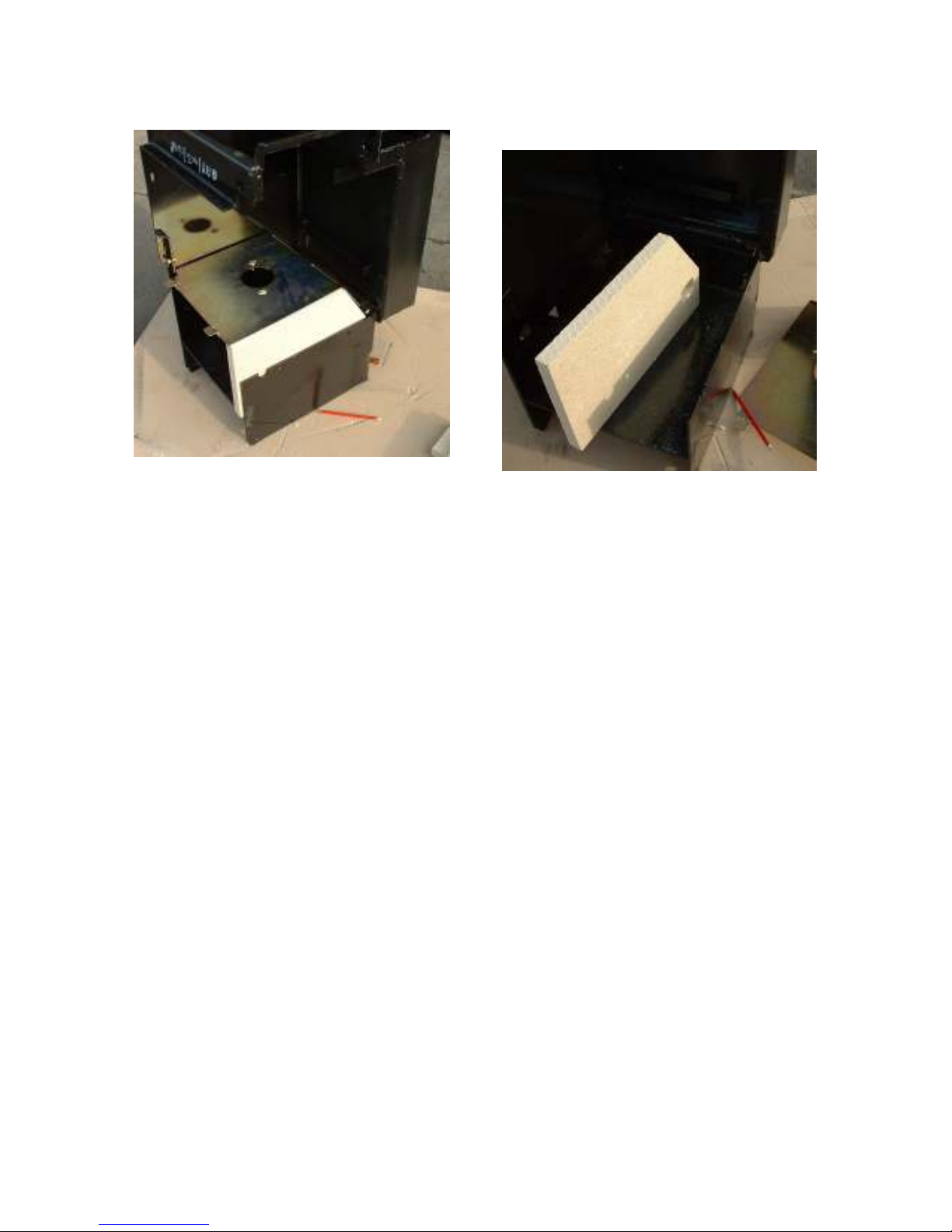
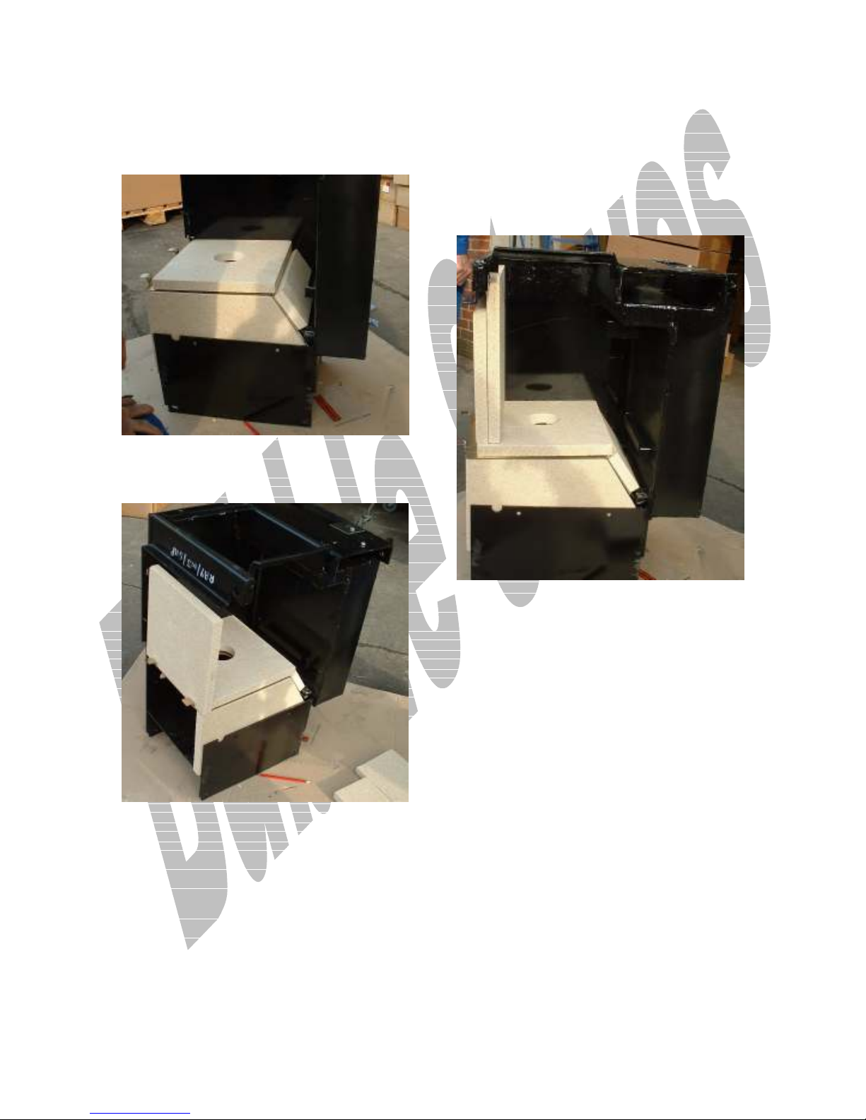
Rest the rear lugs of the closure
plate on to the inner cast protrusion
of the appliance front casting.
Drop the front on to the protruding
ledge just beneath the lower rear
boiler flue outlet.
Make sure that there is a gap of
approx 8 mm between the boiler and
the closure plate at the L.H. side of
the plate.
It will be necessary to trim out the
back of the board with a Stanley
knife to accommodate the protrusion
of the rear grate support (See fig 11)
and any inward distortion of the lower
R.H. side panel (LEDGE "A" fig 11)
due to overheating.
In some cases it is also possible for
the ashpit base to be bowed up
through heat distortion, if it is trim
the board to suit.
The board must fit snugly up to the
side of the ashpit as the outer edge is
masked using the stainless steel trim.
SEE Fig 12, the angle trim should be
made to fit up to the right hand side
of the ashpit to mask the gap
between the ashpit side board and
the side casting.
It should be fitted neatly and
vertically so as to finish off the
appearance of the ash pit area, use
the silicone sealant as an adhesive and
pin through the side.
Page 21
21
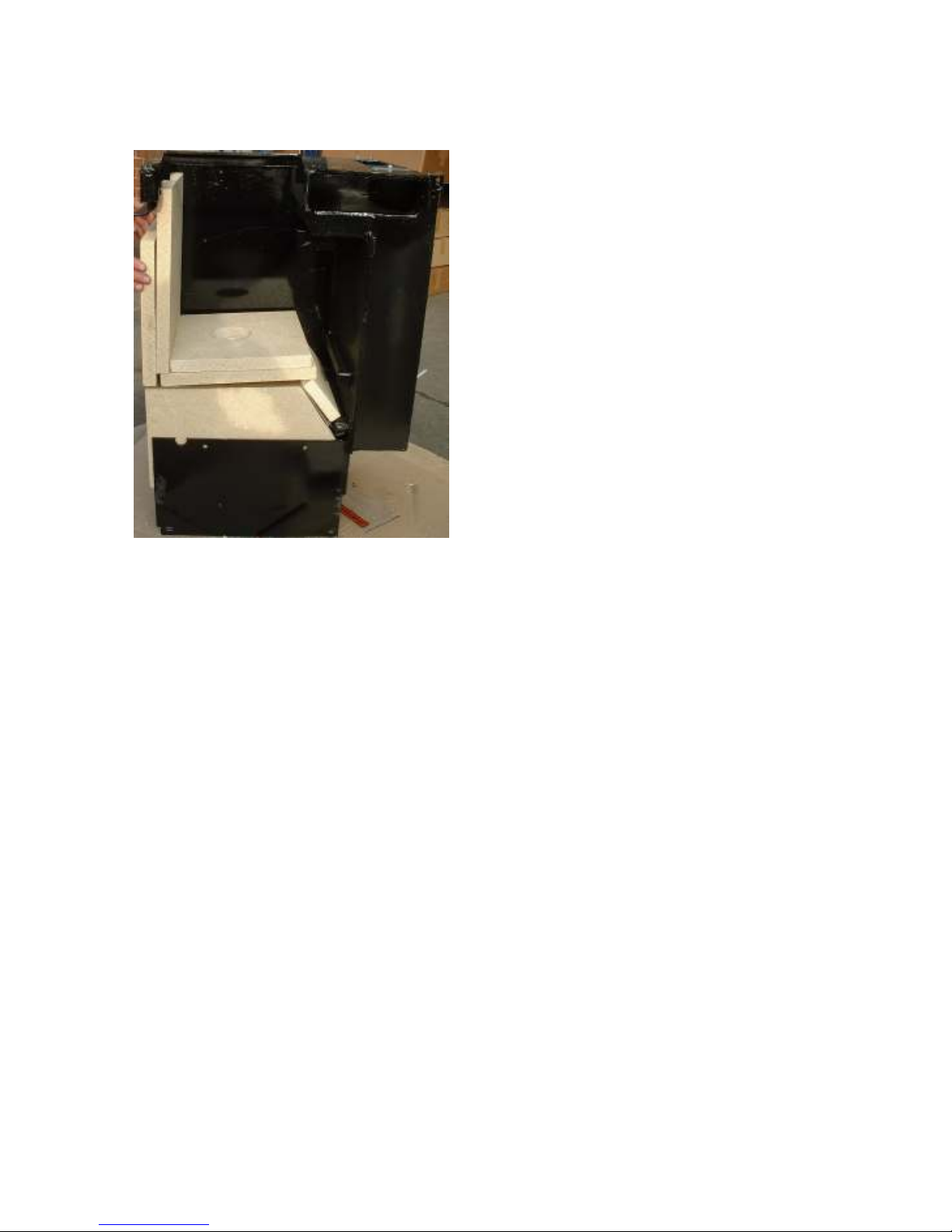
Apply a good wedge of fire cement at
the boiler end of the board and
F
T
44.. F
IITT
P
T
HHEE
P
RRIIMMAARRYY
D
D
RROOOOPP
N
N
OOSSEEDD
B
B
OOAARRD
D
.
.
(See Fig 12 )
F
T
66.. F
IITT
T
HHEE
P
P
RRIIMMAARRYY
F
F
RROONNTT
B
B
OOAARRD
D
..
Illustrated in 5.
(See Fig 12 also )
Firecement at the edges.
F
T
88.. F
IITT
T
HHEE
S
S
EECCOONNDDAARRYY
F
F
RROONNTT
B
B
OOAARRD
D
.
.
F
T
B
55.. F
IITT
B
AASSEE
C
C
LLOOSSUURREE
T
HHEE
P
P
LLAATTEE
B
B
OOAARRD
D
..
Making sure that a good fillet of
silicone sealant has been applied to
the top surface of the metal closure
plate around the center boss, wiping
any excess away.
(See Fig 12 )
Firecement up the verticals
Apply a good wedge of fire cement on
the closure plate and
Page 22
22
99.. F
B
B
OOAARRD
F
IITT
D
T
..
T
HHEE
S
S
EECCOONNDDAARRYY
C
C
LLOOSSUURREE
P
P
LLAATTEE
Fasten the two securing screws which
bolt the head flange up to the closure
plate.
If the ashpit base is bowed up
through heat distortion, pack up
under the stick on rubber feet until
the base plate is sitting free form
the distortion.
Firecement around the edges.
1100.. P
P
EERRMMAANNEENNTTLLYY
F
F
IIRREECCEEMMEENNT
T
..
Firecement the whole lot permanently
into place pushing the cement firmly
into all the gaps and smoothing off
both above and below the closure
plate and up the sides of the front
boards.
Using a putty knife or similar, take
care to smooth off perfectly flat
the vertical and horizontal fillets of
firecement at the left hand side of
the combustion chamber as they will
form a base and sealing joint for the
summertime baffle boards which are
now available.
1111.. F
F
IITT TTHHEE
B
B
UURRNNEER
R
..
1122.. P
P
LLUUGG IINN TTHHEE
T
T
HHRREEEE
P
P
G
P
LLUUG
..
P
IINN
Plug in the three pin plug from the fan
and make sure that the plug to the
fuel pump is connected
B
2
S
B
.. S
IILL
F
F
R
EEEED
EERRVVIICCEESS
..
D
..
112
B
UURRNNEER
B
O
11.. O
I
I
NNTTOO
T
HHEE
T
Fit the flexi oil feed pipe and the
remote fire valve phial and capillary
through the cable support in the
lower plastic plug ready to connect
up.
O
22.. O
I
IILL
I
SSOOLLAATTIIOONN
V
V
AALLVVE
E
..
Fit the oil isolation valve at the
termination of the flexi oil feed pipe
( 1/4" male bspt)
O
33.. O
IILL
P
P
IIPPEEWWOORRKK
T
T
P
OO
P
RREESSSSUURREE
J
B
J
EETT
B
UURRNNEERRS
S
..
Because there is a motor and a fan in
the burner unit, some vibration may
be transmitted through the pipework.
If the pipework is in contact with any
sharp edges fretting can occur, to
prevent this apply silicone sealant at
any potential hazard points.
Slide the burner into the ashpit and
push the combustion head up through
the closure plate.
Check that the oil supply line has a
suitable filter, firevalve and does not
have the potential for air locking.
Page 23
23
P
I
N
44.. P
OOWWEERR
I
N
..
Fit the mains feed cable through the
air inlet tube and thread them
through the cable support in the
upper plastic bung ready to connect
up.
2
C
112
C
.. A
A
BBOOUUTT
T
T
T
HHEE
HHEERRMMOOSSTTAAT
T
T
..
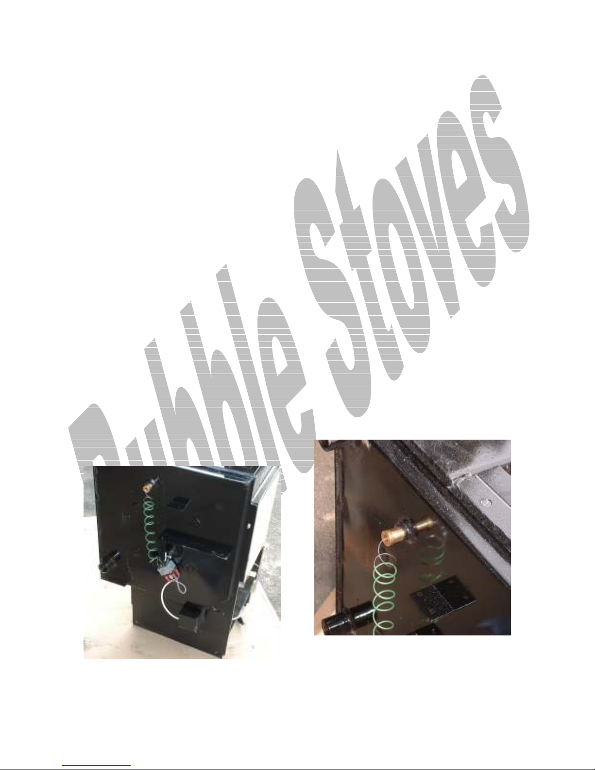
One two stage thermostat is supplied
and it is connected to the control
module via a two pole plug.
The thermostat has a sensing bulb
and a small diameter partially
insulated, soft copper capillary tube
which should be carefully unwound
and neatly fitted, making sure that
the capillary tube and bulb cannot be
bent, trapped or damaged, remember
damage to the tube or bulb will
prevent the thermostat from
functioning .
The thermostat is mounted in the
same place as the old solid fuel stat
on the special bracket provided and
secured by the fastener provided.
Drive to the new stat is exactly the
same as before using the existing
flexi and the small brass drive
adaptor provided with the conversion,
which fits into the spring retained
drive of the flexi and onto the
spindle of the new stat. If the
existing drive is stiff, lubricate it
with WD40, when you are happy with
the drive, synchronise both the dial
and the new stat by turning the dial
to zero, and the new stat fully
anticlockwise, at this stage glue the
brass drive adaptor onto the new
stat spindle (2 part epoxy) and leave
it to set.
The new thermostat controls both the
running temperature and provides the
safety cut out at 85 deg C.
Normally the user will achieve the
running temperature required by
setting the control knob as required.
11.. F
F
T
T
HHEE
N
N
EEWW
IITT
P
P
HHIIAAL
L
..
Into the make up bush and run the
link wire and plug through the air inlet
and into the ash pit to be plugged into
the control module.
Page 24

24
22.. R
R
EEFFIITT
T
A
T
HHEE
A
CCCCEESSSS
P
P
AANNEEL
L
..
22.. H
H
B
EEAATT
B
AALLAANNCCIINNGG TTHHEE
S
S
YYSSTTEEM
M
..
It is assumed that the installer has
connected up the oil supply from the
tank in the correct manner.
Connect the three pin power supply
after first checking for correct
polarity.
L
T
33.. L
44.. F
55.. C
66.. C
77.. B
IINNEE
F
V
IITT
V
C
OONNNNEECCTT
C
OONNNNEECCTT
B
AACCKKFFIILLLL
C
T
HHEE
C
EENNTTIILLAATTIIOON
T
T
T
T
A
A
HHIIMMNNEEY
N
C
HHEE
C
HHIIMMNNEEY
E
HHEE
E
LLEECCTTRRIICCAALL
RROOUUNNDD
Y
..
..
Y
..
S
Y
UUPPPPLLY
..
S
T
L
T
HHEE
L
IINNEERR
If the flue is exposed backfill around
it with loose fill vermiculite.
F
A
D
88.. F
IITT
C
1133.. C
D
OOWWNN
D
D
RRAAUUGGHHTT
A
NNTTII
OOMMMMIISSSSIIOONNIINNG
C
L
C
OOWWL
G
..
Commissioning takes the form of
three separate activities-:
1. Setting the burner up.
2. Heat balancing the appliance to the
users system.
3. Final check of the complete
installation.
S
11.. S
EETTTTIINNGG TTHHEE
B
B
UURRNNEERR
U
P
U
P
..
1a. Nozzle .4 x 80 Deg Hollow
1b. Pump Pressure 9 Bar (130 P.S.I.)
1c. Gross Output 17.6 kW
1d. Net Output 14.08 kW
1e. Flue Gas Flow .0027 m/s.
Setting up the appliance to perform
as per our requirements ( Heat
balancing)
33.. L
L
IIGGHHTTIINNG
G
..
Make sure the appliance is fully
assembled except for the hot plate,
do not fit the baffle box as it is
necessary to view the flame.
Carry out electrical safety tests in
line with IEEE and OFTEC
requirements
Polarity.
Short circuiting.
Earthing.
Turn the oil on and check for leaks.
33..11.. T
T
B
B
LLEEEEDD
T
T
HHEE
OO
P
P
UUMMP
P
..
Take great care when bleeding the
pump, It is a single cylinder
reciprocating device and if repeated
lockouts occur, due to lack of fuel
caused by air locking, it can soon be
damaged. If the pump runs without oil
it will make a quite loud and rapid
rattling noise and permanent damage
in the form of a subdued rattling will
occur.
Use the 1/8" BSPT plug in the tee
fitting connected to the outlet of the
pump.
S
T
33..22.. S
EETT
T
HHEE
C
C
OONNTTRROOLL
S
T
S
TTAAT
..
Turn the stat fully off .
S
T
T
C
K
33..33.. S
EETT
HHEE
IIMMEE
T
T
C
LLOOCCK
..
Make sure that the time clock is
calling.
Page 25
25
C
T
33..44.. C
HHEECCKK
B
T
HHEE
B
UURRNNEERR
A
S
A
IIRR
S
HHUUTTTTEER
R
..
The burner air shutter has been set
at the factory and should be
satisfactory for test firing.
33..55.. P
P
RREEPPAARREE
AA S
S
AAMMPPLLIINNGG
P
P
OOIINNT
T
..
Drill a hole suitable for your analysis
probe in the inner cover of the
vertical rear boiler cover plate.
After the tests plug the hole with a
Dwyer test point plug.
With the hot plate removed it will be
possible to see the burner ignite but
before attempting ignition make sure
that there isn't any excess light in
the combustion chamber, to affect
the photocell.
I
33..66.. I
GGNNIITTEE
T
B
R
T
HHEE
B
UURRNNEER
..
Turn the stat ON and from a
respectable distance you will see the
burner go through an ignition
sequence and ignite, it is unlikely that
the burner will need bleeding although
it may need two attempts at ignition.
Failure to ignite will cause the flame
failure button on the controller to
illuminate, after a short time push the
button in to reset the controller and
repeat the process again until ignition
occurs.
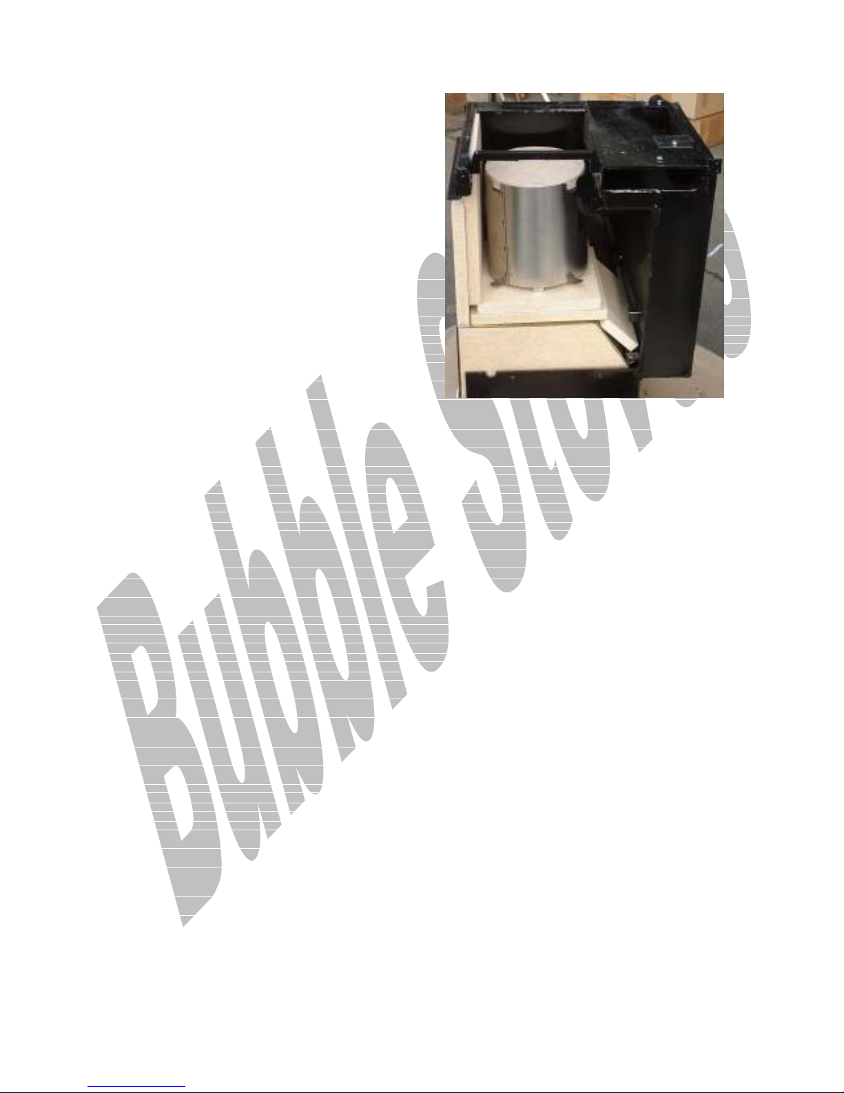
The baffle is fitted over the flame
tube as illustrated.
There are two rectangular cut outs in
the vertical sides of the baffle which
can be positioned to point to -:
1. The rear and left hand side for
intensive water heating or wintertime
running
Or
2. The front and right hand side for
intensive cooking or summer time
running.
Or
3. To the right and rear for
intermediate running.
F
T
B
B
33..77.. F
IITT
HHEE
AAFFFFLLEE
T
B
X
OOX
B
..
When you are happy with the flame
picture, turn the burner off and
isolate the mains electricity before
you fit the baffle box and the hot
plate.
Make sure that the baffle is set up
for either summer or winter running.
It can be set up to bias the flame to
the oven or the boiler or an
intermediate position.
Page 26

26
33..88.. F
F
IITT TTHHEE
H
P
E
P
LLAATTE
..
H
OOTT
When refitting the hot plate make
sure that the ceramic rope seal which
fits over the top of the cooking /
heating damper frame is correctly
fitted, otherwise the heat balance of
the appliance will be seriously
affected and the performance will not
be satisfactory.
T
S
F
G
33..99.. T
OO
S
EETT
F
OORR
G
OOOODD
C
C
OOMMBBUUSSTTIIOON
N
..
Do not attempt to take any flue gas
readings until the burner has been
running for at least three quarters of
an hour after which time you should
check that the flue vacuum conforms
to our stated requirements.
Remove the plug you have fitted in
the rear boiler access cover plate and
insert your analysis probe.
Make sure that the chrome cook heat
lever is in the heat position as
opposed to the cook position.
By way of minor adjustments to the
fuel air ratio, set the burner to give a
CO2 reading of 10.5% at a smoke of
between 0 and 1. (You may well get a
higher CO2 than 10.5%)
Note after you have finished with the
analysis; fit the rear boiler baffle
over the outlet from the rear boiler
flue ways.
With a flue vacuum of between .02" &.
05" w.g., the following analysis results
should be obtained: -
Smoke between 0 and 1
CO2 = 10.5%
O2 =5 - 6%
With the appliance running on a
55,000 BTU system in its heating
mode the efficiency should be
between79% and 82% and on average,
the system should come up to a
temperature of around 65 deg C with
an oven of around 170 - 190 deg C in
about 40 to 55 minutes.
33..1100.. C
C
OOMMBBUUSSTTIIOONN
A
R
A
IIR
..
Combustion air is adjusted via the air
control damper on the fan unit which
when set can be locked in place.
If you are having difficulty bringing
the burner on to the smoke, try
increasing the fuel pressure slightly
until you achieve 0 - 1 on the bacharac
scale.
When you are happy with these
readings carry out a second test in
the flue pipe where you will see
because of slight air leaks into the
appliance a reduced C02, but still
around 8%.
Sampling from the access plate at the
rear outlet of the boiler
T
33..1111.. T
OO
A
A
DDJJUUSSTT
T
P
P
UUMMPP
P
P
T
HHEE
RREESSSSUURRE
E
..
There are two type of pump fitted to
Flexaflame burners.
Nippon
The oil pump pressure on the Nippon
pump is adjusted via the screw to the
left of the fuel entry position. The
burner is set at the factory at a
pressure to suit the appliance being
converted.
Page 27

27
Fully in and three quarters of a turn
out is equal to 10 Bar, each quarter of
a turn out is equal to one bar
reduction. If you lose your position
with the adjustment, get back to the
10 bar start point.
Taisan
The oil pump pressure on the Taisan
pump is adjusted via the setscrew and
locknut to the Right of the fuel entry
position.
The burner is set at the factory at a
pressure to suit the appliance being
converted.
F
C
S
44.. F
IINNAALL
C
HHEECCKKS
..
Commissioningh checks should be
carried out on the following-:
F
T
K
44..11.. F
UUEELL
T
AANNK
..
Check for leaks-stability-heightposition-vent.
I
44..88.. I
SSOOLLAATTIIOONN VVAALLVVE
E
..
Check for function, convenience of
positioning and leaks.
44..99.. E
E
LLEECCTTRRIICCAAL
L
..
Check for correct fusing, location and
specification of any isolation devices.
44..1100.. V
V
EENNTTIILLAATTIIOON
N
..
Make sure that adequate ventilation is
provided.
44..1111.. C
C
HHIIMMNNEEYY
S
S
YYSSTTEEM
M
..
Chimney system should be checked to
make sure that it complies with the
relative standards, regulations and all
other instructions given.
44..1122.. C
C
HHEECCKK CCOONNTTRROOLLSS
F
F
UUNNCCTTIIOON
N
..
Check correct hot condition
functioning of water heating system
and all controls.
44..1133.. I
I
NNSSTTRRUUCCTT
U
R
U
SSEER
..
F
L
UUEEL
..
44..22.. F
Fuel- check for correct grade
F
R
IILLTTEER
..
44..33.. F
Is it fitted?
Check for function and leaks.
S
44..44.. S
IITTEE
G
G
LLAASSSS OORR
T
T
AANNKK
G
G
AAUUGGE
E
..
Check for function and leaks.
44..55.. O
O
IILL LLIINNE
E
..
Check for function, positioning,
material suitability and leaks.
.
44..66.
F
F
IIRREE VVAALLVVEES
S
..
Check for function and leaks.
44..77.. T
T
HHRROOUUGGHH
W
W
AALLLL
S
S
LLEEEEVVIINNG
G
..
Check that it is fitted and sealed
Ensure that the customer is
instructed on the basic use of the
appliance, timers, controls and oil /
electrical isolation devices if fitted.
The importance of regular
maintenance.
Commissioning should not be signed
off unless the commissioning engineer
is satisfied that all the work done
complies with the relative standards
and regulations detailed within this
document.
.
44..1144.
V
V
EENNTT TTHHEE
A
A
SSHHPPAANN
D
R
D
OOOOR
..
This work should not be carried out
unless the customer is 100% happy
with the conversion.
Page 28

28
Once the work has been carried out it
is not possible to convert the
appliance back to solid fuel, should
the need ever arise.
The objective of the activity is to
allow a cooling stream of air to pass
vertically up behind the ashpit door
and stop the build up of hot air in the
ashpit.
This will have a beneficial effect on
the longevity of the burner as it will
be operating in a much cooler
environment.
This information will form part of a
record of the installation and will be
the first point of reference by our
staff, for any claims made under
the equipment warranty.
The warranty covers PARTS ONLY
for a period of ONE YEAR and is
conditional upon all the requirements
of our installation and commissioning
instructions being fully adhered to.
I
N
I
TTEEMMSS
L
L
AABBOOUUR
C
N
OOTT
C
OOVVEERREEDD
R
..
U
U
NNDDEERR TTHHEE
W
W
AARRRRAANNTTYY
The door should be removed and
placed upon a bubble pack support to
prevent damage to the enamel
surface.
Using a 4inch disc grinder set up with
a flap wheel, grind away an area as
detailed in Fig 13 and refit the door.
W
1144.. W
AARRRRAANNTTYY
..
Ensure that the warranty registration
documentation is returned to
Harworth Heating Ltd.
It will not be possible to deal with
any warranty claims unless we hold
on our Data Base, details from a
correctly filled in warranty
commissioning form.
The form must arrive back at our
works within two weeks of the burner
being correctly commissioned.
When the warranty form is received
at our works details from it will be
entered on to our warranty
registration Data Base.
T
T
RRAAVVEELLLLIINNGG TTIIMME
C
C
OONNSSEEQQUUEENNTTIIAALL LLOOSSSS OORR DDAAMMAAGGE
N
N
B
B
S
OOZZZZLLEES
AAFFFFLLEE KKIITTSS AANNDD
..
E
..
E
..
I
I
NNSSUULLAATTIIOONN
B
B
OOAARRDDS
S
..
Damaged due to faulty installation and
or faulty commissioning of the
appliance.
D
D
AAMMAAGGEE TTOO TTHHEE
F
F
UUEELL
P
P
UUMMP
P
..
Caused by air locks in the fuel line or
lack of fuel.
If the fuel pump runs without oil. It
will make a loud and rapid rattling
noise.
If this occurs permanent damage in
the form of a subdued rattling will
occur.
F
1155.. F
AAUULLTT
F
IINNDDIINNG
F
G
..
Fault finding procedures are covered
under a separate sheet.
Page 29
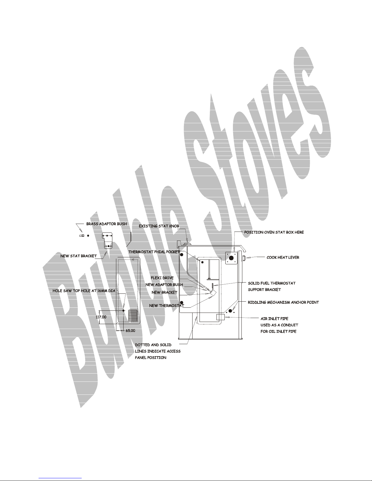
29
S
1166.. S
EERRVVIICCIINNG
G
..
After a conversion the internal metal
surfaces of the boiler shed
considerable amounts of scale, The
scale can drop into the combustion
head and cause damage to it.
To prevent this we recommend that a
chargeable, first quick service be
carried out, to clean away the scale.
The scale shedding lasts for about 6
to 9 months, gradually decreasing.
Thereafter servicing should be
carried out at six monthly intervals.
Service engineers should request a copy of the servicing schedule from our sales
desk.
Schedules will also be available from our web site http://www.oilstoves.co.uk
F
1188.. F
IIGGUURREES
S
..
Additional information follows in the form of illustrations.
B
S
T
FFIIGG 1100 B
OOIILLEERR
S
TTAAT
View looking at the left hand side panel.
Page 30
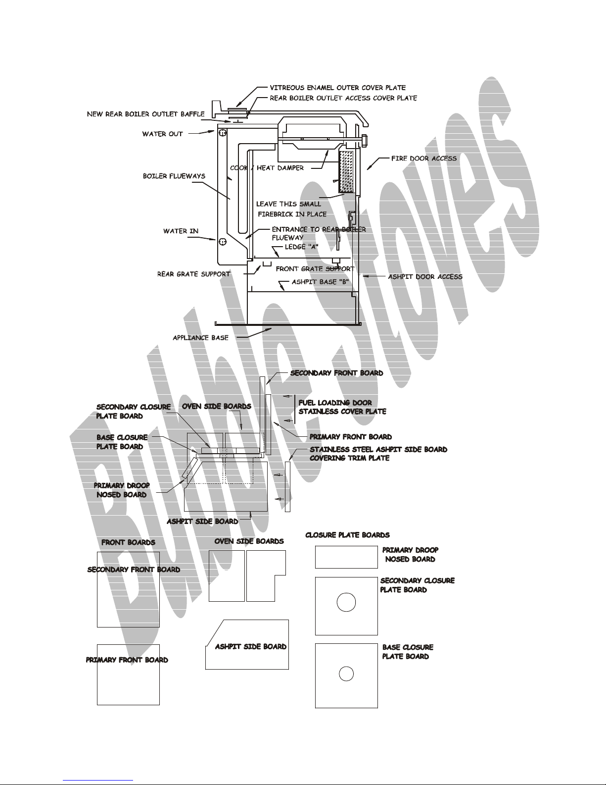
25
FFIIGG 1111 S
F
IIGG
1122 B
B
F
S
EECCTTIIOONNAALL
D
OOAARRDD
D
D
D
EETTAAIILLS
EETTAAIILLS
S
S
Page 31
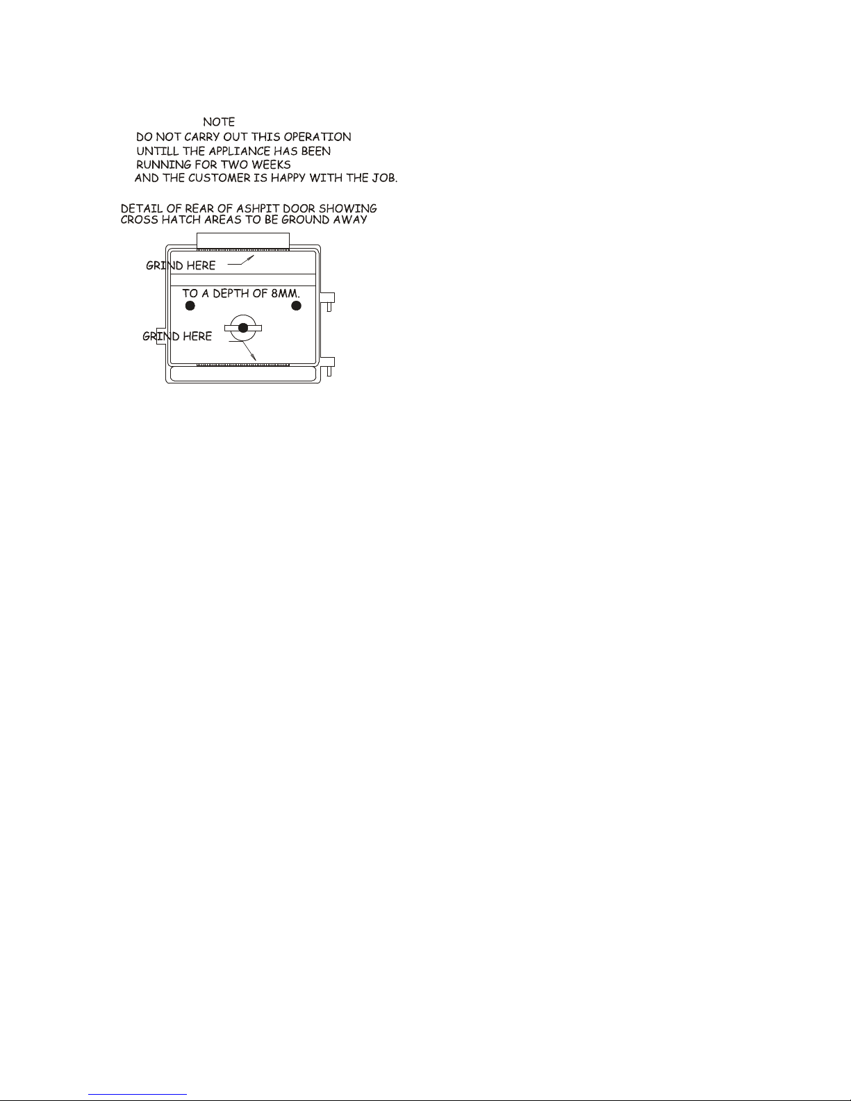
26
F
G
D
R
F
IIGG
1133 G
RRIINNDD
D
OOOOR
Page 32
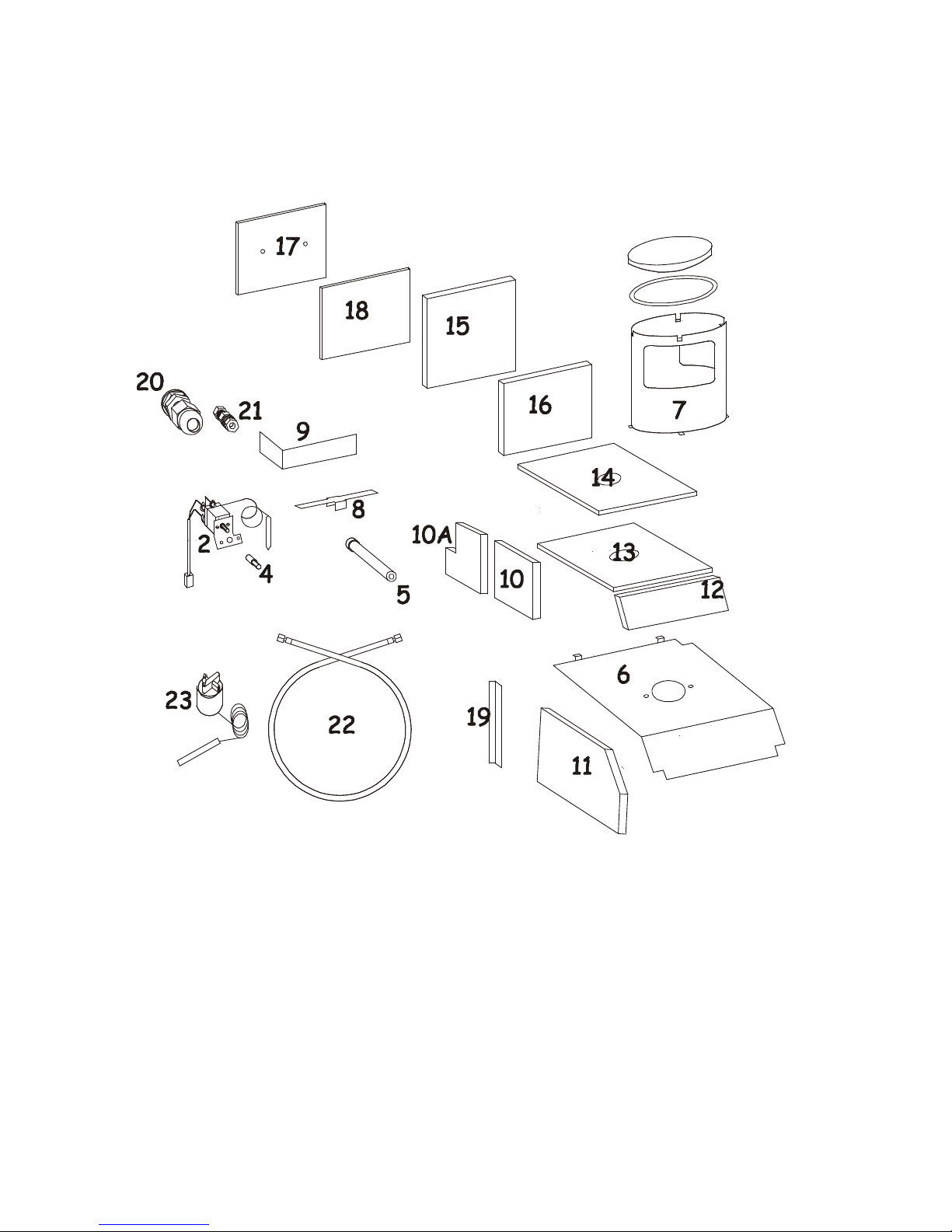
26
F
IIGG
1144 E
E
XXPPLLOODDEEDD
F
P
P
AARRTTSS
L
T
L
IISST
Take care when viewing the parts list detailed as it is drawn looking from the back
of the appliance.
Page 33
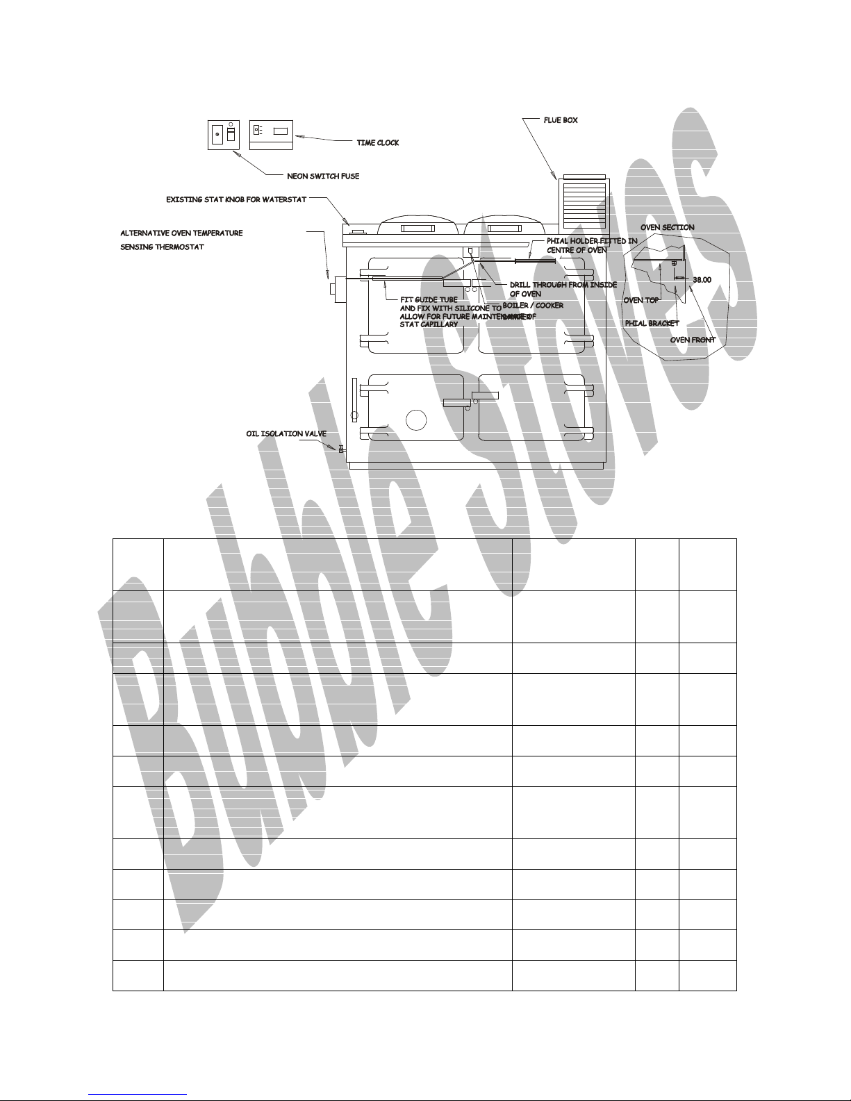
27
F
O
S
F
IIGG
1155 O
VVEENN
S
TTAATT
D
D
EETTAAIILLS
S
P
P
AACCKKIINNGG
L
T
L
IISST
Item
No
1 Burner assembly complete 77-10-
Description PART
NUMBER
Qty Check
1
001/MB1
2 Bi pole stat assembly 77-01-007 1
3 Mounting Plate and fasteners for Bi pole stat
1
assembly.
4 Flexi Drive bush adaptor 87-01-010FDB 1
5 Brass make up bush for Bi Pole stat phial 77-01-201 1
6 Closure plate with fasteners 87-18-
1
010CD/V2
7. Circular Baffle Kit complete 87-01-010/3 1
8. Rear Boiler outlet baffle 87-01-010/BB 1
9. Over oven baffle 87-01-010/OB 1
10 Insulation Boards Oven side board 87-19-010A 1
10A Insulation Boards Oven side board with cut
87-19-010B 1
Page 34

28
out.
11 Insulation Board Right hand ash pit side
87-19-010C 1
board
12 Insulation Board Droop nose board 87-19-010E 1
13 Insulation Board Base closure small hole
87-19-010G 1
77MM (first board)
14 Insulation Board Base closure large hole
87-19-010F 1
86MM (second board)
15 Primary Front Insulation Board 87-19-010H 1
16 Secondary Front Insulation Board 87-19-010I 1
17 Metal Plate for lining the back of the fuel
87-17-010FHD 1
loading door
18 Metal Plate for fitting into the blocked off
87-17-010DW 1
fuel loading door opening.
19 Stainless steel decorative trim. 87-17-010TP 1
20 Cable Strain for fuel supply 77-01-023 1
21 Cable strain for electrical supply RS392-056 1
22 Flexi oil supply pipe 77-01-017/A 1
23 Fire Valve 77-07-004/C 1
24 User instructions 1
25 Installer instructions 1
26 Flexaflame service burner book 1
© HARWORTH HEATING LTD 30.6.98
This publication may not be copied by any means, without written permission from the authors.
This product is subject to continuous development and improvement and it is consequently acknowledged that due to this
process there may be some omissions and errors.
This publication is intended only to assist the reader in the use of this product and therefore Harworth Heating Ltd shall
not be liable for any loss or damage whatsoever arising from the use of any information, error or omission found in this
guide.
Page 35

29
Only approved personnel, WHO HAVE BEEN SUITABLY TRAINED, must carry out
maintenance on this product.
 Loading...