

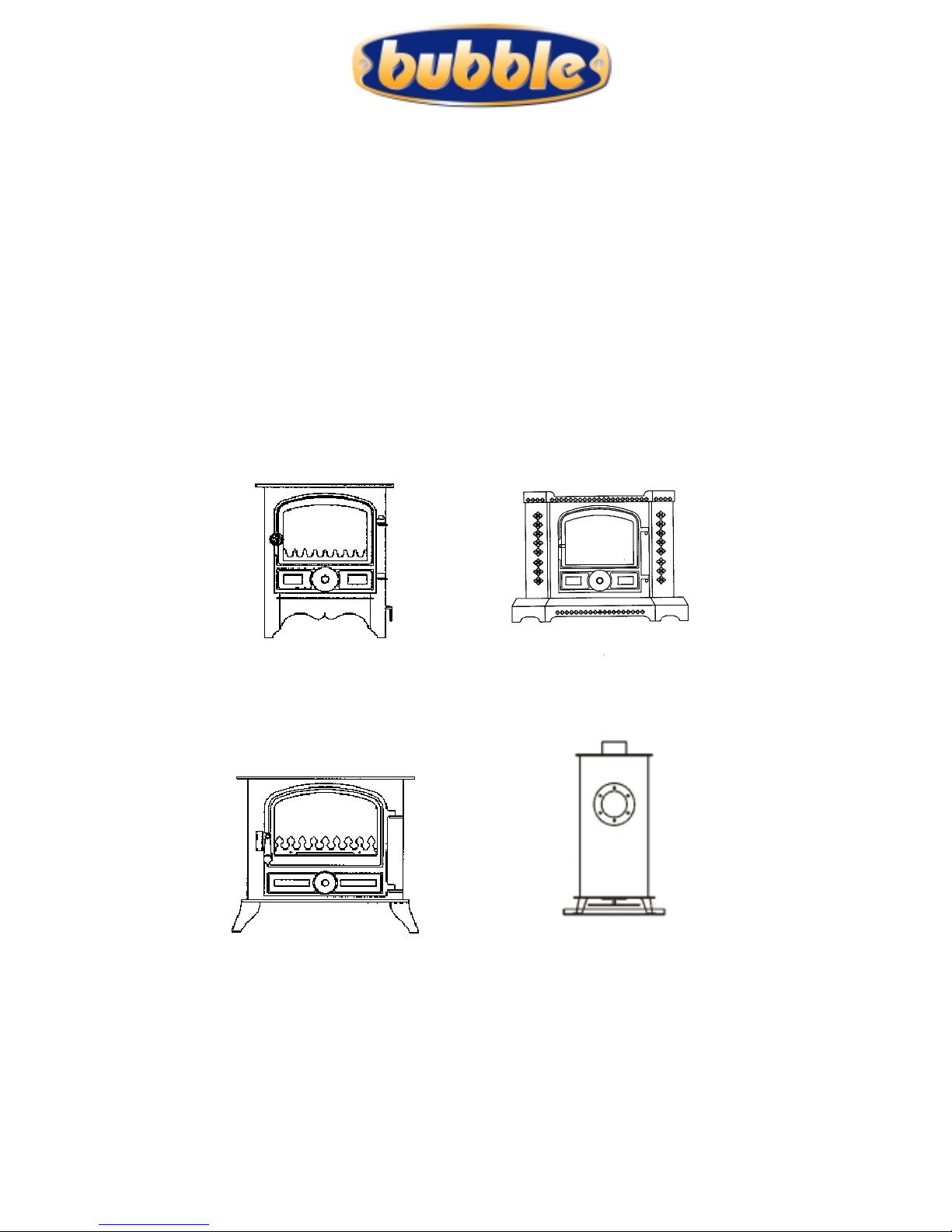
Bubble Bb1, Corner Stove, Bb2, Bubble PJ 12/24 volt dc, Bubble PJ 230 volt ac Service Instructions Manual
Page 1
B
B
UUBBBBLLEE
M
M
AARRIINNEE
S
S
TTOOVVEES
S
S
S
EERRVVIICCEE
I
I
NNSSTTRRUUCCTTIIOONNSS
Keep with the appliance at all times
http://www.oilstoves.co.uk/
Page 2

I
I
NNDDEEX
X
Index ________________________________________________ 2
1.Warnings ____________________________________________ 4
1. Hot Burner ____________________________________________ 4
2. Post Service ___________________________________________ 4
3. Health and Safety_______________________________________ 4
4. Control of Substances ____________________________________ 4
2. Servicing Pre-Amble___________________________________ 4
Round Stoves And Trian gul ar Stoves POT Section a l Draw ing.__________ 5
BB1, Belfort And BB2 Pot Sectional Drawing______________________ 6
3. Servicing ___________________________________________ 6
1. Poor Oil Flow ___________________________________________ 6
2. Servicing Dirty Burners___________________________________ 7
2-1 Cleaning Procedure______________________________________ 8
2-3 Remove Drain and Clean the Oil Control Valve __________________ 9
2-4 Check that oil flows freely into the pot. _____________________ 10
2-5. Check for Good Ignition ________________________________ 10
2-6 Adjust the high and low firing rate. ________________________ 10
3. Adjust Descaling Device Fig 1______________________________ 10
4. Clean the oil feed Pipe ____________________________________11
5. Check that the Oil Flows Freely into the Pot____________________11
6. Check for Good Ignition___________________________________11
7. Check the Low and high Fire Flame BB1, BB2 and BELFORT ________ 12
8. Check the Low and high Fire Flame (CORNER AND ROUND STOVE)__ 13
9. Check Action Of OPERATING AND Safety Thermostats__________ 14
10. Clean the Stove Internals________________________________ 15
11. Clean the Stove Externally _______________________________ 15
12. Check the Door Seals___________________________________ 15
13. Clean the Door Glass ___________________________________ 15
14. Adjust the Door Fastening._______________________________ 16
15. Stoves with Barometric Dampers – Check Function______________ 16
16. Stoves with Combustion Air Restrictors – Check Function_________ 16
17. Check if the Holes in the Pot are Free from Obstructions ________ 16
18. Check the coal kit _____________________________________ 17
19. Stoves with Electric Ignition _____________________________ 17
20. Ventilation __________________________________________ 17
21. Oil Tank, Valve Filters and Line____________________________ 18
22. Flue _______________________________________________ 19
4 Fault Finding ________________________________________ 20
1. Fuel Supply Problems ____________________________________ 20
Page 3

3
2. Air Supply Problems_____________________________________ 20
3. Commissioning Problems__________________________________ 21
4. Plumbing Circuit Design __________________________________ 21
5 Burner Does Not Light Easily ______________________________ 21
6 Stove Goes Out When The Central Heating Pump Is Turned Off_____ 21
7 Flue Vacuum___________________________________________ 22
8 Burner Quickly Carbons Up________________________________ 22
9 Oil Will not Enter the Pot_________________________________ 22
10 Check for Oil Leaks_____________________________________ 23
11 Check that the Oil is in the Correct Place 23
12 Flooded Oil Control Valve_________________________________ 23
13 Oil Smells____________________________________________ 23
14 Operating Flow Rates ___________________________________ 23
15 Burner Flares Up During Ignition ___________________________ 24
16 De-Flooding a Flooded Pot ________________________________ 24
17 Racing ______________________________________________ 24
Figures ______________________________________________ 25
Fig 2 Section of Bubble 1 Pot________________________________ 25
Fig 3 Section of Corner and Round Bubble Pot____________________ 25
Additional Publications___________________________________ 26
Installer info. ____________________________________________ 26
User info. _______________________________________________ 26
Parts lists _______________________________________________ 26
Price Lists _______________________________________________ 26
Other Info.______________________________________________ 26
Page 4

4
11..W
W
AARRNNIINNGGSS
11.. H
H
OOTT
B
B
UURRNNEER
R
Never try to re-light a hot burner, make sure that the burner is completely cooled
down before re lighting.
Make sure that any excess oil has been removed from the base of the burner before
lighting. (SEE 4-16)
22.. P
P
OOSSTT
S
S
EERRVVIICCE
E
Always check for oil leaks before leaving the site.
33.. H
H
EEAALLTTHH AANNDD
S
S
AAFFEETTY
Y
Always observe good health and safety routines (use suitable gloves and mask.)
44.. C
C
OONNTTRROOLL OOFF
S
S
UUBBSSTTAANNCCEES
S
Take great care when handling materials such as:
Insulation boards, glass fibre ropes, ceramic wool, artificial coals, kerosene oil, diesel oil
they are all irritants and suitable protective clothing such as disposable gloves dust masks
and protective goggles should be worn.
Wash off thoroughly after handling any of thes e materials.
Carefully dispose of redundant or surplus materials and always vac up after service or
installation work.
22.. S
S
EERRVVIICCIINNGG
P
P
RRE
E
--A
A
MMBBLLEE
1. Normally, you will only be called out to a Bubble stove when it doesn’t work correctly,
generally this means that it sooted up and won’t burn with a blue flame.
2. The main cause of stoves not working correctly is lack of oil flow and this can be
attributed to by-:
2-1. The stove not being installed and commissioned correctly from new.
2-2.A progressive build up of carbon deposits caused by lack of servicing or cleaning
3. Lack of oil flow, for whatever reason, stops the burner reaching the required
temperature to make the oil vaporise.
As a consequence, the incoming diesel burns as a single streak of dirty yellow flame rising
vertically from the oil inlet.
If the stove is allowed to run for any period of time in this condition, rapid sooting of the
stove and pot internals will occur.
This situation constitutes 99% of all call outs on bubble stoves and once it has
occurred it will be necessary to carry out a thorough clean out as per section 3-2.
Page 5
5
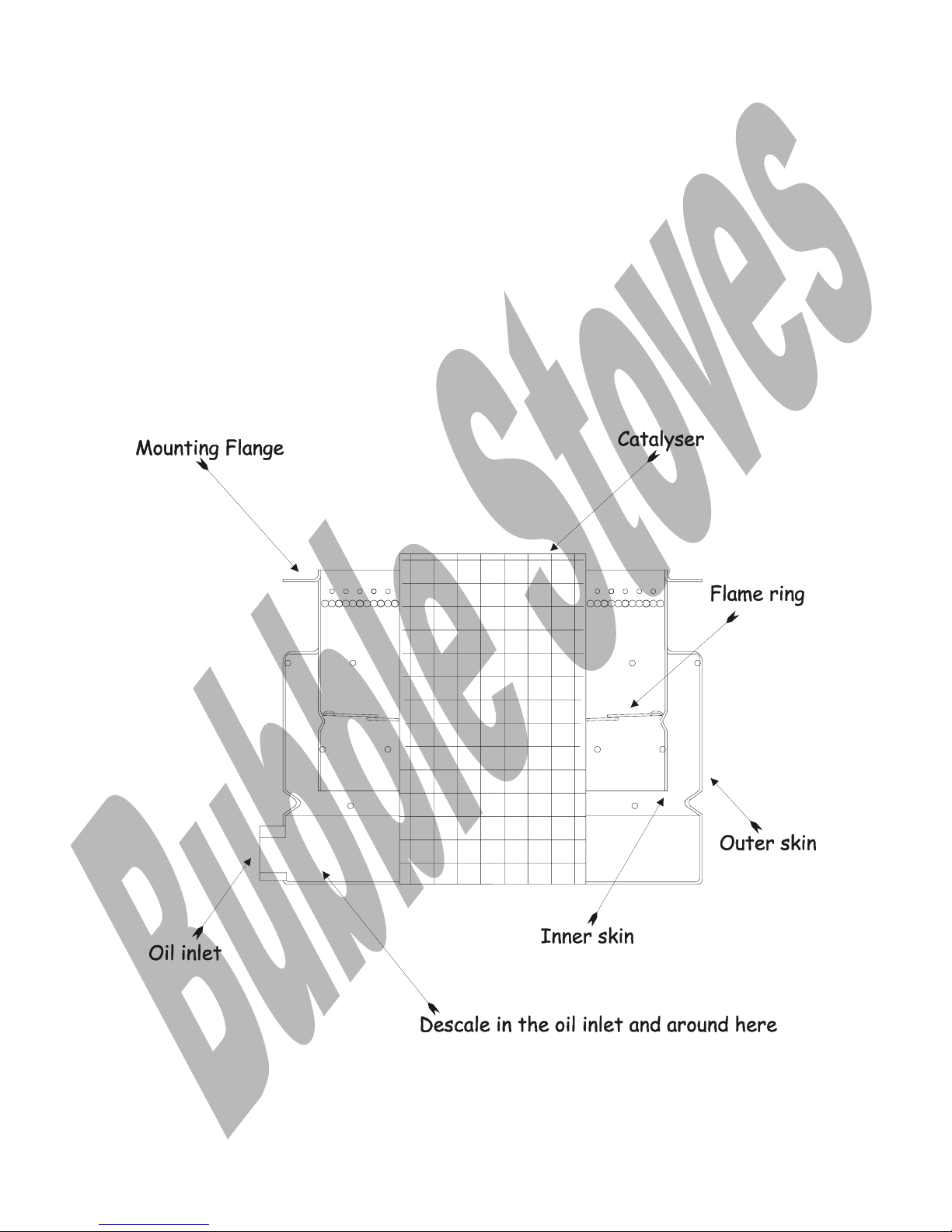
When the burner is adjusted correctly, sufficient oil will flow into it to allow vaporisation
to occur, at this point the diesel fuel will burn as a gas with the resultant clean blue
flame.
Note
We use two types of burner in our stoves, one has a single central catalyser and a flame
ring halfway down the pot and it is used on round stoves and triangular stoves.
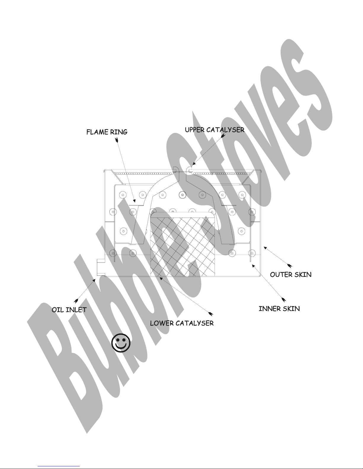
The other has a lower and upper catalyser and a flame ring, which fits on top of the upper
catalyser, used on BB1, Belfort and BB2.
Make sure that you know which burner you are working on; the bb1 burner is capable of
generating a taller blue flame on high fire and a smaller flame on low fire.
R
R
OOUUNNDD
S
S
TTOOVVEESS
A
A
NNDD
T
T
RRIIAANNGGUULLAARR
S
S
TTOOVVEESS
PPOOTT S
S
EECCTTIIOONNAALL
D
D
RRAAWWIINNG
G
..
Page 6
6
BBBB11,, B
B
EELLFFOORRTT
A
A
NNDD
BBBB22 P
P
OOTT
S
S
EECCTTIIOONNAALL
D
D
RRAAWWIINNGG
33.. S
S
EERRVVIICCIINNGG
11.. P
P
OOOORR
O
O
IILL
F
F
LLOOW
W
The main causes of poor oil flow are -:
1. Water contaminated diesel.
2. Boat out of trim and stove out of level.
3. Syphonic oil feed in contradiction of installation advice.
4. Air locked metering stems or oi l f eed pi pes .
Page 7

7
If any one of 1 to 4 is at fault then 5 will be the result.
5. Badly carboned-:
5-1. Descaling device.
5-2. Vaporising pot.
5-3. Oil feed pipe from valve to descaller.
22.. S
S
EERRVVIICCIINNGG
D
D
IIRRTTYY
B
B
UURRNNEERRSS
This information is given on the assumption that the appliance has run correctly for some
time and then has progressively started to run sooty.
If the burner in the appliance has never been able to run in blue flame combustion,
there will be a problem, normally associated with oil flow.
If the burner in the appliance will only run for a short period of time, in blue flame
combustion, there will be a problem, normally associated with oil flow.
1. When 35-second diesel oil is vaporised in the burner, there will be a progressive build up
of carbon in the bottom of the pot and around the i nlet port of the burner, to deal with
this a certain amount of service work is required.
2.
Oil flows into the pot through the brass adaptor called the descaling device located at
the base of the pot. (SEE FIG1)
3. Through the centre of the descaling device is a round metal rod called a descaling lever?
4. When the decaling lever is rotated it is so designed to remove some of the carbon,
which builds up on the inside bore of the device.
5. Oil flows into the pot via gravity with very little head pressure and so the slightest
build up of carbon around the descaler will cause a resistance to the flow of oil.
6. The burner needs a minimum flow of oil to generate enough heat to keep it up to its
critical vaporizing temperature.
7. The critical vaporizing temperature is that at which the burner is hot enough to
turn the oil into gas indicated by the presence of b l ue flame combustion.
8. The oil flow setting on low fire is deliberately set slightly higher than is required for
two reasons -:
9. To allow the burner a margin of excess to compensate for the progressive build up of
carbon and subsequent progressive reduction of oil flow.
10. To give the flame enough energy to take the burner through the critical vaporising
temperature barr i er.
11. If the oil flow into the burner i s allowed to reduce to a level lower than that required
to keep the burner at or above the critical vaporising temperature, the burner can no
longer do what it was designed to do and as a consequence, oil just burns at a much lower
temperature, generally in a s i ng le s treaky, dirty yellow flame up one side of the pot,
generally the flame will rise vertically from the oil inlet.
Page 8
8
This will result in -:
Smoke issuing from the chimney.
Rapid soot and carbon build up on, the b u rner, the stove glass, the chimney and the flue
ways.
If this situation exists, the whole lot must then be thoroughly cleaned before the stove
can be adjusted or ignited again.
22--11 C
C
LLEEAANNIINNGG
P
P
RROOCCEEDDUURRE
E
Before starting make sure that you have dustsheets down and plenty of tissue.
1. Remove the oil feed pipe in between the oil control v a lv e and the des cali ng dev i ce.
(This procedure w i ll b e di f f erent on each stove.)
2. Unscrew the descaling device from the pot and dismantle it making sure that every
scrap of carbon is removed from the descaler body and the descaling lever.
(If it is not possible to remove the descaling device, make sure that it is thoroughly
cleaned.)
Note we use two types of burner, one has a central catalyser and a flame ring and it is
used on round stoves and triangular stoves the other has a lower and upper catalyser and a
flame ring used on BB1, Belfort and BB2. (SEE FIG 2 & 3 and detail drawings)
3. Refer to the sectional illustrations of the pots and you will note that there is a space
between the inner and outer skin of the b u rner, on BB1 and Belfort burners this gap can
be heavily contaminated with hard carbon scale.
Check this gap and thoroughly clean it out to r emov e ev ery scrap of carbon build up. (SEE
FIG 2 & 3)
Cleaning is a difficult job as the carbon can be rock hard; the best way is to gently scrape
an edge and then work around the pot off the edge.
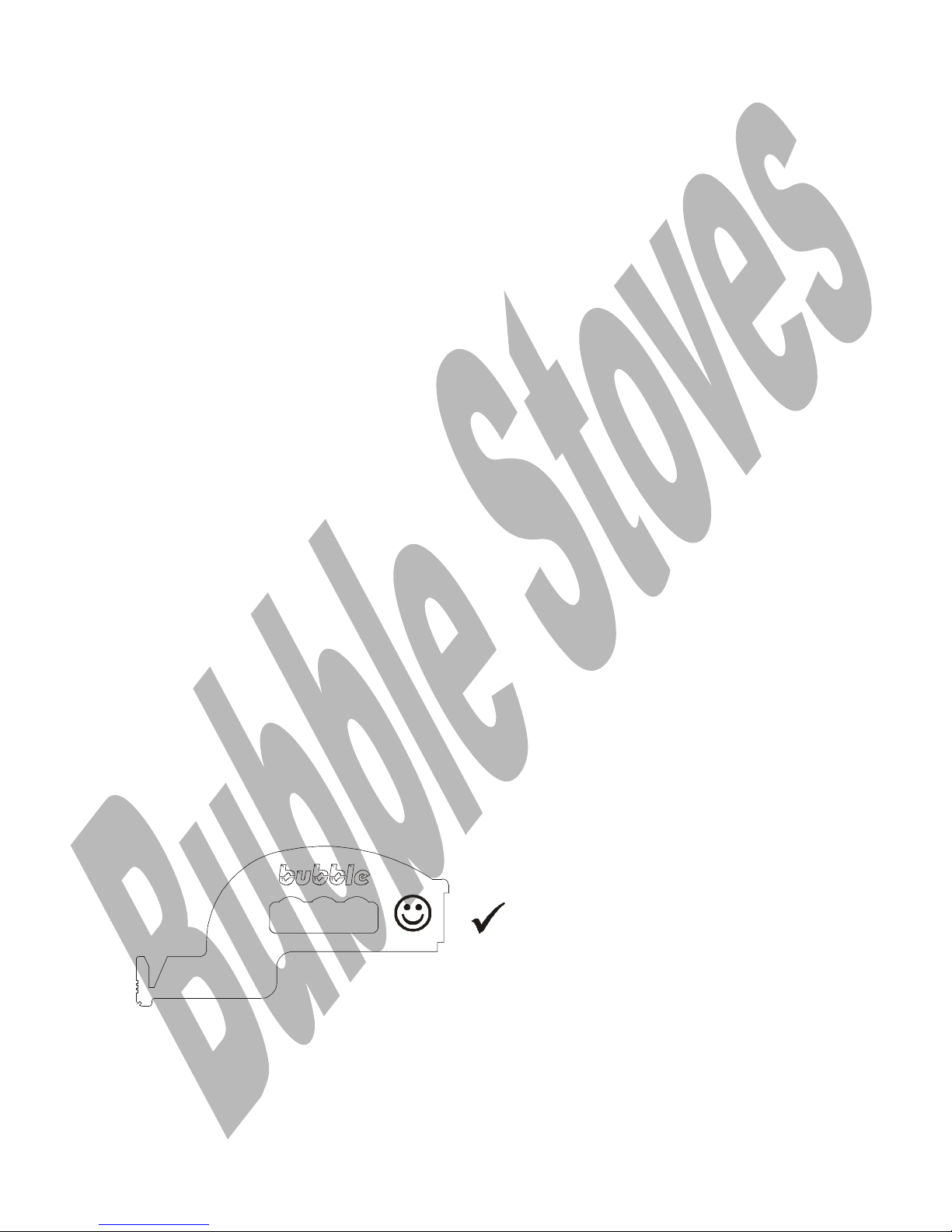
We have a cleaning tool, which can be useful if the pot is not too heavily carboned,
otherwise a small bent scraper has to be fabricated.
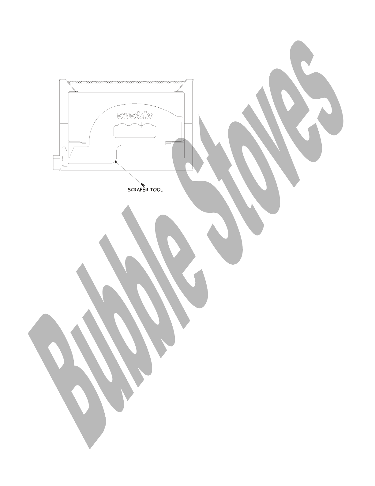
BB1, BB2 and BELFORT SCRAPER TOOL
Page 9
9
BB1,BB2 and BELFORT, SCRAPER TOOL IN POT.
Use a toffee hammer to tap the scrapping tool.
(Use a mirror on a stick to view the carbon in the annulus.)
4. Clean the catalysers with a brush
5. Clean the flame ring with a brus h
6. Clean the stove or boiler internals with a soft brush
(If there is a thick coating of soot or scale on the stove it may be necessary to use a
scraper tool to remove it)
7. Check that the chimney is clean.
8. Check that your oil supply tank is not water contami nated by flushing oil through the
valve, into a settlement jar.
9. Clean or change all oil filters and water traps if fitted.
10. If applicable- Remove the door and door glass and thoroughly clean in warm soapy
water.
11. If applicable- check all door seals.
22--33 R
R
EEMMOOVVEE
D
D
RRAAIINN AANNDD
C
C
LLEEAANN TTHHEE
O
O
IILL
C
C
OONNTTRROOLL
V
V
AALLVVE
E
12. Drain the oil control valve using the drain screw.
(See Toby valve booklet.)
13. Remove and clean the internal filter in the oil contr ol v alv e.
(See Toby valve booklet.)
14. Brush all dust from the stove.
15. Vac up, clean all brassware and repaint the stove.
Page 10
10
16. Rebuild in reverse order
22--44 C
C
HHEECCKK TTHHAATT OOIILL FFLLOOWWSS FFRREEEELLYY IINNTTOO TTHHEE PPOOT
T
..
22--55.. C
C
HHEECCKK FFOORR
G
G
OOOODD
I
I
GGNNIITTIIOONN
Test fire the appliance to make sure that it lights easily, make sure that the low and high
firing rates are correct.
22--66 A
A
DDJJUUSSTT TTHHEE HHIIGGHH AANNDD LLOOWW FFIIRRIINNGG RRAATTE
E
..
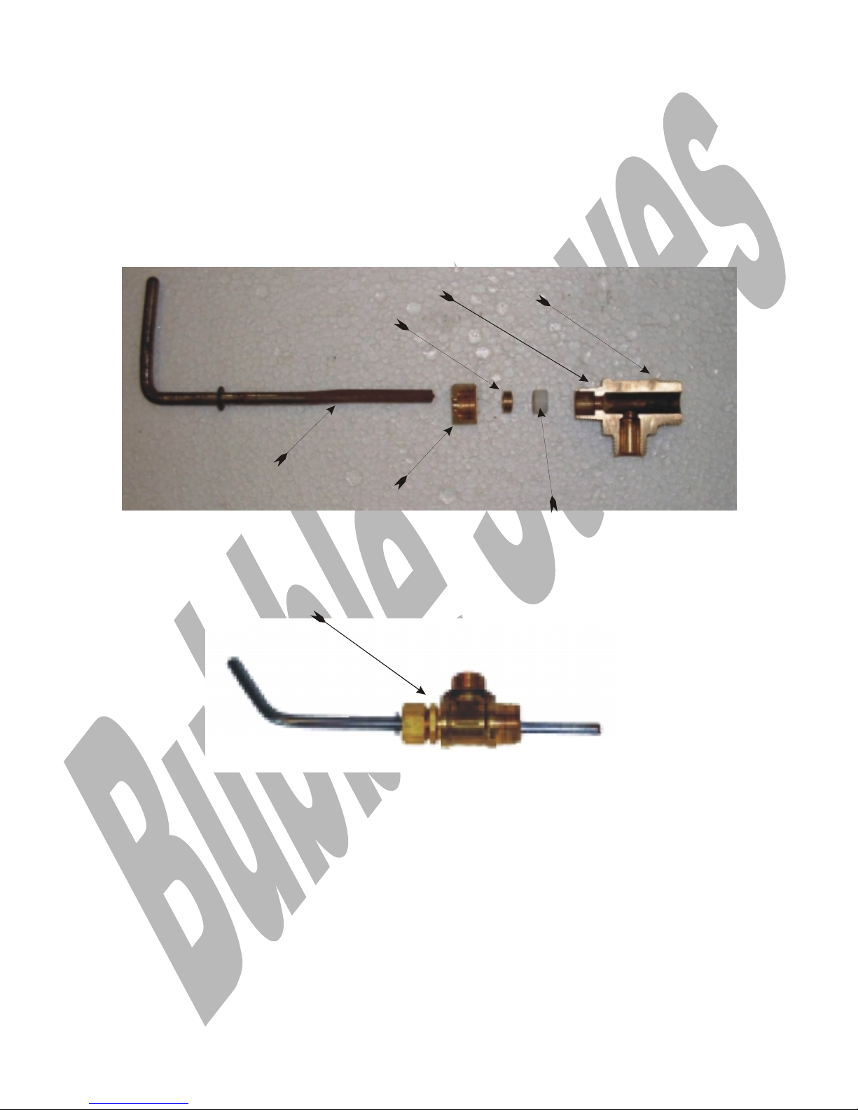
Descaling Device fig 1
Cranked Descaling Lever
Descaler Body
Compression Seal
Compresion Nut
Compression Olive
Slim Back Nut
Slim Ba ck Nut (not sh ow n )
33.. A
A
DDJJUUSSTT
D
D
EESSCCAALLIINNGG
D
D
EEVVIICCEE
F
F
IIGG
11
Every 12 Weeks
The descaling device is screwed directly into the vaporising pot and needs to be
dismantled adjusted and cleaned on a regular basis.
When the low fire flow rate is set on a new and clean pot there is no resistance to the
flow of oil.
During normal use carbon will build up around the inner diameter of the descali ng dev i ce.
This build up will act as a resistor to the flow of oil and the low firing rate will gradually
diminish until there is insufficient oil flow to support low fire, blue flame combustion.
Page 11

11
If the descaling lever does not rotate in a nice arc to properly clean all around the outer
edge of the outlet, it could be possible that the initial setting of the low firing rate will
have to be re-adjusted.
The descaling device comprises of a cast brass descaler body into which is fitted a
cranked descaling lever sealed via a compression nut, a small compression olive and a small
circular compression seal.
(When correctly adjusted, there should be a slight resistance to turning; if it is loose the
compression nut must be tightened slightly to keep an oil tight seal.)
Note the small compression olive has an internal cone shape at one end designed to
press on to the compression seal.
Oil enters the tee piece from a feed pipe connected directly to the outlet of the oil
control valve.
Oil is fed to the pot from the valve, throu g h the i nterconnecting feed pipe and into the
pot through the descaling device.
During normal running carbon deposits will build up in the bottom of the pot at the ou tlet
side of the descaling device, and in the descaling device.
To keep the oil flowing fr eely i n to the pot the outlet mu s t be de-scaled regularly and so to
do this it is necessary operate the descaling lever by turning it completely two or three
times, as you are rotating gently pull it out about 6mm (1/4") and then push it back to its
start position.
The descaling lever is cranked at one end to allow the flattened end to describe a larger
diameter arc, thus scraping any carbon deposits off the outlet diameter.
There are occasions where stoves are run under high flue vacuum conditions where
carbon deposits can only be removed from within the tee piece by physically removing
it completely from the pot, to allow access for descaling.
44.. C
C
LLEEAANN TTHHEE OOIILL FFEEEEDD
P
P
IIPPE
E
2. Remove and clean out the oil supply pipe from the oil control va lv e to the descali n g
device.
55.. C
C
HHEECCKK TTHHAATT TTHHEE
O
O
IILL
F
F
LLOOWWSS
F
F
RREEEELLYY IINNTTOO TTHHEE
P
P
OOT
T
After servicing carry out a visual check to make sure that the oil is flowing freely into
the pot.
1. Remove all the internals from the pot.
2. Turn the oil on to mini and look into the pot to make sur e that the oi l i s f lowing freely.
3. Remove any excess oil and leave the pot dry.
66.. C
C
HHEECCKK FFOORR
G
G
OOOODD
I
I
GGNNIITTIIOONN
Test fire the appliance to make sure that it lights easily, make sure that the low and high
firing rates are correct.
Page 12

12
77.. C
C
HHEECCKK TTHHEE
L
L
OOWW AANNDD HHIIGGHH
F
F
IIRREE
F
F
LLAAMMEE
BBBB11,, BBBB22
AANNDD
BBEELLFFOORRTT
There are two types of v alv e, which could be fitted to the stove.
Access to the low fire adjustment is different; make sure you know which valve you are
working on.
On the OCI ships valve the plastic drive knob has to be removed to gain access to the low
fire screw.
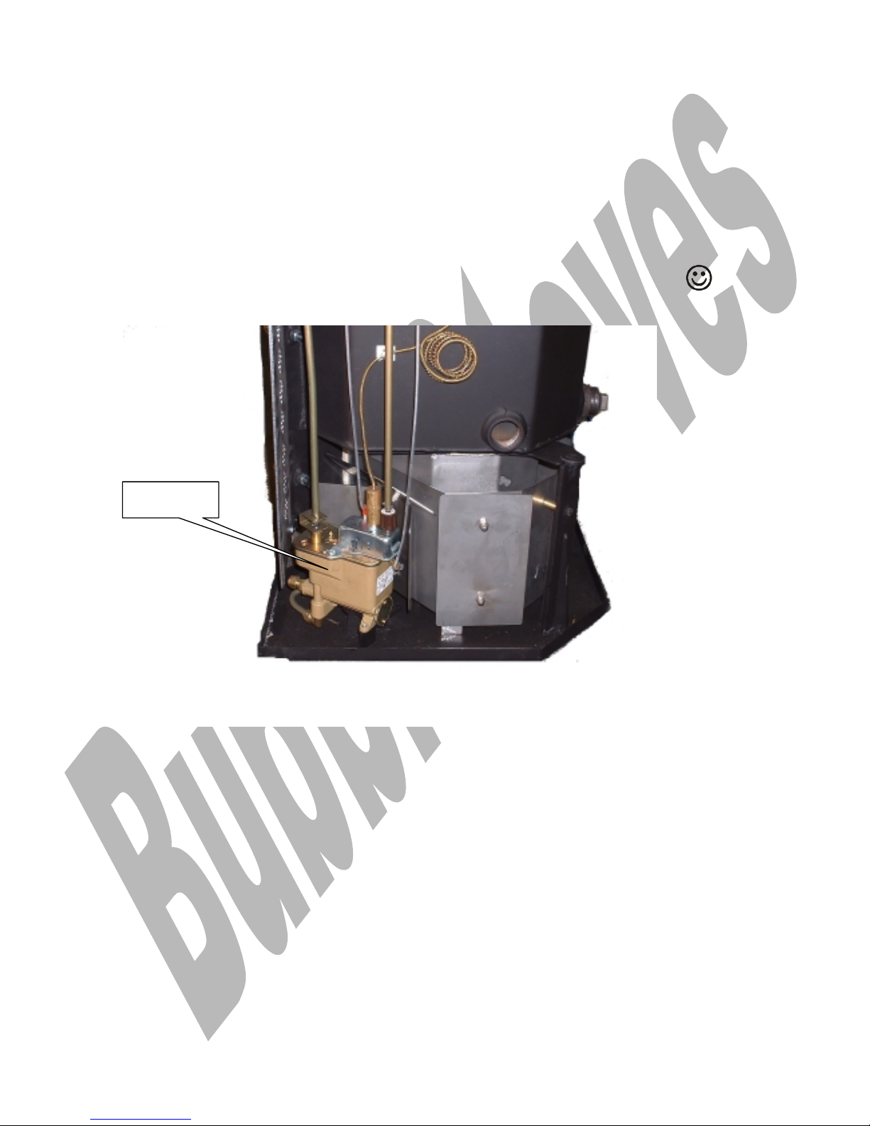
On the Toby valve the low fire screw is clearly visible as per TOBY MANUAL FIG 2
1. It is advisable to have a flue vacuum gauge available before carrying out this procedure.
2. When the burner has established combustion turn it up to half output. (Setting 3 on the
fuel flow control knob) and let i t settle down into blue flame combustion.
3. Allow at least half an hour for the chimney to warm up and the burner to stabilize
before making any adjustments to the high or low fire screws.
4. Zero the vacuum gauge and inser t the probe. (Each different stove has a vacuum test
point, for location refer to the stov e techni cal detai ls .)
5. The vacuum should read between (.02” - .03") minimum or (.05” - .06”) max
(If you can’t get a reading investigate the cause by checking out the flue system and
smoke bomb if required.)
6. Turn the stove down onto minimum f i ring rate and let the flame stabilise.
7. When the flame is stable the low fire catalyser should be glowing dull red in the bottom
of the pot with wispy blue flames flicking in to the glowing edge of it.
8. If the flame drops out of blue flame combustion and falls into a dirty rolling yellow
flame and the lower catalyser is not dull r ed then the low fire setting will need to be
increased until it can support the required blue flame combustion.
Note to increase the low fire fuel flow, screw in on OCI valve and out on Toby valve.
9. When you are happy with the low fir e comb u s ti on, s et the hig h f i re as follows
10. Turn the oil flow knob up to setting 4; let the flame stabilise, and look at it, if it is
stable and blue, turn it up slowly using the control knob, letting it stabilise after each
movement.
11. If the flame starts to go yellow and progresses into long yellow flame combustion, it is
running fuel rich and the high f i re screw needs adjusting to reduce the flow of oi l. (Screw
in for both types of valve)
12. Do not make any attempt to adjust the high fire screw, u nti l you hav e b rought the
flame back into blue flame combustion.
To do this turn the fuel flow down until the yellow flames drop back into blue f lame
combustion.
Page 13
13
13. Adjust the high fire screw by half a turn in and try turning the fuel flow up, if it is still
fuel rich rep eat the process until the hire fire flame is running blue with fli cks of ye llow in
the tips.
14. When you think that you have the flame as you want it leave it running for ten minutes
to see if it is stable.
15. Adjustment of the flame will not be possible unless our instructions on chimneys and
flue vacuum are followed.
88.. C
C
HHEECCKK TTHHEE
L
L
OOWW AANNDD HHIIGGHH
F
F
IIRREE
F
F
LLAAMMEE
((CCOORRNNEERR AANNDD RROOUUNNDD SSTTOOVVEE))
There are two types of v alv e, which could be fitted to the stove.
Access to the low fire adjustment is different; make sure you know which valve you are
working on.
On the OCI ships valve the plastic drive knob has to be removed to gain access to the low
fire screw.
On the Toby valve the low fire screw is clearly visible as per TOBY MANUAL FIG 2
It is advisable to have a flue vacuum gauge available before carrying out this procedure.
The Toby valve has been flow rated before leaving the factory and it should not need
adjusting, if it does it is necessary to remove th e plast ic drive c o ve r (OC I VALVE) which is
held in place by a single fastener in the side face of the knob.
Once the knob has been removed the low fire adjusting screw is clearly visible.
When the burner has establi s hed g ood b lu e f lame combustion turn it up to half output.
Toby Valve
Page 14

14
(Setting 3 on the fuel flow control knob) and let it stabilize.
Allow at least half an hour for the chimney to warm up thoroughly before making any
adjustments to the high or low fire screws.
Turn the stove down onto minimum firing rate and let it stabilize.
After stabilization the catalyser should be glowing dull red with wispy blue flames
suspended off the top of it, just level w i th the top of the pot.
If the flame falls into a dirty rolling yellow flame then the low fire w ill need to be
increased until it can support the required blue flame combustion.
When you are happy with the low fire, set the high fire.
Turn the oil flow knob up to setting 4, let the flame stabilize, and look at it, if it is stable
and blue, turn it up slowly using the control knob, letting it stabilize after each movement,
if the flame starts to go yellow with long flame combustion, it is running fuel rich and the
high fire screw needs adjusting to reduce the flow of oil.
Before adjusting the high fire screw, turn the flame down and let it stabilize in blue flame
combustion, adjust the high fire screw by half a turn at a time and try turning the f u el
flow up, if it is still fuel rich repeat the process until the hire fire flame is running blue
with flicks of yellow i n the tips.
Note there is not a large differ ence b etween the high and low fire.
99.. C
C
HHEECCKK
A
A
CCTTIIOONN
O
O
FF
OOPPEERRAATTIINNGG AANNDD S
S
AAFFEETTYY
T
T
HHEERRMMOOSSTTAATTSS
1. Stoves with large boilers also have an automatic water temperature contr ol thermostat
and an automatic safety stat device. (Detailed information is provided in the Toby valve
booklet.)
(Assuming that the oil flow control knob is set to 5 or 6)
2. If the stove is operated with the ther mos tat controls set to maximum it will run on full
flame, until it achieves the target water temperature and then drop the flame onto mini,
from there on it will automatically modu late the f lame f rom high to low in line with the
heating load demand.
3. To check the action of the control stat proceed as follows -:
3-1 Turn the central heating pump off.
3-2 Fix a pipe thermometer to the hot w ater outlet.
3-3 Turn the appliance up to full fire (Setting 6 on the oil valve)
3-4 Turn the thermostat up to f ull ou tpu t ( f u lly anti clockwise)
3-5 Watch the water temperatur e thermometer and as the water temperature comes up
to 70 deg C the valve should drop the stove onto low f i re.
3-6 To check the action of the safety stat allow the water temperature to come up to 90
deg C and the safety stat should shut the oil flow off.
Page 15

15
NOTE 1.
It will not be possible to reset the stat until the water temperature has dropped.
NOTE 2.
Details on adjustment of the operating and safety stat can be found in the appliance
installation details, or in the commissioning routine.
1100.. C
C
LLEEAANN TTHHEE
S
S
TTOOVVEE
I
I
NNTTEERRNNAALLSS
Every 12 months
1. To clean the stove internally use a soft brush and brush away any dust or comb ustion
debris into a vacuum cleaner hose.
1111.. C
C
LLEEAANN TTHHEE
S
S
TTOOVVEE
E
E
XXTTEERRNNAALLLLYY
As Required
1. To clean the stove externally, let it go out and simply brush and v ac away any dust with a
very soft brush.
1122.. C
C
HHEECCKK TTHHEE
D
D
OOOORR
S
S
EEAALLSS
The seal is designed to stop the ingress of air into the combustion chamber and as such
must form a good seal with the fr ont of the s tov e all around the door opening.
2. Check via visual examination that it is forming a good seal with the stove body.
3. The seal is fastened into its socket via high temperature ceramic adhesive available
from our spares department.
The ends of the ceramic rope are terminated with high temperature adhesive tape.
4. When replacing the door seal make sure that the socket into which the seal is fitted is
cleaned out prior to the application of new adhesive.
1133.. C
C
LLEEAANN TTHHEE
D
D
OOOORR
G
G
LLAASSSS
If applicable
1. The door glass will require light cleaning occasionally and the frequency of cleaning will
depending upon how the stove is used.
2. Where stoves are ignited each day then the glass may s oot up as the lig h ti ng process
may generate a little soot until the stove has settled down into blue flame combustion.
3. Where stoves are running continu ou s ly then the g las s will need cleaning less frequently.
4. When cleaning is required you will need to let the stove go out and completely cool down.
5. To clean the glass use a soft clothe and dampen it with vineg ar or a proprietary stove
glass cleaner.
6. Rub the glass gently in a vertical direction, do not rub the glass with horizontal motion
otherwise the glass strips will be disturbed and dirt will be forced in between them.
Page 16

16
7. After cleaning the glass, wipe it dry and make sure that the glass strips have not been
dislodged.
Note: the glass strips have to fit together w i th no g aps .
NOTE-: see individual stove spare parts list for replacement parts.
1144.. A
A
DDJJUUSSTT TTHHEE
D
D
OOOORR
F
F
AASSTTEENNIINNG
G
..
Every 12 months or as required
1. The door fastener may need adjusting occasionally to ensure that the airtight fit is
maintained.
1155.. S
S
TTOOVVEESS WWIITTHH
B
B
AARROOMMEETTRRIICC
D
D
AAMMPPEERRSS
–– C
C
HHEECCKK
F
F
UUNNCCTTIIOONN
Note Barometric dampers attempt to control excess f lu e v acu u m b y s pi lli ng ai r into the
flue thus reducing the vacuum applied to the bu rner.
Every Year
Applies to BB1 – BB2 and Belfort
1. The barometric damper must be cleaned to remove any build up of dust and checked to
make sure that it swings freely and is correctly adjusted.
2. The damper will only swing open under conditions where the maximum chimney vacuum is
exceeded, normally this will be anything over .05”-.06” W.G.
3. At any vacuum below this figure the damper should be in a closed position.
Apply WD40 to the spindle tips.
1166.. S
S
TTOOVVEESS WWIITTHH
C
C
OOMMBBUUSSTTIIOONN
A
A
IIRR
R
R
EESSTTRRIICCTTOORRSS
–– C
C
HHEECCKK
F
F
UUNNCCTTIIOONN
Note Combustion air restr i ctors attempt to control chimney vacuum by restricting the
flow of air into the bu rner.
Every Year
Applies to Corner Bubble and Round Bubble
1. The combustion air restrictor or restrictors should be carefully cleaned.
Check that it swings freely.
Apply WD40 to the spindle tips.
1177.. C
C
HHEECCKK IIFF TTHHEE
H
H
OOLLEESS IINN TTHHEE
P
P
OOTT AARREE
F
F
RREEEE FFRROOMM
O
O
BBSSTTRRUUCCTTIIOONNS
S
Every Year
1. Each year the holes in the outer surface of the pot s h ou ld b e checked to make sure that
they are not blocked,
2. Because of the running temperature of the pot i t i s u nli kely that they will be blocked
with hair or dust, however if the burner has been running sooty, it is possible that there
could be some carboning or rust build up particularly around the bottom of the pot.
Page 17

17
1188.. C
C
HHEECCKK TTHHEE CCOOAALL KKIIT
T
Every 6 months
The coal kit system is designed so that it can be quickly and easily removed in its entirety.
2. Hold the front decorative fret and li f t ou t the complete ki t.
2a. Place the kit on a dustsheet and carefully remove the coals, which are located on the
coal support bars.
3. Examine-:
The coal support bars.
The cross ties.
The coals.
Note:
Distortion will occur on the bars and ties, if it is excessive, replace as a service item.
See the relevant parts list for identification of spare parts.
4. Care must be taken when positioning the coals on the spike follow the coal layout
illustration for the relevant kit.
1199.. S
S
TTOOVVEESS WWIITTHH
E
E
LLEECCTTRRIICC
I
I
GGNNIITTIIOON
N
Every 6 Months
Remove and clean the plug
Refit and test the function
1. The spark plug should be carefully removed and cleaned.
2. Take care when refitting the plug.
3. Make sure that the tip of the metal wick ju s t tou ches the bottom of the pot.
4. Make sure that the supply leads do not foul or fret on thin metal heat shields.
5. Make sure that the leads are not taped up together as they need to hav e an ai r gap
around them for cooling purpos es .
6. If the plug does not form a good seal with the plug port, air will be drawn into the pot
and consequently upset the combustion process
7. This will manifest itself in the form of intensive and heavy c arbon build up in th e bottom
of the pot reaching up behind the inner s kin of the pot.
2200.. V
V
EENNTTIILLAATTIIOON
N
Check Ventilation Area
1. To accommodate the combustion air requi rements of the appliance
Check that adequate free air ventilation is provided.
Page 18
18
(550 mm sq per kW of appliance rating.)
2211.. O
O
IILL
T
T
AANNK
K
,, V
V
AALLVVEE
F
F
IILLTTEERRSS AANNDD
L
L
IINNEE
As required, carry out an oil line inspection.
Clean or change the oil tank filter every year or as required, we have found that paper
filter cartridges can ab s orb moisture and freeze in cold weather creati ng oi l f low
problems. To check for this condition check oil flows out of the inlet vent but not the
outlet vent.
Check that the oil tank is not contaminated with water or dirt.
Check that the isolation valve is working correctly and easily accessible
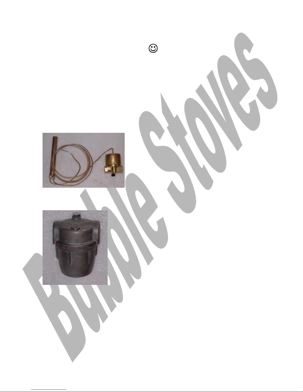
To check the action of the KBB fire valve. Carefu lly heat u p the s ens i ng b u lb to a maximum
temperature of 70 deg c, and make sure that the v alv e s h u ts of f .
Allow the bulb to cool down and then r es et it ready for use.
Check that the fuel filter not contaminated with water or dirt.
Clean or change the oil tank filter every year or as required, we have found that paper
filter cartridges can ab s orb moisture and freeze in cold weather creati ng oi l f low
problems. To check for this condition check oil flows out of the filter inlet vent bu t not
the filter outlet vent.
The filter illustrated has a washable nylon filter, which does not suffer from moisture
absorbance problems.
Page 19

19
2222.. F
F
LLUUEE
Check flue type and suitability, as required
Flue Terminal Compliance Check, as required
Fire Guard Compliance Check, as required
Make sure that the flue system is airtight.
Check the flue vacuum using an appropr i ate manometer. Flue should pull between .02” and
.06” W.G.
Page 20

20
44 F
F
AAUULLTT
F
F
IINNDDIINNGG
To assist with servicing and fault finding we categorise problems under the
headings listed.
11.. F
F
UUEELL
S
S
UUPPPPLLYY
P
P
RROOBBLLEEMMS
S
(See Pre Amble notes)
1. Fuel contamination problems
2. Fuel type and quality problems
3. Fuel feed problems
22.. A
A
IIRR
S
S
UUPPPPLLYY
P
P
RROOBBLLEEMMS
S
Air is drawn i nto the burner by the action of the chimney.
THE POWER, (suck or vacuum the chimney can develop) depends upon the
following-:
THE HEIGHT.
THE DIAMETER .
THE TEMPERA TURE OF THE GASSES IN IT.
THE RESISTANCE OF THE INNER SURFACE OF THE FL U E P I P E OR P IP ES .
On a boat all the above elements are in short s u pply .
Normally, we have to deal with low flues which are small in diameter and
generally not very well insulated, coupled with all these pr ob lems we have an
other one, which is that the boat mo ve s across co nst ant ly c hanging surroundings,
through locks, into headwinds and crosswinds, all creating major opportunity for
down draughting to occur.
Any bend in any part of the chimney or roughness on the internal chimney wall
will slow down the velocity of rising gases and reduce the effectiveness of the
chimney.
Any slight reduction in the flue gas temperature will reduce the chimney vacuum
or pull, hence when the stove is slowed down for all night burning, as the flue gas
cools down the chimney vacuum reduces and as the chimney vacuum drops, the
stove may well start to burn sooty.
This problem is highlighted even more during very cold weather when the
chimney can cool down even faster.
THE CHIMNEY RULES.
Always use a top outlet for flue pipe take off.
Never put any bends in the flue. (To maintain a concentric fit, we will allow a
slight kick off the stove and a similar kick into the deck flange).
Page 21

21
Always try to get the stove as low as possible in the boat, this will allow
installation of maximum length flue pipe.
Always have two double walled, above deck extensions, short for cruising and
long (28inch minimum) for mooring. Insulated extensions are a thing of the
future but it is possible to fill the space using a vermiculite and cement mix
sealed off with flexible fire putty.
Fit a rotary swing i ng cowl to each extension or make one interchangeable.
Clean or have the chimney cleaned regularly. (Frequency depends upon type of
fuel and length of time used).
Loss of chimney vacuum can also be caused by-:
Faulty Stove seals.
Door seals, Glass seals, Pot to closure plate seal, damaged door glass.
Bad deck flange fitting.
33.. C
C
OOMMMMIISSSSIIOONNIINNGG
P
P
RROOBBLLEEMMS
S
(See Pre Amble notes)
Commissioning, or lack of it, is the biggest single problem asso c iate d with alleged
faults on Bubble stoves.
44.. P
P
LLUUMMBBIINNGG
C
C
IIRRCCUUIITT
D
D
EESSIIGGN
N
If the plumbing circuit is not of a suitable design, it will not be possible to carry
out the commissioning procedure as the burner may well shut down due to
overheating of the boiler .
Always check that water is flowing freely through the boiler.
If the oil valve safety stat shu ts the b u rner down, check the temperature of
the boiler outlet flow pipe.
55 B
B
UURRNNEERR
D
D
OOEESS
N
N
OOTT
L
L
IIGGHHTT
E
E
AASSIILLY
Y
1. Check the level of the bottom of the pot and make sure that the stove is
levelled so that the oil flows very slightly towards the ignition wick.
2. Check the chimney vacuum cold.
3. Check that all the seals in the stove are sound.
4. Check that the swinging dampers are not jammed open.
5. Check that the oil is flowing freely i nto the pot.
See Pre Amble notes.
66 S
S
TTOOVVEE
G
G
OOEESS
O
O
UUTT
W
W
HHEENN
T
T
HHEE
C
C
EENNTTRRAALL
H
H
EEAATTIINNGG
P
P
UUMMPP
I
I
SS
T
T
UURRNNEEDD
O
O
FFF
F
1. Generally this is caused by the action of the safety stat, which shuts off the
flow of oil to the appliance from the oi l control valve.
This will be observed via a tripped off oil valve.
Page 22

22
Re set the valve to re commission the oil supply.
Note each different valve has a different re setting procedure, which should be
detailed in the appliance manual.
2. To check this out, feel the trip lever to see if it has tripped off, if it has this
will confirm the cause.
3. Unwanted trip offs can be caused by one of the following-:
3-1. The flow of water to the heat leak rad is inadequate.
3-2. The size of the heat leak rad is inadequate.
3-3. The safety stat set point needs increasing.
3-4. The heat leak circuit has been inadver tently eli minated or reduced via the
turning off of the upstairs radiators, (as could be the case in summer time
running.)
77 F
F
LLUUEE
V
V
AACCUUUUM
M
1. The pot type burner is extremely sensitive to flue vacuum vari ati ons .
2. Good combustion will not be possible unless our instructions on chimneys and
flue vacuum are followed.
3. If the burner does not bur n with a blue flame, recheck the chimney vacuum
and oil flow rate.
4. If the burner does not run well check that the seals in the stove are good and
that there is no ingress of air into the appliance flue ways.
5. Check that the swinging damper is not jammed open. (BB1, Belfort and BB2
Stoves)
6. Check that the correct fuel oil is being u s ed.
7. Check the levels.
88 B
B
UURRNNEERR
Q
Q
UUIICCKKLLYY
C
C
AARRBBOONNSS
U
U
P
P
See Sec 2 Pre Amble
99 O
O
IILL
W
W
IILLLL NNOOTT
E
E
NNTTEERR TTHHEE
P
P
OOT
T
(See Pre Amble plus the f ollowing.
With each appliance a separate oil valve booklet is provided, make sure that you
have it to hand when carrying out thi s type of work.
NOTE.
On new installations, it is not unusual for an air bubble to restrict the flow of oil
through the metering stem in the oil control valve.
To cure this problem gently tap the valve with a plastic handled screwdriver or
agitate the oil in the float chamber to try and b reak the meniscus lock created
by the air bubble.
Page 23

23
Is there oil in the fuel tank?
Has the fire valve tri pped?
Has the isolation valve been accidentally turned off?
Is the oil turned on at the oil flow contr ol knob on the valve?
Has the level of the oil valve been distu rbed?
The oil level mark on the side of the oil control valve should be set at 20mm
from the bottom of the pot, check this out usi n g a rule or height gauge.
Is the oil feed pipe from the valve to the pot bl ocked? (Unlikely)
Clean or change the oil tank filter every y ear or as required.
We have received reports that paper filter cartridges can absorb moisture and
freeze in cold weather creati ng oi l f l ow problems.
To check for this condition check oil flows out of the inlet vent but not the
outlet vent.
1100 C
C
HHEECCKK FFOORR
O
O
IILL
L
L
EEAAKKS
S
1. Check that oil does not leak from the pot, valve, and descaling device or pipe
work.
1111 C
C
HHEECCKK TTHHAATT TTHHEE
O
O
IILL IISS IINN TTHHEE
C
C
OORRRREECCTT
P
P
LLAACCE
E
1. Make sure that when the oil first r u ns in to the pot, i t is not running away
from the oil inlet.
2. It should gather in a small pool around the oil inlet at the bottom of the
lighting tube, if it does not do s o, lev el the stov e u p u nti l i t does .
3. When you are happy that the oil pool is forming in the correct position, the
stove will light easily and not be prone to ignition flair ups.
1122 F
F
LLOOOODDEEDD
O
O
IILL
C
C
OONNTTRROOLL
V
V
AALLVVE
E
See “Oil Will Not Enter the Pot”.
1133 O
O
IILL
S
S
MMEELLLLS
S
1. Carry out a visual check on all joints for any leaks.
2. Check that the descaling lever packing gland nut is adjusted.
3. If there is a slight lingering smell with no obvious visual signs of a leak, this
will be attributable to the descali ng lev er packing gland nut requiring
adjustment or possibly a new seal.
1144 O
O
PPEERRAATTIINNGG
F
F
LLOOWW
R
R
AATTEES
S
See 3-3-5a
Page 24

24
1155 B
B
UURRNNEERR
F
F
LLAARREESS
U
U
PP
D
D
UURRIINNGG
I
I
GGNNIITTIIOON
N
If the burner flares u p du ring the ignition cycle, this is normally caused by
allowing too much fuel into the pot before the flame has had the time to come
up to establish at vaporis a ti on temperature.
The other cause of this is the b u rner being out of level and the incoming fuel
running away from the lighting port and forming a pool opposite the lighting port.
Oil entering the pot should form a pool at the bottom of the li g hti ng port tube.
1166 D
D
E
E
--F
F
LLOOOODDIINNGG AA
F
F
LLOOOODDEEDD
P
P
OOT
T
If the pot has become flooded with oil proceed as follows: -
1. Wear plastic gloves do not allow fuel oil to contact your skin, if it does wash
off immediately with soap and warm water.
2. You will need a plastic bag and a small sponge, remove the coal kit if
applicable, catalysers and ring to giv e clear access to the base of the pot.
Sponge out the fuel and squeeze the sponge into the plas ti c b ag , ( i t helps to
keep drips to a minimum if the bag is put inside the stove) when all the oil has
been sponged from the stove it will be safe to re assemble and re-ignite.
Note there are generally two reasons for flooding,
1. High winds have caused down drafting which has blown the burner out.
2. The appliance has run out of oil and the user has f i lled the oi l tank without
first turning the b u rner off.
DO NOT ATTEMPT TO BURN OFF A FLOODED POT
Never try to ignite a flooded pot, always de flood it as described in 4-15.
1177 R
R
AACCIINNG
G
1. The term racing is used to describe audible vibrations, generated by the flame
and caused by allowing excessive oil to build up in the bottom of the pot too
quickly during the ignition process.
2. Turn the oil flow off unti l the b u rner has settled down into a steady burn
rate.
3. Turn the fuel on again but don’t let the f lame g o ou t, otherwise the burner
MUST be allowed to cool down fully before a re ignition is attempted.
Page 25
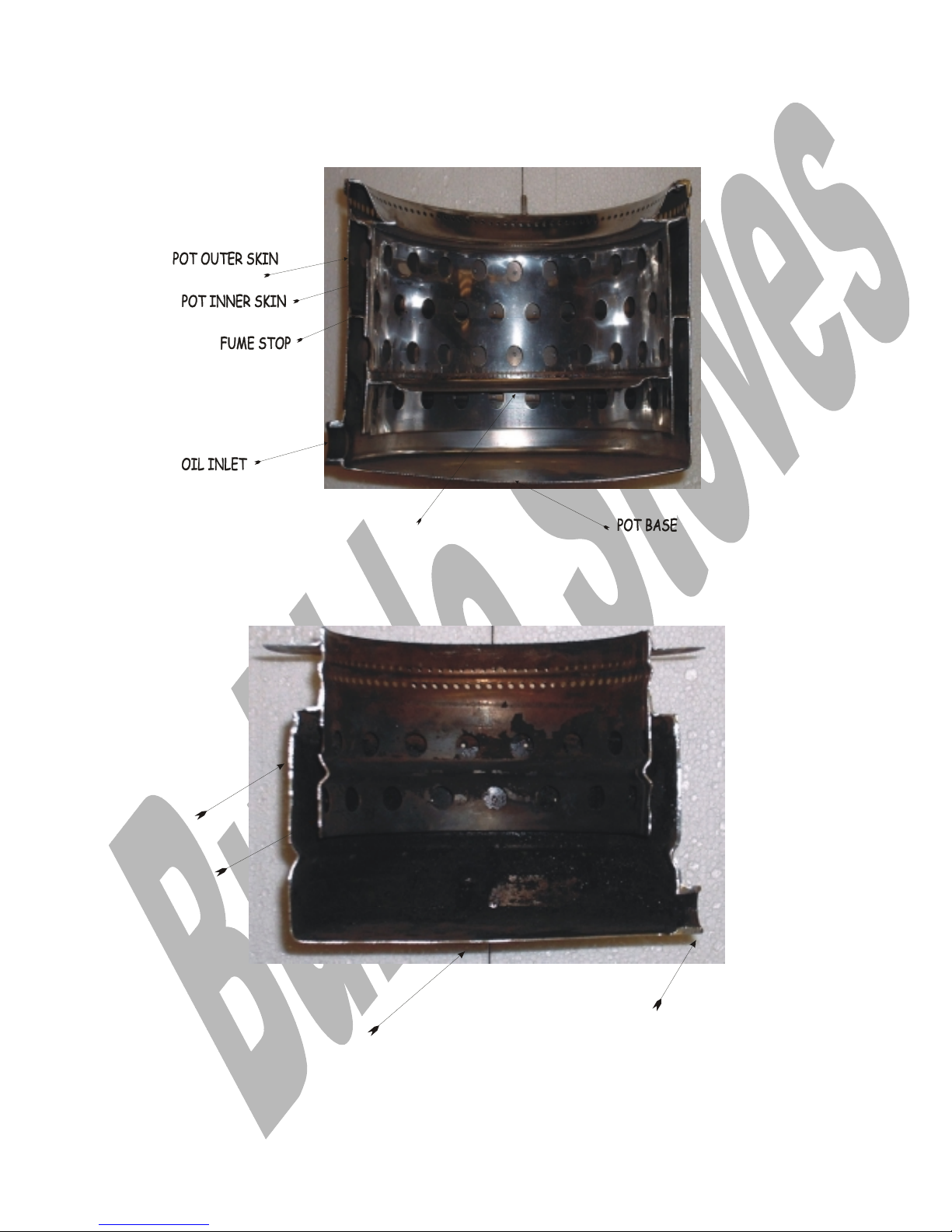
25
F
F
IIGGUURREES
S
F
F
IIGG
22 S
S
EECCTTIIOONN OOFF
B
B
UUBBBBLLEE
11 P
P
OOT
T
UPPER CATALYSER SUPPORT
F
F
IIGG
33 S
S
EECCTTIIOONN OOFF
C
C
OORRNNEERR AANNDD
R
R
OOUUNNDD
B
B
UUBBBBLLEE
P
P
OOT
T
POT BASE
OIL INLET
INNER SKIN
OUTER SKIN
Page 26

26
A
A
DDDDIITTIIOONNAALL
P
P
UUBBLLIICCAATTIIOONNS
S
I
I
NNSSTTAALLLLEERR IINNFFO
O
..
Bb1
Bb2
Corner Stove
Bubble PJ
U
U
SSEERR IINNFFO
O
..
Bb1
Bb2
Corner Stove
Bubble PJ 12/24 volt dc
Bubble PJ 12/24 volt dc
Bubble PJ 230 volt ac
P
P
AARRTTSS LLIISSTTS
S
Bb1
Bb2
Corner Stove
Bubble PJ 12/24 volt dc
Bubble PJ 230 volt ac
P
P
RRIICCEE
L
L
IISSTTS
S
Oil stoves
Marine Oil Stoves
Conversion Kits
Oil Spares Price List
O
O
TTHHEERR
I
I
NNFFO
O
..
Toby Valve Booklet
OCI Ships Valve Booklet
Deck Flange Info
Digital Time clock Info
Flexaflame and Pressure Jet Conversions.
Vaporising Pot Conversions
Gas free Cooking and Central Heating
Unvented heating system.
Water circulating pump leaflet.
© HARWORTH HEATING and BUBBLE PRODUCTS LTD 26-01-05
This publication may not be copied by any means, without written permission from the authors.
Page 27

27
Products made by Harworth Heating Ltd. are subject to continuous development and improvement and it is
consequently acknowledged that due to this process there may be some omissions and errors.
This publication is intended only to assist the reader in the maintenance of this product and therefore
Harworth Heating Ltd shall not be liable for any loss or damage whatsoever arising from the use of any
information, error or omission found in this publication.
Only approved personnel, WHO HAVE BEEN SUITABLY TRAINED,
must carry out maintenance on this product.
 Loading...