

Page 1
1
Mk 2 VAP. CONVERSION
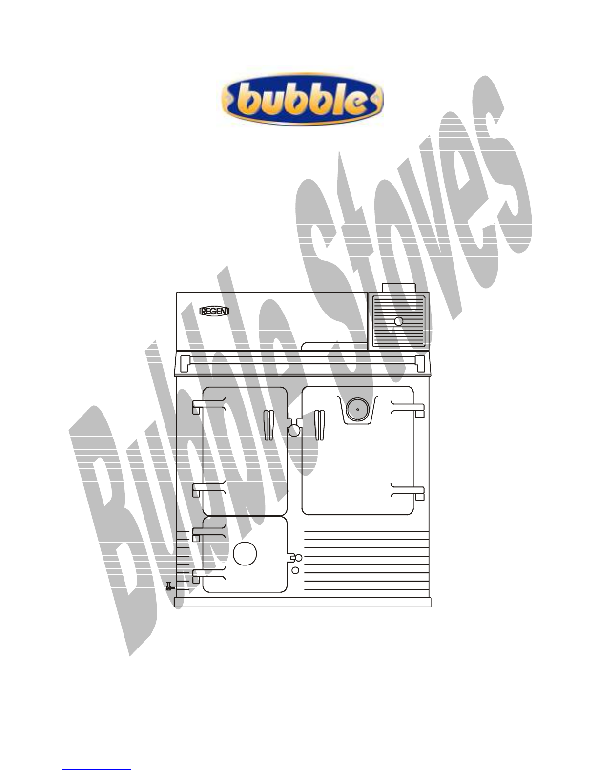
2 Rayburn Regent
27-09-03
installation information
http://www.oilstoves.co.uk/
Page 2

2
Page 3

3
Contents
1. Health and Safety.___________________________________________ 4
Control of Substances.__________________________________________ 4
2. Applicable Regulations. ________________________________________ 4
Building Regulations. ___________________________________________ 4
Electrical Regulation. ___________________________________________ 4
BS5410 Oil Fired Space Heaters. __________________________________ 4
BS5449 Central Heating. ________________________________________ 4
BS6461 Pts 1 & 2 1984. _________________________________________ 4
BS7566 Parts 1 to 4. ___________________________________________ 4
OFTEC Regulations. ____________________________________________ 4
3. How To Approach The Job. ____________________________________ 5
1 Customer. __________________________________________________ 5
2 Chimney.___________________________________________________ 5
3 Existing Heat Load.___________________________________________ 5
4 Oil Supply Line And Tank Location.________________________________ 5
5 Electrical. _________________________________________________ 5
6 Ventilation._________________________________________________ 5
4. Introduction.________________________________________________ 6
5. Chimney Problems. ___________________________________________ 6
1. Chimney Lining Sizes. _________________________________________ 6
2. Access For Chimney Cleaning. ___________________________________ 7
3. Chimney Terminations. ________________________________________ 7
4. Flue pipe.__________________________________________________ 7
6. Existing Heating System. ______________________________________ 7
7. Oil Feed And Storage. ________________________________________ 7
8. Electrical Requirements. ______________________________________ 8
9. Ventilation. _________________________________________________ 8
10. Regulations. _______________________________________________ 8
11. Fitting THE KIT. ___________________________________________ 9
Removing The Firebricks. ________________________________________ 9
Remove The Ash pan. __________________________________________ 10
Seal The Riddling Lever.________________________________________ 10
Vac The Debris Out. __________________________________________ 10
Check Firebricks._____________________________________________ 10
Page 4

4
Check The Hot Plate Seal. ______________________________________ 10
Remove The Flue Box Damper Plate. _______________________________ 10
Lock The Air Valve Open. _______________________________________ 10
Fitting The Boards And Pot. _____________________________________ 10
Fit The Oil Control Valve._______________________________________ 15
Fit the baffle kit. ____________________________________________ 16
12. Commissioning and Finishing off. _______________________________ 16
Before Test Firing The Burner. __________________________________ 16
To Test Fire.________________________________________________ 17
Low Fire Adjustment.__________________________________________ 18
High Fire Adjustment. _________________________________________ 18
Shutting Down. ______________________________________________ 18
Controls. ___________________________________________________ 19
13. Specifications. ____________________________________________ 19
14. Fault Finding. _____________________________________________ 19
1. Racing. _________________________________________________ 19
2. Flue Vacuum. _____________________________________________ 19
3. Burner Runs Sooty. ________________________________________ 19
4. Burner does not light easily.__________________________________ 20
5. Oil Will Not Enter The Pot. __________________________________ 20
7. Operating Flow Rates. ______________________________________ 21
8. Oil Smells. ______________________________________________ 21
15. Servicing. ________________________________________________ 21
16. Packing List Major Assemblies. ________________________________ 21
Vap Board Kit. _______________________________________________ 21
17. Packing List Sub Assemblies. _________________________________ 21
18. Boards and Closure Plates ____________________________________ 23
19. Illustrations.______________________________________________ 24
Fig 19 Oil feed details._________________________________________ 24
Fig 20 Cooker Section. _________________________________________ 25
Fig 21 Chimney terminal details. __________________________________ 25
19. Optional Extras. ___________________________________________ 26
The Oven Stat. ______________________________________________ 26
Page 5

Page 6

4
H
EEAALLTTHH AANNDD
11.. H
C
OONNTTRROOLL OOFF
C
S
S
S
UUBBSSTTAANNCCEES
S
AAFFEETTY
S
..
E
LLEECCTTRRIICCAALL
Y
..
E
R
EEGGUULLAATTIIOON
R
N
..
British IEEE wiring regulations, latest
edition.
Take great care when handling
materials such as insulation boards,
glass fibre ropes, ceramic wool,
artificial fuel, kerosene and diesel oil,
they are all irritants and suitable
protective clothing such as disposable
gloves dust masks and protective
goggles should be worn.
Wash off thoroughly after handling
any of these materials.
Carefully dispose of redundant or
surplus materials and always vac up
after service or installation work.
A
22.. A
PPPPLLIICCAABBLLEE
R
EEGGUULLAATTIIOONNS
R
S
..
The installation of oil fired BUBBLE ©
equipment must be carried out by a
technically competent person, who is
experienced in both solid fuel and oil
fired installation.
Codes of practice which apply in the
UK are -:
BBSS55441100 O
IILL
IIRREEDD
F
S
PPAACCEE
S
H
EEAATTEERRS
H
S
..
O
F
Installation of oil fired space heating
and hot water supply Part 1, boilers of
rated output not exceeding 44kW
BBSS44554433 C
C
HHIIMMNNEEYY
S
PPEECCIIFFIICCAATTIIOONNS
S
S
.
.
Specification for chimney for oil fired
appliances. Part3.
BBSS55444499 C
C
EENNTTRRAALL
H
EEAATTIINNG
H
G
.
.
Central heating for domestic premises
Part 1 Forced circulation hot water
systems.
BBSS 55660011 BBSS88330033.
P
BBSS66446611 P
BBSS77556666 P
TTSS
P
AARRTTSS
.
11 && 22 11998844..
TTOO
11
44..
The competent person must be
capable of installing, commissioning
and servicing to the current
requirements of the relevant local
building and other statutory
regulations.
B
UUIILLDDIINNGG
B
R
EEGGUULLAATTIIOONNS
R
S
..
In England and Wales these are J 1-23 Provision for introduction of air
supply and discharge of products of
combustion. Provision for protection
against fire and heat.
In Scotland Part F sec 3.
In Northern Ireland Part L. In
Ireland Part J.
OOFFTTEECC R
R
EEGGUULLAATTIIOONNS
S
..
Installers must have successfully
completed OFTEC courses, OFT101
and OFT105.
Failure to comply with the relevant
requirements listed above can be
hazardous and could lead to
prosecution under the law.
If you have any difficulties please
phone our sales department on
PHONE 01302 742520. (3 lines.)
FAX 01302 750573
Email [email protected]
Web site www.oilstoves.co.uk
Page 7

5
When you visit your customer, take a
tick list and make sure you cover all
the points raised in this document.
As manufacturers of this product,
customer complaints are generally
made to us.
We will assist customers wherever we
can, to resolve any problems.
In general most problems are brought
about by failure to observe one or in
some cases many of the points raised
in this document.
These installation instructions will
form the basis of any faultfinding
assistance which we will give directly
to customers if installers are not
willing to help.
Make sure that you explain how the
appliance will be controlled.
Make sure that you explain about the
running costs.
Where new oil storage tanks are to be
installed make sure that they comply
with OFTEC rules and Building Regs
Make sure that the appliance hasn’t
been modified with the addition of a
larger, none standard boiler.
Make sure that customers are aware
that the appliance will need to be
cleaned out and serviced in line with
the schedule.
Here’s the tick list check out
11 C
C
UUSSTTOOMMEER
R
..
H
T
33.. H
OOWW
T
OO
A
A
PPPPRROOAACCHH
T
J
B
J
OOB
..
T
HHEE
Vaporising pot burners must have a
steady and continuous flue vacuum,
make sure that you check the terminal
position and ask questions about
previous or prior chimney problems, if
there is any doubt about the
suitability, height or terminal position
do not take the job on.
Make sure that the chimney is high
enough to generate a steady reliable
vacuum.
If you line the chimney make sure
that you explain to the customer
about the possibility of cross wind
noise ducting down the liner.
Make sure that you explain how the
conversion will work and how the
converted appliance will differ in
relation to being fuelled by solid fuel.
Go through all the points raised in the
first para and make sure that they
understand all of them.
22 C
C
HHIIMMNNEEY
Y
..
Performance (will it do the job) under
all conditions.
E
XXIISSTTIINNGG
33 E
H
H
EEAATT
L
L
OOAAD
D
..
Remember, if the appliance has a
boiler it was only originally designed
to heat a hot water cylinder and a
heat leak rad or towel rail, if the
appliance has a large boiler conversion
fitted you will not be able to fit one
of the kits as standard.
O
IILL
44 O
L
OOCCAATTIIOON
L
E
LLEECCTTRRIICCAAL
55 E
S
S
UUPPPPLLYY
N
..
L
L
L
..
IINNEE
A
A
NNDD
T
T
AANNKK
(Nearest Supply)
V
EENNTTIILLAATTIIOON
66 V
N
..
Page 8

6
I
NNTTRROODDUUCCTTIIOON
44.. I
N
..
The vaporising pot burner is designed
to run continuously.
It is extremely simple and all that the
user is required to do is operate the
oil flow control knob to achieve the
required oven or hot plate
temperature.
Upon starting from cold, the burner
should run until it gets the oven up to
a working temperature, when this
temperature is reached the oil flow is
set at the required number to match
the required oven temperature.
It is most important that all or any
existing chimney faults are
established and corrected before the
conversion work is carried out.
Hot and cold condition chimneys must
have a vacuum of not less than .02"
W.G. when COLD or more than .06"
W.G. when HOT.
If there are any problems such as: -
Occasional down draught.
Excessive up draughts.
Fume leaks.
Regular blockages.
The burner fires vertically and the
flame strikes the baffle which diverts
the flu gasses on to critical internal
components.
The three factors, which affect the
performance of the appliance, are -:
The fuel flow rate selected. (From 1 -
6)
The chimney vacuum.
The user.
It is not possible to use the oven
independently from the water heating.
C
55.. C
HHIIMMNNEEYY
P
RROOBBLLEEMMS
P
S
..
Before starting this installation you
must make absolutely sure that the
chimney does not have a history of
down draughting either intermittent
or permanent.
Before any work is carried out the
installer must check the existing
chimney vacuum whilst the appliance is
running at a normal operating
temperature.
If you are unsure about the condition
of the chimney, have it thoroughly
cleaned and checked by a suitably
qualified person.
If there is a history of excessive or
intermittent updraughting it may be
necessary to fit an extra automatic
flue draught regulator to allow for
extra control of these conditions.
This should be fitted as near as
possible to the appliance generally in
the open branch of a suitable tee.
Make sure that a suitably qualified
person carries out any remedial work.
The chimney should terminate 2 feet
above the ridge of the main or highest
roof, in compliance with relevant
legislation.
C
11.. C
HHIIMMNNEEYY
L
IINNIINNGG
L
S
S
IIZZEES
S
..
1. Use 5-inch dia linings
Page 9

7
On exposed chimneys built into end
gables backfill with loose fill
vermiculite to help prevent
condensation and improve the flue
draught stability.
A
22.. A
CCCCEESSSS
F
F
OORR
C
HHIIMMNNEEYY
C
C
LLEEAANNIINNG
C
G
..
Provision must be made to allow
adequate and easy access into the
chimney for cleaning purpose.
33.. C
C
HHIIMMNNEEYY
T
EERRMMIINNAATTIIOONNS
T
S
..
Do not fit gas cowls; rain cowls will
suffice, where there is no history of
down draughting.
If there is any history of down
draughting always fit a VEDETTE
ANTI DOWNDRAUGHT COWL.
It is most important that all or any
existing heating system faults,
(particularly on the plumbing side) be
identified and rectified before
conversion is carried out, it is the
responsibility of the installer to
assess this situation and make
adequate recommendations to the
customer.
Because this is an existing solid fuel
system it should have been installed
to BS5449 part one.
A double feed indirect hot water
storage cylinder to BS1556 part one,
should have been used and in order to
prevent the build up of scale and
corrosion a suitable inhibitor should
have been installed.
44.. F
F
LLUUEE PPIIPPE
E
..
The flue pipe used must not be less
than 5" diameter and must comply to
one of the following -:
Acid resistant vitreous enamelled flue
pipe to BS 1344 Part 2.
Stainless steel to BS1449 Part 2.
Cast iron to BS41.
E
66.. E
XXIISSTTIINNGG
H
EEAATTIINNGG
H
S
S
M
YYSSTTEEM
..
If there is excess load (more than
10,000 B.T.U.s to water the burner
will struggle to keep up with the
demand.
All pipe work in the primary circuit
must be 28 mm diameter and the pipe
work must be installed to provide a
suitable heat leak source (10,000
BTU, s.) and adequate gravity
circulation.
Do not convert to pressurised
systems, only open vented are
suitable.
Make sure that old boilers are not
blocked or heavily calcified.
Original Rayburn boilers can be
removed and inspected via the de
sludging access panel on the rear of
the boiler
O
F
A
77.. O
IILL
EEEEDD
F
A
NNDD
S
TTOORRAAGGE
S
E
..
NOTE
Installation of all oil feed pipe work
and storage equipment should be in
line with -:
Page 10

8
OFTEC requirements book T3 July
1995 rev.7.95.
(This is a statutory safety
requirement of the building regs.)
28 Second Commercial Kerosene to
BS2869 Part 2: 1988 Class C2 or 35
second gas oil BS2869 class D is
suitable for use with this burner
system but different oil control
valves will be needed.
Steel oil storage tanks to BS799 Part
5, if there is any doubt consult the
manufacturer.
Plastic oil storage tanks with B.B.A.
approval.
Minimum size storage tank should be
250 gals.
The burner can be supplied with oil via
gravity or pumped oil feed system.
The burner must not be installed on a
negative head oil supply system.
If a gravity system is used the base
of the tank must not be less than half
a metre or more than three metres
above the burner.
A 100-micron filter must be fitted
and the minimum fuel line diameter is
8 mm but this is dependant upon the
length of run.
Two remote acting fire valves such as
a Teddington KBB C 150 deg F with
suitable length capillary must be
fitted.
One at low level and one at high level.
The low-level phial bulb being mounted
near to the appliance.
There must also be a stop valve fitted
by the side of the appliance in a
conveniently accessible place.
E
88.. E
The converted cooker must be
earthed.
A neon-fused switch must service any
supplies taken to the cooker with a 3amp fuse fitted.
When the appliance is not in use the
electrical supply must be isolated.
99.. V
Air Supply To The Burner
It is most essential that a permanent
free air supply be established, as the
burner cannot function correctly
without it.
Provision for an adequate FREE air
supply in to the room where the
appliance is fitted is required.
This will take the form of a purpose
designed, NON hit or miss, air vent of
30.5 sq cm cross sectional area.
If an extractor fan is fitted in the
same room as the appliance then
provision for extra compensatory air
must also be made.
(This is a statutory safety
requirement of the building regs.)
1100.. R
LLEECCTTRRIICCAALL
V
EENNTTIILLAATTIIOON
R
EEGGUULLAATTIIOONNS
R
EEQQUUIIRREEMMEENNTTS
R
N
..
S
..
S
..
Both valve bodies must be fitted at
the point where the fuel line enters
the property.
After CONVERSION, the completed
system must comply with the current
requirements of the relevant local
building regulations,
Page 11
9
In England and Wales these are J 1-23 Provision for introduction of air
supply and discharge of products of
combustion.
Provision for protection against fire
and heat.
In Scotland Part F sec 3. In Northern
Ireland Part L.
In Ireland Part J.
British IEEE wiring regulations, latest
edition.
Codes of practice which apply in the
UK are -:
BS5410, installation of oil fired space
heating and hot water supply Part 1,
boilers of rated output not exceeding
44KW
R
EEMMOOVVIINNGG
R
T
T
HHEE
F
F
IIRREEBBRRIICCKKS
S
..
Remove the thick front firebrick
beneath the fuel-loading door.
(This is a time consuming job, don't
rush and take care not to apply too
much pressure as the front casting of
the appliance is only thin and can be
easily broken.)
Remove the oven side bricks.
Remove the lower sham side brick and
this will then allow access to the cast
iron plate fitted over the riddling
grate, which can now be removed.
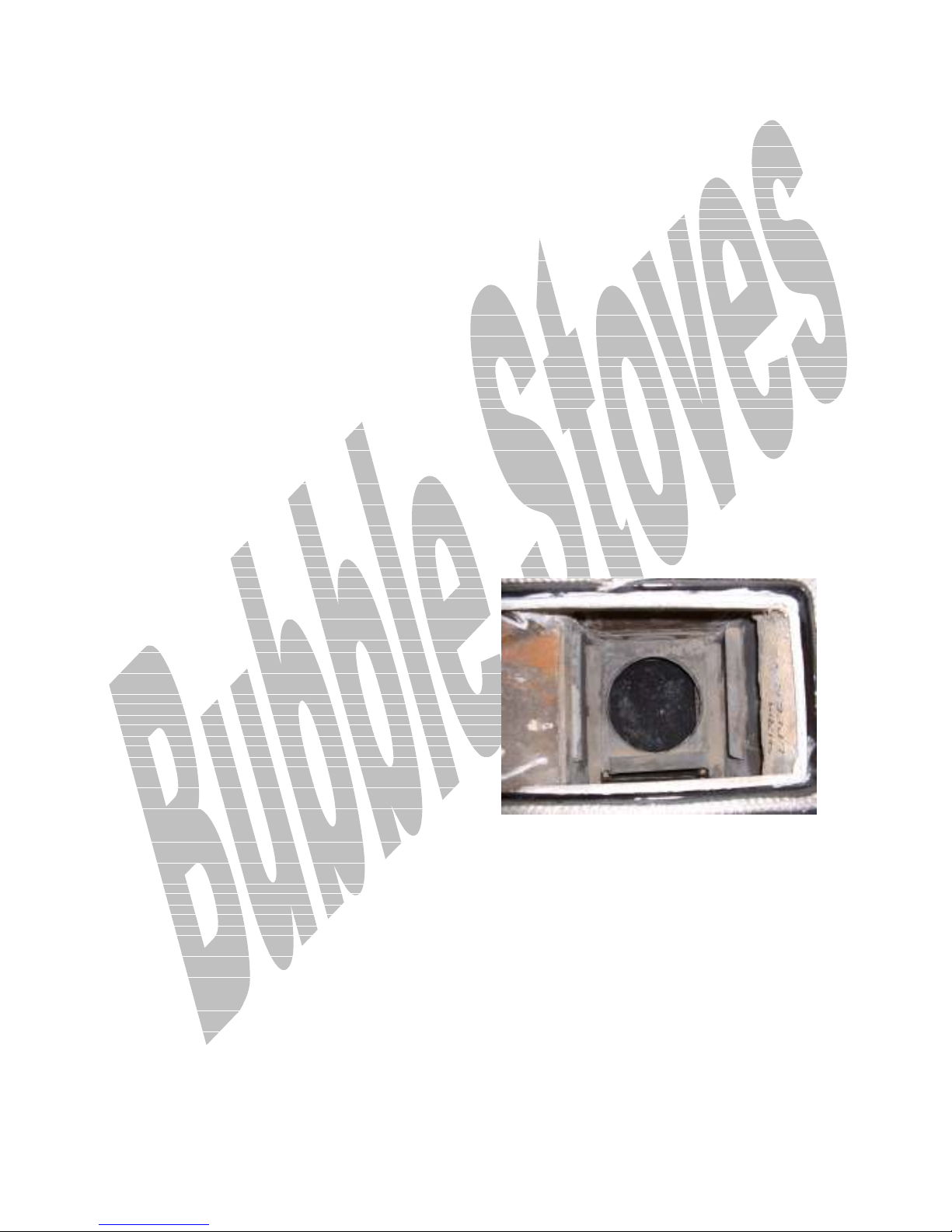
Fig 1
Shows bricks and riddling grate
removed but the cast iron grate
carrier still in place
BS4543, Specification for chimney
for oil fired appliances. Part3.
BS5449 central heating for domestic
premises Part 1 Forced circulation hot
water systems.
F
1111.. F
IITTTTIINNGG
TTHHEE KKIITT..
Clean chimney, check and adjust the
chimney vacuum (0.02" - 0.06" w.g.)
and provide a cleaning access (min
diameter 5" for linings.)
If applicable, check out the existing
hot water system.
Install fuel tank and run a fuel line up
to the firebox side of the appliance.
If necessary, modify the electrical
supply.
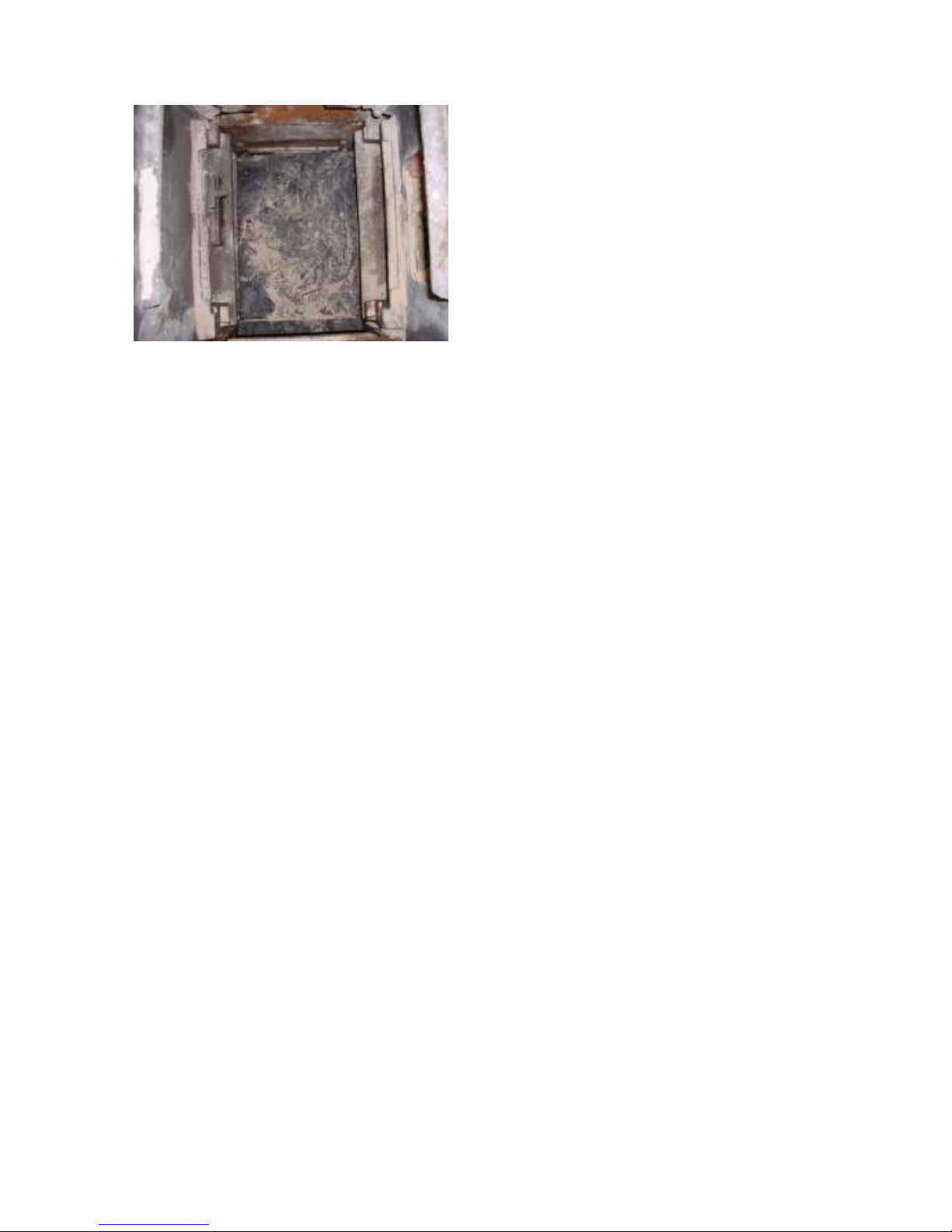
Fig 2
Shows the riddling grate and the
grate carrier removed.
Fit suitable ventilation into the
appliance site.
Remove the hot plate
Page 12
10
C
C
HHEECCKK
F
IIRREEBBRRIICCKKS
F
S
..
Check on the condition of the, sham
(opposite oven) side firebricks and if
necessary replace the upper one, a
new lower one comes in the board kit
supplied with the conversion.
Remove the fuel-loading door and
remove the cast iron protection plate
attached to it.
(Note it may be necessary to drill the
head off the old fastener and use
stillsons on the stub to remove it.)
Clean the door inner surface and paint
it with heat resistant matt black
paint.
R
EEMMOOVVEE
R
T
T
HHEE
A
A
SSHH PPAAN
N
..
Remove the ash pit base plate and
insulation, as the oil inlet supply will
have to be fitted beneath it.
It will be necessary to break the ash
pit base into small pieces to get it out.
S
T
S
EEAALL
T
HHEE
R
IIDDDDLLIINNGG
R
L
L
EEVVEER
R
..
Push the riddling lever fully in and
apply fire cement to the mechanism to
prevent any further movement.
V
T
V
AACC
T
HHEE
D
D
EEBBRRIISS
O
T
UUT
O
..
Thoroughly vacuum out all the dust
and debris. from the appliance, the
ash pan area must be free from all
traces of ash.
C
C
HHEECCKK
T
H
P
S
L
T
HHEE
H
OOTT
LLAATTEE
P
S
EEAAL
..
Make sure that the ceramic rope seal,
on to which the hotplate sits, is in
good condition and not over
compressed, if it is not forming a
good airtight seal with the closure
plate, renew it.
R
EEMMOOVVEE
R
T
F
HHEE
F
LLUUEE
T
B
B
OOXX
D
AAMMPPEERR
D
P
P
LLAATTE
E
..
Remove the sliding damper in the flue
box and seal the opening left by the
sliding damper with fire cement.
L
T
A
OOCCKK
L
T
HHEE
A
IIRR
V
AALLVVEE
V
O
N
PPEEN
O
..
It is essential that as much cooling
and combustion air as possible be
allowed to circulate around the
burner.
A permanent free air supply must be
established, as the burner cannot
function correctly without it.
To achieve this it is necessary to fully
open the spin valve which is located in
the ash pan access door and lock it
permanently in this position by use of
either a lock nut, or a (suitably
positioned) drilled hole and split pin.
F
IITTTTIINNGG
F
T
T
HHEE
B
OOAARRDDSS
B
A
P
T
A
NNDD
OOT
P
..
NOTE ALL THE PHOTOGRAPHS ARE
TAKEN FROM THE BACK OF AN
APPLIANCE EXCEPT THE FIRST
ONE.
Page 13
11
Before permanently fitting the
boards, try a dummy run, to make sure
everything fits before final
permanent fitting and fire cementing.
Remember that the pot must be
fitted in to the cooker through the
fuel loading door and the descalling
adaptor fitted later, when the pot is
in position.
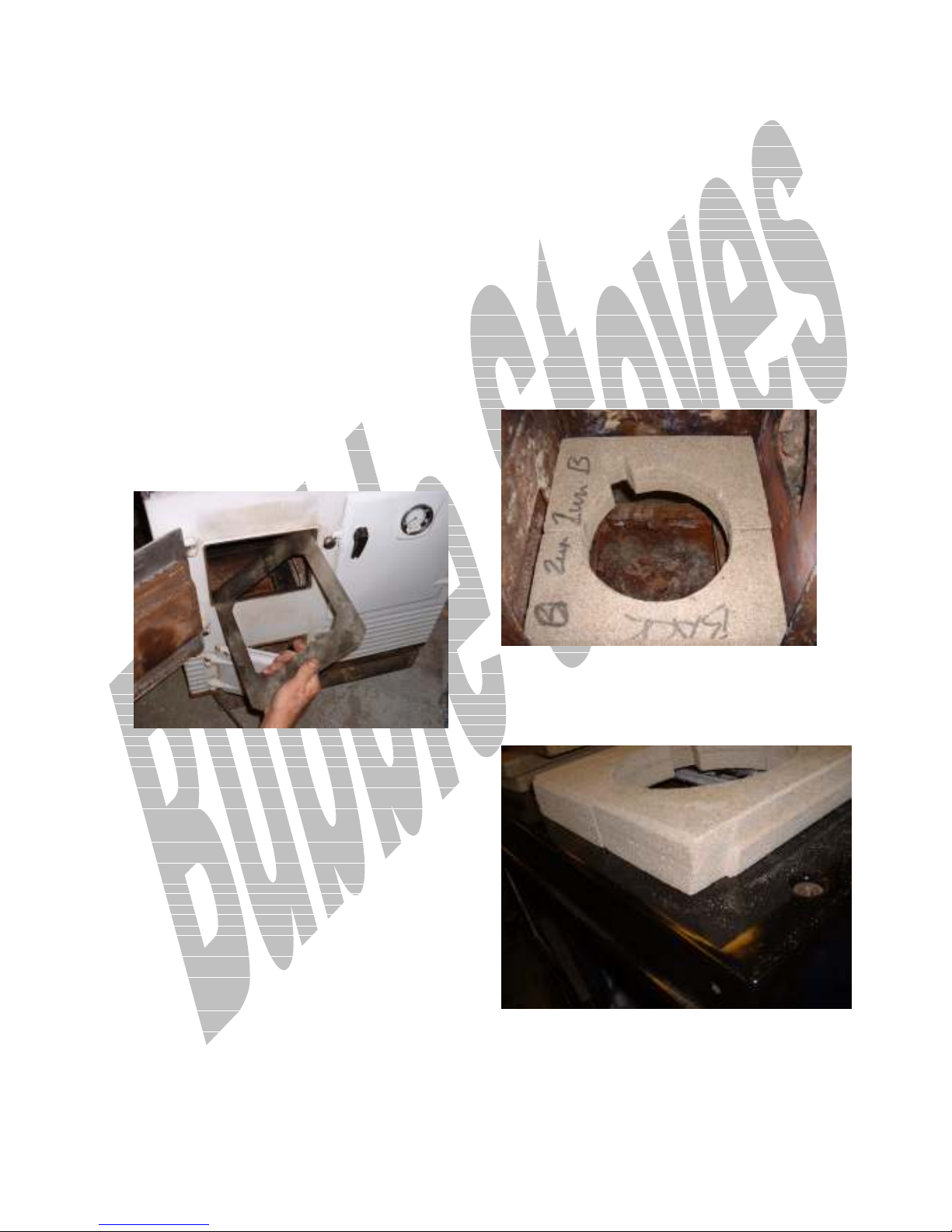
Fit the metal base closure plate
diagonally as illustrated.
If the plate does not fit, trim the
length to size.
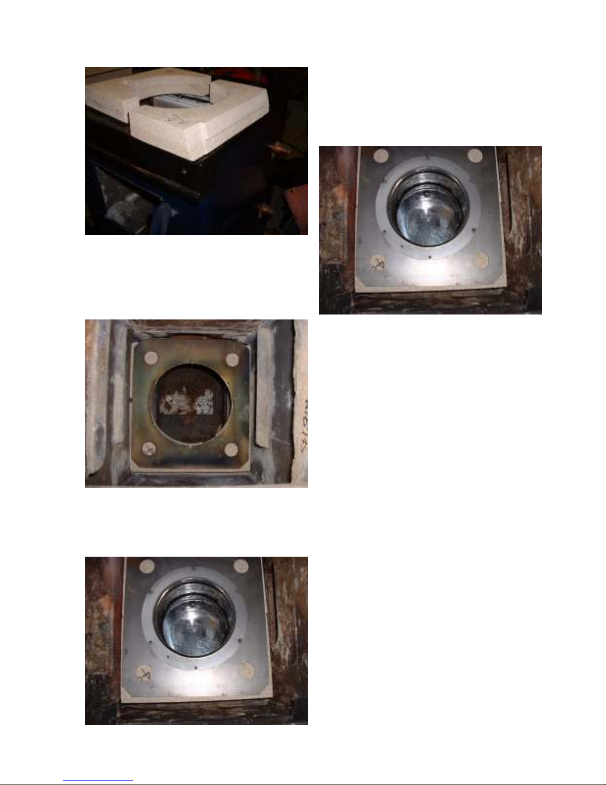
Fig 3
Note, Make sure that the base
closure plate is levelled so that oil
will flow very slightly towards the
base of the lighting port tube.
It may be necessary to trim the
boards to fit.
The back of the rear board may need
to be champhered slightly to fit up
against the rear brick or boiler
whichever is applicable.
Fig 6
The lower metal closure plate has a
rectangular cut out.
Fit it down on to the existing cast
ledge and push it to the front of the
appliance, centering it equally in the
width of the combustion chamber.
Note, there is a notch in one of the
short inner edges of the plate; this
notch should always be at the front to
the oven side.
It is provided to allow the lighting
port tube, soldered on the front of
the pot, to pass down through the
closure plate.
TRIM BOARDS AS REQUIRED FOR
NEAT FIT
FIG 6-1
FIG6-2
Page 14
12
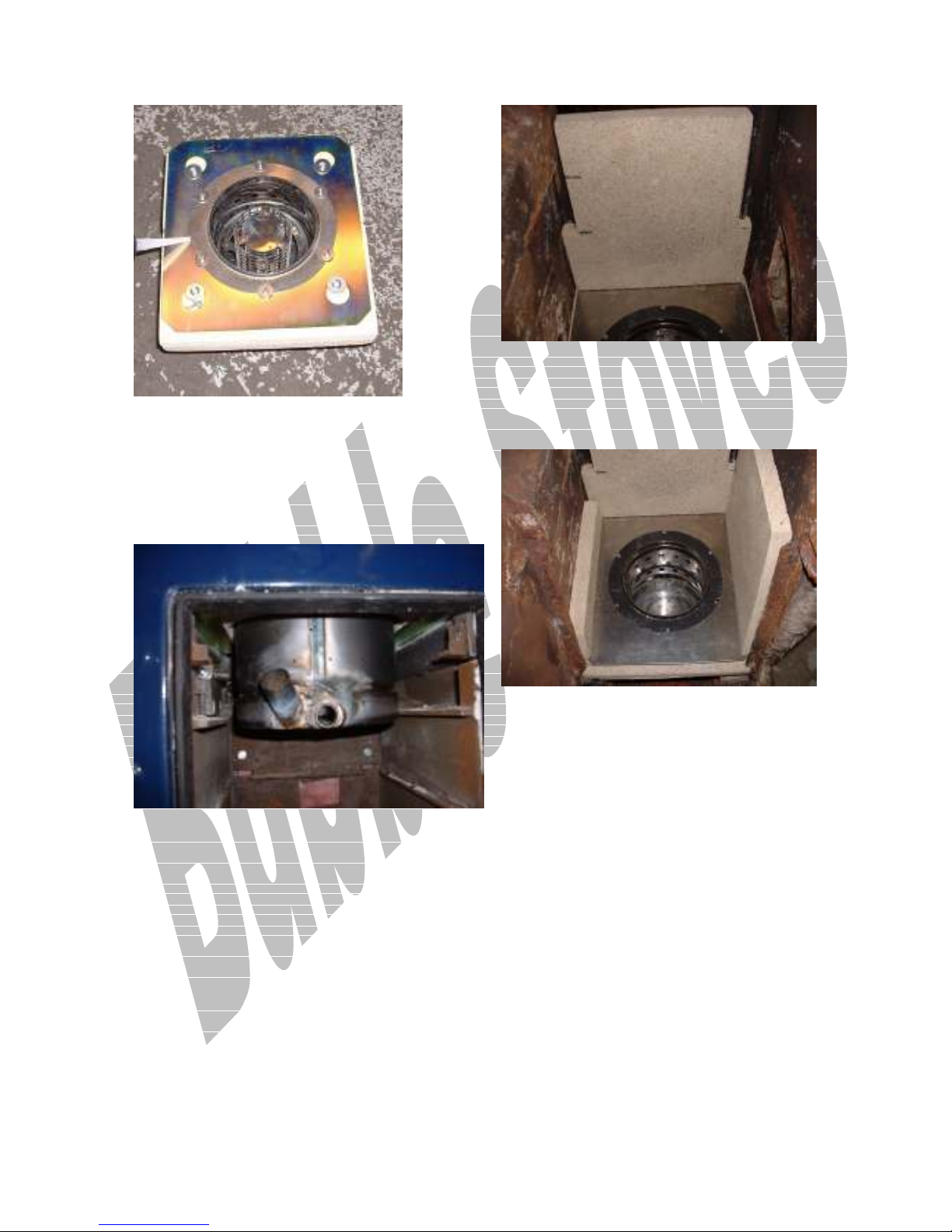
Fit top closure Plate making sure that
it is concentric about the boards.
Fit the Pot and rotate the lighting
port tube to the correct position
Fig 7b
Fig 7
Fit the Pot
Fig 7a
Note the pot comes with the
descalling device pre fitted, remove it
before fitting the pot, and refit it
afterwards.
Lower the pot through the top plate
and work it down through the boards
and lower closure plate.
Whilst this is being done the lower
plate and support boards will become
disturbed. Make sure that everything
is adjusted to fit back in its correct
place.
The 4 holes in the top plate are to
allow the two boards to be pushed up
tight together at the centre joint and
lock the board into position by using
the 4 large self tappers and repair
washers as illustrated below.
Use silicone sealant between the
closure plate and the pot mounting
flange to form an air tight gasket.
Page 15
13
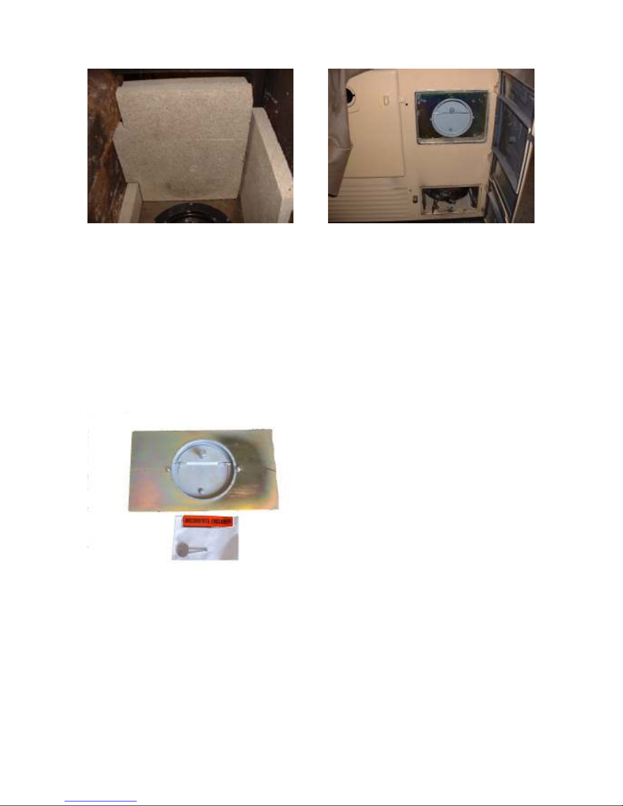
Make sure that he lighting port and oil
inlet are in the correct orientated
position.
Fig 7c shows pot orientation for a left
hand oven appliance.
Fit the Side Boards
Fig 9
Fasten the pot to the closure plate
with the M5 fasteners provided.
Fit the First Front Board
Fig 8
Fit the Second Front Board
The second front board can be pinned
or screwed to the first one.
Make sure not to pin or screw in the
area of the board where the
barometric damper will be fitted.
Fig 10
Page 16
14
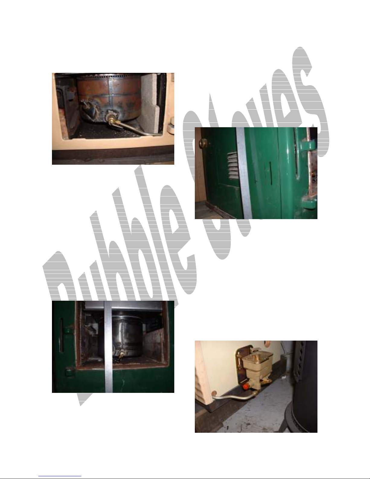
Fit the fuel-loading door masking
plate and using it as a template mark
out and cut a circle through both
boards to accommodate the
barometric damper and mounting plate
as shown in Fig 12
Fig 11
Shows the damper fitted to the
damper plate
WHEN YOU ARE HAPPY WITH THE
DUMMY RUN PROCEED AND FIT
EVERYTHING PERMANENTLY FIRE
CEMENTING THE BOARDS IN
PLACE AND FILLING ANY GAPS AS
YOU GO.
Note
1.Take care not to get fire cement
into any of the holes in the burner
pot.
2. Make sure that the base closure
plate is levelled so that oil will flow
very slightly towards the base of
the lighting port tube.
Fit the descalling device ready to
accept the oil supply pipe work.
Fig 12
Shows a left hand oven Regent with
the damper plate and burner fitted.
Carefully seal around the damper
plate with a neat fillet of silicone.
Fig 13
Page 17
15
Shows a pot fitted to a left hand
oven Regent. The side board shown in
this photo is not required.
F
T
O
IITT
HHEE
F
T
O
IILL
C
OONNTTRROOLL
C
V
V
AALLVVE
E
..
After fitting the pot, it will then be
possible to fit the oil control valve
bracket to the oil level mark
established as follows.
Measure from the floor to the 20mm
mark on the pot and transfer this
total dimension round to the
OPPOSITE OVEN side of the
appliance.
Note the photo is of a Rayburn
Supreme.
Fig 15
Measure the 20 mm from the bottom
of the pot and make a mark on the
side of the pot.
Note the photo is of a Rayburn
Supreme; the Regent will not have as
much of the pot showing.
Fig 14
Mark out and fit the oil control valve
bracket using the large dia self
tapping screws provided, by lining the
oil level notch on the side of the
bracket with the transferred mark on
the side panel.
Make sure that the valve is fitted
about 150mm back from the front
casting.
Fig 16 Left hand oven Regent
Page 18
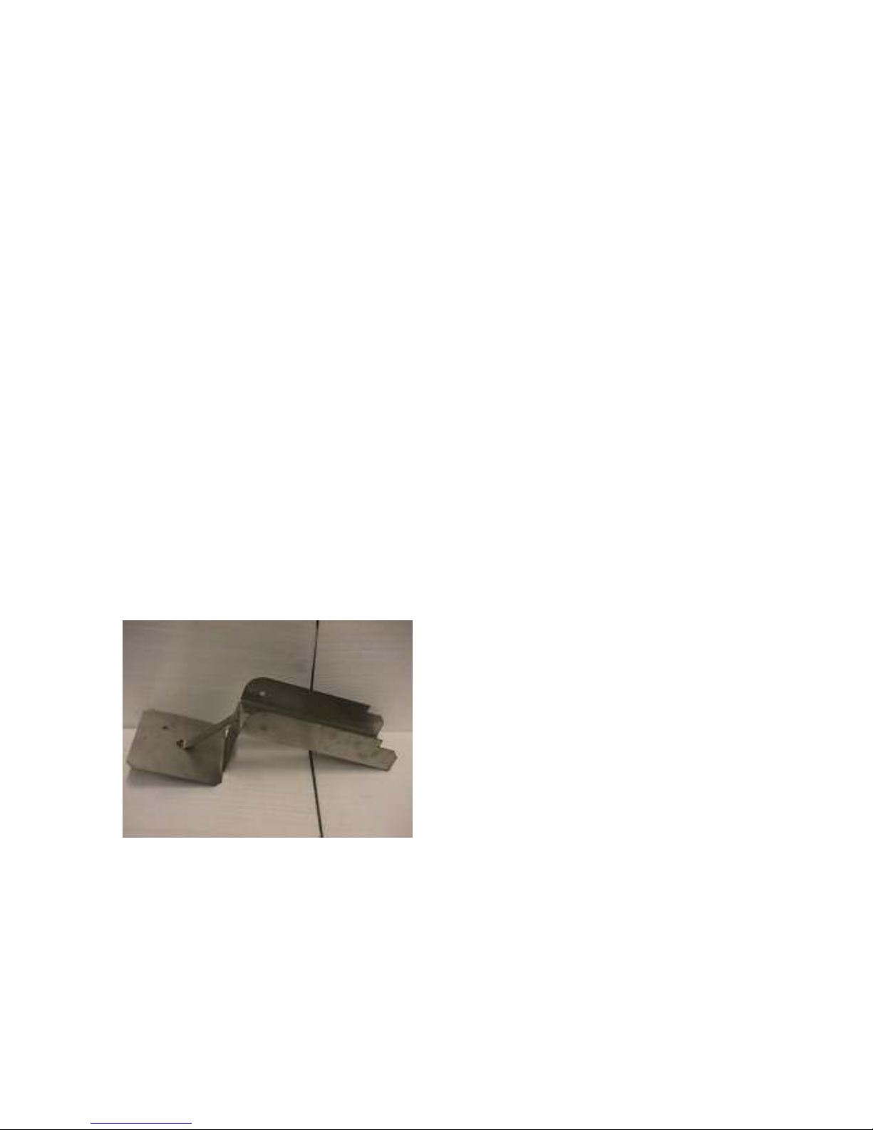
16
Using the two M8 setscrews, fit the
oil control valve to the bracket and
check that everything lines up.
Level the oil control valve in both
directions and carefully pipe up to the
burner pot, making sure that the pipe
work is accurate so as not to transfer
any lifting or twisting moments on to
the oil control valve or pot,
subsequently disturbing the now
established levels,
To get the oil feed pipe work through
the side of the appliance it will be
necessary to mark out and drill
through the inner and outer skins of
the appliance, this is an awkward job
requiring some patience.
When this is done pipe up from the oil
valve in to the descalling device.
F
IITT TTHHEE BBAAFFFFLLEE KKIIT
F
T
.
.
Fig 18
The baffle kit is awkward to fit as
the lower flat plate of the baffle has
to be fitted diagonally across the
firebox and then rotated down into
its final position with the upper part
fitting over the oven top casting and
pushed under the hob secured by an
M4 fastener, it may be necessary to
trim both the back edge of the baffle
to allow it to go under the hob and the
baffle plate which fits down into the
combustion chamber.
C
1122.. C
F
F
OOMMMMIISSSSIIOONNIINNGG AANNDD
IINNIISSHHIINNGG OOFFF
F
..
Commissioning takes the form of
separate activities as detailed -:
1. Lighting and setting up the burner
to give good combustion.
2. Setting up the appliance to perform
as per the customer’s requirements.
3. Showing the customer how to -:
3a Operate the appliance controls.
3b The fuel supply system,
3c. All of the safety features,
isolation devices, and resetting
procedures.
B
B
EEFFOORREE
T
T
EESSTT
F
F
IIRRIINNGG
T
T
HHEE
B
B
UURRNNEER
R
..
Note
(When first lighting the burner, it will
be necessary to remove the baffle, in
order to see the flame, when the
flame is set and running correctly, the
baffle must be refitted.)
Remove the hot plate
Remove the Baffle plate
Page 19

17
Remove the internals of the burner if
they have been fitted already.
Vac out the base of the burner.
Remove the barometric damper and
tape (gas tape) a piece of ceramic
glass up to the damper opening in the
front of the fuel loading door so that
you can see the flame throughout the
ignition and commissioning process.
T
T
F
E
OO
EESSTT
T
T
F
IIRRE
..
1. Turn on the oil supply to the oil
valve.
2. Turn on the electrical supply.
We supply more than one type of oil
control valve with conversions and
normally we supply a separate specific
booklet for the appropriate valve.
Refer to this booklet for all
information relative to the operation,
servicing and adjustment of the
particular valve used on this appliance.
Make sure that the valve is activated
and turned on to allow oil to flow at
its lowest setting.
Wait a few minutes until fuel starts
to flow into the pot.
(If you have any difficulties refer
to the specific valve booklet
supplied with the kit)
Look through the hot plate aperture
and down in to the base of the pot to
see if the oil is running into it.
(The oil must gather in a small pool,
at the bottom of the lighting port
tube, no bigger than a small
biscuit,)
When you can see the pool is formed
turn the oil off, refit the burner
inners
Circular flame ring
Tubular catalyser body
Refit the hot plate but not the baffle
kit.
Remove the lighting port plug and
impale a small piece of fire lighter
onto the spike.
Remember that there is a skill
involved when lighting oil burners, you
must make sure that the pot stays
alight during the lighting process and
you must also carefully control the
flow and build up of oil in the pot.
If there is a decent chimney vacuum,
oxygen in air will be drawn into the
pot to keep it alight, if there is no or
very little chimney vacuum there is a
possibility that the burner could
rapidly go out by consumption of
available oxygen in the pot and
consequently extinguish itself.
If this occurs turn the oil off to the
pot and start again after the pot has
cooled down.
DO NOT ATTEMPT TO RE LIGHT
A HOT BURNER.
Make sure that the oil is running
towards the bottom of the lighting
port tube and not away from it.
Therefore the skill is -:
Make sure that there is a chimney
vacuum.
Page 20

18
Make sure that the right quantity of
oil is in the right place.
Turn the oil on to the first position
via the flow control knob and when oil
can be seen to trickle into the pot
turn it off so as not to allow an
excessive build up.
Make sure that the oil is running
towards the bottom of the lighting
port tube.
It should gather in a small pool, at
the bottom of the lighting port
tubes, no bigger than a small
biscuit.
When the oil has formed the small
pool, turn the oil off.
Fit a small piece of firelighter on to
the lighting port plug spike, light it
and push it down into the oil at the
bottom of the lighting port tubes
making sure that it drops into the oil.
Look through the ceramic glass and
watch for signs of flames.
When the pot is running on setting 3
and the chimney has warmed up check
the chimney vacuum and make sure
that it is between .02” W.G. minimum
and .06"W.G. maximum
When you are happy with the flame
picture check the high and low fire
running.
L
F
OOWW
L
F
IIRREE
A
A
DDJJUUSSTTMMEENNT
T
..
When the burner has been running for
five minutes on position 1 LOW FIRE
the lower catalyser will be glowing dull
red, with blue flame hovering above
the catalyser, if this is not the case
adjust the low fire screw accordingly.
H
F
H
IIGGHH
F
IIRREE
A
A
DDJJUUSSTTMMEENNT
T
..
When you are happy with the low fire
running turn the burner slowly and
progressively up to full fire, this
should produce a conical wispy blue
flame with just the odd touch of
yellow. If there is excessive yellow
reduce the high fire accordingly.
You should be able to see small yellow
flames in bottom of the pot.
When you are sure that the pot is
alight, turn the fuel flow on again at
the lowest setting for 30 seconds and
then, turn it off again.
Allow another 30 seconds to elapse
and when you are sure that the pot is
alight turn the oil on to the pot and
let the flame establish on low fire.
When the pot is running on low fire
gradually turn the oil flow up to
setting 3 and let the chimney warm
up.
When you are happy with the flame
picture on high and low fire you must
then check the action of the
APPLIANCE TEMPERATURE
CONTROL mechanism if it is fitted.
When you are happy that everything
is in order, turn the burner off and
let it cool down.
S
HHUUTTTTIINNGG
S
D
OOWWN
D
N
..
Turn the oil flow control knob fully
clockwise until it is in the "0" position
Raise the safety lever of the
regulator to cut off the oil flow.
Turn the power off to the appliance.
Page 21

19
Rebuild the appliance refitting the
damper and baffle and explain to the
customer how it all works.
C
OONNTTRROOLLS
C
S
..
See the specific sheet supplied with
the equipment for valve type details.
S
1133.. S
PPEECCIIFFIICCAATTIIOONNS
S
..
Oil Control Valve
Oil Flow Rate 4cc - 12cc
(Vacuum Dependant)
Burner Gross Output 2 - 7 kW
(Vacuum Dependant)
Heat output 1.6 - 5 kW
(Vacuum Dependant)
Flue Gas Flow .0025 m/s.
3. If the burner does not burn with a
blue flame, recheck the chimney
vacuum and oil flow rate.
4. If the burners do not run well
check that the seals in the appliance
are good and that there is no ingress
of air into the appliance flue ways.
5. Check that the swinging dampers
are not jammed open.
6. Check that the correct fuel oil is
being used.
7. Check the levels of the oil valve to
pot,
33.. B
B
UURRNNEERR
R
R
UUNNSS
S
S
OOOOTTY
Y
..
If the problem has just started it
may be
F
1144.. F
11.. R
AAUULLTT
R
AACCIINNG
F
IINNDDIINNG
F
G
..
G
..
1.Audible vibrations generated by the
flame caused by too much oil in the
pot.
2. Turn off the oil flow until the
burner has settled down to a steady
burn rate and then turn the fuel on
again but don’t let the flame go out
otherwise the burner MUST be
allowed to cool down fully before a reignition is attempted.
22.. F
F
LLUUEE
V
V
AACCUUUUM
M
..
1. The pot type burner is extremely
sensitive to flue vacuum variations.
a. The fuel,
b. An unusual wind condition,
c. Damper jammed or stuck open,
causing a loss of flue vacuum.
d. Obstruction in the chimney causing
a loss of vacuum.
e. Burner to closure plate seal U.S.
f. Door not sealing.
g. Damaged door glass.
h. Burner carboned up.
j. Carbon deposits in the oil inlet pipe.
(Remove the feed pipe between the
pot and the oil valve and clean it out.)
k. Excessive fuel flow on high fire
L. Inadequate fuel flow on low fire.
2. Good combustion will not be
possible unless our instructions on
chimneys and flue vacuum are
followed.
m. Inadequate air for blue flame
combustion.
Page 22

20
2. Check that the chimney is correctly
lined and backfilled with vermiculite,
particularly important on exposed
gable end chimneys.
3. Check that the fuel is the correct
type and quality.
4. Check that the flow rates are
correct.
4a. Check the flue vacuum and all
these potential problems, before
carrying out any adjustments to the
flow rates.
5.Check that oil is flowing freely into
the pots.
55.. O
IILL
W
IILLLL
N
OOTT
E
E
NNTTEERR
T
P
T
HHEE
OOT
T
P
..
O
W
N
1. Check that the safety cut out lever
has not been accidentally shut off.
1a. Check that the isolation valves
have not been turned off.
1b Check that the fire valve has not
tripped off.
1c. Check that there is oil in the main
tank
5. Where burners are run at high fuel
flow rates on low chimney vacuums,
long unsatisfactory yellow flame
combustion and bad sooting will occur.
6. To rectify this problem reduce the
high fire flow rate screw on the Oil
Control Valve until blue flame
combustion occurs.
7. Never switch from low settings to
high settings, a longer burner life will
be achieved if the regulator is moved
only by one number at a time leaving
approx one minute between each
setting change.
44.. B
B
UURRNNEERR DDOOEESS NNOOTT LLIIGGHHTT EEAASSIILLY
Y
1. Check the level of the bottom of
the pot and make sure that the oil
flows very slightly towards the
lighting port.
..
2. If it is not possible to reset the
safety cut out lever phone us for
advice.
In case of failure of the first float
the second one catches the excess oil
and trips the safety cut out lever,
making it impossible to reset.
(OCI VALVES ONLY)
3. Simulated failure can occur if a full
oil control valve is disturbed causing
the secondary float chamber to flood.
If flooding occurs, check out the
cause before de-flooding the safety
float chamber.
To de-flood it, remove the top
aluminium cover plate and depress the
secondary float down into the
chamber to remove excess oil by
displacement.
2. Check the chimney vacuum cold.
(.02” Min)
3. Check that all the seals in the
appliance are sound.
4.Check that the swinging dampers
are not jammed open.
After excess oil is removed it will be
possible to re cock the valve.
4. Disconnect the outlet from the
valve and check for oil flow.
5. Disconnect the inlet to the
descalling device and check for oil
flow.
Page 23

21
6. Remove the descalling spindle and
check for obstructions
77.. O
O
PPEERRAATTIINNGG
F
F
LLOOWW
R
R
AATTEES
S
..
Flow rates are shown in cc per minute.
Min max
4cc 13cc
To achieve optimum burner
performance at these flow rates you
will need to have matching flue
vacuums as stated.
If the chimney does not generate
enough vacuum the flow rate will have
to be adjusted so that the burner
maintains equilibrium, i.e. blue flame
combustion.
This will result in lower output from
the appliance.
O
88.. O
IILL
S
S
MMEELLLLS
S
..
Carry out a visual check on all joints
for obvious leaks.
Check that the descalling lever
packing gland nut is adjusted.
S
1155.. S
N
N
WWAAIITT UUNNTTIILL IITT HHAASS CCOOOOLLEEDD DDOOWWN
EERRVVIICCIINNG
EEVVEERR TTRRYY TTOO RREELLIIGGHHTT AA HHOOTT BBUURRNNEER
G
..
R
,,
N
..
Full Servicing should be carried out at
six monthly intervals.
The pot should be cleaned out every 8
weeks.
Service engineers should request a
copy of the servicing schedule from
our sales desk.
Schedules will also be available from
our web site
http://www.oilstoves.co.uk
Page 24

Page 25

21
P
1166.. P
V
V
Item
No
1 Baffle 87-07-100 1
2 Plate Kit 87-15-220 1
3 Pot Assembly Complete 87-08-100D 1
4 Oil Control Valve Assembly Complete 87-08-100H 1
6 Oven Stat Assembly
7 Board Kit Complete 87-05-220 1
8 Sundries Pack 87-16-220 1
1177.. P
AACCKKIINNGG
B
AAPP
OOAARRDD
B
Description PART NUMBER Qty Check
P
AACCKKIINNGG
K
T
IIT
K
..
L
L
L
L
IISSTT
IISSTT
M
M
S
S
AAJJOORR
A
UUBB
A
A
SSSSEEMMBBLLIIEES
A
SSSSEEMMBBLLIIEES
S
..
S
..
Item
No
1 Burner Pot 78-01-170 1
1a Catalyser Body 78-01-173 1
1b Burner ring 78-01-176 1
1c Descalling Attachment 78-01-100 1
3 Oil Control Valve 78-01-010 1
3a 8mm x 8mm compression straight 77-01-717 2
3b 8mm x 8mm compression elbow 77-01-717 2
3c Oil Control Valve Support Bracket 87-01-501/16 1
3d M8 Setscrews 77-02-028 2
3e Repair Washer 77-02-111 2
3f Self tappers 77-02-151 2
3g Bundi tube for oil line x 500mm 87-01-220/3g 3
Description PART NUMBER Qty Check
4 Lower Closure plate 87-01-220/4 1
Page 26

22
4a Upper closure plate 87-01-220/4a 1
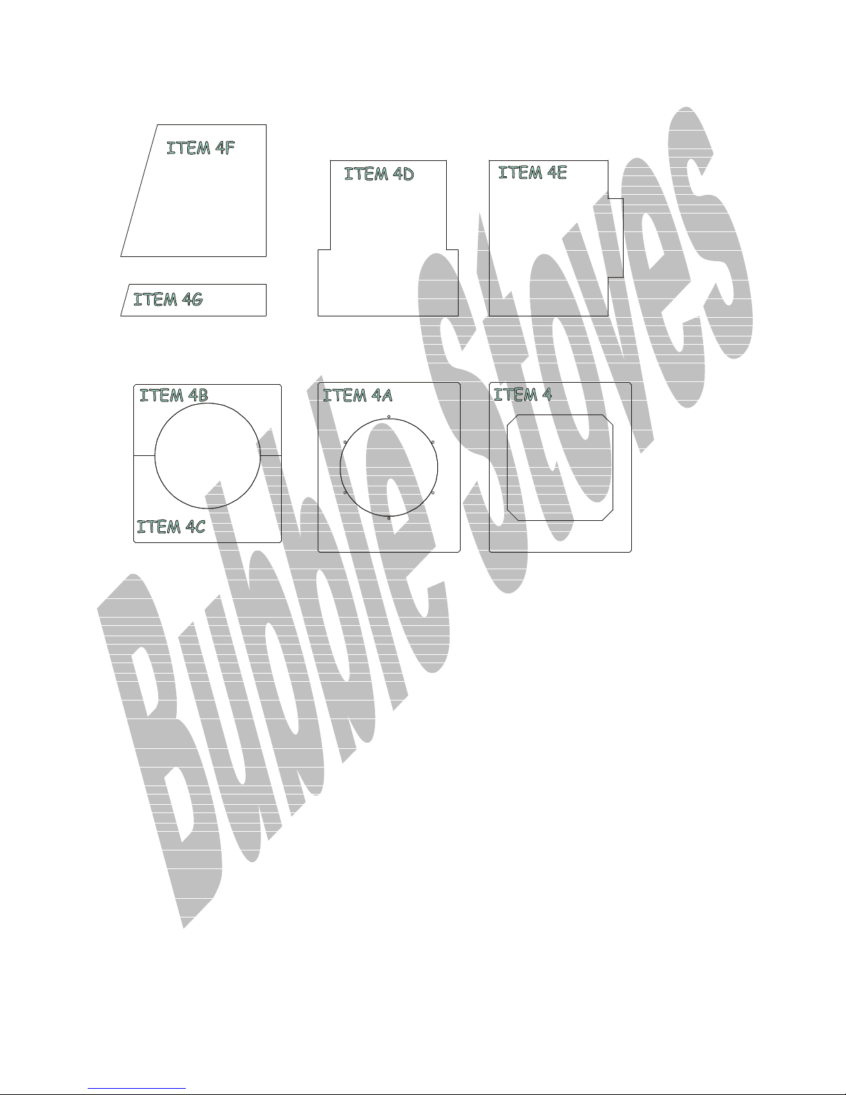
4b Front half base board
87-19-220/4b 1
4c Back half base board 87-19-220/4c 1
4d Primary Front Insulation Board 87-19-220/4d 1
4e Secondary Front Insulation Board 87-19-220/4e 1
4f Lower opposite oven side board 87-19-220/4f 1
4g Lower oven side board 87-19-220/4g 1
5 Barometric Damper mounting plate 87-18-100a 1
5a Barometric damper 78-01-200 1
6 Baffle 87-07-100 1
8 Fire Valve 77-07-004/C 1
9 User instructions 1
9a Installer instructions 1
Page 27
23
B
1188.. B
OOAARRDDSS AANNDD
C
LLOOSSUURREE
C
P
LLAATTEES
P
S
Page 28
24
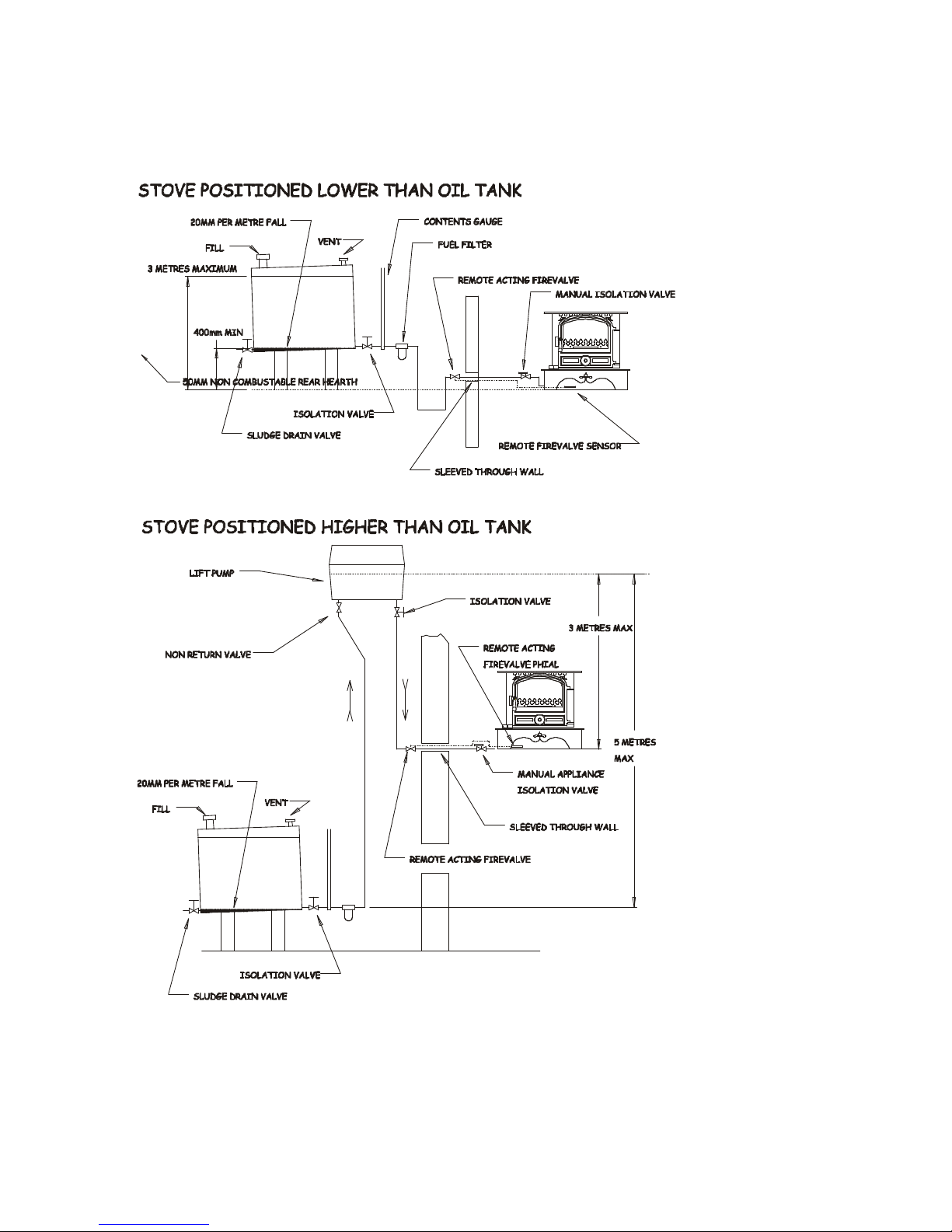
1199.. I
I
LLLLUUSSTTRRAATTIIOONNS
S
..
F
IIGG
F
O
IILL FFEEEEDD DDEETTAAIILLS
1199 O
S
..
Page 29
25
At least
1 metre
Roof pitch less than 10 degrees
At least 600mm
If 600mm
or less
If more than
600mm
At least
1 metre
Roof pitch 10 degrees or more
Opening or
adjacent
structure
At least
1 metre
If within
2.3metres
Pressure
Suction
Permanent Downdraughting
Intermittent Downdraughting
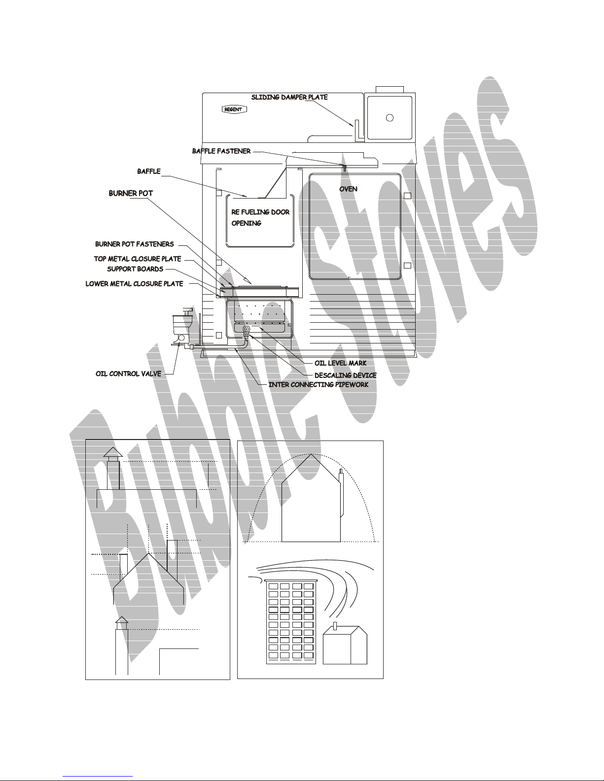
F
2200 C
C
OOOOKKEERR
IIGG
F
S
EECCTTIIOON
S
N
..
F
IIGG
F
2211 C
C
HHIIMMNNEEYY TTEERRMMIINNAALL DDEETTAAIILLS
S
..
Page 30
26
O
1199.. O
T
O
HHEE
T
O
PPTTIIOONNAALL
S
VVEENN
S
TTAAT
E
E
T
..
XXTTRRAAS
S
..
The oven stat is wired in series with the water stat and mounted in a plastic
enclosure fitted to the top, opposite oven, side panel.
The installer has to drill a 5mm dia hole in the top front corner of the appropriate
panel to allow the phial and capillary to be fed into the oven and fixed to the small
stainless steel bracket provided
The oven stat has a sensing bulb and a small diameter capillary tube which should
be carefully unwound and neatly fitted, making sure that the capillary tube and
bulb cannot be bent, trapped or damaged.
Remember damage to the tube or bulb will prevent the thermostat from
functioning.
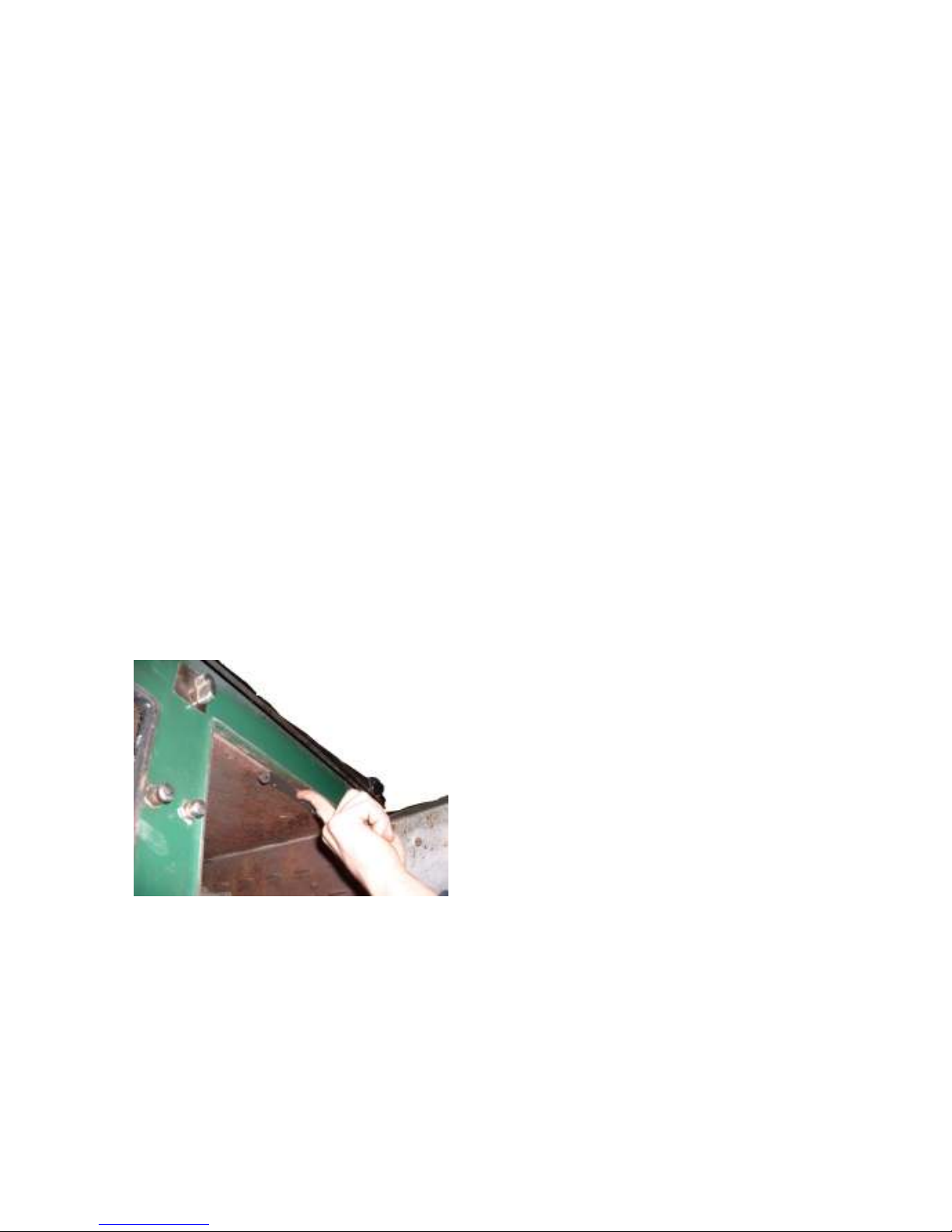
Obviously the bulb is fitted in a support bracket at the front of the oven as
illustrated below.
Note the photo is of a Rayburn Supreme.
Fig 22
The capillary runs across the front of the appliance through a guide tube located
across the front of the refuelling door.
Care must be taken when fitting the guide tube which is positioned so as to allow
the subsequent, convenient replacement of the stat should it ever fail.
The bundi guide tube is fitted into a trough, which the installer has to cut into the
front board above the cut out for the swinging barometric damper.
When the damper and plate are fitted it should cover the bundi conduit tube.
Page 31

27
© HARWORTH HEATING LTD 30.6.98
This publication may not be copied by any means, without written permission from the authors.
This product is subject to continuous development and improvement and it is consequently acknowledged that due to this
process there may be some omissions and errors.
This publication is intended only to assist the reader in the use of this product and therefore Harworth Heating Ltd shall
not be liable for any loss or damage whatsoever arising from the use of any information, error or omission found in this
guide.
Only approved personnel, WHO HAVE BEEN SUITABLY TRAINED, may carry
out maintenance on this product.
 Loading...