

Page 1
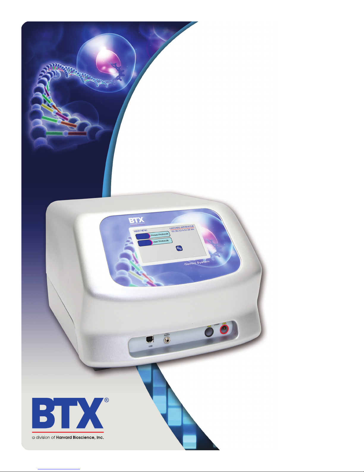
Gemini Series
Twin Waveform
Electroporation Systems
User’s Manual
www.btxonline.com
5507-002 REV 1.0
Page 2

Safety Information
Please read the following safety precautions to ensure proper
use of your generator. If the equipment is used in a manner not
specified, the protection provided by the equipment may be
impaired.
To Prevent Hazard or Injury
Caution
Protective Ground
Terminal
Caution Risk of
Electric Shock
Use Proper Line Cord
Use only the specified line cord for this product and make sure line
cord is certified for country of use.The operating voltage range for
the BTX Gemini Twin Wave Series is 100-240 vac, 50-60 Hz.
Ground the Product
This product is grounded through the grounding conductor
of the power cord. To avoid electric shock, the grounding
conductor must be connected to earth ground. Before making
any connections to the input or output terminals of the product,
ensure that the product is properly grounded.
Make Proper Connections
Make sure all connections are made properly and securely. Any
signal wire connections to the unit must be no longer than 3
meters.
Observe All Terminal Ratings
Review the operating manual to learn the ratings on all
connections.
Use Proper Fuse
Use only specified fuses with product.
Avoid Exposed Circuitry
Do not touch any electronic circuitry inside of the product.
High Voltage Risk
Do Not Operate with Suspected Failures
If damage is suspected on or to the product do not operate the
product. Contact qualified service personnel to perform inspection.
Orient the Equipment Properly
Do not orient the equipment so that it is difficult to operate the
disconnection device.
Place Product in Proper Environment
Review the operating manual for guidelines for proper operating
environments.
Observe All Warning Labels on Product
Read all labels on product to ensure proper usage.
toll free 800.272.2775 • 508.893.8999 • www.btxonline.com
Gemini Series Electroporator User’s Manual
2
Page 3

A Message from BTX
Thank you for investing in a Gemini System.
Since its founding in 1983, the main focus of BTX has been in the area of applying controlled electric fields for
genetic engineering applications. Because of this, we quickly established a reputation as the technological leader
in the fields of electroporation and electrofusion. Our systems have been installed in many prestigious institutes
around the globe where they are used successfully for high efficiency transfection, transformation and cell fusion
applications. We offer a variety of waveforms, electrodes and chamber options to provide you with the tools to
achieve your goals.
We are vested in your success. To that end, the BTX technical support team constantly tracks published literature
for any reference to electroporation and electrofusion. We extract the pertinent experimental conditions and yields
from these papers to help us in our efforts to help you. In addition to tracking publications, we are available to you
for support at any time for advice in experimental design, product recommendations, troubleshooting, and any
other relevant technical advice.
We thank you again for your investment and we look forward to assisting you in any way we can.
Finally, please read this manual carefully before attempting to operate the electroporation system. If you have any
questions about the unit or about particular applications, please contact us:
BTX
84 October Hill Rd
Holliston, MA 01746 USA
Toll Free: 1-800-272-2775
International Callers: 508-893-8999
Fax: 508-429-5732
Web: www.btxonline.com
Email: [email protected]
For any customers outside the US or Canada, please call your local BTX dealer or call us directly.
toll free 800.272.2775 • 508.893.8999 • www.btxonline.com
Gemini Series Electroporator User’s Manual
3
Page 4

Table of Contents
Safety Information .......................................................................................................................2
Introduction .................................................................................................................................3
Table of Contents ........................................................................................................................4
Product Overview ........................................................................................................................5
Electroporation Overview ............................................................................................................6
General Optimization Guide for Electroporation .................................................................... 7-8
Wave Forms ..................................................................................................................................... 7
Field Strength ................................................................................................................................... 7
Pulse Length ..................................................................................................................................... 8
Number of Pulses ............................................................................................................................. 8
Electroporation Buffer ...................................................................................................................... 8
DNA/RNA Concentrations ................................................................................................................. 8
Applications ........................................................................................................................... 9-11
Mammalian Cell Transfection ............................................................................................................ 9
In Vivo, In Utero, In Ovo ................................................................................................................... 9
Bacteria and Yeast Transformation .................................................................................................... 9
Plant and Insect Transfection ............................................................................................................ 9
References ........................................................................................................................................ 9
General References ...................................................................................................................... 9-11
Glossary of Terms ......................................................................................................................12
Electroporation Buffers .............................................................................................................13
Unpacking the System ...............................................................................................................14
Touchscreen Button Reference ..................................................................................................15
Software Setup .................................................................................................................... 16-17
Setting Time/Date ........................................................................................................................... 16
Setting Audible Alarm Preferences .................................................................................................. 16
Setting Backlight Preferences .......................................................................................................... 17
Displaying Device Information ........................................................................................................ 17
Preset Protocols ................................................................................................................... 18-20
Using Preset Protocols .................................................................................................................... 18
Customizing a Preset Protocol ................................................................................................... 19-20
Performing Experiments ...................................................................................................... 20-26
Creating New Protocols .................................................................................................................. 21
Creating an Exponential Decay Wave Protocol ..................................................................... 21-23
Creating a Square Wave Protocol ........................................................................................ 24-26
Using Specialty Protocols .................................................................................................... 27-29
Using an HT Plate Handler ......................................................................................................... 27-28
Using Specialty Electrodes ......................................................................................................... 28-29
Managing Protocols ............................................................................................................. 30-32
Saving a Copy of a Protocol ............................................................................................................ 30
Renaming a Protocol ...................................................................................................................... 30
Deleting a Protocol ......................................................................................................................... 31
Password Protecting a Protocol ....................................................................................................... 32
Protocol Manager Software ................................................................................................ 33-35
Installation ..................................................................................................................................... 33
Overview ........................................................................................................................................ 33
Upload– Generator to PC ................................................................................................................ 33
Download– PC to Generator ........................................................................................................... 34
Upload Log Files ............................................................................................................................. 35
Remote Control Software ..........................................................................................................36
Generator Specifications ..................................................................................................... 37-38
Maintenance ..............................................................................................................................39
Upgrading Gemini Series Software ..................................................................................... 40-42
SB Virtual Commport Driver Installation ..................................................................................... 40-41
Device Updater Program ................................................................................................................. 42
Error Messages & Troubleshooting ..................................................................................... 43-45
Ordering Information .......................................................................................................... 46-47
Warranty Information ................................................................................................................48
Declaration of Conformity .........................................................................................................49
toll free 800.272.2775 • 508.893.8999 • www.btxonline.com
Gemini Series Electroporator User’s Manual
4
Page 5

Product Overview
The BTX Gemini X2 is a highly advanced twin waveform
generator incorporating both square and exponential decay waves
in a single unit. The BTX Gemini X2 has been designed with
these waveform combinations to enable researchers to easily and
efficiently electroporate eukaryotic cells and prokaryotic cells in
all forms with one easy to use setup. The BTX Gemini X2, which
can be operated via PC or remote control, boasts a wide range
of voltage (5-3000 v, 1 v or 5 v increments), pulse length (10
μS – 1S, 1 μS resolution), time constant options (which include
capacitance choices from 25 to 3275 μF in LV and 10, 25, 35, 50,
60, 75, 85 μF in HV), along with multiple pulsing options with
both the square waveform and the exponential decay waveform,
and unparalleled pulse delivery accuracy. The BTX Gemini X2,
with over 1,000 custom protocol storage, monitors and displays
pre-pulse sample resistance as well as delivered voltage values and
records logs of all experiment parameters internally, which can be
downloaded to a computer for analysis and QC. The generator
is controlled through a color LCD touch screen interface and
incorporates USB communications. The pulse can also be
activated by a foot switch. The enhanced safety features of the
BTX Gemini X2 protect users as well as precious samples. The BTX
Gemini X2 is designed to give researchers the ultimate flexibility in
their experiments, making it possible to perform electroporation
on tissues and organs in vivo (as well as in utero, in ovo, ex plant)
on adherent cells, and cells in suspension in either single cuvettes
or 96 well plates. The Safety Dome allows researchers to safely
work with electroporation cuvettes, up to two at a time, giving
researchers the ability to experiment on sample volumes from
20 μl up to 800 μl. This state of the art system comes complete
with the twin waveform generator for cell electroporation in
all forms, dozens of preprogrammed protocols for commonly
electroporated cells, Safety Dome, 30 cuvettes, cuvette stand, user
manual, two year warranty, unlimited application support and the
same high quality researchers have come to expect from BTX.
The BTX Gemini SC is a twin waveform generator incorporating
both square and exponential decay waves in a single unit. These
waveform combinations enable researchers to easily and efficiently
electroporate eukaryotic and prokaryotic cells in suspension with
one easy to use setup. The BTX Gemini SC boasts a wide range of
voltage (10-3000 v, 5 v or 10 v increments), pulse length
(50 μS – 5 mS, 50 μS resolution), time constant options (which
include capacitance choices from 25 to 3275 μF in LV and 10, 25
or 50 μF in HV), multiple pulsing option with the square waveform
and unparalleled pulse delivery accuracy. The BTX Gemini SC,
with unlimited custom protocol storage, monitors and displays
pre-pulse sample resistance as well as delivered voltage values.
The generator is controlled through a color LCD touch screen
interface. The enhanced safety features of the BTX Gemini SC
protect users as well as precious samples. The Safety Dome allows
researchers to safely work with electroporation cuvettes, up to
two at a time, giving researchers the ability to experiment on
sample volumes from 20 μl up to 800 μl. This affordable system
comes complete with the dual waveform generator for suspension
cell electroporation, dozens of preprogrammed protocols for
commonly electroporated cells, Safety Dome, 30 cuvettes, cuvette
stand, user manual, two year warranty, unlimited application
support and the same high quality researchers have come to
expect from BTX.
What is the difference between
the Gemini X2 and the Gemini SC?
The Gemini X2 is designed to give researchers the ultimate control
and flexibility in their experiments by making it possible to perform
electroporation on tissues and organs in vivo (as well as in utero,
in ovo, ex plant) on adherent cells, as well as cells in suspension in
either single cuvettes or 96 well plates, can be controlled remotely
via footswitch or PC, and it offers storage of pulse data. Because
of the Gemini X2’s broad range of use, the specifications are wideranging, making the Gemini X2 the most versatile electroporation
system available today.
The Gemini SC is designed for researchers working to electroporate
cells in suspension in cuvettes. This system cannot accommodate
multiple pulsing with the exponential decay waveform, remote
operation, specialty electrodes or 96 well options. For this reason,
some of the specifications of the Gemini SC are not as extensive as
what is available in the Gemini X2.
toll free 800.272.2775 • 508.893.8999 • www.btxonline.com
Gemini Series Electroporator User’s Manual
5
Page 6

Electroporation Overview
DNA Delivery Into Cells Using Electroporation
General Electroporation Discussion
Electroporation is the use of a transmembrane electric field pulse
to induce microscopic pathways (pores) in a bio-membrane. Their
presence allows molecules, ions, and water to pass from one side
of the membrane to the other. When the electric field is applied the
ions inside and outside the cell membrane migrate. As the charge
builds up on either side of the membrane the membrane weakens
and the pathways form permitting material outside of the cell to
enter. If the electric field is promptly removed the pathways close
and the membrane reseals. If the electric field duration is too long
the pathways increase and the cell is killed. Efficient electroporation
depends on proper selection of electric field waveforms. The
electropores are located primarily on the membrane areas which
are closest to the electrodes. The pathways form in about a
microsecond and seal in seconds to minutes. The duration of the
electric field is tens of microseconds to tens of milliseconds.
The use of electroporation was described by Neumann in the early
1980’s. The routine use of electroporation became very popular
with researchers through the 1980’s because it was found to be a
practical way to place drugs, or other molecules into cells. In the
late 1980’s, scientists began to use electroporation for applications
in multi-cellular tissue.
In the early 1990’s Lluis Mir of the Institute Gustave-Roussy was the
first to use electroporation in a human trial to treat external tumors.
Research has shown that the induction of pathways is affected by
three major factors. First, cell-to-cell biological variability causes
some cells to be more sensitive to electroporation than other
cells. Second, for pathways to be induced, the product of the
pulse amplitude and the pulse duration has to be above a lower
limit threshold. Third, the number of pathways and effective
pathway diameter increases with the product of “amplitude” and
“duration.” Although other factors are involved, this threshold
is now understood to be largely dependent on a fourth factor,
the reciprocal of cell size. If the upper limit threshold is reached
pore diameter and total pore area are too large for the cell to
repair by any spontaneous or biological process, the result is
irreversible damage to the cell or cell lysis. Because the mechanism
of electroporation is not well understood, the development of
protocols for a particular application has usually been achieved
empirically, by adjusting pulse parameters (amplitude, duration,
number, and inter-pulse interval).
Research shows that certain experimental conditions and
parameters of electrical pulses may be capable of causing many
more molecules to move per unit time than simple diffusion. There
is also good evidence (Sukharev et al., 1992) that DNA movement
is in the opposite direction.
An additional important consideration is when the voltage pulse is
applied to the cells and medium that the amount of current that
flows is dependent on the conductivity of the material in which
the cells are located. Some material is quite conductive and severe
heating will occur if the pulse duration is too long. Therefore
long duration fields will kill cells by destroying the membrane and
heating.
toll free 800.272.2775 • 508.893.8999 • www.btxonline.com
The electric field in which the cells are located is produced by two
system components. The first is the voltage waveform generator
and the second is the electrode which converts the voltage into
the electric field.
As the charge accumulates at the membrane, which is a
capacitance, the voltage across the membrane increases.
voltage = capacitance charge
As charge accumulates at the membrane, the voltage across
the membrane increases. Neumann et al. (1989) described the
equation that relates the transmembrane voltage (TMV) to electric
field intensity:
where:
Pores in the membrane will begin to form as the voltage increases
from its quiescent value of a few tenths of a volt to more than 0.5
volts. To produce a TMV of 1 volt across the membrane of a cell
with 7μm radius, the required electric field intensity is:
2
E= =
3
The number of pores and effective pore diameter increase as the
product of pulse amplitude and duration increase. At the upper
limit threshold, pore diameter and total pore area become too
large for the cell to repair by any spontaneus or biological process.
The result is irreversible damage to the cell or cell lysis.
Another important point to consider is the generation of heat
during electroporation. Heat production is directly related to
current intensity which is, in turn, dependent on the conductivity
of the material through which the electric field is applied. Standard
saline solutions such as PBS and many tissue culture media are
highly conductive and, thus will generate considerable amounts of
heat when used in cell electroporation. Excessive heating can be
detrimental to cell viability. The effects of heating can be reduced
by using a low conductivity medium such as BTX’s Cytoporation
medium to resuspend cells prior to electroporation.
Although electroporation is an effective method for introducing
macromolecules onto cells, the biological mechanisms by which
cells become electroporated are not completely understood.
Therefore, the development of specific protocols for particular
applicatons is usually achieved by empirical adjustment of pulse
parameters (i.e. amplitude, duration, pulse number, and interpulse
interval).
Gemini Series Electroporator User’s Manual
6
*
1
7 x 10
950 volts/cm
-4
Page 7

General Optimization Guide for Electroporation
As described, electroporation is the application of controlled
direct current (DC) electrical pulses which are applied to living
cells and tissues for a short duration of time. The pulse induces a
transmembrane potential which causes the reversible breakdown
of the cellular membrane. This action results in the permeation
or “pore formation” of the cell membrane which allows small
molecules (such as dye, oligonucleotides or peptides) and large
molecules (such as proteins, DNA and RNA) to be introduced into
the cell. During this process the cellular uptake of the molecules
continues until the pores close, which can take milliseconds to
minutes.
Optimization of the electroporation process involves several
factors. Choosing the wave form, determining field strength
and adjusting pulse length are just a few critical variables.
Other parameters which play a crucial role in optimization
include cell diameter, plasmid concentrations, temperature and
electroporation buffer.
Wave Forms
Pulse shape generally falls into two categories, square wave or
exponential decay wave:
Square Wave Pulse
Square wave pulses rise quickly to a set voltage level, maintain
this level during the duration of the set pulse length and quickly
turn off. Square waves yields higher efficiencies and viabilities in
mammalian cells. Square wave EP in in vivo and ex vivo tissues,
embryos, and plant protoplast applications yield better results in
comparison to an exponential decay wave.
Exponential Decay Wave Pulse
Exponential decay waves generate an electrical pulse by allowing
a capacitor to completely discharge. As a pulse is discharged
into a sample, the voltage rises rapidly to the peak voltage set
then declines over time. The powerful exponential decay wave
pulse is routinely used for transformation of gram-negative and
gram-positive, bacterial, yeast, plant tissues, insect cells and some
mammalian cells.
Field Strength
The field strength is measured as the voltage delivered across an
electrode gap and is expressed as kV/cm. Field strength is critical
to surpassing the electrical potential of the cell membrane to allow
the temporary reversible permeation or “pore formation” to occur
in the cell membrane. Three factors should be considered for
optimizing field strength:
1. Electrode Gap Size
2. Cell Diameter
3. Temperature
Cell Type Field Strength Ranges
Bacteria/Yeast: 3-24 kV/cm
Mammalian: 0.25-3 kV/cm
Plant: 3-12 kV/cm
Electrode Gap Size
The distance between electrodes, or “gap size” is important when
optimizing your electroporation experiment. Field strength is
calculated using voltage divided by gap size. For example, using
a 4mm gap cuvette with 500V would provide a field strength of
1.25kV/cm. If instead of a 4mm gap cuvette, a 2mm gap cuvette
was used, the voltage would have to be reduced by half or to
250V in order to maintain the same field strength of 1.25kV/
cm. It is possible to derive the voltage needed to accomplish
electroporation if the desired field strength and gap size are
known. The calculation for this is Field strength (kV) multiplied by
gap size (cm) equals voltage. For example, if a user was certain
that a 1.25 kV/cm field strength was required in a 1mm gap
cuvette the calculation would be: 1.25kV x 0.1cm= 0.125kV or
125V.
Example: A field strength of 1.25 kV/cm
4mm gap cuvette = 500V
2mm gap cuvette = 250V
1mm gap cuvette = 125V
Cell Diameter
Generally, smaller cell sizes require higher voltages while larger
cell diameters require lower voltages for successful cell membrane
permeation.
Temperature
The temperature at which cells are maintained during
electroporation effects the efficiency of the electroporation
for several reasons. The majority of mammalian cell lines are
effectively electroporated at room temperature. Samples which
are pulsed at high voltage or exposed to multiple pulses and
long pulse durations can cause the sample to heat up. These
conditions cause increased cell death and lower the transfection
efficiency. Maintaining the sample at lower temperatures can
diminish the heating effects on cell viability and efficiency. Since
electroporation causes the transient formation of pores, keeping
the cells at a lower temperature following the pulse may allow
the pores to remain open longer to allow more uptake of the
exogenous molecules. Yet lower temperatures on other cell
lines can be damaging and cause high cell mortality. This effect
is specific to each cell line and should be considered during
optimization studies. The standard pulse voltage used for cells
at room temperature will need to be approximately doubled for
electroporation at 4°C in order to effectively permeate the cell
membrane.
toll free 800.272.2775 • 508.893.8999 • www.btxonline.com
Gemini Series Electroporator User’s Manual
7
Page 8
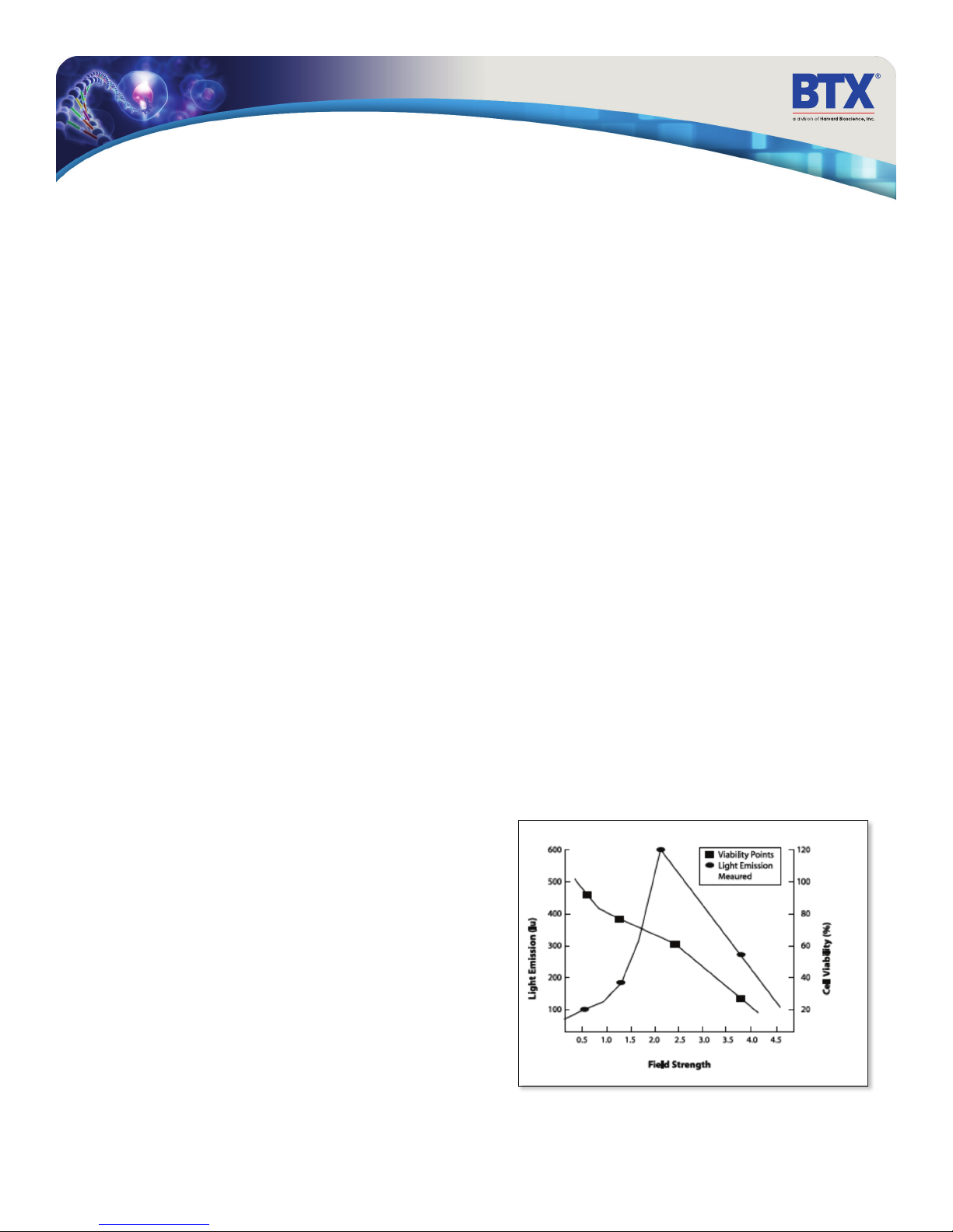
General Optimization Guide for Electroporation
Pulse Length
The pulse length is the duration of time the sample is exposed
to the pulse. This is measured as time in micro to milliseconds
ranges. Adjusting this parameter is dependent on the pulse wave
form. The pulse length in a square wave system can be inputted
directly. The pulse length in an exponential decay wave system
is called the “time constant” which is characterized by the rate
at which the pulsed energy (e) or voltage is decayed to 1/3 the
original set voltage. This time constant is modified by adjusting
the resistance and capacitance (RC) values in an exponential decay
wave form. Time constant calculation T=RC, where T is time and R
is resistance and C is capacitance.
The pulse length works indirectly with the field strength to increase
pore formation and therefore the uptake of target molecules.
Generally, during optimization of parameters an increase in
voltage should be followed by an incremental decrease in pulse
length. When decreasing the voltage, the reverse is true. Pulse
length is a key variable that works hand in hand with voltage and
needs to be considered when optimizing electrical parameters to
maximize the results for a given cell type.
Number of Pulses
Electroporation is typically carried out as a single pulse for most
cell types. However, other cell lines may require multiple pulses
to achieve maximum transfection efficiencies. Usually lower
voltages are used when applying multiple pulses in order to
gradually permeate the cell membranes. This allows the transfer
of molecules while avoiding damage to delicate or whole tissue
samples. This method of multiple pulsing is critical for maximum
gene delivery without causing tissue damage to in vivo, in utero
and explant tissue environments. The use of multiple pulse will
require the optimization of key electrical parameters including
voltage and pulse length. Typically, for in vivo applications the use
of lower voltages between 10-100 volts with pulse lengths ranging
30-50msec provides efficient transfection. The optimal voltage,
pulse length and number of pulses will vary depending on the cell
type and molecule (DNA or RNA) transfected.
resistance of the sample which in turn will affect the pulse length
or time constant of the pulse. The volume of liquid in a cuvette
has significant effect on sample resistance for ionic solutions, the
resistance of the sample is inversely proportional to the volume of
solution and pH. As the volumes are increased resistance decreases
which increases the chance of arcing, while lowering the volume
will increase the resistance and decrease the arc potential.
BTX now offers BTXpress High Performance Electroporation
Solution, a low conductance buffer that achieves higher
transfection efficiencies with minimal cell toxicity. The BTXpress
buffer is a single buffer developed to facilitate high efficiency gene
delivery into mammalian cells.
DNA/RNA Concentrations
Electroporation is typically thought of as a nucleic acid (DNA,
mRNA, siRNA and miRNA) transfer method into prokaryotic and
eukaryotic cells. Electroporation is not limited to just nucleic acid
delivery, it can introduce proteins, antibodies, small molecules
and fluorescent dyes. The standard range of DNA used for
transfections is 5-20g/ml for most cell types; however in some
instances increasing the DNA concentration as high as 50g/
ml improves transfection efficiency without changing other
parameters. Determining the optimal DNA concentration through
a DNA titration can be beneficial. The size of a molecule will have
an effect on the electrical parameters used to transfect the cell.
Smaller molecules (siRNA or miRNA) may need higher voltage
with microsecond pulse lengths and larger molecules (DNA) may
need lower voltages with longer pulse lengths. Buffers such as
EDTA or Tris can drastically reduce the transfection efficiency.
Therefore, we recommend resuspending DNA in distilled water.
Finally, electroporating ligation mixtures into E.coli can cause
arcing and reduced transformations. Diluting the ligation mixture a
minimum of 1:5 with diH2O, dialysis, or ethanol precipitation can
significantly improve transformation efficiencies and reduce the
potential for arcing.
Electroporation Buffer
The buffers used for electroporation can vary depending on the
cell type. Many applications use highly conductive buffers such
as PBS (Phosphate Buffered Saline <30 ohms) and HBSS (Hepes
Buffer <30 ohms) or standard culture media which may contain
serum. Other recommended buffers are hypoosmolar buffers in
which cells absorbs water shortly before pulse. This swelling of
the cells results in lowering the optimal permeation voltage while
ensuring the membrane is more easily permeable for many cells
but can be damaging to others. Prokaryotic cells such as bacteria
require the use of high resistance buffers (>3000 ohms) for this
reason proper preparation and washing of the cells is essential
to remove excess salt ions to reduce the chance of arcing. Ionic
strength of an electroporation buffer has a direct affect on the
toll free 800.272.2775 • 508.893.8999 • www.btxonline.com
Gemini Series Electroporator User’s Manual
8
Page 9

Applications
Mammalian Cell Transfection
Electroporation is a highly flexible technique used to genetically
modify mammalian cells. Whether you are studying up or down
regulation of genes, specific protein expression. This method
is non-toxic and requires no expensive reagents to successfully
transfect your cells. Primary cells, stem cells or established cell lines
can be electroporated with yield high transfection efficiencies and
great cell survival rates.
In Vivo, In Utero, In Ovo
Square wave systems allow researchers to set the pulse lengths
and number of pulses, which is critical to ensure viable cells and
tissues while still maintaining efficient transfection both in vivo and
ex vivo. Electroporation mediated gene and drug delivery has been
shown to substantially increase intracellular uptake and expression
of DNA, siRNA and miRNA in muscle, skin, liver, kidney, testis,
retina, tumors, etc. In vivo electroporation has successfully been
used in embryo applications, in utero and in ovo applications in
addition to transfection of Zebra fish.
Bacteria and Yeast Transformation
Electroporation has long been recognized as the most efficient
means of transforming both gram negative and gram positive
bacteria and yeast. Gramnegative bacteria such as coli or
Helicobacter pylori are generally easier to transform than
grampositive bacteria (e.g. Streptococcus pneumoniae) due to
their cell wall composition. Transformation efficiencies of 1x10
transformants/μg DNA are commonly seen for gram-negative
bacteria, while for gram-positive bacteria, generally 1x10
10
6
transformants/μg DNA are achievable.
Plant and Insect Transfection
Electroporation of plant tissue can be used to generate transgenic
crops that are useful in agricultural/horticultural applications.
Insect models are also widely used throughout the scientific
community to study development and gene regulation and
function. The ability to introduce genes or molecules is essential to
researchers working with either of these two species. This is why
researchers consistently turn to BTX for all of their electroporation
needs.
References
Jonathan M. Dermott, J. M. Gooya, B. Asefa, S. R. Weiler, M. Smith, J.
R. Keller. Inhibition of Growth by p205: A nuclear protein and putative
tumor suppressor expressed during Myeloid Cell differentiation. Stem
Cells 22:832-848. 2004
JonathanM. Quinlan, Wei-Yuan Yu, MarkA. Hornsey, David Tosh
andJonathan MWSlack. In vitro culture of embryonic mouse intestinal
epithelium: cell differen-tiation and introduction or reporter genes.
BMC Developmental Biology 6:24. 2006
YangbingZhao, ZhiliZheng, Cyrille J. Cohen, Luca Gattinoni, Douglas
C. Palmer, Nicholas P. Restifo, Steven A. Rosenberg, and RichardA.
Morgan. High-efficiency transfection ofprimary human and mouse
Tlymphocytes using RNA electropora-tion. Molecular Therapy (2006)
13, 151–159
William J. Buchser, Jose R. Pardinas, Yan Shi, John L. Bixby, and
VanceP. Lemmon. 96-Well electroporation method for transfection of
mammalian central neurons. BioTechniques Vol. 41, no. 5.2006
K. Regha, AjitK. Satapathy and Malay K. Ray. RecD plays an essential
function during growth at low temperature in the Antarctic Bacterium
Pseudomonas syringae Lz4W. Genetics 170: 1473-1484. August2005
Victor B. Busov, R. Meilan, D.W. Pearce, C. Ma, S. B. Rood, andS.
H. Strauss. Activation Tagging of a dominant Gibberellin catabolism
gene (GA 2-oxidase) from poplar that regulates tree stature. Plant
Physiology, Vol. 132, pp. 1283-1291. July 2003
Jun Ishikawa, Kazuhiro Chiba, Haruyo Kurita, and Hiroyuki Satoh.
Contribution of rpoB2 RNA Polymerase‚ Subunit Gene to Rifampin
Resistance in Nocardia Species. Antimicrobial Agents Chemotherapy,
50(4):1342-1346. April 2006
Bindu Garg, Romesh C. Dogra, and Parveen K. Sharma. High-Efficiency
Transformation of Rhizobium leguminosarum by Electroporation.
Applied Environmental Microbiology. 65(6):2802-2804. June 1999
General References
In Vitro Electroporation
Kim, T. et. al., Mesoporous Silica-Coated Hollow Manganese Oxide
Nanoparticles as Positive T1 Contrast Agents for Labeling and MRI
Tracking of Adipose- Derived Mesenchymal Stem Cells. J. Am. Chem.
Soc., 133, 2955–2961, 2011
Kataoka, N. et. al., Development of butanol-tolerant Bacillus subtilis
strain GRSW2-B1 as a potential bioproduction, AMB Express, 1:10,
2011
Hutson, T.H. et. al., Optimization of a 96 well electroporation assay
for post natal rat CNS neurons suitable for cost–effective mediumthroughput screening of genes that promote neurite outgrowth.
Frontiers in Molecular Neuroscience; 4(55): December 2011
Djouad, F. et. al., Activin A expression regulates multipotency of
mesenchymal progenitor cells. Stem Cell Res & Therapy, 1(11), 2010
Sankaranarayanan , K. et. al., Electro-Molecular Therapy using Adult
Mesenchymal Stem Cells. Proc. ESA Annual Meeting on Electrostatics,
13, 2010
Blackmore, M. et. al., High content screening of cortical neurons
identifies novel regulators of axon growth. Molecular and Cellular
Neuroscience, 44, 43 -54, 2010
Yao, S. et. al., Improvement of electroporation to deliver plasmid DNA
into dental follicle cells. Biotechnol J. October ; 4(10): 1488–1496.
2009
Rinaldi, G., Development of Functional Genomic Tools in Trematodes:
RNA Interference and Luciferase Reporter Gene Activity in Fasciola
hepatica. PLoS One, 2(7); e260, July 2008
Nguyen, K. et al., T Cell Costimulation via the Integrin VLA-4 Inhibits
the Actin-Dependent Centralization of Signaling Microclusters
Containing the Adaptor SLP-76. Immunity, 28, 810–821, June 2008
Yang, C. et al., Dimeric heat shock protein 40 binds radial spokes
for generating coupled power strokes and recovery strokes of 9 + 2
flagella. The Journal of Cell Biology, 180(2), pp. 403-415, January 28,
2008
toll free 800.272.2775 • 508.893.8999 • www.btxonline.com
Gemini Series Electroporator User’s Manual
9
Page 10

Applications
General References (continued)
In Vitro Electroporation (continued)
Zhao, Y. et al., High-Efficiency Transfection of Primary Human and
Mouse T Lymphocytes Using RNA Electroporation. Molecular Therapy,
Vo. 13, No. 1, January 2006
Heaney, J.D. et. al. Tissue-specific expression of a BAC transgene
targeted to the Hprt locus in mouse embryonic stem cells. Genomics,
2004
Raoul, C. et al., Motoneuron Death Triggered by a Specific Pathway
Downstream of Fas: Potentiation by ALS-Linked SOD1 Mutations.
Neuron, Vol. 35, 1067-1083, September 12, 2002
Dawson, K. et al., Insulin-Regulated Trafficking of Dual-Labeled
Glucose Transporter 4 in Primary Rat Adipose Cells, Biochemical and
Biophysical Research Communications. 287, pp. 445–454, 2001
In Vitro Electroporation
Johannson, D. et. al., Intradermal Electroporation of Naked Replicon
RNA Elicits Strong Immune Responses. PLoS ONE, 7(1): e29732, 2012
Daftarian, P. et. al., In vivo Electroporation and Non-protein Based
Screening Assays to Identify Antibodies Against Native Protein
Conformations. Hybridoma, 30(5); 2011
Hallengard, D. et. al., Comparison of plasmid vaccine immunization
schedules using intradermal in vivo electroporation. Clinical Vaccine
Immunology, 2011
Bolhassani, A. et. al., Improvement of different vaccine delivery systems
for cancer therapy. Molecular Cancer, 10(3), 2011
Li, W. et. al., The Effects of Irreversible Electroporation (IRE) on Nerves.
PLoS ONE, 6(4), 2011
Lladser, A. et. al., Intradermal DNA electroporation induces survivinspecific CTLs, suppresses angiogenesis and confers protection against
mouse melanoma. Cancer Immunol Immunother, 59; 81-92, 2010
Shi, W. et al., Generation of sp3111 transgenic RNAi mice via
permanent integration of small hairpin RNAs in repopulating
spermatogonial cells in vivo. Acta Biochim Biophy Sci, 42(2): p 116,
2010
Haller, BK. et. al., Therapeutic efficacy of a DNA vaccine targeting the
endothelial tip cell antigen delta-like ligand 4 in mammary carcinoma.
Oncogene, 29, 4276-4286, 2010
Guo, Y. et. al., Irreversible Electroporation Therapy in the Liver:
Longitudinal Efficacy Studies in a Rat Model of Hepatocellular
Carcinoma. Cancer Research; 70(4) February 15, 2010
Roos, A. K. ,Skin Electroporation: Effects on Transgene Expression,
DNA Persistence and Local Tissue Environment. PLoS ONE, 4(9) e7226,
2009
Brave, A. et. al., Late administration of plasmid DNA by intradermal
electroporation efficiently boosts DNA-primed T and B cell responses to
carcinoembryonic antigen. Vaccine, 27, 3692-3696, 2009
Roos, A. K. et. al., Optimization of Skin Electroporation in Mice to
Increase Tolerability of DNA Vaccine Delivery to Patients. Molecular
Therapy, 17(9), 1637-1642, Sep 2009
Danner, S. et. al., Seminiferous tubule transfection in vitro to define
post-meiotic gene regulation. Reproductive Biology and Endocrinology,
7(67), 2009
Benton, C. et al., Modest PGC-1_ Overexpression in Muscle in Vivo
Is Sufficient to Increase Insulin Sensitivity and Palmitate Oxidation in
Subsarcolemmal, Not Intermyofibrillar, Mitochondria*. The Journal of
Biological Chemistry, 283(7); pp. 4228–4240, February 15, 2008
Chesler, A. T., Selective Gene Expression by Postnatal Electroporation
during Olfactory Interneuron Neurogenesis. PLoS ONE, 3(1): e1517,
2008
Rao, N. M. et al., Electroporation of Adult Zebrafish. S. Li (ed.),
Electroporation Protocols: Preclinical and Clinical Gene Medicine.
Methods in Molecular Biology, Vol. 423. p 289, 2008
Johnson, C. J. et al., Technical Brief: Subretinal injection and
electroporation into adult mouse eyes. Molecular Vision, 14:22112226, 2008
Heller, L. et. al., Comparison of electrically mediated and liposomecomplexed plasmid DNA delivery to the skin. Genetic Vaccines and
Therapy, 6(16), 2008
Roos, A.K., et. al., Enhancement of Cellular Immune Response to
a Prostate Cancer DNA Vaccine by Intradermal Electroporation.
Molecular Therapy, 13(2), February 2006
Kong, X. C. et al., Inhibition of synapse assembly in mammalian muscle
in vivo by RNA interference. EMBO Rep, 5(2): 183-188, January 2004
Pringle, I. A. et al., Duration of reporter gene expression from
naled pDNA in the mouse lung following direct electroporation and
development or wire electrodes for sheep lung electroporation studies.
Molecular Therapy, 9, S56–S56, 2004
Mikata, K. et al., Inhibition of Growth of Human Prostate Cancer
Xenograft by Transfection of p53 Gene: Gene Transfer by
Electroporation. Molecular Cancer Therapeutics, Vol. 1, 247–252,
February 2002
Pekarik, V. et al., Screening for gene function in chicken embryo using
RNAi and electroporation. Nature Biotechnology, 21: 93-96, December
2002
Dujardin, N. et. al., In vivo assessment of skin electroporation using
square wave pulses. J Controlled Release, 79, 219-227; 2002
Drabick, J.J. et. al., Cutaneous Transfection and Immune Responses to
Intradermal Nucleic Acid Vaccination Are Significantly Enhanced by in
Vivo Electropermeabilization. Molecular Therapy, 3(2), Feb 2001
In Utero Electroporation
Maiorano, N. A., et al., Promotion of embryonic cortico-cerebral
neuronogenesis by miR-124. Neural Development, 4:40, 2009
Ex Vivo Electroporation
Deora, A.A. et. al., Efficient Electroporation of DNA and Protein into
Confluent and Differentiated Epithelial Cells in Culture. Traffic, 8:
1304-1312, 2007
Thomas J-L. et. al., Electroporation, an alternative to biolostics for
transfection of Bombyx mori embryos and larval tissues. Journal of
Insect Science, 3:17, 2003
Dimitrov, D.S., and Sowers, A.E., (1990) Membrane electroporation fast molecular exchange by electroosmosis. Biochimica et Biophysica
Acta 1022: 381-392.
toll free 800.272.2775 • 508.893.8999 • www.btxonline.com
Gemini Series Electroporator User’s Manual
10
Page 11

Applications
General References (continued)
Ex Vivo Electroporation (continued)
Deora, A.A. et. al., Efficient Electroporation of DNA and Protein into
Confluent and Differentiated Epithelial Cells in Culture. Traffic, 8:
1304-1312, 2007
Thomas J-L. et. al., Electroporation, an alternative to biolostics for
transfection of Bombyx mori embryos and larval tissues. Journal of
Insect Science, 3:17, 2003
Dimitrov, D.S., and Sowers, A.E., (1990) Membrane electroporation fast molecular exchange by electroosmosis. Biochimica et Biophysica
Acta 1022: 381-392.
Sukharev SI, Klenchin VA, Serov SM, Chernomordik LV and
Chizmadzhev YA, (1992) Electroporation, and electrophoretic DNA
transfer into cells: The effect of DNA interaction with electropores,
1992, Biophys J. 63: 1320-1327.
Nickoloff, Jac A., ed. (1995) Plant Cell Electroporation and
Electrofusion Protocols, Methods in Molecular Biology, Volume 55.
(Humana Press, Totowa, New Jersey).
E. A. Disalvo and S.A. Simon, eds. (1995) Permeability and Stability of
Lipid Bilayers (CRC Press, Boca Raton), p 105-121.
Chang, D.C., Chassy, B.M., Saunders,J.A. and Sowers, A.E., eds. (1992)
Guide to Electroporation and Electrofusion, (Academic press, San
Diego), 581 pp.
Neuman, E., Sowers, A.E., and Jordan, C.A.., eds. (1989)
Electroporation and Electrofusion in Cell Biology, (Plenum Press, New
York) 581 pp.
Bartoletti, D. C., Harrison, G. I., & Weaver, J. C. (1989). The number of
molecules taken up by electroporated cells: quantitative determination.
FEBS Lett., 256, 4-10.
Djuzenova, C. S., Zimmermann, U., Frank, H., Sukhorukov, V.
L., Richter, E., & Fuhr, G. (1996). Effect of medium conductivity
and composition on the uptake of propidium iodide into
electropermeabilized myeloma cells. Biochim.Biophys.Acta, 1284, 143-
152.
Klenchin VA, Sukharev SM, Chernomordik LV, Chizmadzhev YA,
Electrically induced DNA uptake by cells is a fast process involving DNA
electrophoresis, 1991, Biophys J. 60:804-811 Neumann, E., Kakorin,
S., & Toensing, K. (1999). Fundamentals of electroporative delivery of
drugs and genes. Bioelectrochem.Bioenerg., 48, 3-16.
Neuman, E., Toensing, K., Kakorin, S., Budde, P., & Frey, J. (1998).
Mechanism of electroporative dye uptake by mouse B cells.
Biophys.J., 74, 98-108. Sukharev, S. I., Klenchin, V. A., Serov, S. M.,
Chernomordik, L. V., & Chizmadzhev, Y. (1992). Electroporation and
electrophoretic DNA transfer into cells. The effect of DNA interaction
with electropores. Biophys.J., 63, 1320-1327.
Wolf, H., Rols, M. P., Boldt, E., Neumann, E., & Teissie, J. (1994).
Control by pulse parameters of electric field-mediated gene transfer in
mammalian cells. Biophys.J., 66, 524-531.
Zerbib, D., Amalric, F., & Teissie, J. (1985). Electric field mediated
transformation: isolation and characterization of a TK+ subclone.
Biochem.Biophys.Res.Commun., 129, 611-618.
toll free 800.272.2775 • 508.893.8999 • www.btxonline.com
Gemini Series Electroporator User’s Manual
11
Page 12

Glossary of Terms
Capacitance – The ability of a body to store an electrical charge.
Any object that can be electrically charged exhibits capacitance.
Capacitor – A device that stores energy in the form of an electric
field. A capacitor consists of two metal plates insulated from each
other by a dielectric (insulating, usually a plastic material such as
Mylar) material. In an ideal capacitor, no conduction current flows
between the plates after the capacitor is completely charged.
Capacitors can be fixed, variable, or adjustable.
Cell Form – The format in which cells present for experimentation.
Cell forms include suspension, in vivo, in ovo, ex plant, adherent,
whole organism, etc.
Dielectric Breakdown – The reversible breakdown of bilipid layer membranes as a result of the application of a DC
electroporation pulse. A sufficiently high field strength may
increase the membrane potential past a critical point leading to
the breakdown of the membrane.
Dielectric Constant – For a given dielectric (nonmetallic)
material, the ratio of electrical capacitance of a dielectric-filled
capacitor to a vacuum capacitor of identical dimensions.
Divergence – The deviation of field lines (e.g. electric field lines)
from parallel, homogeneous conditions. A highly divergent field is
a very inhomogeneous field where the value and direction of the
field change drastically in the area under consideration.
Electrolytic – A fluid containing charged molecules is called an
electrolyte. Electrolytic properties are associated with such a fluid,
such as the ability to conduct current.
Electroporation – The application of high electric field pulses of
short duration to create temporary pores (holes) in the membranes
of cells.
Electroporation Cuvette – Square chambers with electrodes on
two sides, usually measuring 1 mm, 2 mm or 4 mm in gap, for
the purpose of electroporating cells in suspension. The cell type
being electroporated typically determine the gap. Prokaryotic cells
typically uses 1 mm or 2 mm gap cuvettes, while eukaryotic cells
will typically use 2 mm or 4 mm gap sizes.
Exponential Decay Waveform – This waveform is mainly used
for transforming cells during electroporation. In this type of pulse
the set voltage is released from the capacitor and decays rapidly
and exponentially over time (millisecs). The delivered pulse, is
characterized by two parameters: the field strength (kV/cm) and
the time constant. These parameters can be adjusted by varying
voltage and capacitance settings to achieve a wide pulse gradient.
Field Strength – The potential difference between two points
(electrodes) (in Volts) divided by the distance between the
electrodes (called gap, and expressed in cm). Expressed as V/cm or
kV/cm. This is true only if the electric field is homogeneous as it is
in parallel plate electrodes.
Gap – The distance between electrodes.
Homogeneous Electric Field – The direction and field strength
are constant.
Hydrostatic Pressure – The pressure in liquids at rest.
Inhomogeneous Electric Field – Direction and strength of the
electric field vary.
Number of Pulses – The number of pulses the sample will be
exposed to.
Osmotic Pressure – The applied pressure required to prevent
the flow of solvents of different concentration across a semipermeable membrane.
Pore – A small, mostly transient opening in a cell wall caused by
the application of a brief high electric field pulse.
Potential Difference – The difference (in Volts) between points
in an area between electrodes.
Protocols – The method for performing an experiment.
Pressure Gradient – The difference in pressure between two
points in a medium.
Pulse Interval – The time between multiple pulses.
Pulse Length/Pulse Duration – The length of time an electric
signal is applied.
Specialty Electrodes – Electrodes used with the BTX Gemini
X2 to perform electroporation on a wide variety of cell forms.
Some applications include in vivo, in ovo, in utero, or ex plant
electroporation. BTX offer many types of specialty electrodes.
Square Waveform – This waveform is typically used for
eukaryotic cells. It is characterized by the voltage delivered, the
duration of the pulse, the number of pulses and the length of the
interval between pulses.
Time Constant – (represented by the Greek letter tau, T) is the
amount of time required for the actual voltage of the delivered
pulse to decrease to a value 1/e of the true peak pulse.
Transfection – The introduction of nucleic acids into animal cells.
Stable transfections result in integration of nucleic acids into host
chromosomes and the inheritance of associated traits in progeny
cells. Transient transfections result in temporary expression of
exogenous nucleic acids.
Transformation – The introduction of nucleic acids into
microorganisms and plant cells.
Turgor Pressure – The pressure in capillaries.
Voltage – The difference of electric potential between two
electrodes (expressed in volts (V) or kilovolts (kV)).
Waveforms – The shape of time-varying electric signals.
toll free 800.272.2775 • 508.893.8999 • www.btxonline.com
Gemini Series Electroporator User’s Manual
12
Page 13

Electroporation Buffers
There are many kinds of buffers and medium used for
electroporating cells. Typically, we recommend using
medias without serum or antibiotics.
The following is a list of the most commonly used buffers/
medium:
BTXpress – is a single buffer solution, developed to quickly and
efficiently deliver genes into mammalian cells that were previously
considered “hard to transfect” by chemical and other non-viral
methods. This solution, in combination with BTX electroporators,
provides researchers with the versatility needed for success
across a broad range of cell types while maintaining critical cell
viability. Transfection using this high performance electroporation
solution is equally effective in delivering DNA as well as siRNA into
mammalian cells.
PBS – is a buffer solution commonly used in biological research. It
is a water-based salt solution containing sodium chloride, sodium
phosphate, and, in some formulations, potassium chloride and
potassium phosphate. The buffer’s phosphate groups help to
maintain a constant pH. The osmolarity and ion concentrations of
the solution usually match those of the human body (isotonic).
HEPES – is widely used in cell culture, largely because it is better
at maintaining physiological pH despite changes in carbon dioxide
concentration (produced by cellular respiration) when compared to
bicarbonate buffers, which are also commonly used in cell culture.
RPMI – is a form of medium used in cell culture and tissue culture.
It has traditionally been used for growth of Human lymphoid cells.
This medium contains a great deal of phosphate and is formulated
for use in a 5% carbon dioxide atmosphere.
Water & 10% glycerol – Typically used for bacteria
Cytoporation Media T – is a buffer designed for larger volume
cell electroporation as it incorporates a low conductivity of 0.08 S/
cm to reduce heating of solution during electroporation.
Cytoporation Media T4 – is a buffer designed for larger volume
cell electroporation as it incorporates a low conductivity of 3.45
mS/cm to reduce heating of solution during electroporation.
Opti-MEM – is an improved Minimal Essential Medium (MEM)
that allows for a reduction of Fetal Bovine Serum supplementation
by at least 50% with no change to growth rate or morphology.
Opti-MEMt can be used with a variety of suspension and adherent
mammalian cells, including Sp2, AE-1, CHO, BHK-21, HEK, and
primary fibroblasts.
MEM Eagle – is suitable for a diverse spectrum of mammalian cell
types. Various formulations available with either Hank’s or Earle’s
salts.
DMEM – MEM is used in a wide range of mammalian cell culture
applications. The high glucose version is well suited to high density
suspension culture. The low glucose formula is used for adherent
dependent cells.
CytoMix – is a composition of cytokines for the highly efficient
and reproducible expansion of human multipotent mesenchymal
stromal cells (MSCs).
toll free 800.272.2775 • 508.893.8999 • www.btxonline.com
Gemini Series Electroporator User’s Manual
13
Page 14
Unpacking the System
The shipping carton in which your BTX Gemini Twin Waveform
Electroporation System is packed has been specifically designed
to provide maximum protection to the instrument during
transportation and normal handling conditions. Upon receipt, the
carton should be examined for any external damage resulting from
shipment.
Open the carton and carefully remove the BTX Gemini Twin
Waveform Electroporator and inspect the unit for any apparent
damage. Save the carton and packing materials for future
transportation and shipping requirements.
Packing Data
Check the packing slip to ensure that all items ordered and listed
are included in the shipment. Inform BTX immediately if any parts
are missing or damaged.
Power Source
As received, the instrument is ready for use with either 100-240 V
AC, 50/60 HZ.
The power requirements are 350 watts. In the USA, the power
cord has a standard three prong plug.
Installation
Once you have determined that the components of the system
have not sustained any obvious damage in shipment, proceed with
the installation. The location of the BTX Gemini Twin Waveform
Electroporator should be a dry, level, sturdy surface free from
extremes in ambient temperature, dust or chemical exposures.
Unpack the safety dome, cuvette rack and disposable cuvette
chambers.
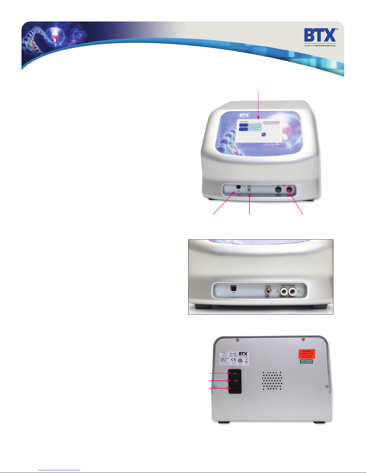
Connect the safety dome, or in the case of the BTX Gemini
X2 system, specialty electrodes or HT plate handler, into the
connectors at the bottom right-hand side of front panel.
Connect the mains/power cord to into the back panel at the
bottom left.
Power up the system by pushing the rocker switch located on the
back panel at the bottom left. The display will flash the BTX logo.
Once the software initializes, the Main Menu screen will appear.
You are now ready to begin your work.
Touchscreen Display
USB Serial Input Footswitch Input
(switch sold separately)
Gemini SC
High Voltage Output
toll free 800.272.2775 • 508.893.8999 • www.btxonline.com
Fuse Holder
Main Power Switch
Universal Power Input
Gemini Series Electroporator User’s Manual
14
Page 15
Touchscreen Button Reference
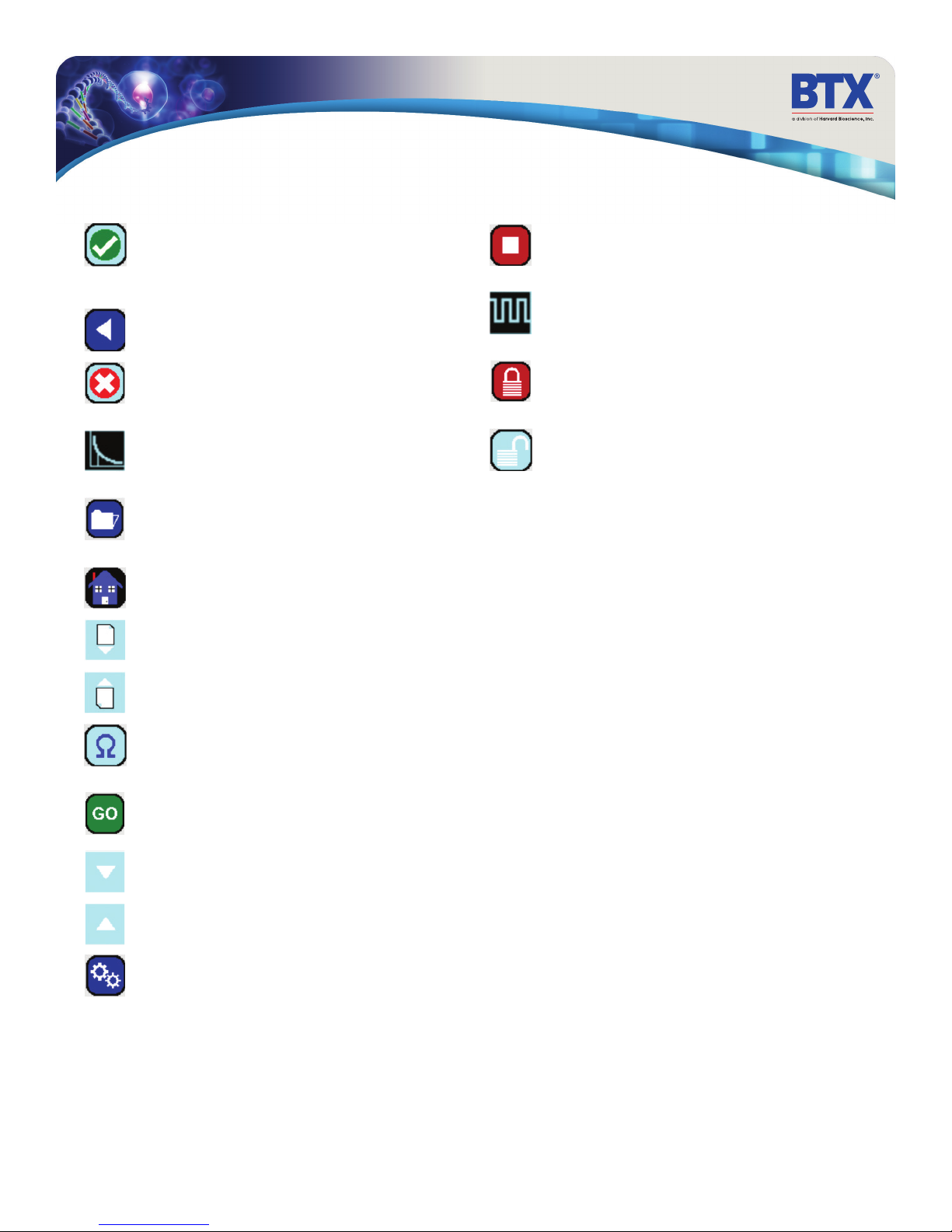
Accept
Used to accept the parameters/settings on a screen and
advance to the next screen in the menu, also used in
place of a double tap on various icons.
Back
Used to go back one screen.
Cancel
Used to cancel any changes/entries on a screen and
return to the previous screen in the menu.
Exponential Decay Wave Indicator
Used to indicate when a protocol utilizes exponential
decay wave pulses.
File Options
Access the File Option menu that is used to save,
rename and delete protocols.
Home/Main Menu
Access Preset Protocols, User Protocols and Settings.
Page Down
Used to page down in a display list.
Page Up
Used to page up in a display list.
Stop Protocol
Used during the pulse delivery sequence to stop the
progress of the protocol.
Square Wave Indicator
Used to indicate when a protocol utilizes square
wave pulses.
Touch Screen Locked
Indicates that the touch screen is currently locked. Press
the icon and enter password to unlock the touch screen.
Touch Screen Unlocked
Indicates that the touch screen is currently unlocked.
Pressing the icon twice will allow the user to password
protect the protocol.
Pre-Pulse Resistance Measurement
Used to measure the resistance of the sample prior to
delivering the DC pulse.
Run Protocol
Used to deliver the pulse protocol to the sample.
Scroll Down
Used to scroll down in a display list.
Scroll Up
Used to scroll up in a display list.
Settings
Access the settings menu used to adjust the following
parameters: Date and Time, Audible Alarms,
Backlighting, and software updates. Displays device
information.
toll free 800.272.2775 • 508.893.8999 • www.btxonline.com
Gemini Series Electroporator User’s Manual
15
Page 16
Software Setup
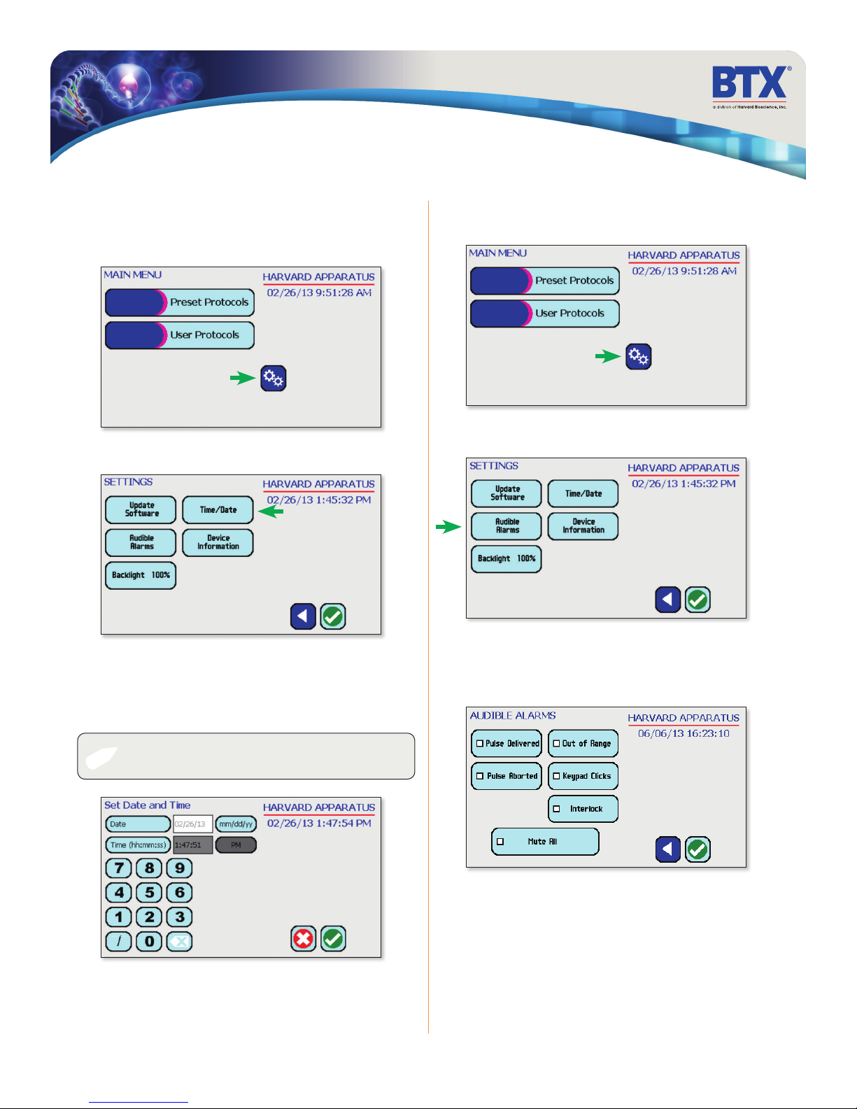
Setting Time/Date
After initializing, the home screen will appear.
Tap the Gears icon
MAINSETTINGSDATE / TIME
Tap Time/Date icon.
Setting Audible Alarm Preferences
On the home screen, tap the Gears icon
Tap Audible Alarms icon.
Tap Date icon and use the keypad to type the date.
Tap Time icon and use the keypad to type the time.
Tap the Green Check icon to save and return to the settings screen.
NOTE: You may change the date and time format by tapping
✐
icons to the right of the given values.
toll free 800.272.2775 • 508.893.8999 • www.btxonline.com
Select preferred audible alarms by tapping the icons to activate
or deactivate.
Tap the Green Check icon to save and return to the settings screen.
AUDIBLE ALARMS
Gemini Series Electroporator User’s Manual
16
Page 17
Software Setup
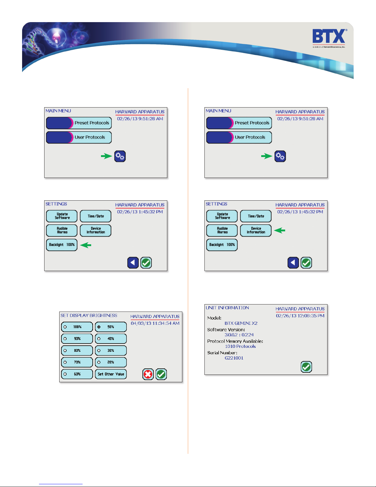
Setting Backlight Preferences
On the home screen, tap the Gears icon
Tap Backlight icon. Tap Device Information icon.
Displaying Device Information
On the home screen, tap the Gears icon.
Select preferred brightness by tapping the icons indicating
% brightness.
Tap the Green Check icon to save and return to the settings screen.
(not shown)
BACKLIGHT
BACKLIGHT - KEYPAD
toll free 800.272.2775 • 508.893.8999 • www.btxonline.com
View device information.
Tap the Green Check icon to return to the settings screen.
INFO
Gemini Series Electroporator User’s Manual
17
Page 18
Preset Protocols
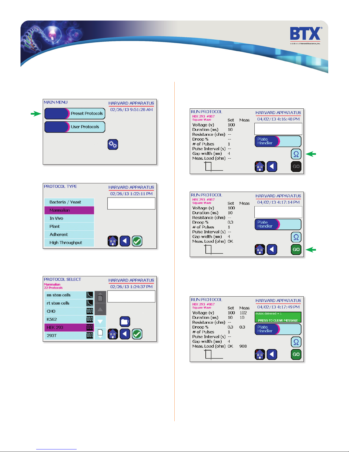
Using Preset Protocols
On the home screen, tap the Preset Protocols icon.
Double tap desired cell type.
PROTOCOL TYPEPROTOCOL SELECT
Using Preset Protocols (continued)
Review parameters.
Tap Omega icon to measure pre pulse load resistance.
RUN
With load measurement OK press the Circle icon to run protocol.
Scroll through available cells.
Double tap desired cells.
Once protocol is complete, data regarding your pulse is displayed
and stored in the systems logs (BTX Gemini X2 only) for future use.
You may continue pulsing, go back to the protocol select screen,
or to the home screen.
toll free 800.272.2775 • 508.893.8999 • www.btxonline.com
Gemini Series Electroporator User’s Manual
18
Page 19
Preset Protocols
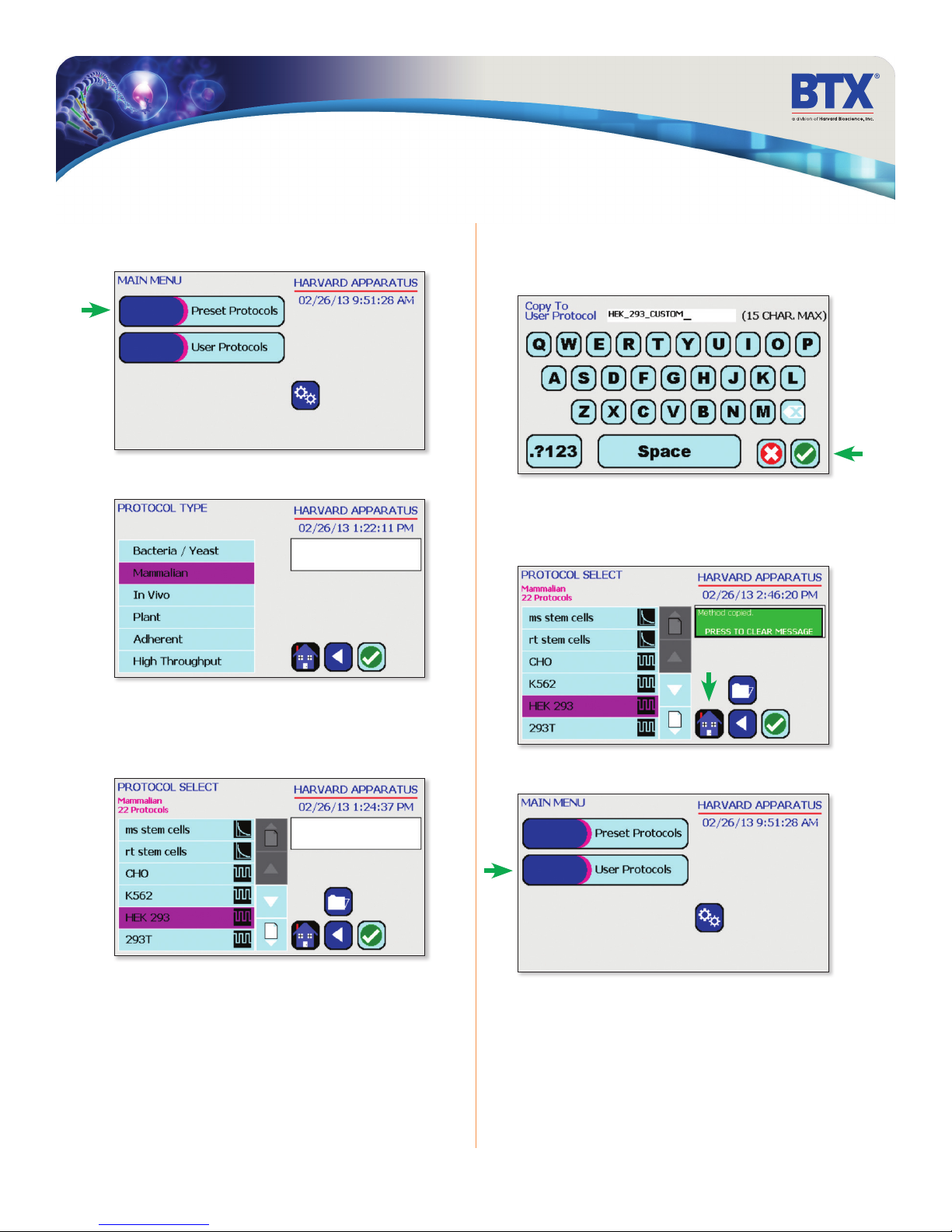
Customizing a Preset Protocol
On the home screen, tap the Preset Protocols icon.
Double tap desired cell type.
Customizing a Preset Protocol (continued)
Use keyboard to name copy of protocol.
Tap the Green Check icon to save.
KEYBOARD
The message board will turn green and alert the user that the
method has been copied.
Tap the Home icon.
Scroll through available cells.
Tap desired cells.
Tap Folder icon.
On the home screen, tap User Protocols icon.
toll free 800.272.2775 • 508.893.8999 • www.btxonline.com
Gemini Series Electroporator User’s Manual
19
Page 20
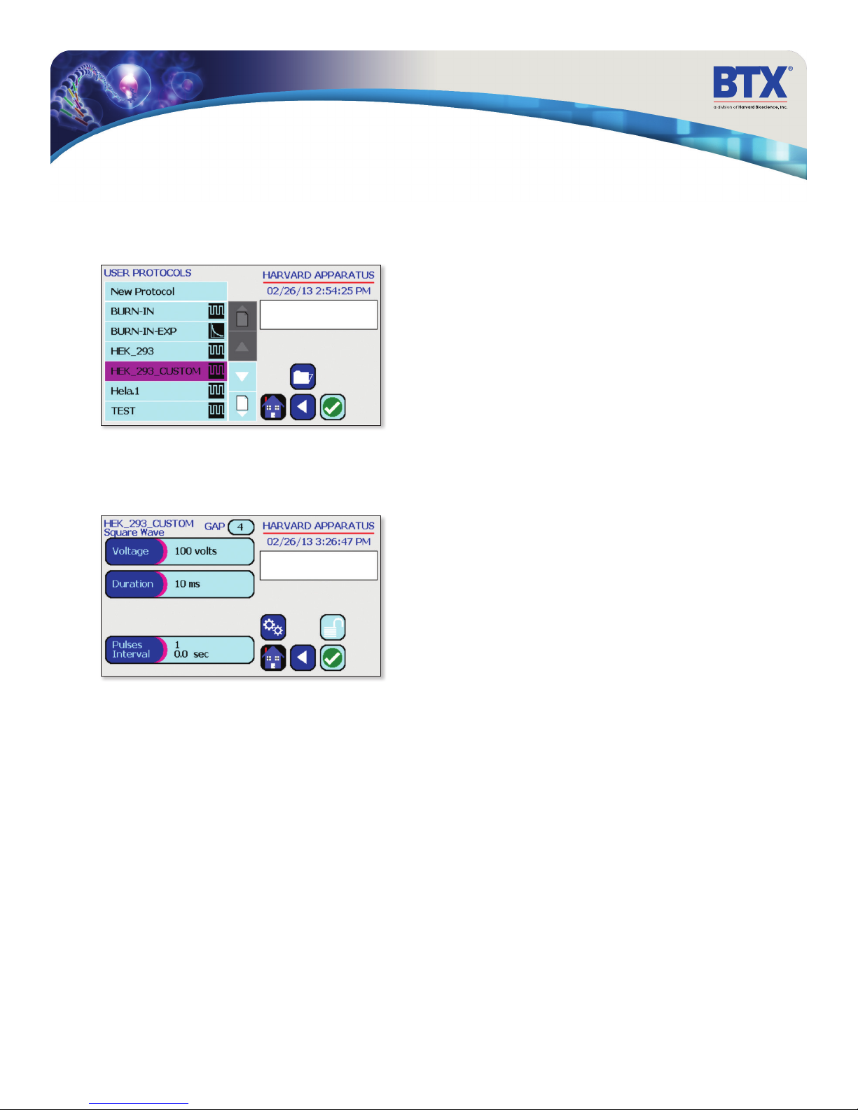
Preset Protocols
Customizing a Preset Protocol (continued)
Scroll through user protocols to locate the newly saved method.
Double tap the newly saved method.
Tap the parameter(s) requiring customization.
Proceed to modify selected parameters.
Tap the Green Check icon to proceed to the run screen.
PROTO EDIT
toll free 800.272.2775 • 508.893.8999 • www.btxonline.com
Gemini Series Electroporator User’s Manual
20
Page 21
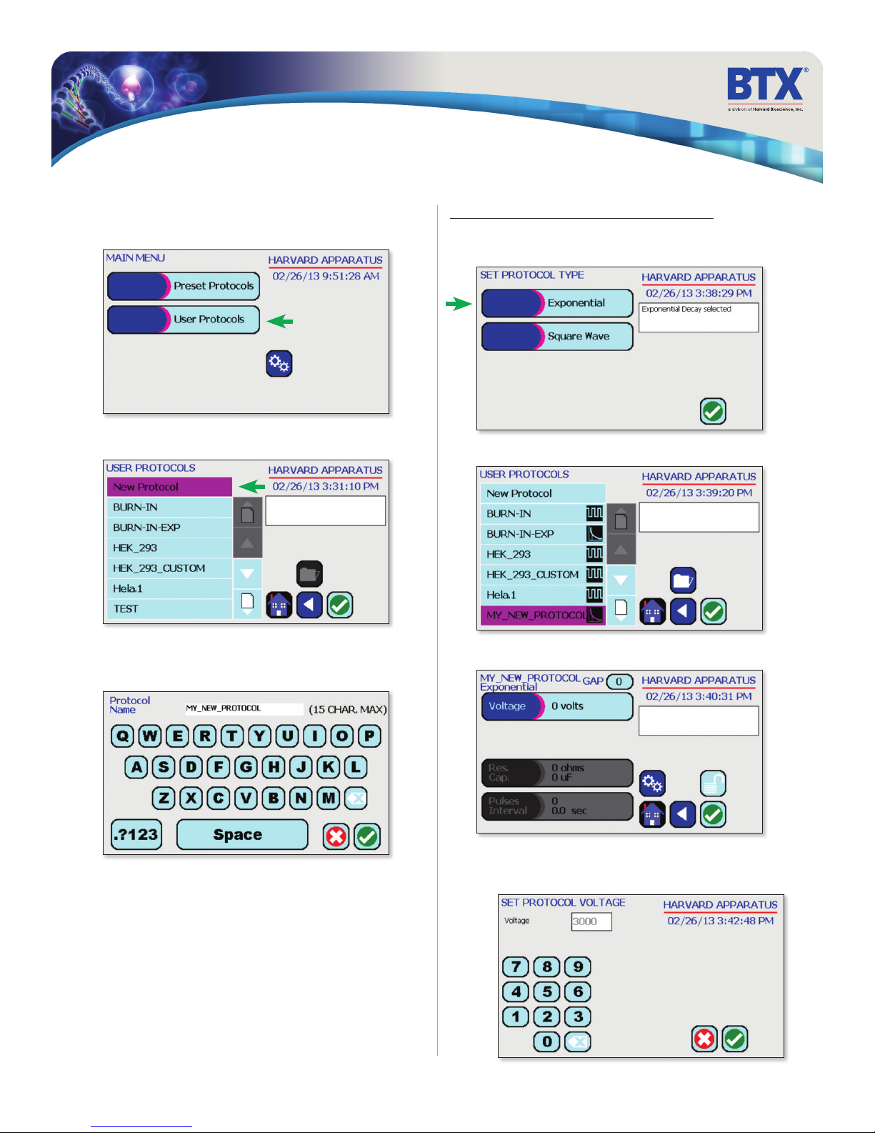
Performing Experiments
Creating New Protocols
On the home screen, tap User Protocols icon.
Double tap New Protocol.
Creating an Exponential Decay Wave Protocol
Tap the Exponential icon.
Tap the Green Check icon to save.
PROTO SET TYPEEDIT SCREEN
Double tap your newly saved protocol.
Use keyboard to name protocol.
Tap the Green Check icon to save.
Tap the Voltage icon.
Use the numeric keypad to set voltage.
Tap the Green Check icon to save.
SET VOLUME
toll free 800.272.2775 • 508.893.8999 • www.btxonline.com
Gemini Series Electroporator User’s Manual
21
Page 22
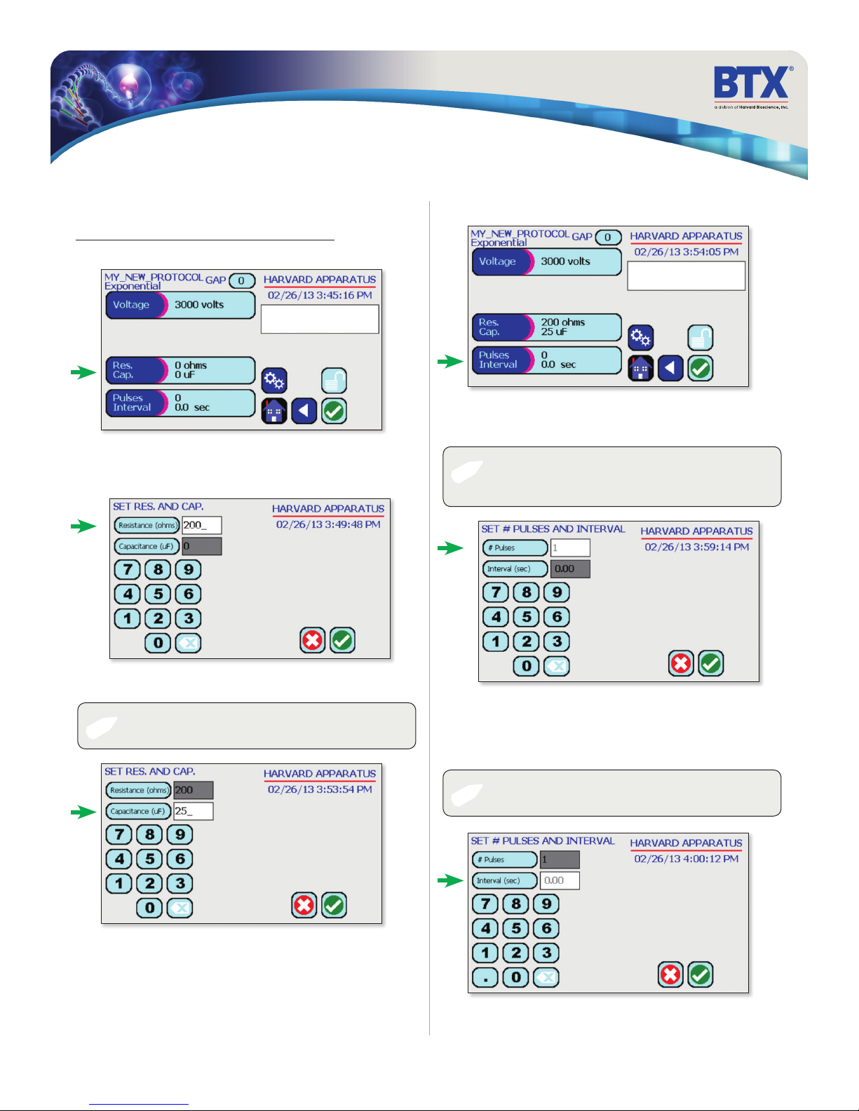
Performing Experiments
Creating New Protocols (continued)
Creating an Exponential Decay Wave Protocol (continued)
Tap the Res. Cap. icon.
Tap the Resistance (ohms) icon.
Use the numeric keypad to set resistance value.
Tap the Pulses Interval icon.
Tap the # Pulses icon.
Use the numeric keypad to set the # of pulses.
NOTE: Only the BTX Gemini X2 can perform multiple pulsing
✐
with Exponential Decay Wave, the BTX Gemini SC cannot
perform multiple pulsing with Exponential decay waves.
SET RES CAP
EDIT SCREEN
Tap the Capacitance (uF) icon.
NOTE: LV and HV mode capacitance values differ. Use the
✐
numeric keypad to set resistance value.
EDIT SCREEN
SET PULSES INTVL
Tap the Interval (sec) icon.
Use the numeric keypad to set the interval between pulses.
Tap the Green Check icon to save.
NOTE: Intervals must only be set when performing
✐
multiple pulsing.
toll free 800.272.2775 • 508.893.8999 • www.btxonline.com
Gemini Series Electroporator User’s Manual
22
Page 23
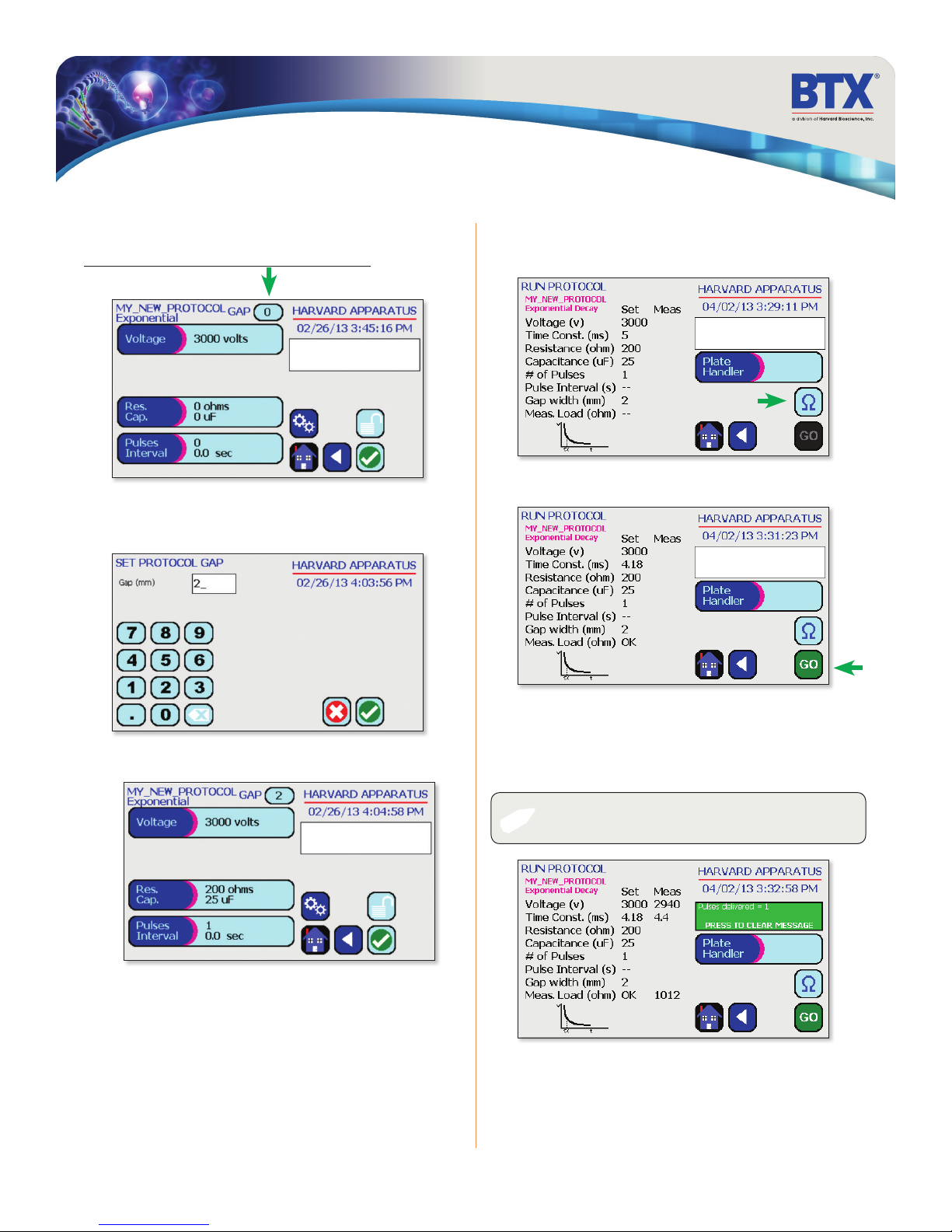
Performing Experiments
Creating New Protocols (continued)
Creating an Exponential Decay Wave Protocol (continued)
Tap the Gap icon.
Use the numeric keypad to set the gap between electrodes.
Tap the Green Check icon to save.
View your protocol.
To run, tap the Omega icon.
With load measurement OK, press the Go icon to run protocol.
Tap the Green Check icon to proceed to the run screen.
EDIT SCREEN
SET PROTO GAP
toll free 800.272.2775 • 508.893.8999 • www.btxonline.com
Once protocol is complete, data regarding your pulse is displayed
and stored in the systems logs (BTX Gemini X
You may continue pulsing, go back to set-up screen, or to the
home screen.
NOTE: See the Protocol Manager user manual for instructions
✐
Gemini Series Electroporator User’s Manual
23
on viewing and downloading log data.
2
only) for future use.
Page 24
Performing Experiments
Creating New Protocols (continued)
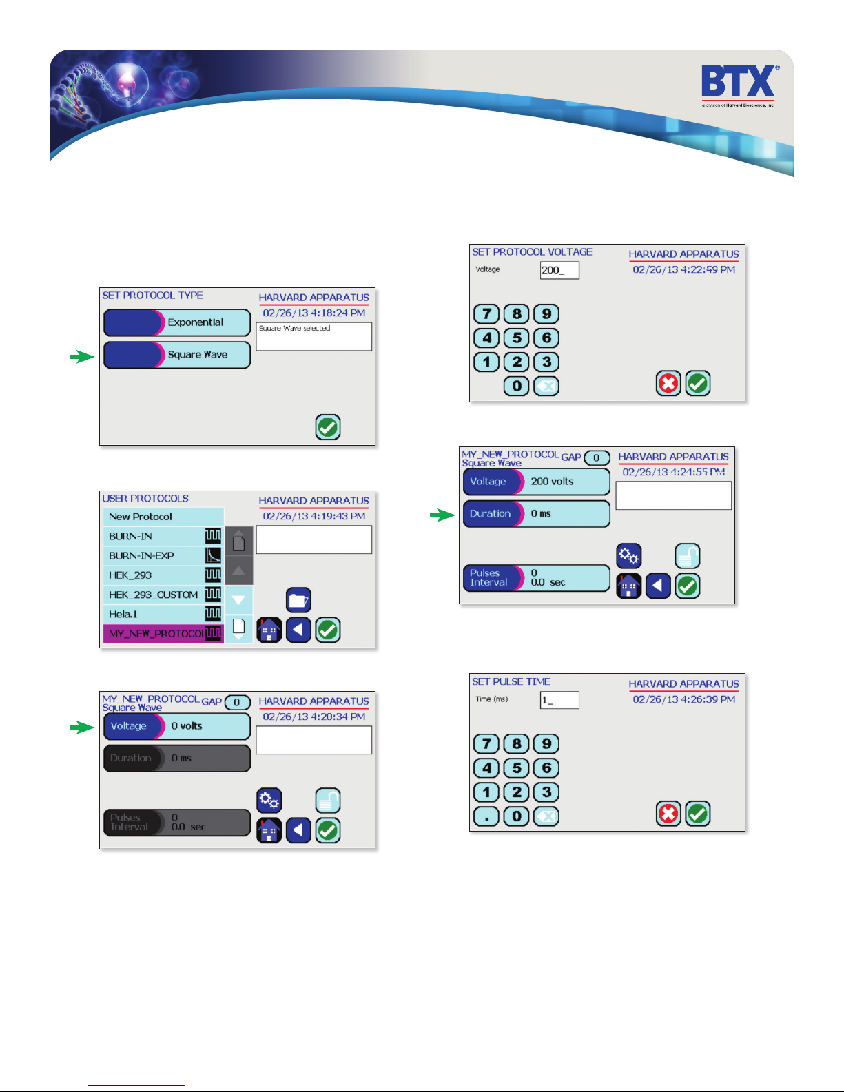
Creating a Square Wave Protocol
Tap the Square Wave icon.
Tap the Green Check icon to save.
Double tap your newly saved protocol.
Use the numeric keypad to set voltage
Tap the Green Check icon to save.
EDIT SCREEN
SET VOLTAGE
Tap the Duration icon.
Tap the Voltage icon.
Use the numeric keypad to set the pulse length.
Tap the Green Check icon to save.
EDIT SCREEN
SET PULSE TIME
toll free 800.272.2775 • 508.893.8999 • www.btxonline.com
Gemini Series Electroporator User’s Manual
24
Page 25
Performing Experiments
Creating New Protocols (continued)
Creating a Square Wave Protocol (continued)
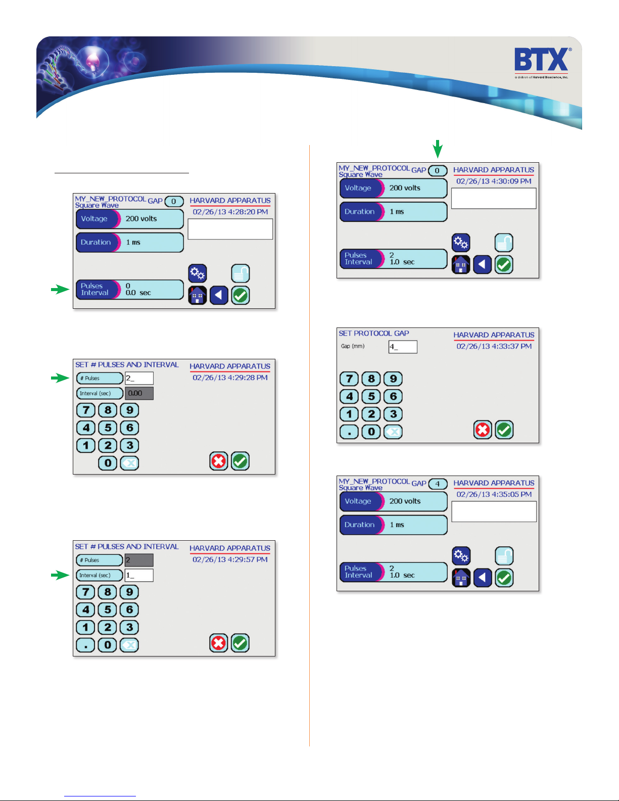
Tap the Pulses Interval icon.
Tap the # Pulses icon.
Use the numeric keypad to set the # of pulses.
Tap the Gap icon
Use the numeric keypad to set the gap between electrodes.
Tap the Green Check icon to save.
EDIT SCREEN
SET PROTO GAP
Tap the Interval (sec) icon.
Use the numeric keypad to set the pulse interval.
Tap the Green Check icon to save.
Tap the Green Check icon to proceed to the run screen.
toll free 800.272.2775 • 508.893.8999 • www.btxonline.com
Gemini Series Electroporator User’s Manual
25
Page 26
Performing Experiments
Creating New Protocols (continued)
Creating a Square Wave Protocol (continued)
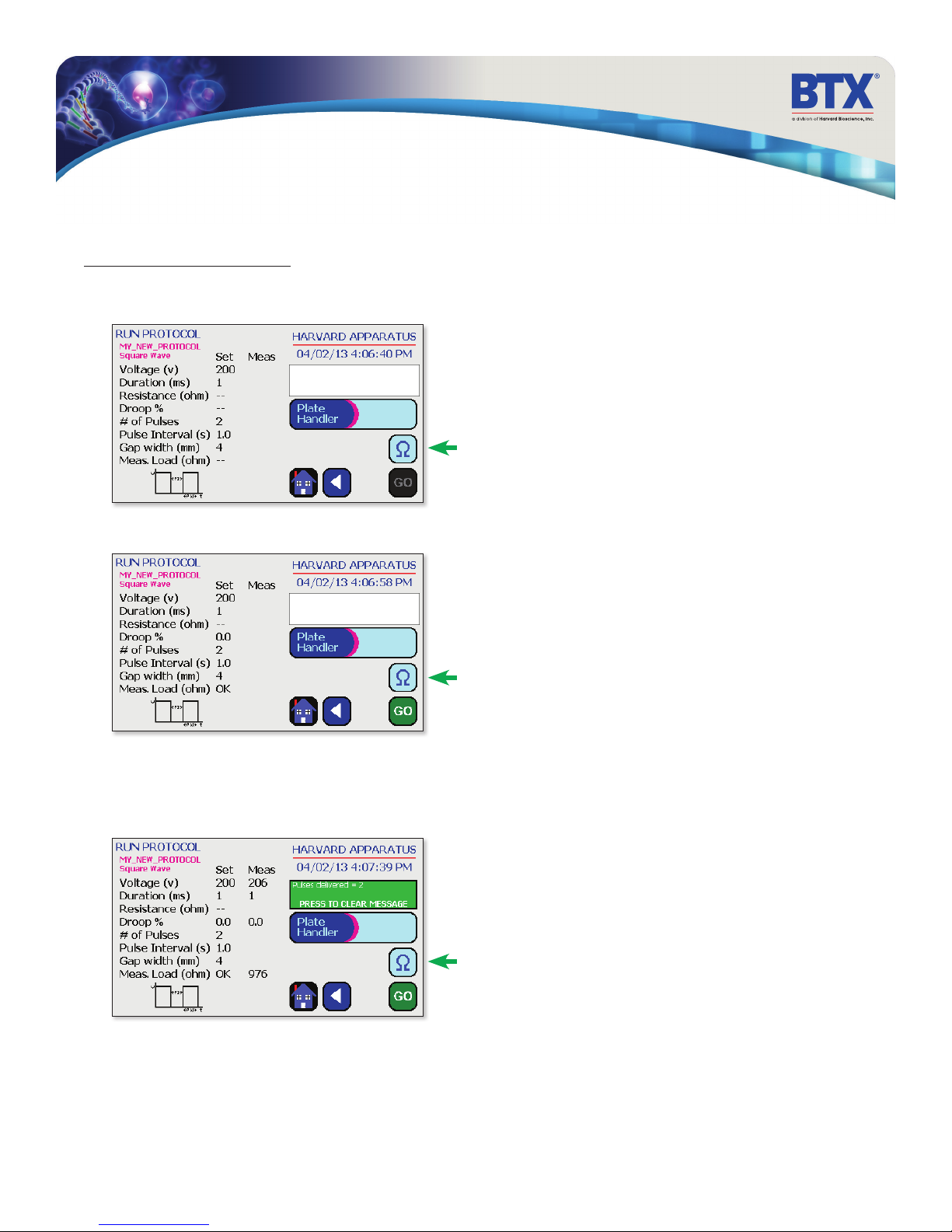
View your protocol.
To run, tap the Omega icon.
With load measurement OK, press the Go icon to run protocol.
Once protocol is complete, data regarding your pulse is displayed
and stored in the systems logs (BTX Gemini X2 only) for future use.
You may continue pulsing, go back to the set-up screen, or to the
home screen.
toll free 800.272.2775 • 508.893.8999 • www.btxonline.com
Gemini Series Electroporator User’s Manual
26
Page 27
Using Specialty Protocols
Using an HT Plate Handler, Gemini X2 only
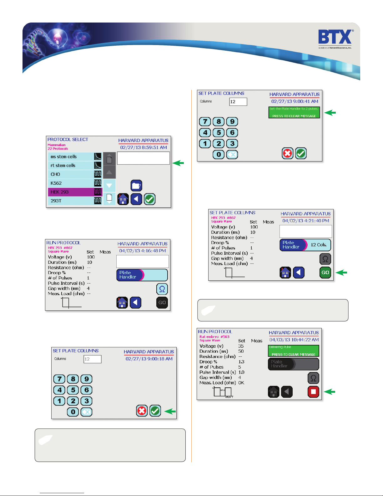
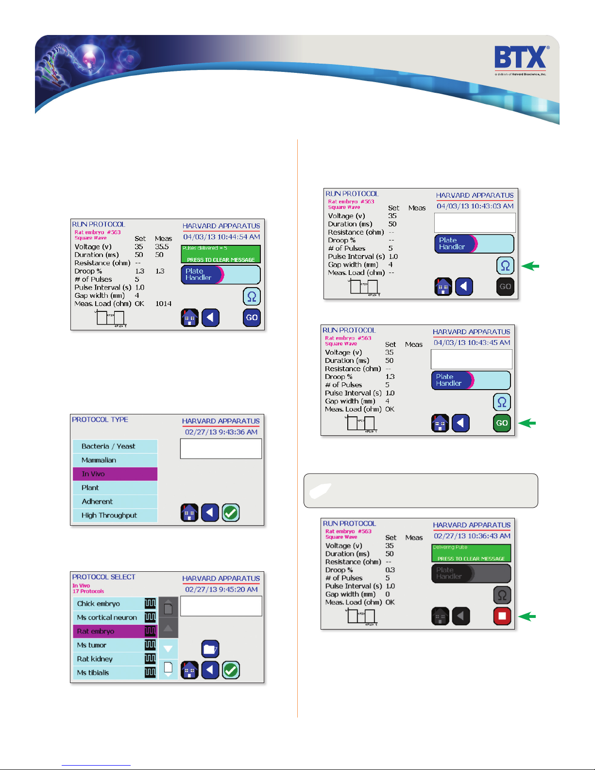
Plug the HT Plate Handler into the front ports of the
BTX Gemini X2.
Scroll through available cells.
Double tap desired cells.
Review parameters.
Tap Plate Handler icon.
Review parameters.
Set the HT plate handler with the correct number of pre-pulse
resistance measurement and DC pulses.
Tap the Go icon to run protocol.
Using the numeric keypad icon, type the number of columns being
pulsed.
Tap the Green Check icon to save.
EDIT SCREEN
SET PLATE COLS
NOTE: Note the message box. It will indicate how many
✐
pulses should be set in the HT plate handler. This number will
be a combination of both pre-pulse resistance measurements
and DC pulses.
toll free 800.272.2775 • 508.893.8999 • www.btxonline.com
The Square icon can be used to stop the protocol at any time.
NOTE: Generator will display readings of the 1st and last pulse
✐
Gemini Series Electroporator User’s Manual
27
of each column.
Page 28
Using Specialty Protocols
Using an HT Plate Handler, Gemini X2 only
(continued)
Once protocol is complete, data regarding your pulse is displayed
and stored in the systems logs for future use.
You may continue pulsing, go back to the settings screen or
protocol select screen, or to the home screen.
Using Specialty Electrodes, Gemini X2 Only
Plug the specialty electrodes into the front ports of the
BTX Gemini X2
Scroll through available protocols.
Double tap desired selection.
Review parameters.
Position electrodes on area being electroporated.
To run tap the Omega icon.
With load measurement OK, press the Go icon to run protocol.
Scroll through available cells.
Double tap desired cells.
toll free 800.272.2775 • 508.893.8999 • www.btxonline.com
While the pulse is being delivered, the Square icon can be used to
stop the protocol at any time.
NOTE: Generator will display readings after each pulse.
✐
Gemini Series Electroporator User’s Manual
28
Page 29
Using Speciality Protocols
Using Specialty Electrodes, Gemini X2 Only
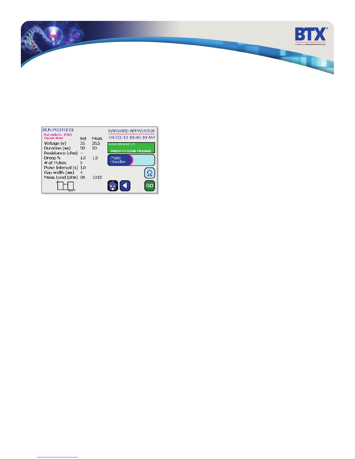
Once protocol is complete, data regarding your pulse is displayed
and stored in the systems logs for future use.
You may continue pulsing, go back to the settings screen or the
protocol select screen, or to the home screen.
toll free 800.272.2775 • 508.893.8999 • www.btxonline.com
Gemini Series Electroporator User’s Manual
29
Page 30
Managing Protocols
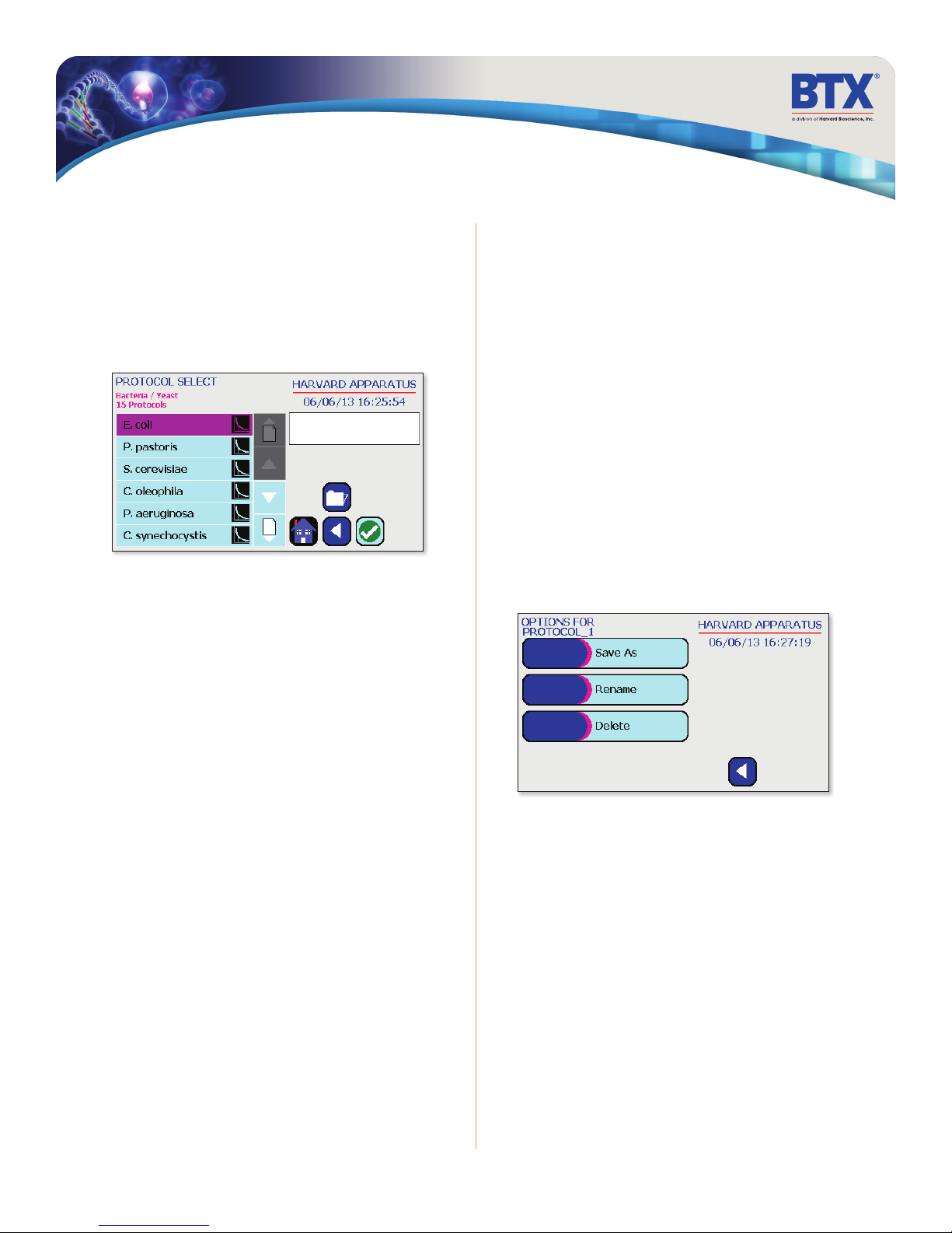
All Preset and User-Defined Protocols are stored in the Protocol List
for ongoing use. Over time, you may want to manage previously
created Protocols to keep your Protocol List easy to navigate.
In addition, the BTX Gemini X2 allows you to export Protocol
information to an externally connected generator or to a computer
that will be used to control operation. This section of the Guide
describes the file management facilities available on the BTX
Gemini X2.
Saving a Copy of a Protocol
Follow these instructions to save a copy of a Protocol under a new
name:
1. From Protocol Configuration screen, choose the
Protocol Name button to enter the Mode Selection
screen.
2. From the list of available Protocols, select (press once) the
Protocol you want to save a copy of, then choose the
File Options button to enter the File Options screen.
3. Choose Save As/Copy to access the Protocol Name Entry
screen. The current Protocol Name will be displayed in the
text entry box.
4. On the Protocol Name screen, type the new name for your
Protocol using the onscreen keyboard. Choose the Symbols/
Numbers button (.?123) to display the list of available
numbers and symbols that can be included in the Protocol
Name. To switch the keyboard back to letters mode, choose
the Letters button (ABC). [15 characters maximum]
5. When finished entering the new Protocol Name, choose
Accept to save your changes and return to the File Options
screen.
6. Choose BACK to return to the Mode Selection screen
Renaming a Protocol
Follow these instructions to rename a previously saved user
protocol:
1. From the Protocol Configuration screen, choose the
Protocol Name button to enter the Protocol Mode screen.
2. From the list of available Protocols, select (press once) the
Protocol you want to rename, then choose the File Options
button to enter the File Options screen.
3. Choose Rename Protocol to access the Protocol Name
Entry screen. The current Protocol Name will be displayed in
the text entry box.
4. On the Protocol Name screen, type the new name for your
Protocol using the onscreen keyboard. Choose the Symbols/
Numbers button (.?123) to display the list of available
numbers and symbols that can be included in the Protocol
Name. To switch the keyboard back to letters mode, choose
the Letters button (ABC). [15 characters maximum]
5. When finished entering the new Protocol Name, choose
Accept to save your changes and return to the File Options
screen.
6. Choose Back to return to the Protocol.
FILE OPTIONS
toll free 800.272.2775 • 508.893.8999 • www.btxonline.com
Gemini Series Electroporator User’s Manual
30
Page 31
Managing Protocols
Deleting a Protocol
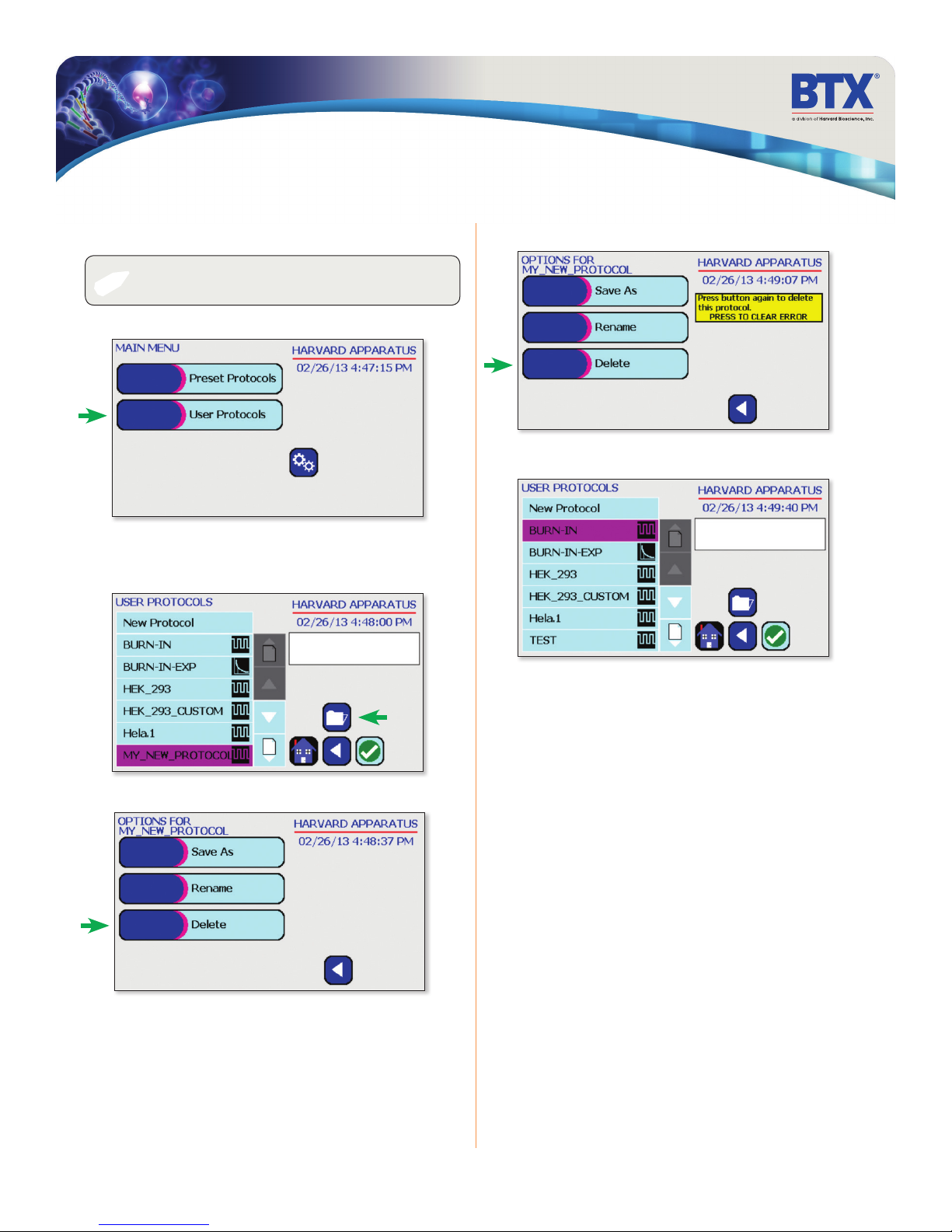
NOTE: Preset protocols cannot be deleted.
✐
On the home screen, tap the User Protocols icon.
Tap the protocol you wish to delete.
Tap Folder icon.
Confirm delete by tapping the Delete icon again.
Protocol has been removed from the menu.
Tap Delete icon.
toll free 800.272.2775 • 508.893.8999 • www.btxonline.com
Gemini Series Electroporator User’s Manual
31
Page 32
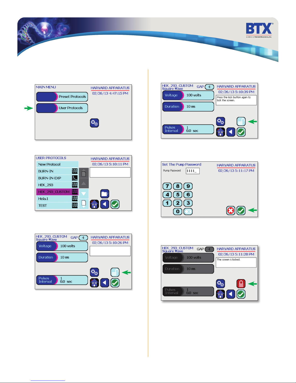
Managing Protocols
Password Protecting a Protocol
On the home screen, tap the User Protocols icon.
Double tap protocol you wish to password protect.
Confirm password protection by tapping the Open Lock
icon again.
Use the numeric keypad to set the password.
Tap the Green Check icon to save.
LOCK
View the protocol.
Tap the Open Lock icon.
The protocol is now locked against modifications.
To Unlock press the lock icon. Type in the password then Tap the
Green Check icon.
toll free 800.272.2775 • 508.893.8999 • www.btxonline.com
Gemini Series Electroporator User’s Manual
32
Page 33
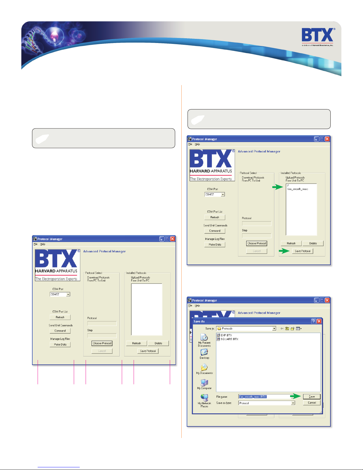
Protocol Manager Software
Installation
Insert the generator CD into the CDROM, a file containing the
CD’s contents will open automatically. Navigate to the Protocol
Manager folder, under Applications. Right click on “Protocol
Manager”. Select “Send To” then “Desktop” to create a shortcut
on your desktop.
NOTE: Compatible with Windows XP & Windows 7.
✐
1. Connect the generator to the PC using a USB cable.
2. Turn generator on.
3. Start Protocol Manager.
4. Select the proper COM port.
Overview
Protocol Manager allows the user to:
• Upload protocols from the Gemini X2 generator to a PC.
• Download protocols from PC to the Gemini X2 generator.
• Upload log files from the Gemini X2 generator to PC.
Upload– Generator to PC
1. Select Protocol(s)
2. Click ‘Save Protocol’
NOTE: Hit ‘Refresh’ to update the list after creating or editing
✐
protocols on the Gemini X2 generator.
Log File
Control
PC to Generator
Protocol Control
toll free 800.272.2775 • 508.893.8999 • www.btxonline.com
3. Select the drive and folder location
4. Click ‘Save’
Generator to PC
Protocol Control
Gemini Series Electroporator User’s Manual
33
Page 34
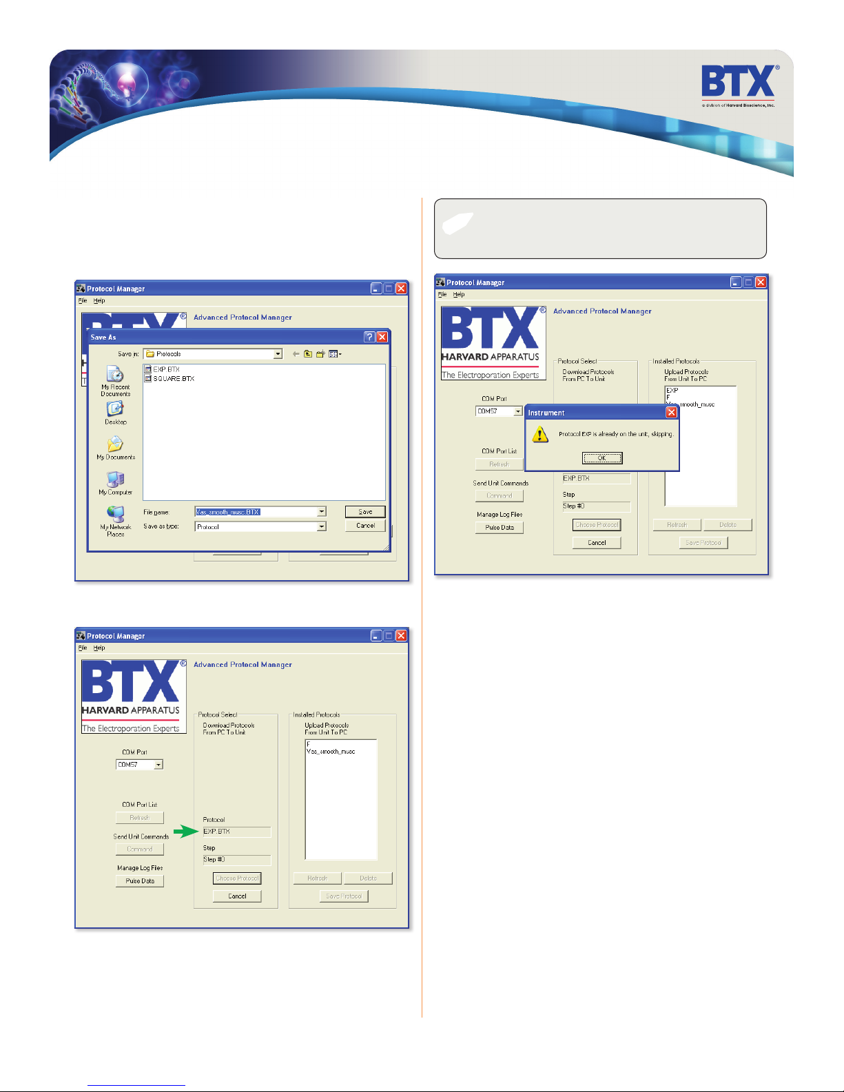
Protocol Manager Software
Download - PC to Generator
1. Click ‘Choose Protocol’
2. Select Protocol(s) to download
3. Click ‘Open’
✐
NOTE: If a protocol already exists on the Gemini X2 generator,
Protocol Manager will not overwrite the le if you attempt to
re-download it.
4. Protocol name being downloaded is shown
toll free 800.272.2775 • 508.893.8999 • www.btxonline.com
Gemini Series Electroporator User’s Manual
34
Page 35
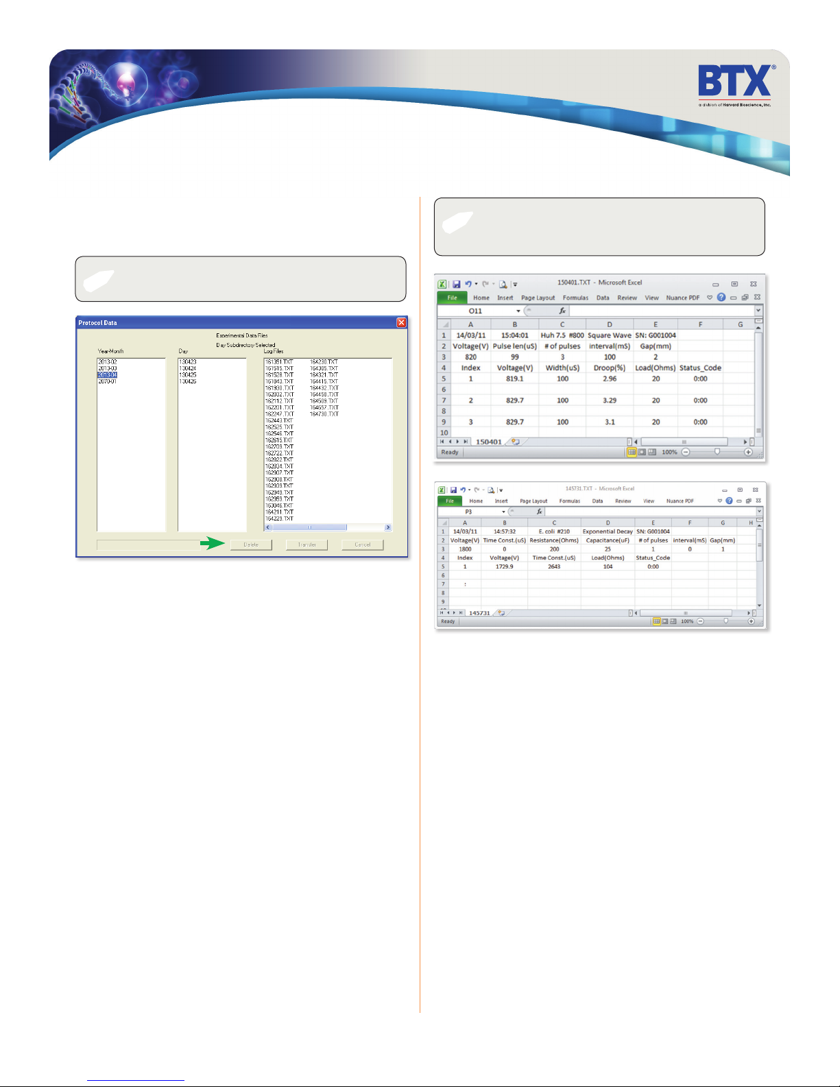
Protocol Manager Software
Upload Log Files
1. On the main screen, click ‘Pulse Data’
2. Select your desired files or folders and then click ‘Transfer’.
NOTE: Files should be backed up periodically. The generator’s
✐
3. Select the drive or folder location.
SD card can store up to approximately 100,000 les.
✐
NOTE: Log Files are saved as a tab delimited text le. They
can be opened with any common text editor like Notepad or by
using spreadsheet software such as Excel.
Troubleshooting Protocol Manager
1. Do not upload/download Protocols while generator is
running. Program works best while generator is idle on
Protocol setup screen.
2. Order of Operations:
A. Connect USB.
B. Turn generator on.
C. Start Protocol Manager program.
toll free 800.272.2775 • 508.893.8999 • www.btxonline.com
Gemini Series Electroporator User’s Manual
35
Page 36
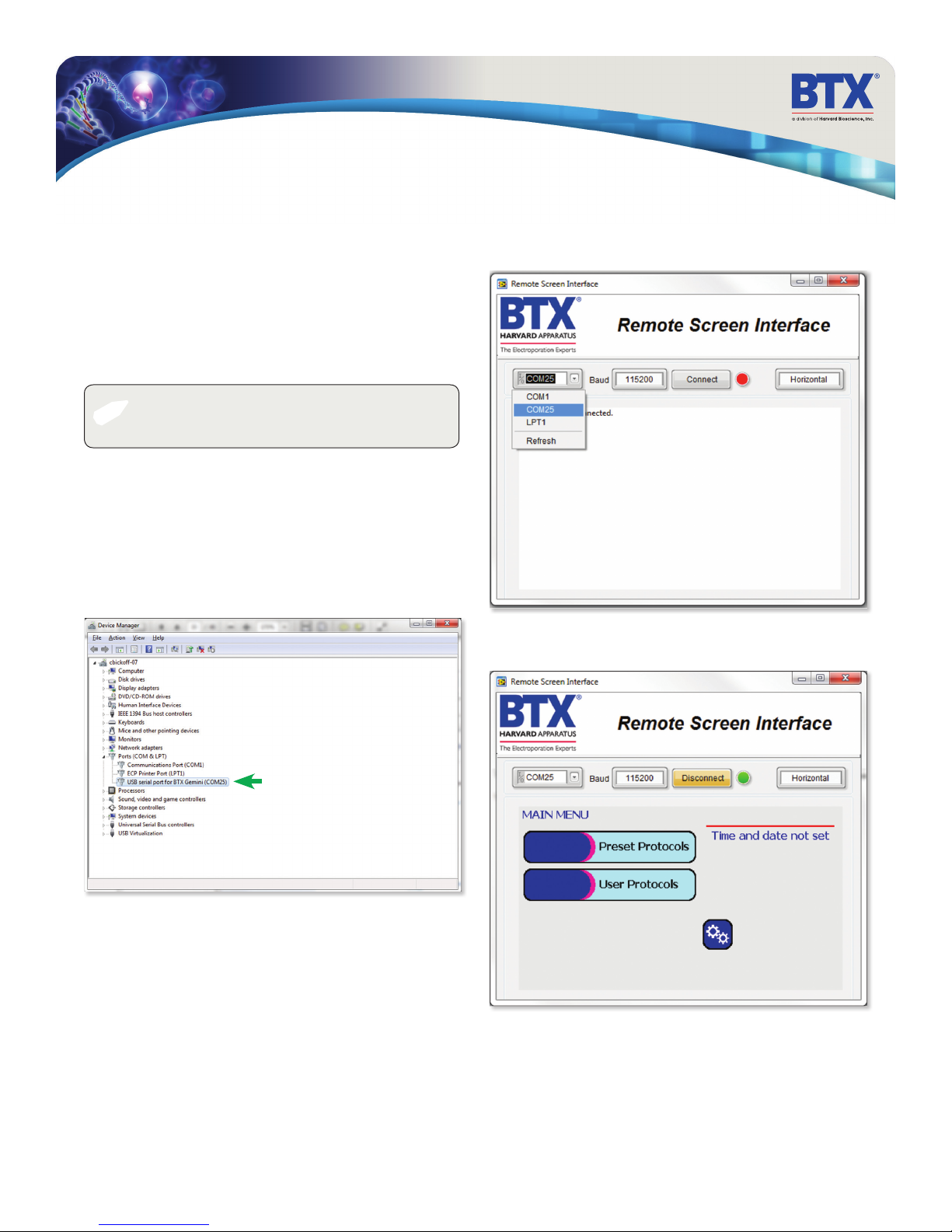
Remote Control Software
Installation
Insert the generator CD into the CDROM. A file containing the
CD’s contents will open automatically. Navigate to the Remote
Screen Interface folder, and then to the Remote Screen
Interface Support Files Installer folder. Run the “setup.exe”
file. Follow the instructions provided on the installation screens.
After the installation is complete, copy the folder Remote Screen
Interface Application from the CD onto the PC in a location of
your choice.
NOTE: during the installation, it will ask you to provide a
✐
Overview
Remote Screen Interface allows you to control the Gemini remotely.
When you click on the computer screen, you control the generator.
While the Gemini generator is connected to the computer via USB,
open the Control Panel and select System and Security, and then
System. Click Device Manager on the left hand menu. Under
Ports, search for the “USB serial port for BTX Gemini.” This will show
the COM Port to which the generator is connected, as shown below.
location to install your application les. There is a known issue
with this installer where it will not actually create this directory.
Once the COM port is known, open the Remote Screen Interface
application. Choose the correct COM port and click Connect.
You should now be able to control your Gemini
generator remotely.
toll free 800.272.2775 • 508.893.8999 • www.btxonline.com
Gemini Series Electroporator User’s Manual
36
Page 37
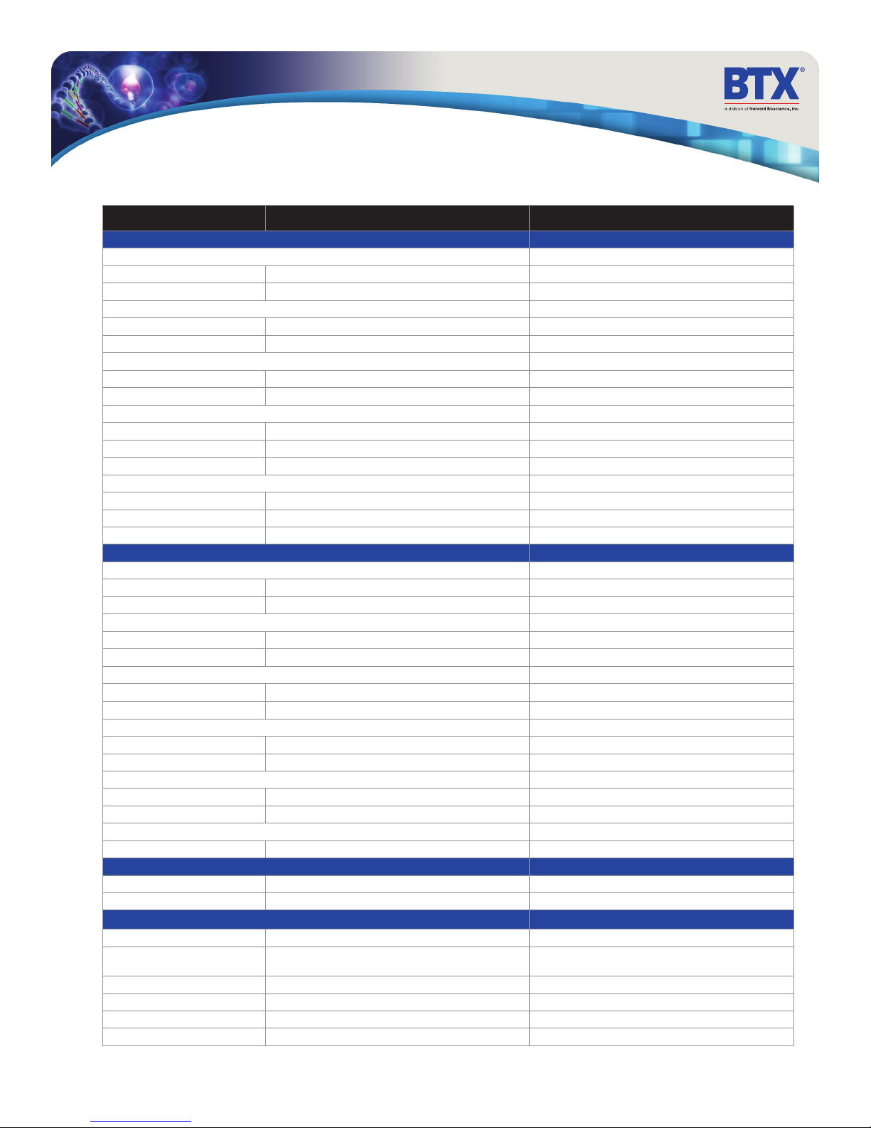
Generator Specifications
Generator Specifications Gemini X2 Gemini SC
Square Wave Pulse Ranges
Voltage Range
LV Mode
HV Mode
Voltage Accuracy
LV Mode
HV Mode
Pulse Length Range
LV Mode
HV Mode
Multiple Pulsing
LV Mode
HV Mode
Pulse Interval
Capacitance in µF
LV Mode
HV Mode
Voltage Droop
Exponential Decay Pulse Ranges
Voltage Range
LV Mode
HV Mode
Voltage Accuracy
LV Mode
HV Mode
Time Constant Range
LV Mode
HV Mode
Multiple Pulsing
Multiple Pulsing
Pulse Interval
Capacitance in µF
LV Mode
HV Mode
Available Internal Resistance Selections
All Modes
Sample Resistance (Load) Exponential Decay or Square
LV Mode
HV Mode
Other Specifications
Charging Time
Monitoring
Display
Controls
Programmability
Arc Control
5-500 in 1 V steps 10-500 V in 5 V steps
505-3000 in 5 V steps 510-3000 in 10 V steps
5% 5%
5% 5%
10-999 µs in 1 µs step, 1-999 ms in 1 ms step 0.05-10 ms in 0.05 ms steps, 10-100 ms in 1 ms step
10-600 µs / 1 µs step 50 µs-5 ms in 50 µs steps
1-10 pulses per sample 1 to 10
1-3 pulses per sample 1 to 2
0.1 s to 10 s 0.1 s to 10 s
3775 µF 3775 µF
85 µF 85 µF
20% Load < 1 K Ω, 10% Load > 1 K Ω 20% Load < 1 K Ω, 10% Load > 1 K Ω
5-500 in 1 V steps 10-500 in 5 V steps
505-3000 in 5 V steps 510-3000 / 10 V steps
5% 5%
5% 5%
1 ms to 5.158 s 1.25 ms to 3.275 s / 1.25 ms
0.5 ms to 133.875 ms 0.5 ms to 50 ms / 0.5 ms
1 to 2 depending on device’s current amplitude limit No
5 to 30 s N/A
25-3275 µF in 25 µF steps 25-3275 µF in 25 µF steps
10, 25, 35, 50, 60, 75, 85 µF 10, 25, 50 µF
LV 25-1575 Ω in25 Ω steps, HV 50-1575 Ω in 25 Ω steps 50-1000 Ω in 50 Ω steps
PL ≤ 100ms, load ≥ 8-9 Ω, PL >100ms, load ≥100 Ω Load ≥ 10 Ω
Load ≥ 40 Ω 510-2500 Load ≥ 20 Ω, 2500 to 3000 V, Load ≥ 600 Ω
LV < 7 s, HV < 4 s LV < 7 s, HV < 4 s
Pulse Voltage, Width, Droop % and Sample Resis-
tance
4.3 in color display 4.3 in color display
Touch Screen Touch Screen
Storage over 1000 Protocols Storage over 1000 Protocols
Yes Yes
Pulse Voltage, Width, Droop % and Sample Resistance
toll free 800.272.2775 • 508.893.8999 • www.btxonline.com
Gemini Series Electroporator User’s Manual
37
Page 38
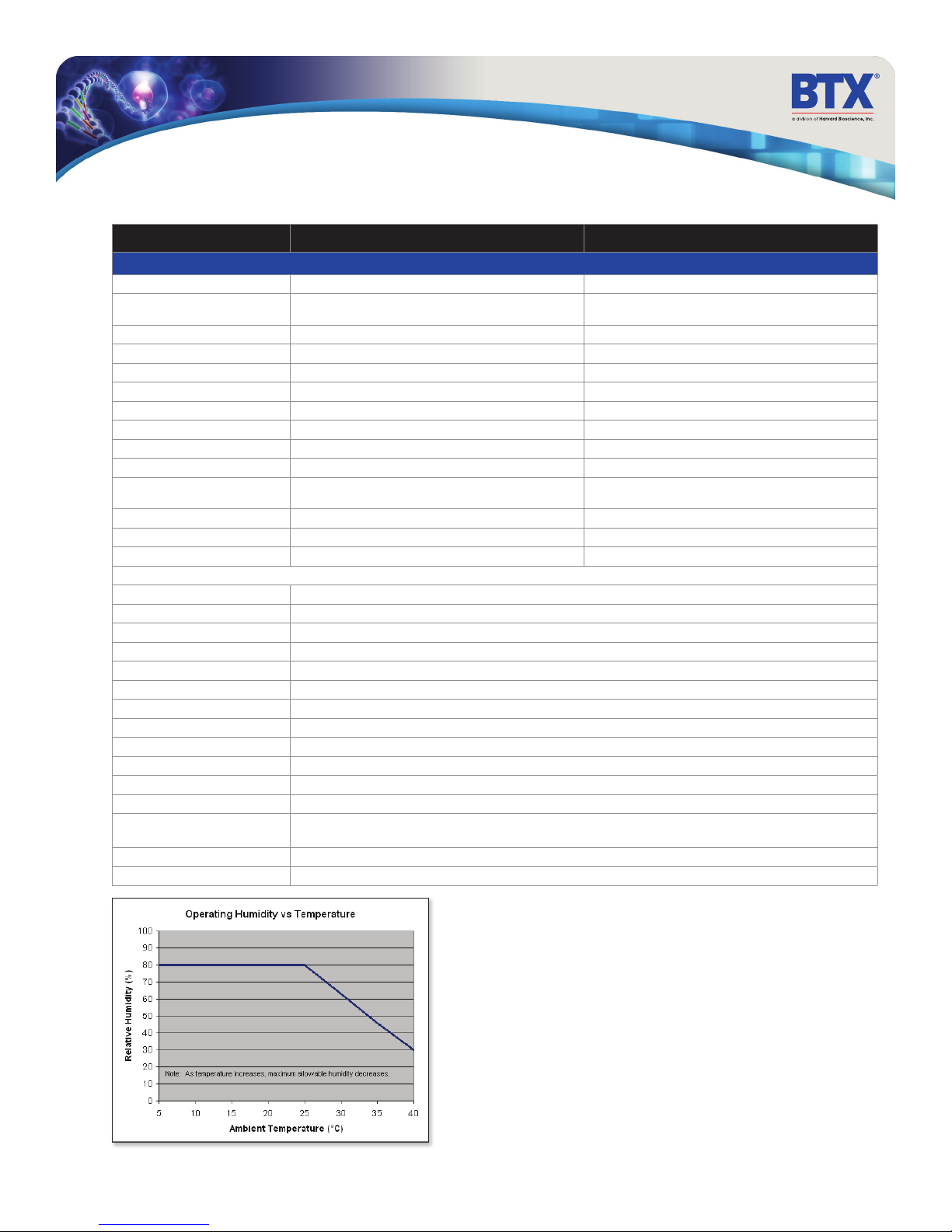
Generator Specifications
Generator Specifications (V7) Gemini X2 Gemini SC
Other Spcifications (continued)
Interlock Switches Ye s Ye s
Pre-Pulse Sample resistance
check
Pulse Over Current Protection Ye s Yes
PC control Ye s No
PC communications Ye s No
Log Report Ye s No
Remote Operation Ye s No
Foot Switch Control Ye s No
Power Ratings 35 W idle and 350 W pulsing 35W idle and 350 W pulsing
Input Voltage ratings 100 to 240 VAC 100 to 240 VAC
CE, ETL Marking, CB Scheme,
EuRoHS
Dimensions (H x W x D) inches 12.75 x 11.25 x 8.5 12.75 x 11.25 x 8.5
Weight ~16 lb ~16 lb
Warranty 2 years 1 year
Atmospheric Specifications
Operating Temperature 4˚C to 40˚C (40˚F to 104˚F)
Storage Temperature -10˚C to 70˚C (14˚F to 158˚F)
Operating Humidity See Chart Below
Storage Humidity 20% to 80% RH, non condensing
Mode of Operation Continuous
Classification Class I
Pollution Degree 1
Installation Category II
Supplier Name BTX
Supplier Address 84 October Hill Rd., Holliston, MA 01746
Supplier Phone Number 508-893-8999
Regulatory Certifications CE, ETL (UL, CSA), WEEE, EU RoHS & CB Scheme
Safety Declarations ANSI/UL 61010-1 ; CAN/CSA C22.2 No. 61010-1;
EMC Declarations IEC 61326-1
FCC 47 CFR Part 15 B
Ye s Ye s
Ye s Ye s
IEC 61010-1; CENELEC EN 61010-1; CB
toll free 800.272.2775 • 508.893.8999 • www.btxonline.com
Gemini Series Electroporator User’s Manual
38
Page 39
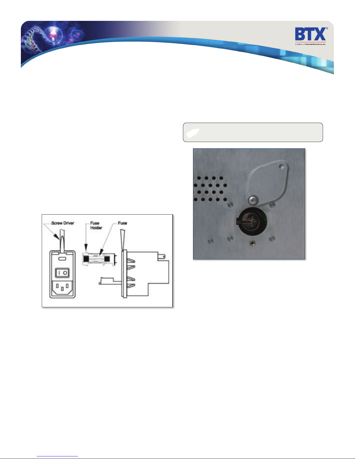
Maintenance
The BTX Gemini Twin Wave Series generators require no special
maintenance other than keeping them clean.
To clean the exterior surfaces, use a lint-free cloth to remove loose
dust. Use care to avoid scratching the clear display window. For
more efficient cleaning, use a soft cloth dampened (not soaked)
with an aqueous solution of 75% isopropyl alcohol, or a mild
detergent.
Fuse Replacement
Key Information
1. Make sure the power cord is disconnected from the main
supply before servicing the fuse.
2. Use only Type 3AG, 1/4 x 11/4 in, 5 amp, 250 volt; Type T
(time delay) fuses.
Turn off power and remove power cord from power module.
Use a straight blade screw-driver to pry open the access door.
Remove the fuse holder and then remove the fuses from this
holder as shown in figure below. Replace fuses, and then replace
the fuse holder.
Battery Replacement
1. Remove screw and swing cover to the side.
2. Slide battery out from under clip.
3. Install Lithium Coin Battery: 3V, 16mm CR1620 by sliding
under clip with positive side facing out.
CAUTION: Use only same type and rated battery. Observe
✐
polarity when installing.
toll free 800.272.2775 • 508.893.8999 • www.btxonline.com
Gemini Series Electroporator User’s Manual
39
Page 40
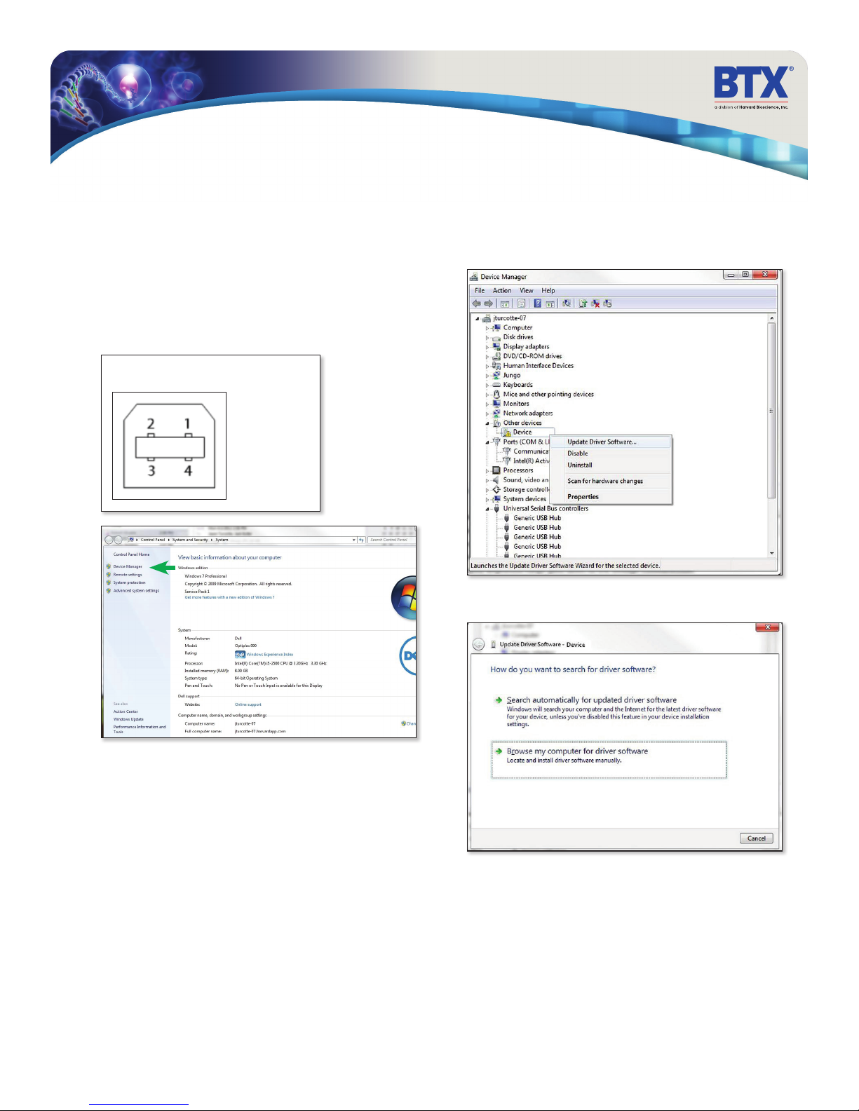
Upgrading Gemini Series Software
USB Virtual Commport Driver Installation
When you connect the BTX Gemini X2 to a computer via USB
for the first time, Windows will seek to install a driver for
communication. The following section details the installation of
the Virtual CommPort Driver supplied with the BTX Gemini X2.
1. Connect the Gemini X2 generator to the computer via USB.
Open the control panel and select System and Security
and then System. Click Device Manager on the left hand
menu.
Mating Face
Pin # Signal
1 +5V
2 - Data
3 + Data
4 GND
2. Two Flash update applications will be displayed in the device
manager, under Other Devices. Right click on either of the
flash update applications and select Update Driver
Software.
3. Select Browse my computer for driver software
toll free 800.272.2775 • 508.893.8999 • www.btxonline.com
Gemini Series Electroporator User’s Manual
40
Page 41
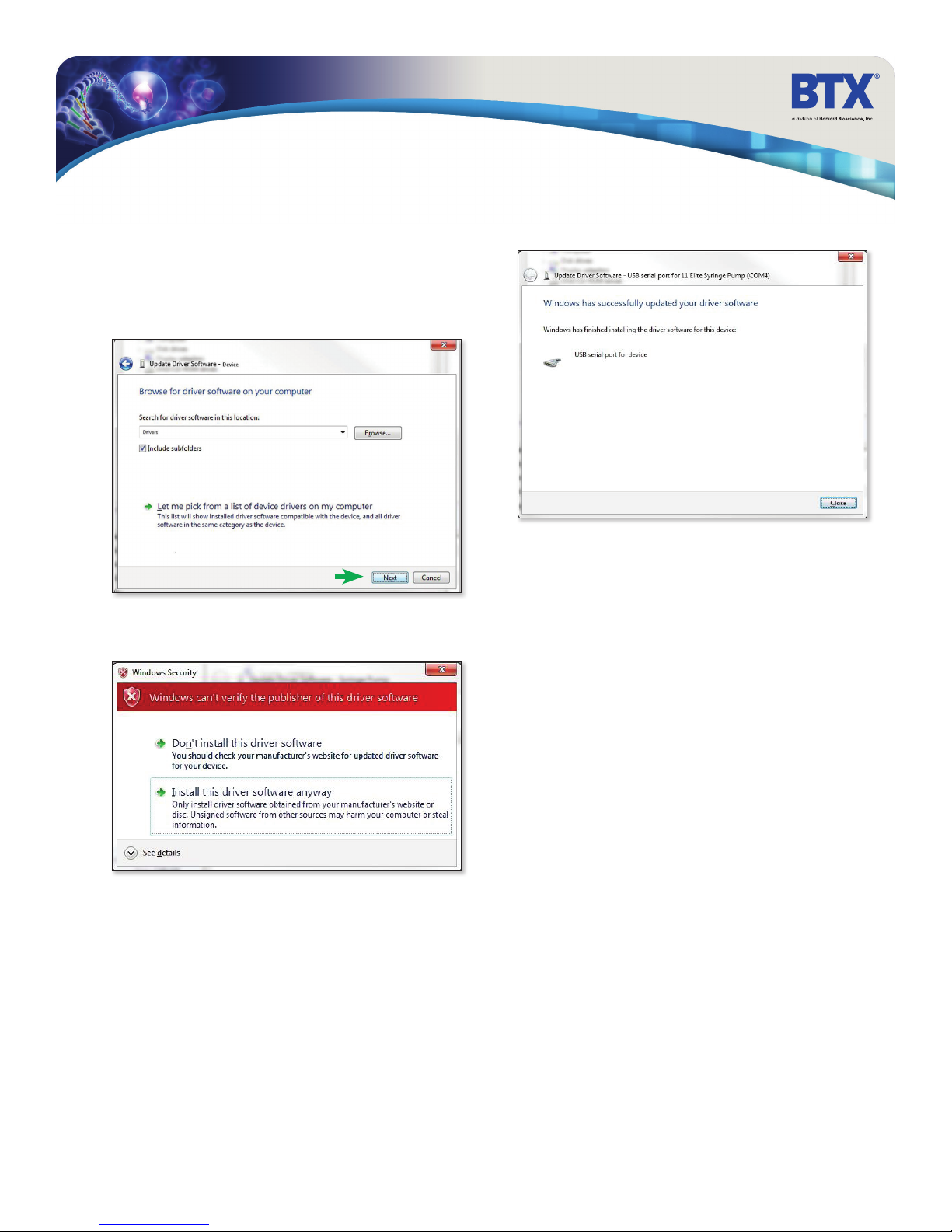
Upgrading Gemini Series Software
USB Virtual Commport Driver Installation
(continued)
4. Click Browse and navigate to the generator drivers folder
located on the CD supplied with the generator. Select the file
BTX USB-CDC.inf. Make sure the Include Subfolders box
is checked and then click Next.
5. If a warning message regarding the driver publisher is
displayed, choose Install this driver software anyway.
6. Click Close after the software has been successfully installed.
toll free 800.272.2775 • 508.893.8999 • www.btxonline.com
Gemini Series Electroporator User’s Manual
41
Page 42
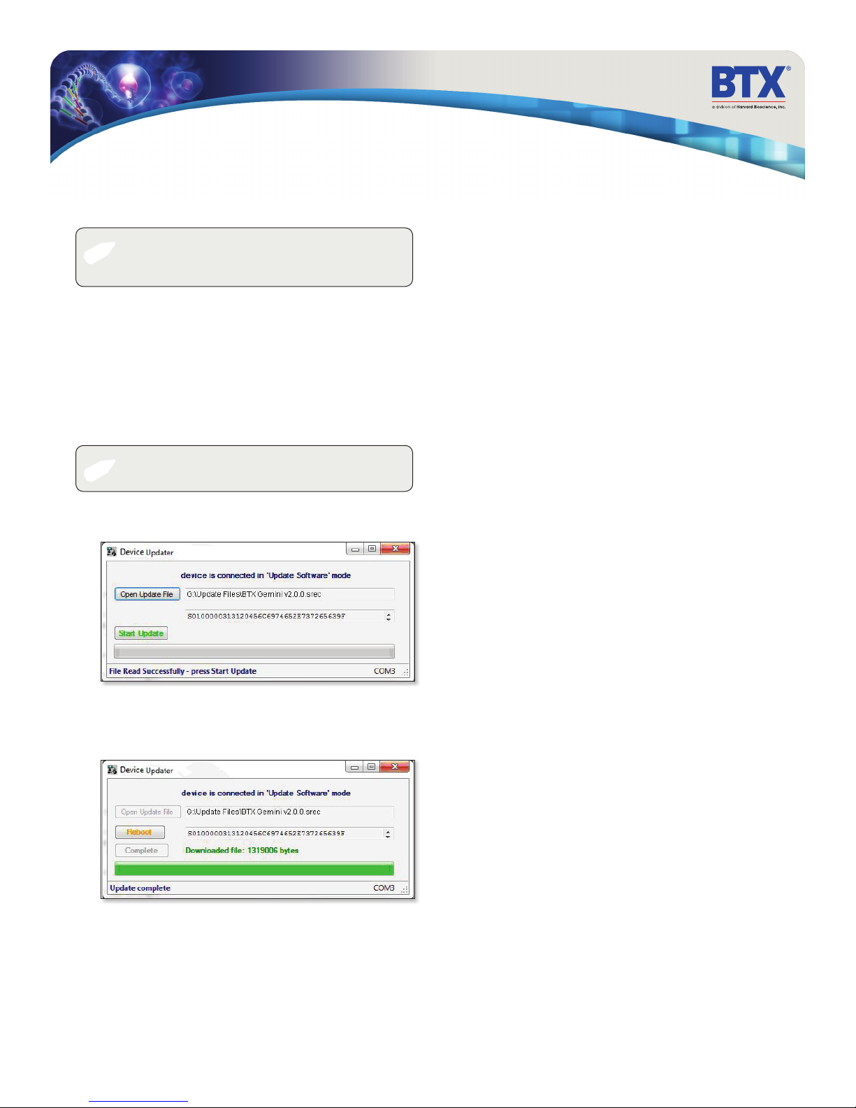
Upgrading Gemini Series Software
Device Updater Program
NOTE: Prior to upgrading, users will need to install USD
✐
1. Upload the latest software versions to your desktop
(format is filename.srec). There are two .srec files that both
need to be updated: ‘BTX Gemini vx.x.x’ and a ‘BTX Gemini
Pwr vx.x.x’.
2. Disconnect all I/O devices and then connect the Gemini X2
generator to PC using a USB cable.
3. On the Set up screen of the Gemini X2
the Upgrade Software button twice to enter Boot Loader
Mode.
✐
4. From the CD provided with the Gemini X2 generator, open
the Device Updater Application.
drivers as well as the bootloader driver le. Reference ‘Virtual
Comport Driver Installation’.
generator, press
NOTE: To exit boot loader mode without upgrading the
software, power cycle the generator.
5. Click Open Update File and browse to the ‘BTX Gemini
vx.x.x.srec’. file that was previously saved to the desktop.
6. Click Start Update.
7. After the update is complete, press Reboot and then power
cycle the Gemini X2 generator from the power switch in the
back of the unit.
8. Repeat steps 5 through 7 with the ‘BTX Gemini Pwr
vx.x.x.srec’.
toll free 800.272.2775 • 508.893.8999 • www.btxonline.com
Gemini Series Electroporator User’s Manual
42
Page 43
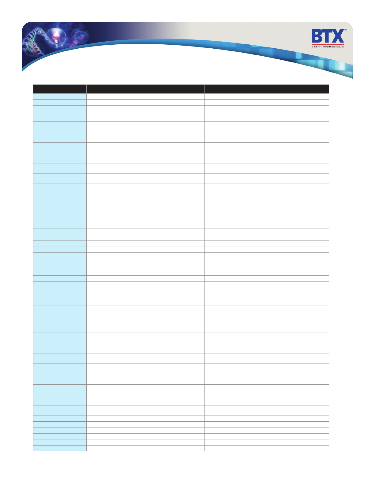
Error Messages & Troubleshooting
Display Error Message Error Description User Troubleshooting
Power Loss Error Power loss during pulsing. Power lost while protocol was running.
PFC Over Temp Pfc module over temperature. Hardware error. Please contact the manufacturer.
Interlock Open Electrode interlock open. Connect electrode connectors to the front of the generator and make sure the
IGBT Switch Fault IGBT switches fault. Hardware error. Please contact the manufacturer.
Charge Voltage Max Error Charging voltage above the expected voltage. Turn off the unit for a few minutes then turn back on. Re-run the protocol if the
Charge Current Max Error Charging current above the expected current. Turn off the unit for a few minutes then turn back on. Re-run the protocol if the
LV Cap Bank Max Low voltage capacitor bank voltage above expected value. Turn off the unit for a few minutes then turn back on. Re-run the protocol if the
LV Cap Bank Min Low voltage capacitor bank voltage below expected value. Turn off the unit for a few minutes then turn back on. Re-run the protocol if the
HV Cap Bank Max High voltage capacitor bank voltage above expected value. Turn off the unit for a few minutes then turn back on. Re-run the protocol if the
HV Cap Bank Min High voltage capacitor bank voltage below expected value. Turn off the unit for a few minutes then turn back on. Re-run the protocol if the
Charge Time Max Charging capacitor bank to selected voltage exceeded max time estimated. Turn off the unit for a few minutes then turn back on. Re-run the protocol if the
Pulse Droop Error Pulse voltage droop exceeded estimated droop. A) Increase the sample resistance. This can be achived by:
Pulse Voltage Overshoot Pulse voltage monitor (p-vmon) pulse overshoot. Hardware error. Please contact the manufacturer
Pulse Voltage Mon too Low Pulse voltage monitor (p-vmon) below min voltage. Hardware error. Please contact the manufacturer
Pulse Voltage Mon too High Pulse voltage monitor (p-vmon) above max voltage. Hardware error. Please contact the manufacturer
Pulse Current Mon too Low Pulse current monitor (p-imon) below min current. Hardware error. Please contact the manufacturer
Pulse Current Mon too High Pulse current monitor (p-imon) above max current. Hardware error. Please contact the manufacturer
Arc_Detected Arc detected during pulsing. Arc could happen due to the one or more of the following conditions:
No_HB_from_GUI Communication error. Hardware error. Please contact the manufacturer
Sample Resistance
Out Of Range
Over Current Pulse Abort Pulse aborted due to pulse over current. The over current protection feature is added to prevent sample arcing.
Idle V I Max Voltage or current in idle state is higher than expected. Turn off the unit for a few minutes then turn back on. Re-run the protocol if the
Charge Cap Bank A Max Charge capacitor bank A voltage is above tolerance. Turn off the unit for a few minutes then turn back on. Re-run the protocol if the
Charge Cap Bank A Min Charge capacitor bank A voltage is below tolerance. Turn off the unit for a few minutes then turn back on. Re-run the protocol if the
Charge Cap Bank B Max Charge capacitor bank B voltage is above tolerance. Turn off the unit for a few minutes then turn back on. Re-run the protocol if the
Charge Cap Bank B Min Charge capacitor bank B voltage is below tolerance. Turn off the unit for a few minutes then turn back on. Re-run the protocol if the
Charge Cap Bank C Max Charge capacitor bank C voltage is above tolerance. Turn off the unit for a few minutes then turn back on. Re-run the protocol if the
Charge Cap Bank C Min Charge capacitor bank C voltage is below tolerance. Turn off the unit for a few minutes then turn back on. Re-run the protocol if the
Dump Time Max The capacitor bank did not fully discharge in the estimated time. Turn off the unit for a few minutes then turn back on. Re-run the protocol if the
Invalid Protocol The generator was requested to run an invalid protocol. Verify that the used protocol is within the allowed specifications of the generator
System Processing (Busy) The control command is invalid or was issued while the generator was busy. Allow more time between events
TC_Error The measured rc time while delivering an exponential decay pulse is invalid. Hardware error. Please contact the manufacturer
Pulse Duration Error The pulse duration did not meet the expected duration. Hardware error. Please contact the manufacturer
Unit Type Sel Error The unit hardware and software do not match the corect type. Hardware error. Please contact the manufacturer
Error: 0X# Multiple errors. Multiple error. Please contact the manufacturer
The measured sample load is out of range. Increase the sample resistance. This can be achived by
cuvett safety dome cover is closed.
issue recurs, contact the manufacturer.
issue recurs, contact the manufacturer.
issue recurs, contact the manufacturer.
issue recurs, contact the manufacturer.
issue recurs, contact the manufacturer.
issue recurs, contact the manufacturer.
issue recurs, contact the manufacturer.
1. Increasing the gap size
2. Reducing the volume
3. Use a less conductive buffer
B) Reduce the pulse duration
1. Sample resistance is very low for the voltage selected
2. Gap size is too small for the voltage selected
3. Pulse duration is too long
1. Increasing the gap size
2. Reducing the volume
3. Replace the buffer with less conductive type of buffer
This could occur when the sample resistance changes during the pulse:
1. Sample resistance is very low for the voltage selected
2. Gap size is too small for the voltage selected
3. Pulse duration is too long
issue recurs, contact the manufacturer
issue recurs, contact the manufacturer
issue recurs, contact the manufacturer
issue recurs, contact the manufacturer
issue recurs, contact the manufacturer
issue recurs, contact the manufacturer
issue recurs, contact the manufacturer
issue recurs, contact the manufacturer
toll free 800.272.2775 • 508.893.8999 • www.btxonline.com
Gemini Series Electroporator User’s Manual
43
Page 44
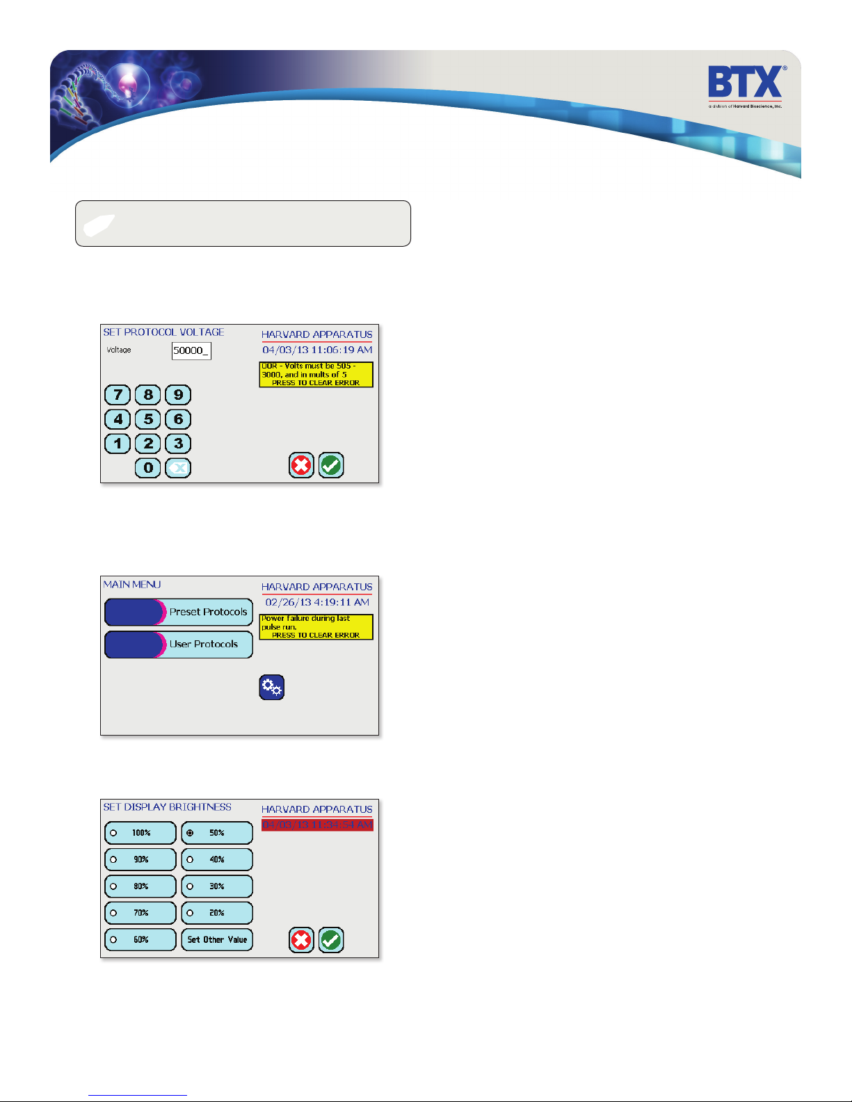
Troubleshooting
NOTE: It is recommended that you save your protocols
✐
Out of Range
A value was entered or encountered in a protocol that was beyond
the generator’s limits.
Power Failure Notification
If power is interrupted during operation, an alarm will sound to
alert the user to the interruption. When power is restored, an
onscreen message is displayed to indicate the interruption.
periodically by uploading them to a PC.
Low Battery Indication
Time/Date area will turn red when battery is low.
toll free 800.272.2775 • 508.893.8999 • www.btxonline.com
Gemini Series Electroporator User’s Manual
44
Page 45

Experiment Troubleshooting
Arcing
Verify electrical component functionality. Verify properties of cell
sample (do cells need to be washed? Is the buffer appropriate for
application?). Verify properties of transfectant molecule (Is the
DNA well purified?) Try reducing the voltage or increase sample
volume until arcing is no longer a problem.
Low (or no) Transfection Efficiency, or
Incorporation
(Verify physical, biological, chemical parameters) Verify delivery
of the pulse and pulse parameters. Is the voltage correct? Chamber
gap? Pulse length or appropriate instrument settings? Number of
pulses? If so, follow Optimization Guidelines outlined.
Low Viability
Verify physical, biological, chemical parameters. Is the voltage,
chamber gap, pulse length (time constant), pulse number and
other instrument settings correct? If so, reduce voltage, pulse
length, or number of pulses and re-optimize protocol to improve
viability as outlined .
Voltage Drop
A drop in output voltage accompanies pulse delivery into highly
conductive samples (for example, PBS). Thus the displayed voltage
may in these situations be less than that expected, given 5% full
scale accuracy and the monitoring accuracy of 5%.
toll free 800.272.2775 • 508.893.8999 • www.btxonline.com
Gemini Series Electroporator User’s Manual
45
Page 46
Ordering Information
Order No. Description UOM
Electroporation Systems
45-2001 BTX Gemini SC Generator only 1 ea
45-2002 BTX Gemini SC Electroporation System.
Includes Gemini SC Generator, Cuvettes - 610, 620,
640 pack of 30 (10 ea), Safety Dome 1, and 660
Cuvette Rack
45-2006 BTX Gemini X2 Generator only 1 ea
45-2007 BTX Gemini X2 Electroporation System.
Includes Gemini X2 Generator, Cuvettes - 610,
620, 640 pack of 30 (10 ea), Safety Dome 2,
and 660 Cuvette Rack
45-2008 BTX Gemini X2 HT Electroporation System. In-
cludes Gemini X2 Generator, Cuvettes - 610, 620,
640 pack of 30 (10 ea), Safety Dome 2, HT 200
Plate Handler, 1 x 2 mm gap HT Plate, 1 x 4 mm
HT Plate and 660 Cuvette Rack
Cuvettes
45-0124 Cuvette Plus, 1 mm gap, 90 µl, pk/50, Gray 50 pk
45-0125 Cuvette Plus, 2 mm gap, 400 µl, pk/50, Blue 50 pk
45-0126 Cuvette Plus, 4 mm gap, 800 µl, pk/50, Yellow 50 pk
45-0140 Bulk Cuvette, 1 mm, 24 pk/100, Gray Case 2400 ea
45-0141 Bulk Cuvette, 2 mm gap, 24 pk/100, Blue Case 2400 ea
45-0142 Bulk Cuvette, 4 mm gap, 24 pk/100, Yellow Case 2400 ea
HT Plates (GeminX2 use only)
45-0462 25 Well Plate, 4 mm gap, 250 µl 1 ea
45-0463 25 Well Plate, 4 mm gap, 250 µl, pk/6 6 pk
45-0466 25 Well Plate, 2 mm gap, 125 µl 1 ea
45-0467 25 Well Plate, 2 mm gap, 125 µl, pk/6 6 pk
45-0450 96 Well Plate, 2 mm gap, 125 µl 1 ea
45-0452 96 Well Plate, 4 mm gap, 250 µl 1 ea
Reagents
45-0802 BTXpress, 5 ml 1 ea
45-0803 BTXpress, 5 ml with 2 mm gap, Cuvettes pk/50 1 ea
45-0804 BTXpress, 5 ml with 4 mm gap, Cuvettes pk/20 1 ea
45-0805 BTXpress, 10 ml 1 ea
45-0806 BTXpress, 10 ml with 2 mm gap, Cuvettes pk/50 1 ea
45-0807 BTXpress, 10 ml with 4 mm gap, Cuvettes pk/40 1 ea
47-0002 Cytoporation Media T 500 ml 1 ea
47-0003 Cytoporation Media T4 500 ml 1 ea
1 ea
1 ea
1 ea
Order No. Description UOM
Accessories
45-0400 HT 100 Plate Handler Manual 1 ea
45-0401 HT 200 Plate Handler Auto 1 ea
45-2020 BTX Safety Dome for SC 1 ea
45-2021 BTX Safety Dome forX2 1 ea
45-2030 BTX Gemini X2 Footswitch 1 ea
45-0208 Cuvette Rack 1 ea
45-0465 HT 25 Well Adapter Plate 1 ea
45-0468 Plate Handler Pins, pk/25 25 ea
45-0469 Plate Handler Pins, pk/100 100 ea
5012-017 Pliers for Plate Handler Removing Pins 1 ea
4500-012 25 Well Plate Seal 2 ea
4500-015 96 Well Plate Seal 2 ea
Cables
45-0216 Connection Cable Cable, 10 ft, Banana to
Micrograbber
45-0204 Tweezertrode Cable / Single Adaptor Cable for
Tissue Slice Electrode Positive
45-0503 Mini Micro Grabber Adapter Cables for Tissue Slice
Chamber / L Shaped Needle Electrodes
45-0087 Micrograbber to Banana Adapter Set 45-0217 1 pr
45-2031 BTX USB Cable, 2 m 1 ea
45-2032 BTX USB Cable, 5 m 1 ea
45-0217 Electrode Cable for Flat Electrode, 10 ft BTB 1 ea
45-0088 Banana Splice F/F Adapter Set, 45-0216/45-0217 1 pr
45-0090 Adapter Set Banana to Pin Tip 1 ea
45-0089 Banana to Square Post Adapter Set for 45-0217 1 pr
1 ea
1 ea
1 ea
toll free 800.272.2775 • 508.893.8999 • www.btxonline.com
Gemini Series Electroporator User’s Manual
46
Page 47
Ordering Information
Order No. Description UOM
45-0101 Caliper Electrode, 1.0 x 1.0 cm Kit 1 Ea
45-0102 Caliper Electrode, 2.0 x 2.0 cm, 1.5 x 1.5 cm Kit 1 Ea
45-0103 Microslide 450, 0.5 mm gap, 20 µl, pk/10 10 Pk
45-0104 Microslide 450-1, 1 mm gap, 40 µl, pk/10 10 Pk
45-0105 Microslide 453, 3.2 mm gap, 650 µl 1 Ea
45-0106 Microslide 453-10, 10 mm gap, 2.0 ml 1 Ea
45-0107 Meander Fusion Chamber, 0.2 mm gap, pk/4 4 Pk
45-0108 Flat Electrode/Divergent Field, 1 mm
(needs 45-0217)
45-0217 Electrode Cable for Flat Electrode, 10 ft BTB 1 Ea
45-0109 Flatpack Chambers, 1.83 mm gap, pk/50 50 Pk
45-0110 Flatpack Chambers, 0.56 mm gap, pk/50 50 Pk
45-0113 Genetrodes Straight, 5 mm, Gold Tip 1 Ea
45-0160 Genetrodes Straight, 5 mm, Gold Tip Kit 1 Ea
45-0114 Genetrodes Straight, 10 mm, Gold Tip 1 Ea
45-0161 Genetrodes Straight, 10 mm, Gold Tip Kit 1 Ea
45-0115 Genetrodes L-Shape, 5 mm, Gold Tip 1 Ea
45-0162 Genetrodes L-Shape, 5 mm, Gold Tip Kit 1 Ea
45-0116 Genetrodes L-Shape, 3 mm, Gold Tip 1 Ea
45-0163 Genetrodes L-Shape, 3 mm, Gold Tip Kit 1 Ea
45-0117 Genetrodes L-Shape, 1 mm, Gold Tip 1 Ea
45-0164 Genetrodes L-Shape, 1 mm, Gold Tip Kit 1 Ea
45-0203 Genetrodes/Genepaddle Holder with Shaft 1 Ea
45-0216 Genetrodes/Genepaddle Cable, 10 ft, BTMG 1 Ea
45-0122 Genepaddles, 3 x 5 mm 1 Ea
45-0169 Genepaddle, 3 x 5 mm Kit 1 Ea
45-0123 Genepaddles, 5 x 7 mm 1 Ea
45-0170 Genepaddle, 5 x 7 mm Kit 1 Ea
45-0167 2-Needle Array, 10 mm Kit 1 Ea
45-0205 2-Needle Array Handle, 10 mm (needs 45-0120) 1 Ea
45-0120 2-Needle Array, 10 mm, pk/6 (needs 45-0205) 1 Ea
45-0168 2-Needle Array, 5 mm Kit 1 Ea
45-0206 2-Needle Array Handle, 5 mm (needs 45-0121) 1 Ea
45-0121 2-Needle Array, 5 mm pk/6 (needs 45-0206) 1 Ea
45-0510 Needle L-Shaped Pt Electrode, 3 mm Kit 1 Ea
45-0509 Needle L-Shaped Pt Electrode, 3 mm
(needs 45-0508)
45-0513 Petri, 7 mm, Tissue Chamber Kit 1 Ea
45-0505 Petri Dish Tissue Chamber, 5 x 5 mm Kit 1 Ea
45-0504 Petri Dish Tissue Chamber, 5 x 5 mm
(needs 45-0216)
45-0506 Petri Dish Tissue Chamber, 15 x 15 mm
(needs 45-0216)
45-0507 Petri Dish Tissue Chamber, 15 x 15 mm Kit 1 Ea
45-0100 Petri Dish Electrode, 2 mm gap, 90 mm Well Dish Kit 1 Ea
45-0130 Petri Pulser for 6 Well Plates, 35 mm Well Kit 1 Ea
45-0490 Tissue Slice Chamber, 7 x 7 mm Kit 1 Ea
1 Ea
1 Ea
1 Ea
1 Ea
Order No. Description UOM
45-0491 Tissue Slice Chamber, 7 x 7 mm Dish
(needs 45-0492, 45-0503, 45-0204)
45-0492 Tissue Slice Wand, (+) 7 mm
(needs 45-0491, 45-0503, 45-0204)
45-0500 Tissue Slice Chamber, 10 x 10 mm Kit 1 Ea
45-0501 Tissue Slice Chamber, 10 x 10 mm Dish
(needs 45-0502, 45-0503, 45-0204)
45-0502 Tissue Slice Wand, (+) 10 mm
(needs 45-0501, 45-0503, 45-0204)
45-0503 Mini Micro Grabber Adapter Cables for Tissue Slice
Chamber / L Shaped Needle Electrodes
45-0530 Adherent Cell Electrode, 3 mm gap
(needs 45-0204)
45-0531 Adherent Cell Electrode, 3 mm Kit 1 Ea
45-0486 PT Tweezertrodes, 1 mm Diameter Kit 1 Ea
45-0487 PT Tweezertrodes, 3 mm Diameter Kit 1 Ea
45-0489 PT Tweezertrodes, 5 mm Diameter Kit 1 Ea
45-0488 PT Tweezertrodes, 7 mm Diameter Kit 1 Ea
45-0165 SS Tweezertrode, 7 mm Diameter Kit 1 Ea
45-0118 SS Tweezertrode, 7 mm Diameter (needs 45-0204) 1 Ea
45-0166 SS Tweezertrode, 10 mm Diameter Kit 1 Ea
45-0119 SS Tweezertrode, 10 mm Diameter
(needs 45-0204)
45-0524 PT Tweezertrode, 1 mm Flat (needs 45-0204) 1 Ea
45-0525 PT Tweezertrode, 1 mm Flat Kit 1 Ea
45-0204 Tweezertrode Cable / Single Adaptor Cable
for Tissue Slice Electrode Positive
Specialty Electrodes (AgilePulse Systems Only)
47-0090 Electrode Adapter Box for Agile Pulse In Vivo 1 Ea
47-0000 Parallel-Needle Array Handle for AP In Vivo 1 Ea
47-0040 4-Needle Array, 4 mm gap, 2 mm Length,
AP In Vivo (ID*)
47-0043 3-Needle Array, 4 mm gap, 3 mm Length,
AP In Vivo (IM)
47-0045 4-Needle Array, 4 mm gap, 5 mm Length,
AP In Vivo (IM*)
47-0050 6-Needle Array, 4 mm gap, 2 mm Length,
AP In Vivo (ID*)
47-0060 6-Needle Array, 6 mm gap, 2 mm Length,
AP In Vivo (ID)
47-0070 6-Needle Array, 6 mm gap, 10 mm Length,
AP In Vivo (IM*)
47-0080 6-Needle Array, 6 mm gap, 12 mm Length,
AP In Vivo (IM)
47-0086 6-Needle Array, 6 mm gap, 16 mm Length,
AP In Vivo (IM)
47-0204N 5 ml Chamber for Agile Pulse Max 1 Ea
47-0090 Electrode Adapter Box for Agile Pulse In Vivo 1 Ea
47-0206 10 ml Chamber for Agile Pulse Max 1 Ea
1 Ea
1 Ea
1 Ea
1 Ea
1 Ea
1 Ea
1 Ea
1 Ea
1 Ea
1 Ea
1 Ea
1 Ea
1 Ea
1 Ea
1 Ea
1 Ea
toll free 800.272.2775 • 508.893.8999 • www.btxonline.com
Gemini Series Electroporator User’s Manual
47
Page 48

Warranty Information
RESEARCH ONLY
BTX
84 October Hill Rd
Holliston, MA 01746, USA
Phone: 1-508-893-8999
Fax: 1-800-429-5732
Web: www.btxonline.com
Warranty
BTX warranties the Gemini X2 & BTX Gemini SC Twin Waveform
Electroporation Systems for a period of two years from the date
of purchase. At its option, BTX will repair or replace the unit if
it is found to be defective as to workmanship or materials. This
warranty does not extend to any instrumentation which has been
(a) subjected to misuse, neglect, accident or abuse, (b) repaired
or altered by anyone other than BTX without BTX express and
prior approval, (c) used in violation of instructions furnished
by BTX. This warranty extends only to the original customer
purchaser. IN NO EVENT SHALL BTX BE LIABLE FOR INCIDENTAL
OR CONSEQUENTIAL DAMAGES. Some states do not allow
exclusion or limitation of incidental or consequential damages so
the above limitation or exclusion may not apply to you. THERE ARE
NO IMPLIED WARRANTIES OF MERCHANTABILITY, OR FITNESS
FOR A PARTICULAR USE, OR OF ANY OTHER NATURE. Some states
do not allow this limitation on an implied warranty, so the above
limitation may not apply to you. Without limiting the generality
of the foregoing, BTX shall not be liable for any claims of any kind
whatsoever, as to the equipment delivered or for non-delivery of
equipment, and whether or not based on negligence. Warranty
is void if the BTX Gemini X2 & BTX Gemini SC instrument is
changed in any way from its original factory design or if repairs
are attempted without written authorization by BTX. Warranty is
void if parts, connections or electrodes not manufactured by BTX
are used with the BTX Gemini X2 & BTX Gemini SC instrument. If
a defect arises within the warranty period, promptly contact BTX,
84 October Hill Road, Building 7, Holliston, Massachusetts, USA
01746-1388 using our toll free number 1-800-272-2775 (US Only)
or 508-893-8999
(E-mail: [email protected]). Goods will
not be accepted for return unless an RMA (Returned Materials
Authorization) number has been issued by our customer service
department. The customer is responsible for shipping charges.
Please allow a reasonable period of time for completion of repairs,
replacement and return. If the unit is replaced, the replacement
unit is covered only for the remainder of the original warranty
period dating from the purchase of the original device. This
warranty gives you specific rights, and you may also have other
rights, which vary from state to state.
will be glad to help at no charge.
Repair service will be billed on the basis of labor and materials.
A complete statement of time spent and materials used will
be supplied. Shipment to BTX should be prepaid. Your bill will
include return shipment freight charges.
Disassembly by the user is prohibited. Service should only be
carried out by experienced BTX technicians.
Repair Facilities and Parts
BTX stocks replacement and repair parts. When ordering, please
describe parts as completely as possible, preferably using our part
numbers. If practical, enclose a sample photo or drawing.
Caution Notice
The BTX Gemini X2 & BTX Gemini SC systems are intended for
laboratory use only and can be used in research and development
applications. These systems have been designed to meet the
standards for electromagnetic compatibility (EMC) intended for
laboratory equipment applications.
The BTX Gemini X2 & BTX Gemini SC systems comply with
the applicable sections of IEC 61010-1:2012 3rd Ed – Safety
requirements for electrical equipment for measurement, control,
and laboratory use. This product should not be used in the
presence of a flammable atmosphere such as an anesthetic mixture
with air, oxygen, or nitrous oxide.
Out of Warranty Service
Proceed exactly as for Warranty Service above. If our service
department can assist you by phone or other correspondence, we
toll free 800.272.2775 • 508.893.8999 • www.btxonline.com
Gemini Series Electroporator User’s Manual
48
 Loading...