

Page 1
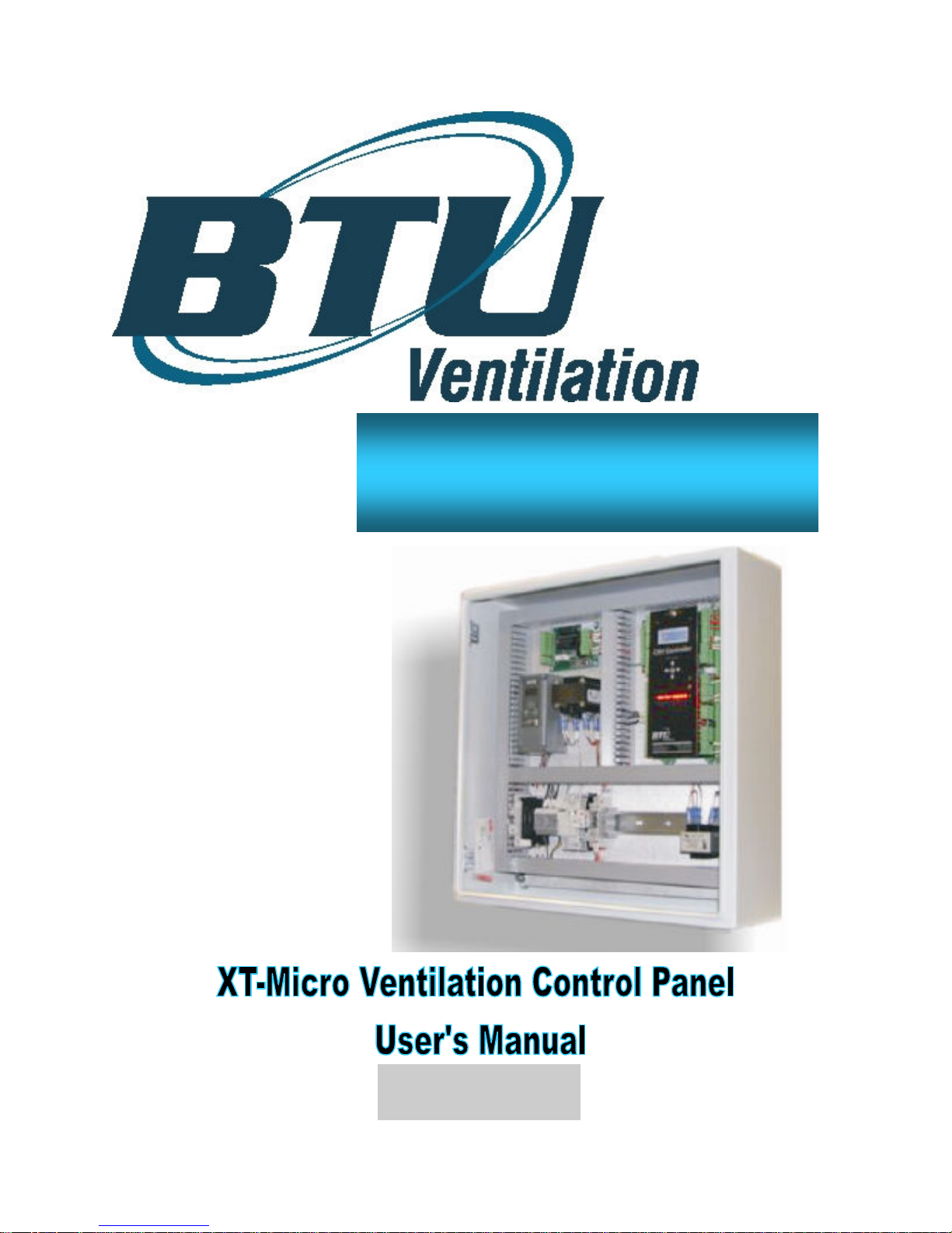
XT-Micro
www.btuvent.com
Manual CRX-001.2
Copyright BTU Ventilation 2010
Page 2

Page 3

XT-Micro Control Panel 3
3
FORWARD
The new CRX Control Panel from BTU Ventilation is built from the ground up for the 21st century farm manager. Simplicity of operation, combined with sophisticated controls make this.
STANDARD FEATURES:
•
Fresh air door control with 1/10 degree control
•
0-20ma Refrigeration control
•
0-20ma Fan VFD speed control
•
On board real time clock calendar
•
8 external relay outputs
•
5 relay outputs
•
Dual Plenum temperature sensors
•
Dual opto isolated RS-485 communication ports
•
Flexible heat mode and Setpoint ramping
•
Back lighted 2x16 local display
•
5 button keyboard
•
Outside and Plenum Humidity sensors
•
CO2 sensor
•
Central distributed time, outside temp and humidity to multiple panels
OPTIONAL FEATURES:
•
Color TPC touch screen interface for up to 10 CRX Bin Controllers.
•
TPC touch screen gateway to internet for remote control and polling of data.
•
Full internet web interface for 10 Bin Controllers using one RGX embedded web server.
•
RGX provides detailed records for up to 10 CRX panels, using web interface. Direct
download into Excel Spreadsheet.
•
RGX provides e-mail and text messaging for up to 10 CRX panels.
•
SDX multiple fresh air door controller
•
VPN web site, look at any number of CRX Bin controllers on one page.
•
VPN records without RGX web interface using TPC Touch screen.
BTU VENTILATION CORPORATION ● OFFICE 888-884-8070 ● FAX 218-346-7485 ● www.btuvent.com
Page 4

XT-Micro Control Panel 4
Page
CRX Sensors
1.0 Input And Output Specifications ………………………………………………. 5
Main Components
2.0 CRX Display & Keyboard …...………………………………………………. 6
2.1 Display Sequence …………………………………………………………….. 6
2.2 Parameter Description ………………….……………………………………. 8
CRX Operation And Alarm modes
3.0 Operational Modes ……………………………………………………………. 17
3.1 Secondary Modes ……………………………………………………………… 19
CRX Operation
4.0 Outside Air Control …………………………………………………………….. 20
Purge Control
5.0 Purge Modes & Theory ….…………………………………………………… 22
5.1 CO2 Flow Chart .……………………………………………………………….. 24
5.2 Sensor Purge Flow Chart …..………….…………………………………….. 25
5.3 Time Purge Flow Chart .……..……………………………………………….. 26
BTU VENTILATION CORPORATION ● OFFICE 888-884-8070 ● FAX 218-346-7485 ● www.btucorp.com
Page 5

XT-Micro Control Panel 5
5
1.0
CRX Sensors:
outputs. In addition, there are two analog outputs that are 0-20mA or 0-10VDC. The fresh air doors
are controlled by two relay outputs.
The CRX panel can accept a number of different input sensors and has 13 one amp
XT Analog Inputs:
•
Plenum 1 F 2250 ohm
•
Plenum 2 F 2250 ohm
•
Outside Air F 2250 ohm
•
Return F 2250 ohm
•
Pile 1 F 2250 ohm
•
Pile 2 F 2250 ohm
•
Pile 3 F 2250 ohm
•
Outside Humid % 4-20mA
•
Plenum Humid % 4-20mA
•
CO2 ppm 4-20mA
XT Digital Inputs:
•
Fan proving Dry contact
•
Cell pump proving Dry contact
•
Refrigeration Fail Dry contact
•
Remote Standby Dry contact
•
Low Temp SPDT contact
•
Start / Stop Dry contact
XT Analog Outputs:
•
Freq Drive 0-20mA / 0-10VDC
•
Refrigeration 0-20mA / 0-10VDC
XT Digital Outputs:
•
Red light
•
Yellow light
•
Fan / Green light
•
Evap cooling pump
•
Humidifier pump 1
•
Heater
•
Aux 1
•
Cavity heater
•
Door open
•
Door close
BTU VENTILATION CORPORATION ● OFFICE 888-884-8070 ● FAX 218-346-7485 ● www.btuvent.com
Page 6
XT-Micro Control Panel 6
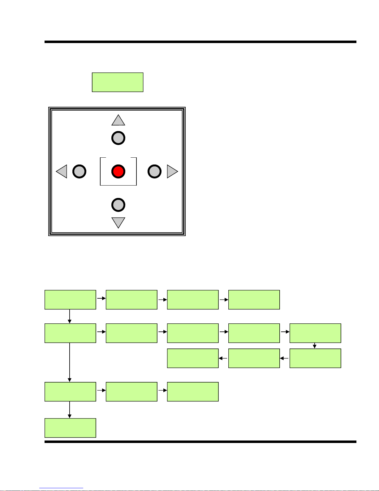
CRX Display & Keyboard
2.0
10/22/09 13:10
Refig Ramp
ENTER
Use up and down arrows to navigate thru the main menu. The left
and right keys are used to access
additional parameters associated
with the main menu.
Programmable parameters are
followed with an *. On any of
these parameters pressing the
ENTER key will activate a cursor
indicating program mode. Press
the up and down arrows to
change the parameter. Use the
left and right keys to move the
cursor on multiple program
screens.
Press the ENTER button when
done to save and escape from the
program mode.
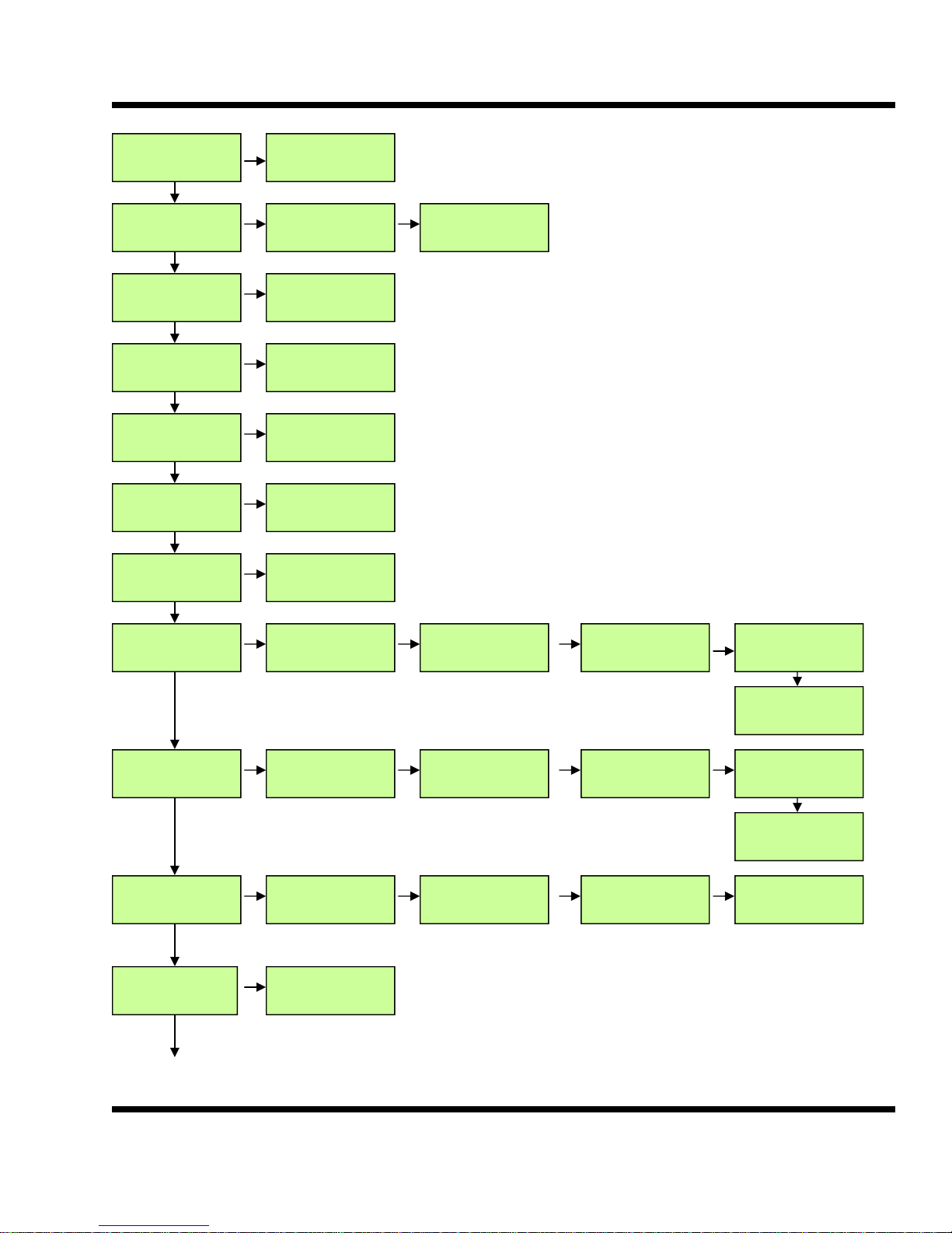
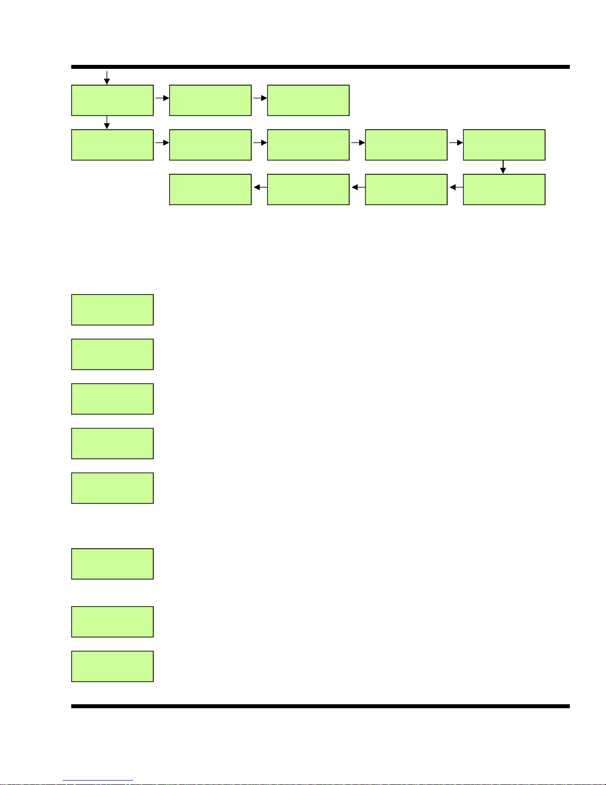
2.1
10/22/09 13:10
Refig Ramp
Temp SP 65.0*
Plenum 65.6
OSA Temp 65.0
Start 65.6
Hum SP 95.0*
Plen Hum 95.0
Daily RT 2.6
Version 00.27
Return 66.0
Pile 1 66.0
OSA Hum 49.0
Wetbulb 10.0
Display Sequence
Total RT 340
Clear? N/Y
Pile 2 66.0
Pile 3 66.0
Ramp Hrs. 0.1*
Ramp Rt 0.5*
OSA Diff -1 *
Force? *
Unit # 1 *
Door Pos 0
Ref Out 100
Temp SP 65.0
Target 65.0*
Plen 1 65.0
Plen 2 65.0
High Dev 5*
Low Dev -5*
BTU VENTILATION CORPORATION ● OFFICE 888-884-8070 ● FAX 218-346-7485 ● www.btuvent.com
Page 7
XT-Micro Control Panel 7
7
CO2 SP 2000*
CO2 1240
Fan Spd 75.0
Cool Sp 65.6*
Heat Diff -2.0* AxH Temp 0.0*
Schedule 1
Cooling *
Schedule 2
None *
Schedule 3
None *
Schedule 4
None *
High CO2 2400*
Timer 15
Recir Sp 60.0*
Min Sp 50.0*
AxH Time 0*
Start 00:00 *
End 24:00 *
Start 00:00 *
End 24:00 *
Start 00:00 *
End 24:00 *
Start 00:00 *
End 24:00 *
Ref Sp 90.0*
Purge Sp 70.0*
Program
PID Values
Program
Timers
Program
Sys Timers
Program
Hum Timers
Cool P 50*
Cool I 10*
Hi Dev 10*
Lo Dev -5*
CAT 10*
MCR 10*
On 10*
Off 10*
Cool D 20*
Cool U 4.0*
Fan Fail 1*
Cell Fail 1*
MRR 30*
Door 180*
Ref P 20*
Ref I 4*
Plen Sen 3*
OSA Sen 3*
Date
11/13/09 *
Ref D 10*
Ref U 10.0*
Filter 6*
OSA H Sen 3*
High CO2 -5*
Plen Diff 1.5*
Time
07:31 *
BTU VENTILATION CORPORATION ● OFFICE 888-884-8070 ● FAX 218-346-7485 ● www.btuvent.com
Page 8
XT-Micro Control Panel 8
2.2
Program
Miscellaneous
AOM Switches Fan
10/22/09 13:10
Refig Ramp
Daily RT 2.6
Version 00.03
Cell Eff 90*
RAS 3*
Auto *
Aux
Off *
Shows date, time and panel mode of operation. No programmable values. The left side
of the bottom line is the main mode and the right side is the secondary mode.
Daily RT (system run time since noon) 2.6 hrs
Version 00.03 software version 0.03
Aux config 3*
Off 20 On 60
Refrig Switch
Manual 25%*
Heat
Auto *
Cavity Switch
Auto *
Humid Switch
Manual *
Parameter Description
Door Switch
Auto *
Clima Switch
Off *
Total RT 340.0
Clear? N/Y
Unit # 1 *
Temp SP 65.0*
Plenum 65.6
Return 66.0
Pile 1 66.0
Pile 2 66.0
Pile 3 66.0
Door Pos 0
Ref Out 100
(Programmable Parameter)
Total Run Time in hours for the year. Clear once a year. Choose Yes to clear time.
(Programmable Parameter)
Unit # is the panel number when used in a network with multiple panels. Each panel
must have a unique number.
(Programmable Parameter)
Temp SP (temperature setpoint) This is the desired plenum temperature setpoint. Press
the ENTER button to change the setpoint.
Plenum is the current plenum temperature. The plenum temperature is the average of
two plenum sensors. The two sensors are located on J7 and J10.
Return is the temperature of the return air and is on terminals 1&2 of J11.
Pile 1 is the temperature sensor located on pins 3&4 of J15.
Pile 2 is the temperature sensor located on pins 3&4 of terminal J18.
Pile 3 is the temperature sensor located on pins 1&2 of terminal J18.
Door Pos is the position of the fresh air doors in percent.
Ref Out is the refrigeration output in percentage.
BTU VENTILATION CORPORATION ● OFFICE 888-884-8070 ● FAX 218-346-7485 ● www.btuvent.com
Page 9
XT-Micro Control Panel 9
9
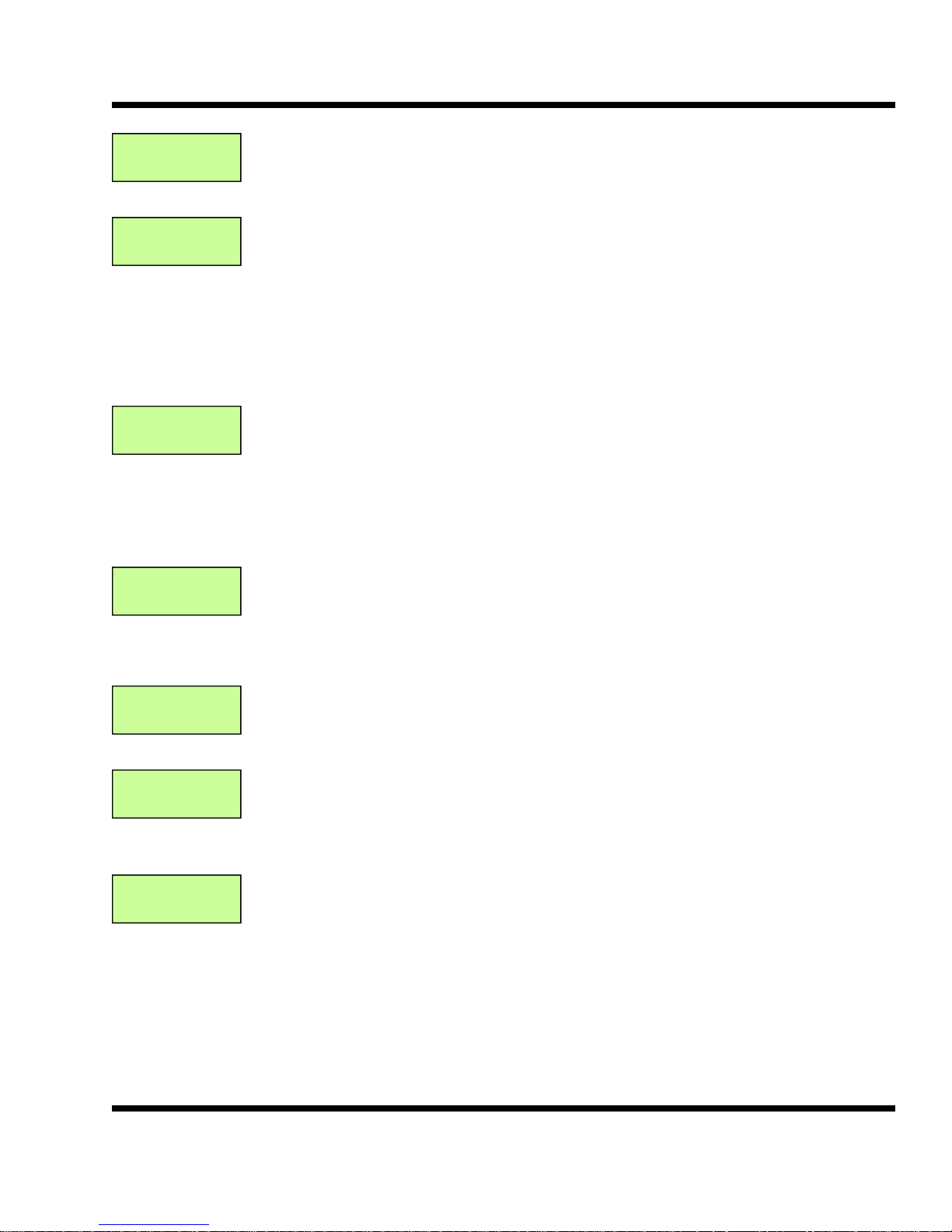
Plen 1 65.0
Plen 2 65.0
High Dev 5*
Low Dev -5*
Temp SP 65.0
Target 65.0*
Ramp Hrs. 24*
Ramp Rt 0.1*
The CRX uses two plenum temperature sensors. Plen 1 is the temperature sensor on
pins 2&3 of J7. Plen 2 is the temperature sensor on pins 2&3 of J10. These two sensors
are averaged and display on the main screen as Plenum.
(Programmable Parameter)
High Dev (High Deviation) is an alarm setting. If the plenum temperature exceeds the
temperature Setpoint plus High Dev a High Deviation alarm will be activated. Press the
ENTER button to change the High Dev setting.
Low Dev (Low Deviation) is an alarm setting. If the plenum temperature is less than the
temperature Setpoint minus the Low Dev a Low Deviation alarm will be activated. To
program the Low Dev setting Press the ENTER button and then press the right button to
position cursor. Make changes using up and down buttons and then press ENTER.
(Programmable Parameter)
This screen is for setting up the Setpoint Ramp function. The Target is the desired temperature setting. The system can ramp down and ramp up. Example: the current Temperature Setpoint is 65.0 and the final desired storage temperature is 45.0. Set the Target to 45.0 and the system will start to gradually ramp the temperature Setpoint down to
45.0. Press the ENTER button to change the Target. The Target can be set above the
Setpoint for warming and ramping up or below the Setpoint for ramping down. To turn
the ramp function off, set the Target the same as the Temp SP.
(Programmable Parameter)
This screen is part of the Setpoint Ramp function. The Ramp Hrs is the number of hours
the system will run before it makes a Setpoint change. Once the system has run the
Ramp Hrs the Setpoint will be incremented or decremented by the Ramp Rate. A typical
setting is .1 degrees.
OSA Temp 65.0
Start 65.6
OSA Hum 49.0
Wetbulb 10.0
OSA Diff -1 *
Force? *
BTU VENTILATION CORPORATION ● OFFICE 888-884-8070 ● FAX 218-346-7485 ● www.btuvent.com
This screen shows when Cooling air will be available. Any time the OSA (outside air
temperature) is less than the Start, Cooling air is available. See the section on outside
air control for the Start calculation.
OSA Hum (outside humidity) Current outside humidity.
The Wetbulb is the wetbulb depression in degrees. At 100 percent saturation, the Wetbulb is the number of degrees of cooling available with the current outside temperature.
(Programmable Parameter)
OSA Diff (outside air differential) This is used to offset the Start temperature. It can be
set plus or minus and is normally defaulted to –1. With no evaporative cooling the Start
temperature would be Setpoint minus the OSA Diff. To program press the ENTER button.
Force? (force cooling or force refrigeration). This is a programmable parameter that allows the operator to force the system into cooling or refrigeration regardless of the outside air temperature. When forced the system will start, open the doors and run for the
MCR (minimum cooling run) timer or MRR (minimum refrigeration run). Press ENTER,
then use the right arrow to get the cursor to Force. Use the up and down arrows to activate the Force Cooling or Force Refrigeration.
Page 10
XT-Micro Control Panel 10
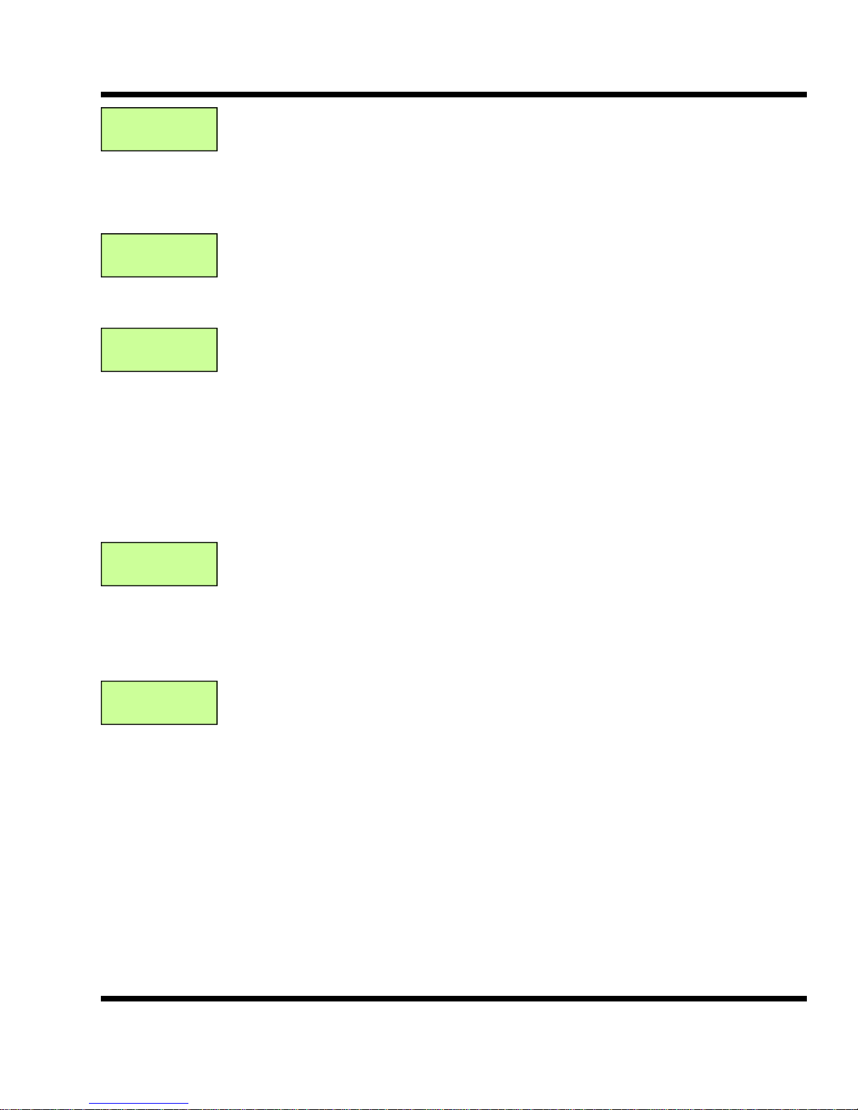
Hum SP 95.0*
Plen Hum 95.0
CO2 SP 2000*
CO2 1240
High CO2 2400*
Timer 15
(Programmable Parameter)
Hum SP (Humidity Setpoint) This is referring the desired Plenum Humidity. Press Enter
to change the Hum SP.
The Plen Hum (plenum humidity) is the actual plenum humidity. Pin 1 of J26 is the plenum humidity sensor input.
(Programmable Parameter)
CO2 SP (CO2 Setpoint) This is the value for the desired CO2 level in the building. The
value is in ppm. To change the SP press the ENTER button. CO2 is the actual value of
the building CO2 level in ppm.
(Programmable Parameter)
High CO2 is an alarm setting. The value is in ppm and can be changed by pressing the
ENTER button. Use the up and down arrows to change the value.
The alarm has an associated timer. The alarm can be disabled by setting the timer to 0.
The timer is in minutes and the CO2 level would need to be higher than the SP for the
amount of the timer to activate the alarm. Once the alarm is activated the system would
shut down. The timer can also be a soft alarm which means that it will alarm, but not
shut the system down. To set the timer soft, the value must be neg. Example: a ten
minute soft alarm would be –10. Press ENTER to change the value and use the up and
down arrows. To go negative, use the down arrow to go past zero.
Fan Spd 75.0
Cool Sp 65.6*
Recir Sp 45.0*
Min Sp 20.0*
(Programmable Parameter)
Fan Spd (Fan speed in %) Fan Spd is the current fan speed in percent.
Cool Sp is the cooling setpoint for the fans when the system in in the Cooling mode. The
Cool Sp is programmable by pressing the ENTER button.
(Programmable Parameter)
Recir Sp (Recirculation Setpoint %) Recir Sp is the Fan speed setpoint when the system
is running in the Recirculation mode. Recir Sp is programmable by pressing the ENTER
button.
Min Sp (Minimum Setpoint %) is the minimum percent the fans can run at if being controlled by the pile differential.
BTU VENTILATION CORPORATION ● OFFICE 888-884-8070 ● FAX 218-346-7485 ● www.btuvent.com
Page 11
XT-Micro Control Panel 11
11
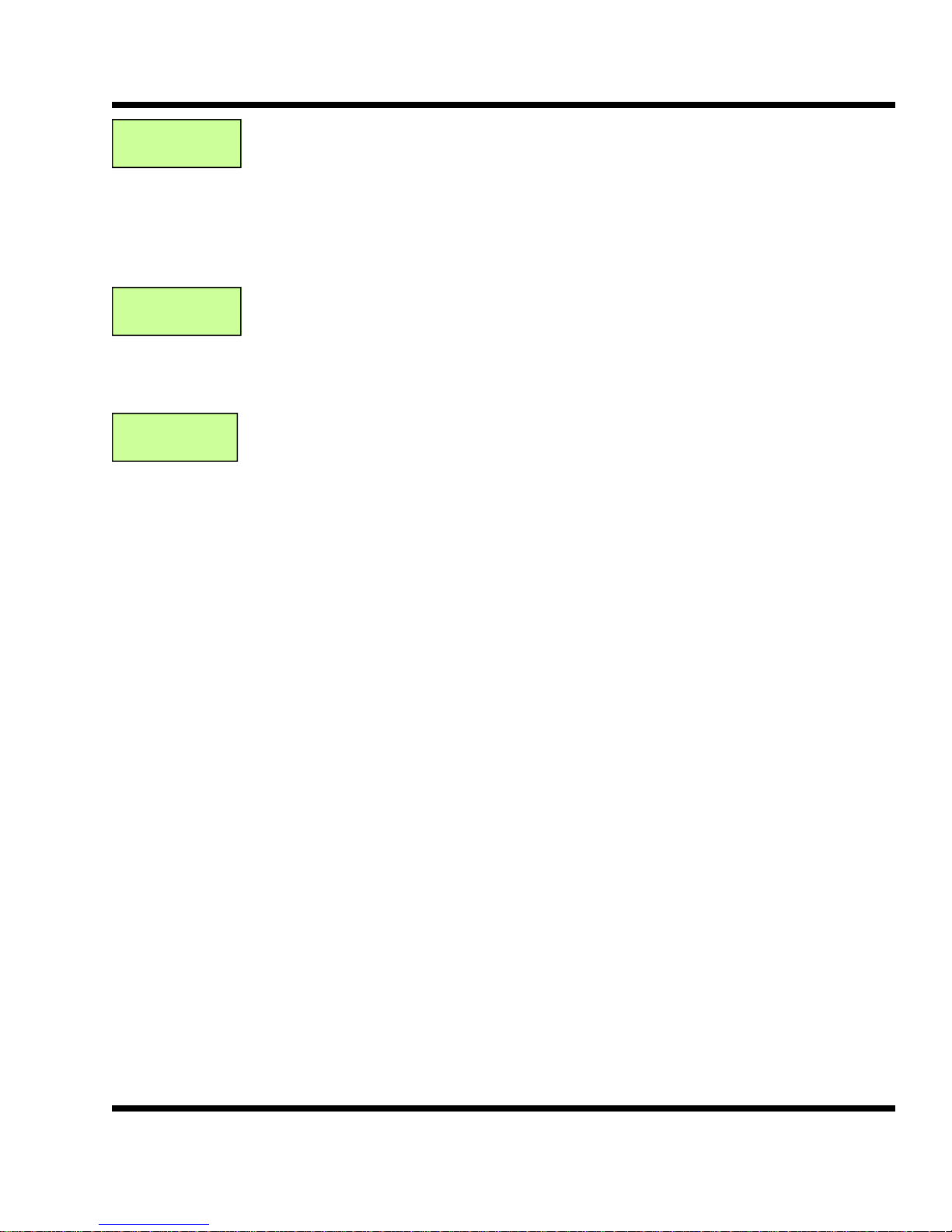
Ref Sp 75.0*
Purge Sp 100*
Heat Diff 0.5*
AxH Temp 50*
AxH Time 10*
(Programmable Parameter)
Ref Sp (Refrigeration Setpoint %) Ref Sp is the speed in percent that the fans will run
when the system is in the Refrigeration mode. Ref Sp is a programmable parameter.
Press ENTER to change.
Purge Sp is the speed in percent that the fans will run when the system is in a Purge.
This is a programmable parameter. Press Enter and then use the right arrow to get the
cursor in the lower line.
(Programmable Parameter)
Heat Diff (Heat Differential) The Heat Diff is used when the plenum temperature drops
below the temperature Setpoint. If the plenum is less than SP - Heat Diff then the return
air heater will turn on. This is a programmable parameter and can be changed by pressing ENTER. This value is a positive number.
(Programmable Parameter)
AxH Temp (auxiliary heat) The AxH Temp is a setpoint of aux heat. The heat could be
located any where in the storage and would be connect to the Aux output. The Aux 1
config byte needs to be set to 5 for this to work. If the outside air temperature drops below the AxH Temp setting the Aux 1 output would turn on.
This has an associated timer AxH Time. The outside air needs to be below the AxH
Temp for the amount of time programmed. The AxH Temp can be programmed by
pressing the ENTER. Press the right arrow to move the cursor to the AxH Time.
BTU VENTILATION CORPORATION ● OFFICE 888-884-8070 ● FAX 218-346-7485 ● www.btuvent.com
Page 12
XT-Micro Control Panel 12
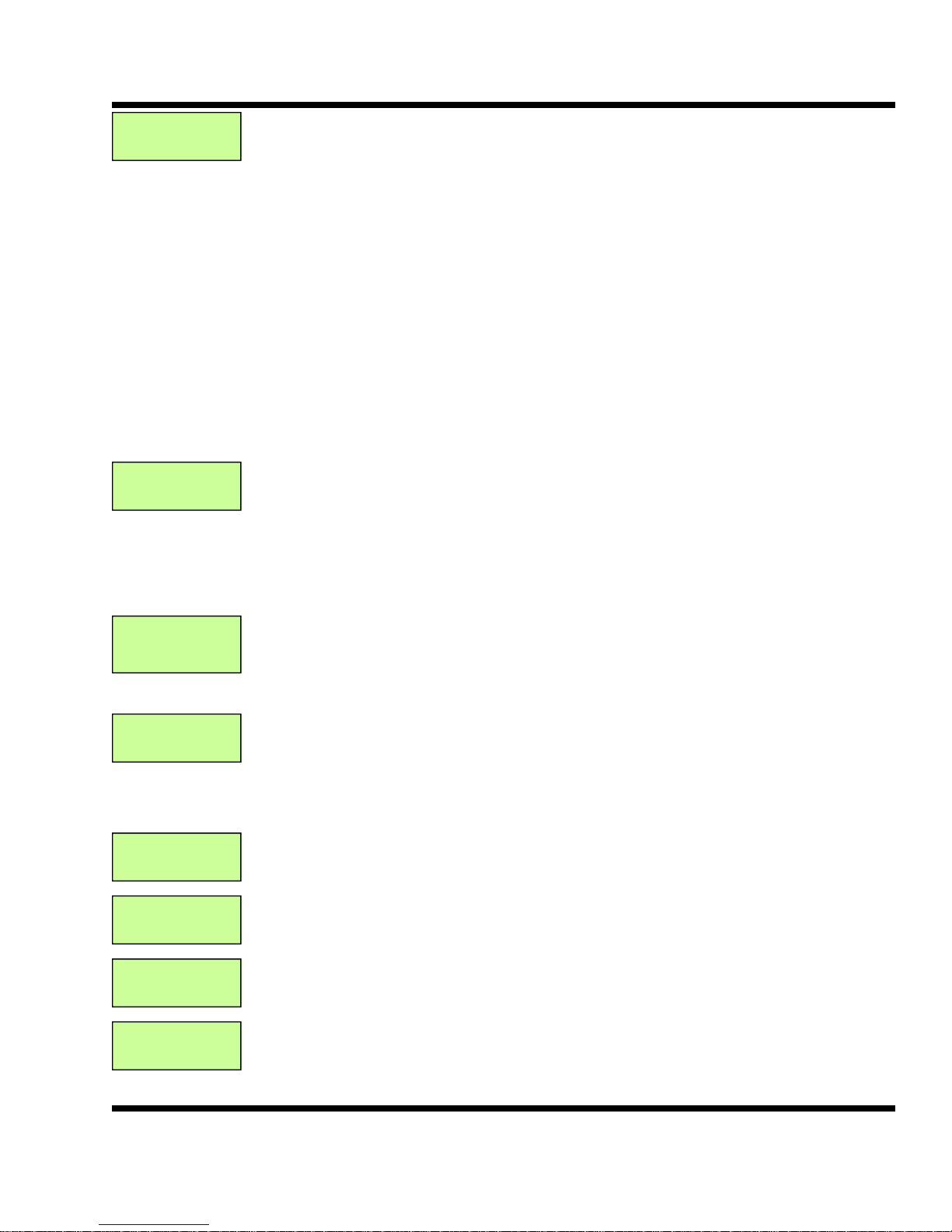
Schedule 1
Cooling *
Start 00:00 *
Stop 24:00 *
(Programmable Parameter)
Schedule 1 The CRX has four different schedulers that can be used to setup the desired
operation of the panel. Each scheduler has six possible modes.
1 None - the scheduler is disabled
2 Cooling - during the scheduled time the system would run in cooling if cooling air
was available.
3 Recirc (Recirculation) - during the scheduled time the system fans would reticulate
the air with the fresh air doors closed.
4 Refrigeration - during the scheduled time the system would run in Cooling if cooling
air was available. If cooling air was not available then the system would run in Refrigeration.
5 Rerfrig Only (Refrigeration Only) - during the scheduled time the system would run
in refrigeration only.
6 Purge - during the scheduled time the system would run a purge cycle.
To change the schedule mode, press the ENTER key and use the up and down keys to
change the mode.
(Programmable Parameter)
Start (Schedule 1) This is the start time for schedule 1 in military 24 hour time. Set for
the desire start time. 00:00 is midnight. Press the ENTER button to program the Start
time.
Stop (Schedule 1) This is the stop time for schedule 1 in military 24 hour time. Set for
the desired stop time. Press ENTER to go into the program mode, use the right arrow to
Schedule 2
Recirc *
Start 23:00 *
Stop 02:00 *
Schedule 3
None *
Start 00:00 *
Stop 24:00 *
Schedule 4
None *
Start 00:00 *
Stop 24:00 *
(Programmable Parameter)
Schedule 2 has priority over Schedule 1. In the above example Schedule 1 is set to run
cooling 24 hours a day. Schedule 2 is set for the Recirc mode. This will have priority
over the Schedule 1 setting. Press the ENTER key to change the Schedule 2 mode.
(Programmable Parameter)
Start (Schedule 1) This example shows the Schedule 2 to Start at 23:00 or 11pm and
Stop at 02:00 or 2am. Thus the system would switch from Cooling to Recirc for this time
period. Press ENTER and use the right key to place the cursor at the desired parameter
to be changed.
(Programmable Parameter)
Schedule 3 has priority over Schedule 1 & 2.
(Programmable Parameter)
Set the desired Start and Stop times for Schedule 3.
(Programmable Parameter)
Schedule 4 has priority over Schedule 1,2 & 3.
(Programmable Parameter)
Set the desired Start and Stop times for Schedule 4.
BTU VENTILATION CORPORATION ● OFFICE 888-884-8070 ● FAX 218-346-7485 ● www.btuvent.com
Page 13
XT-Micro Control Panel 13
13
Program
PID Values
Cool P 50*
Cool I 10*
Cool D 20*
Cool U 4.0*
(Programmable Parameter)
The PID values control the ways that the fresh air doors and refrigeration control temperature. Press the right key to access the PID values for cooling and refrigeration.
(Programmable Parameter)
Cool P (Cooling proportional gain) The default value is 30, increasing this value will
cause the overall system performance to be come faster. P is most effective on sudden
changes.
Cool I (Cooling integral gain) The default value is 8. The integral gain produces an error
based on small errors over time. Increasing this value will cause the small error to be
amplified over time and the system to be more sensitive to static errors.
(Programmable Parameter)
Cool D (Cooling derivative gain) The derivative is produced by a sudden change in the
error. If the temperature is several degrees above setpoint, the PID will ramp quickly.
The error may not change much until the door reaches a given position. At this point the
temperature would drop quickly. The derivative acts like a brake and will offset the error
when large changes are being made. If the temperature over shoots at start up, you
would want to increase the Derivative. The default setting is 20.
Cool U (Cooling update time) This value is in 1/10’s of a second and determines when
the PID loop is updated. The default value is 100. Increasing this value will slow down
the entire loop, decreasing will cause the loop and response to speed up.
Ref P 20*
Ref I 4*
Ref D 10*
Ref U 10.0*
Filter 6*
(Programmable Parameter)
Ref P (Refrigeration proportional gain) The default value is 20, increasing this value will
cause the overall refrigeration system performance to be come faster. P is most effective
on sudden changes.
Ref I (Refrigeration integral gain) The default value is 4. The integral gain produces an
error based on small errors over time. Increasing this value will cause the small error to
be amplified over time and the system to be more sensitive to static errors.
(Programmable Parameter)
Ref D (Refrigeration derivative gain) The derivative is produced by a sudden change in
the error. If the temperature is several degrees above setpoint, the PID will ramp quickly.
The error may not change much until the refrigeration reaches a given position. At this
point the temperature would drop quickly. The derivative acts like a brake and will offset
the error when large changes are being made. If the temperature over shoots at start up,
you would want to increase the Derivative. The default setting is 20.
Ref U (Refrigeration update time) This value is in 1/10’s of a second and determines
when the PID loop is updated. The default value is 100. Increasing this value will slow
down the entire loop, decreasing will cause the loop and response to speed up.
(Programmable Parameter)
The filter is a vale from 1 to 10. This number will weight the analog values for all the temperatures, humidity and CO2 readings. The default value is 6, increasing this value will
cause the readings to be more highly filtered and slower to change.
BTU VENTILATION CORPORATION ● OFFICE 888-884-8070 ● FAX 218-346-7485 ● www.btuvent.com
Page 14
XT-Micro Control Panel 14
Program
Timers
Hi Dev 10*
Lo Dev 5*
Fan Fail 1*
Cell Fail 1*
(Programmable Parameter)
The Program Timers are a group of timers that control all the alarms. A setting of zero
will disable the alarm. A positive setting in the timer will cause the alarm to shut the system down. A negative setting in the alarm will cause the system to alarm, but not shut
the system down. All timers are in minutes. A neg number is still in minutes.
(Programmable Parameter)
Hi Dev (High Deviation Timer) The Hi Dev timer is a count down timer and will alarm if
the alarm conditions remains for the duration of the timer. If the alarm condition clears
part way thru the timer count down, the timer will reset. Press ENTER to change the
timer. The timer is in minutes.
Low Dev (Low Deviation Timer) The Low Dev timer is a count down timer and will alarm
if the alarm conditions remains for the duration of the timer. If the alarm condition clears
part way thru the timer count down, the timer will reset. Press ENTER and then use the
right key to move the cursor to the bottom line to change the timer. The timer is in minutes.
(Programmable Parameter)
Fan Fail (Fan Fail Timer) This is a count down timer that starts when the fan is given a
signal to start. If the fan fails to start before the time counts down a alarm will be triggered. Press ENTER to program the timer. Timer is in minutes.
Cell Fail (Evaporative Cooling pump fail timer) This is a count down timer that starts
when the cell pump is given the signal to start. If the pump fails to start before the time
counts down a alarm will be triggered. Press ENTER and use the right key to move the
cursor to the bottom line. Timer is in minutes. Both timers can be positive, negative or
shut off when set to zero.
Plen Sen 3*
OSA Sen 3*
OSA H Sen 3*
High CO2 -5*
Plen Diff 1.5*
(Programmable Parameter)
Plen Sen (Plenum Sensor Fail Timer) This is a count down timer that will start when
either of the plenum sensors are determined to be out of range. The out of range can be
caused by either a short or open circuit in the wiring. The timer is in minutes and can be
programmed by pressing the ENTER key.
OSA Sen (Outside air Sensor Fail Timer) This is a count down timer that will start when
the outside air sensor is determined to be out of range. The timer is in minutes and can
be programmed by pressing the ENTER key. Both timers can be positive, negative or
shut off when set to zero.
(Programmable Parameter)
OSA H Sen (Outside Humidity Sensor Fail Timer) This is a count down timer that will
start when the outside humidity sensor is determined to be out of range. The timer is in
minutes and can be programmed by pressing the ENTER key.
High CO2 (High CO2 level Timer) This is a count down timer that will be activated when
the CO2 level is greater than the High CO2 setting. The timer is in minutes and can be
programmed by pressing the ENTER key and using the right key to position the cursor.
(Programmable Parameter)
Plen Diff (Plenum Difference Timer) This is a count down timer that will start when the
difference in temperature between the two plenum readings are greater than the Plen
Diff. The timer is in minutes and can be set by pressing the ENTER key.
BTU VENTILATION CORPORATION ● OFFICE 888-884-8070 ● FAX 218-346-7485 ● www.btuvent.com
Page 15
XT-Micro Control Panel 15
15
Program
Sys Timers
CAT 10*
MCR 10*
MRR 30*
Door 180*
Program System Timers: This is a set of timers that are used in the controls primary to
keep the system from short cycling. These timers are only zero or positive numbers.
(Programmable Parameter)
CAT (Cooling Air Available Timer) When the mode changes from Cooling to Standby,
this timer will be active. The setting will force the mode to stay in Standby until this
amount of time elapses. This is to prevent short cycling when OSA cooling is marginal.
The timer is in minutes. Press the ENTER key to change.
MCR (Minimum Cooling Run Timer) This variable is in minutes and will guarantee that
once you go into the Cooling mode, you will stay in this mode for a minimum run time
and not short cycle. Typical settings would be from 15 to 30 minutes. Press the ENTER
key and then use the right key to move the cursor to the lower line to make a change.
(Programmable Parameter)
MRR (Minimum Refrigeration Run) This setting will allow the refrigeration to run for a
minimum time, regardless of cooling air availability. Default setting is 30 minutes. Press
the ENTER key to make changes.
Door (Door Open Time) This time in seconds will determine the door position. This
value is determined by timing the door open cycle and door closed cycle. The two values
should be averaged. The default setting is 180 seconds. This is only used when the ram
potentiometer is not available. Press ENTER key and use the right key to position the
cursor to bottom line to make changes.
Date
11/13/09 *
Time
07:31 *
Program
Hum Timers
On 10*
Off 10*
(Programmable Parameter)
Date (Calendar Date) This allows the date to be set. Press the ENTER key and then
use the up and down arrows to make the change. Use the left and right keys to position
the cursor. Press ENTER when done.
(Programmable Parameter)
Time (Clock Time 24hr) Press the ENTER key and then use the up and down arrows to
make changes. Use the left and right keys to position the cursor. Press ENTER when
done.
Hum Timers (Humidity Timers) This gives access to the programmable timers for turning the Humidifier on and off. Press the right key to go to the timer screen.
(Programmable Parameter)
On (Humidity On Timer) This is the time in seconds that the humidifier will pulse on
when the fans are running. The humidifier will then be off for the programmed amount of
time and then back to the On time. Press ENTER to program. Max value is 250 seconds.
OFF (Humidity Off Timer) This is the time in seconds that the humidifier will pulse off
when the fans are running. The humidifier will be off for this amount of time and then will
pulse on for the On Timer setting. Press ENTER to program and then use the right arrow
to position the cursor. Max value is 250 seconds.
BTU VENTILATION CORPORATION ● OFFICE 888-884-8070 ● FAX 218-346-7485 ● www.btuvent.com
Page 16
XT-Micro Control Panel 16
Program
Miscellaneous
Cell Eff 90*
RAS 3*
AOM Switches
Fan Switch
Auto *
Program Miscellaneous: This allows access to a number of miscellaneous parameters.
Press the right key to access.
(Programmable Parameter)
Cell Eff (Evaporative Cooling Efficiency) The efficiency of different evaporative cooling
cells can vary greatly depending on a number of variables. Cell Eff allows you to set the
efficiency of a given evaporative cooling system. This can be determined by setting the
cell to 100 percent and watching in on a good warm dry day. The setting is from 0 to 100
percent.
RAS (Rise Above Setpoint) This value is what terminates the Cooling air available signal. The RAS is in 1/10 of a degree. A setting of 3 would be .3 degrees above setpoint.
If the Plenum temperature gets above the RAS setting and the outside air is above the
Start temperature then the Cooling mode will be terminated. Press the ENTER key to
change the RAS parameter.
Auto-Off-Manual Switches. These are software switches that can be changed remotely.
For these switches to work the actual hardware switch on the board needs to be in the
Auto position.
Programmable Parameter)
The Fan Switch has three modes. Off, Manual and Auto. In off the Fans will not run regardless of the Stop / Start switch position. In Manual the Fans will run when ever the
Stop / Start switch is in the Start position. In auto the controller will turn the fans on and
off as long as the Stop / Start switch is in the Start position.
Refrig Switch
Auto *
Cavity Switch
Auto *
Door Switch
Auto *
BTU VENTILATION CORPORATION ● OFFICE 888-884-8070 ● FAX 218-346-7485 ● www.btuvent.com
Refrig Switch (Refrigeration Switch) The switch has three positions, Off, Manual and
Auto. Off will prevent the refrigeration from starting. Manual position will all the desired
output percentage to be entered. Used the up and down arrows to change the percentage. When done testing make sure to go back to Auto or Off. The Auto position will allow the controller to turn the refrigeration on and off. Press ENTER to change the position.
Cavity Switch: The switch has three positions, Off, Manual and Auto. This switch controls the output for the cavity heater. Off, Manual and Auto. Off will prevent the cavity
heat from turning on. Manual will turn the cavity heat on all the time. Auto will allow the
program to turn the cavity heat on and off.
Door Switch: The door switch has three positions. This enables the doors to be shut off
or controlled in manual or auto. In manual the doors can be opened or closed using the
up and down keys. Pres the ENTER button to change the mode. If in manual, remember when done testing to switch back to auto.
Page 17
XT-Micro Control Panel 17
17
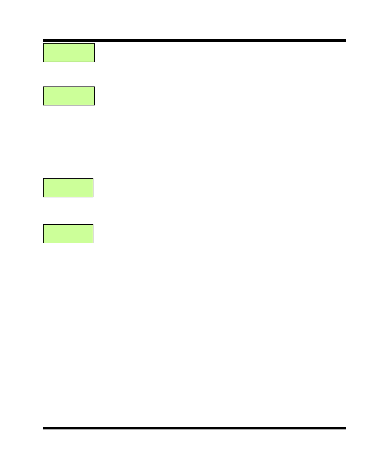
Climacell
Man *
Humidity
Auto *
Heat Switch
Auto *
Climacell is the BTU name for the evaporative cooling cell. This screen shows the status
of the cell. The Cell can be off, auto or manual. In manual the cell will run any time the
fans are running. In off, the cell will not run. In auto the cell can be used to control humidity. To change modes, press the ENTER button and use the up and down arrows to
change the mode.
Humidity refers to the Hum 1 output. This is used to turn on and off the water pump for
the humidifier. The spinner will run all the time. The Hum 1 output has three modes.
Off, Auto and Manual. In Off the humidifier will not run at all. In Manual the humidifier
will run when ever the fans are on. In Auto the Hum 1 output will go on and off to maintain plenum humidity. To change modes, press the ENTER button and use the up and
down arrows to change the mode.
The Heat Switch has three positions, Off, Manual and Auto. In the off position the heat
will not turn on. In the Manual position the return air heat will be on all the time the Stop /
Start switch is in Start. In the Auto position the return air heat will turn on and off when
needed. This is a programmable function and can be changed by pressing the Enter
button.
Aux Switch
Off *
Aux Switch. The Aux switch can be used for any type of addition control. It has three
positions, Off, Manual and Auto. In the off position the Aux output will not turn on. In the
manual position the Aux output will turn on any time the Stop / Start switch is in the Start
position. In Auto the Aux switch will turn on and off when needed. To change press the
Enter button.
BTU VENTILATION CORPORATION ● OFFICE 888-884-8070 ● FAX 218-346-7485 ● www.btuvent.com
Page 18
XT-Micro Control Panel 18
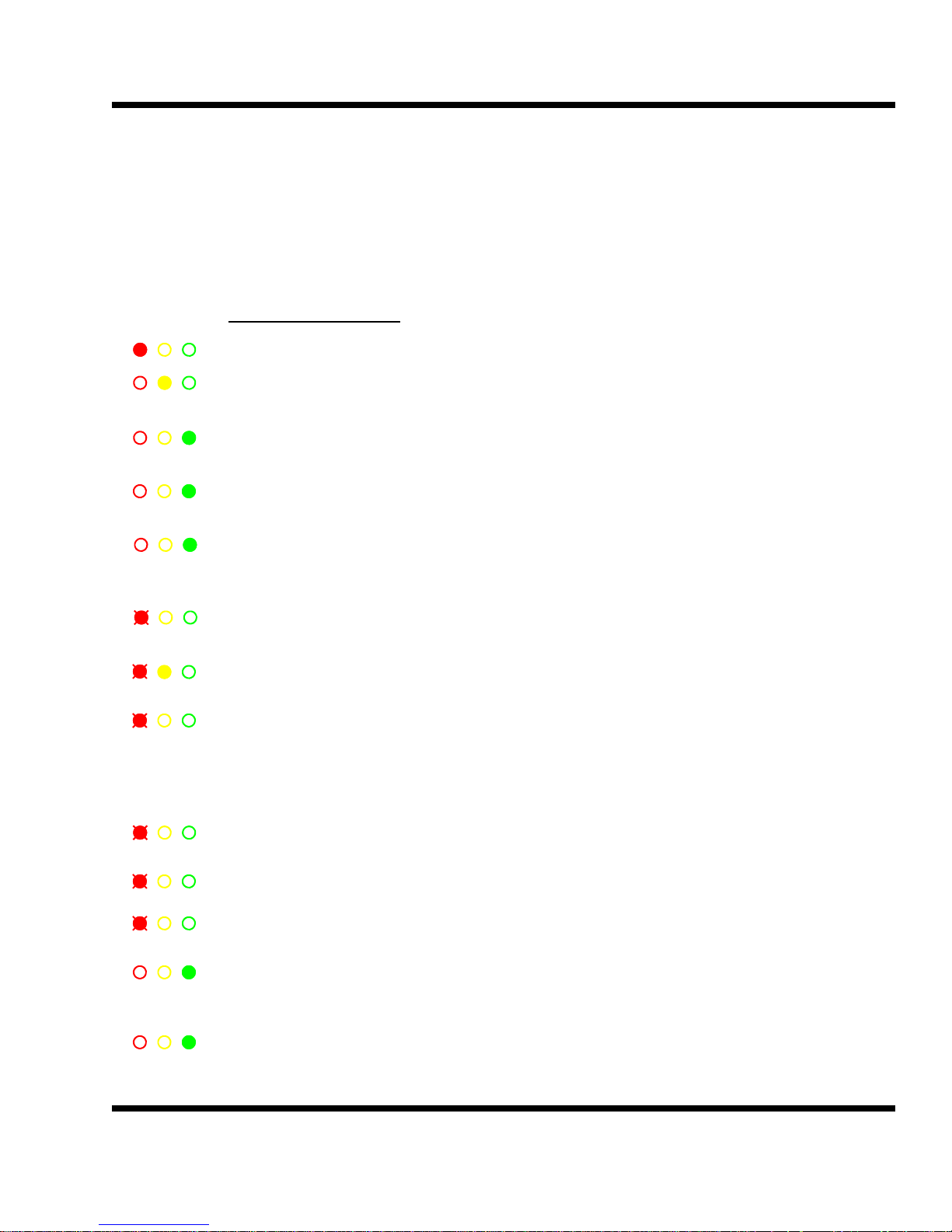
3.0 CRX Modes of Operation
CRX Modes: The XT Panel operates in two modes: the main operation mode and a secondary mode. De-
pending on the setup of the alarms, it is possible to continue running in an alarm mode.
For example, for a cell pump failure, the secondary mode would indicate a cell pump failure, send out the alarm,
indicate an alarm (a blinking red light) but continue to run in Cooling or Refrigeration. Wetbulb calculation would
be shut off.
Main Operation Modes:
Shutdown: Shutdown is activated by the Stop/Start switch set to the Stop position.
Standby: Standby can only be activated with the time clock set to standby or
with no outside cooling available during Cooling mode.
Cooling: Cooling mode can only be activated with outside cooling air available
and time clock set to either Cooling or Refrigeration mode.
Refrig: Refrigeration mode will be activated when cooling air is not available
and the time clock is set for Run or Ref Only.
Recirc Recirc will be activated when the time clock is set to Recirc, there
is no outside cooling air available and the refrigeration switch is set to
Off.
Remote Stop: Remote stop is activated with the Stop button from either the HMI
touch screen or web interface.
Low Temp: The low temp alarm is triggered by the backup low temp safety
thermostat. It can only be reset with the Start/Stop switch.
Parameter Fail: The Parameter fail is triggered by an out-of-range setting on one of the
critical parameters. If setpoint is < 32.0 or > 76.7, the alarm is trig gered. If target is < 32.0 or > 76.7, the alarm is triggered. If pile diff
selection > 8, the alarm is triggered. If Start differential > 50 or < -50,
the alarm is triggered.
Remote Standby: Remote Standby is activated by a contact closure across input IN4.
Typically used for off-peak power, ripple control or refrig defrost.
Alarm Standby: Any alarm condition that was set to shut down the system.
Fan Fail: The fan input IN1 did not get a closed contact within the fan fail timer
period. There is a programmable timer associated with this alarm.
Cooling / Purge: The system is in Cooling and the return air heaters are being used to
force the fresh air doors open. This cycle has been triggered by time
and not the CO2 sensor.
Refrig / Purge: The system is in Refrigeration and the fresh air doors are open to the
max door setting. This cycle has been triggered by time and not the
BTU VENTILATION CORPORATION ● OFFICE 888-884-8070 ● FAX 218-346-7485 ● www.btuvent.com
Page 19

XT-Micro Control Panel 19
19
Timed / Purge: The system is in Timed and the time purge cycle is active. At the
designated time, the fresh air door will open to the max door setting
and purge for the programmed time. This cycle has been triggered by
time and not the CO2 sensor.
Cooling / CO2: The system is in Cooling and the CO2 level is above The CO2 setpoint.
The return air heaters are active to help open the doors and purge the
CO2.
Refrig / CO2: The system is in Refrigeration and the CO2 level is above CO2 setpoint.
The fresh air doors are being used to purge the CO2.
Heat: This mode is used to turn on return air heaters when the system is
running in Cooling, the doors are closed and the plenum temperature
has drop below the Setpoint minus the heat differential.
BTU VENTILATION CORPORATION ● OFFICE 888-884-8070 ● FAX 218-346-7485 ● www.btuvent.com
Page 20
XT-Micro Control Panel 20
3.1
Secondary Modes:
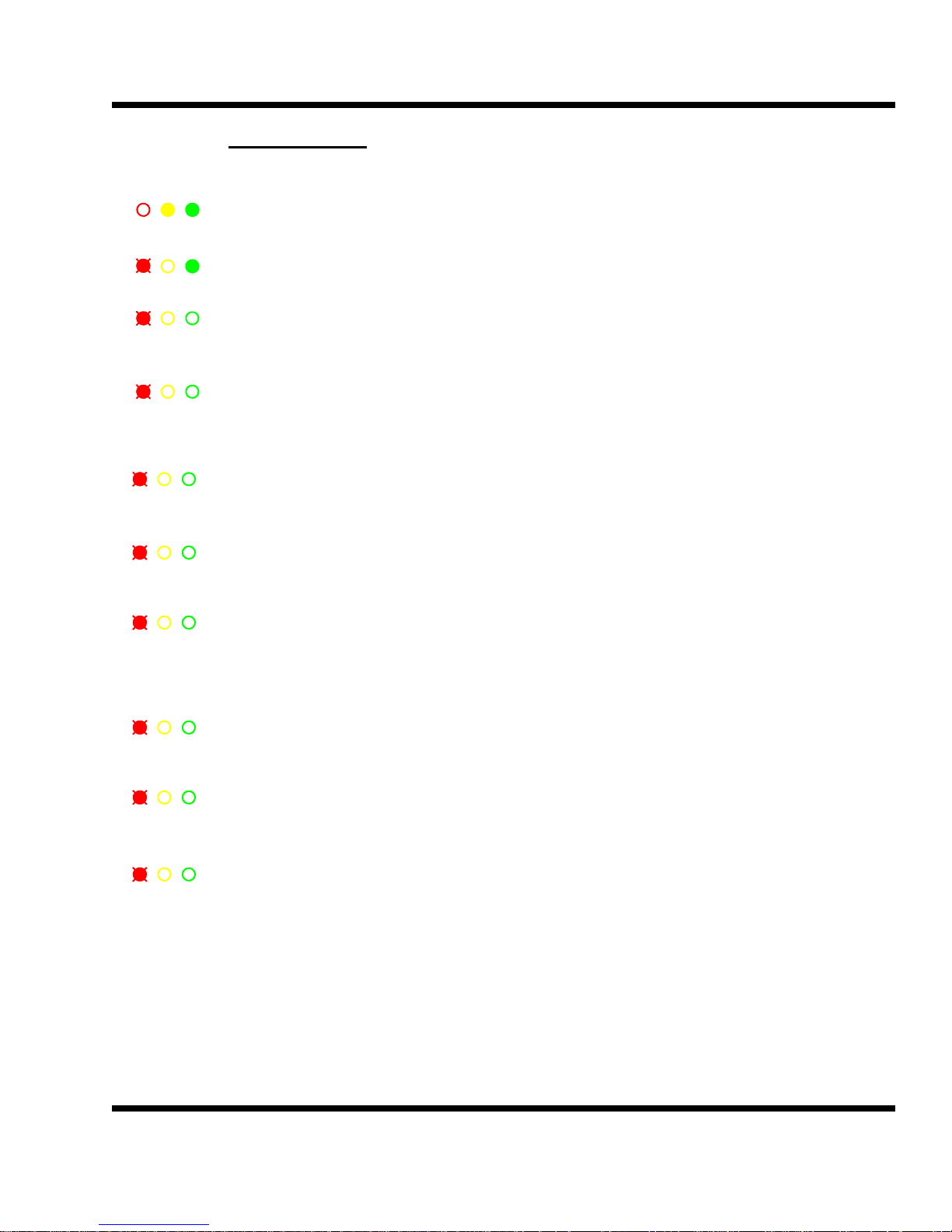
None: There are no secondary modes currently active.
Ramp: The setpoint and target are different values and the system is in the
Ramp mode. The Ramp mode can ramp the setpoint up or down.
Cell Pump Fail: The Cell Pump Fail will trigger when the cell MOA switch is turned to
Auto and the Cell pump input (IN2) is off. There is a programmable
delay timer (CPF_timer) associated with this alarm..
Refrig Fail: The Refrig Fail Alarm will trigger when the refrigeration MOA switch is
turned to Auto, the refrigeration input (IN3) is off and the system is in
Refrigeration mode. The system will continue to run in Cooling mode if
outside cooling is available.
Plen Sensor Fail: The Plenum Sensor Fail alarm is triggered by a programmable differ ence between Plen 1 and Plen 2. There is a programmable timer
Associated with this alarm.
OSA Sensor Fail: The Outside Air Sensor Fail alarm is triggered by an out-of-range out side air sensor. There is a programmable timer associated with this
alarm.
Low Dev: The Low Dev alarm will trigger when the plenum temperature drops
below the low dev setting, the timer has expired and the fans are run ning. There is a programmable timer associated with this alarm.
High Dev: The High Dev alarm will trigger when the plenum temperature rises
above the high dev setting, the timer has expired and the fans are
running. There is a programmable timer associated with this alarm.
OSH Sensor Fail: The Outside Humidity Sensor Fail alarm is triggered by a out-of-range
outside humidity sensor. There is a programmable timer
associated with this alarm.
Low Humidity: The Low Humidity alarm is triggered when the plenum humidity level
drops below the low humidity setting. The system must be in a valid
operating mode. There is a programmable timer associated with this
alarm.
High CO2: The High CO2 alarm is triggered by a CO2 level greater than the high
CO2 setting. The system must be in a valid operating mode. There is a
programmable timer associated with this alarm.
BTU VENTILATION CORPORATION ● OFFICE 888-884-8070 ● FAX 218-346-7485 ● www.btuvent.com
Page 21

XT-Micro Control Panel 21
21
4.0
OUTSIDE AIR CONTROL:
The OUTSIDE AIR CONTROL screen parameter determines when cooling air will be available. The OSA Diff, or
outside air differential, can be plus or minus and provides an offset from the selected reference. The references
is SP (setpoint), With the most basic system with no evaporative cooling, the reference is equal to SP, the start
temperature is equal to SP + OSA Diff. For example, if setpoint is 44.0° and the OSA Diff = -4°, the start temperature would equal 40.0° (44.0 – 4). Any time the outside air temperature falls below 40.0°, cooling air would
be available.
If the storage has evaporative cooling or cell deck installed, this section will explain how the start temperature is
calculated.
Theory: Evaporative cooling can drop the temperature going through the cell by saturating the air. If the
incoming air is very dry (<30 %), drops of up to 20° can be achieved. If the incoming air is very
humid (>70 %), there is very little room to saturate the air and 3 to 5 degrees of cooling may be
all that is available.
Wet_D: Wetbulb depression is the theoretical temperature drop across the cell media. This is a
calculation based on the air being 100 percent saturated when coming out of the cell.
Cell_eff: Cell Efficiency (0-100). The cell material, thickness, amount of water, and design can greatly
affect how well the evaporative cooling will work. The cell efficiency variable will help to
compensate and give an accurate start temperature. For example, most cells produce a
temperature drop of about 80 percent of the actual calculated wetbulb. Thus, if the calculated
wetbulb is 20° and the cell_eff was set to 80%, the adjusted wetbulb would be 16°.
Wet_A: Wetbulb adjusted. This is the theoretical wetbulb multiplied by the cell efficiency variable. This
value should closely match the actual measured drops on the cell medium.
Start_T : Start temperature. Start_T = (Diff_ref + OSA_Diff + Wet_A)
Example: Diff_ref = SP, SP = 45.0°, OSA_Diff = -1, Wet_A = 12
Start_T = (45.0 - 1) + 12 = 56°.
If the outside air was 56° or less, cooling air would be available.
Short cycling of the system can happen when the outside air is very close to the start temperature. Clouds or
other weather conditions can cause the outside air temperature to fluctuate very quickly around the start temperature. The XT panel uses a number of unique ways to prevent this condition from short cycling the system.
MCR Minimum Cooling Run. This variable is in minutes and by default is set to five minutes. Once
the outside air drops below the start temperature, the system will go into Cooling mode. The
MCR time will guarantee that the system will stay in cooling for the duration of the MCR timer.
Thus, if the MCR is set to 5, the system would have to run in Cooling mode for a minimum of
five minutes.
BTU VENTILATION CORPORATION ● OFFICE 888-884-8070 ● FAX 218-346-7485 ● www.btuvent.com
Page 22
XT-Micro Control Panel 22
OUTSIDE AIR CONTROL:
CAT Cooling Air Timer. The CAT timer comes into play when the system terminates Cooling and
goes into Standby mode. The default setting is three minutes. The CAT timer will start timing as
soon as the system switches to Standby. This is a countdown timer, and once it reaches 0, the
system will determine if the outside air temperature is below the start temperature. The system
will go back into the Cooling mode if cooling is available. The CAT timer has an override condi tion - when the outside air is .3° less than the start temperature, the CAT will not be in affect.
RAS Plenum Rise Above Setpoint. The default setting for the RAS is .3°. This is used to determine
when cooling air is no longer available. If the plenum temperature is higher than the RAS setting
and the outside air temp is higher than the start temperature, the system will terminate cooling.
Summary of Cooling Air Logic:
Cooling air available If OSA < Start_T and CAT satisfied or if (OSA - 3) < Start_T.
Cooling air not available If OSA > Start_T
Terminate Cooling Run If OSA > Start_T and Plenum temp > RAS and MCR satisfied.
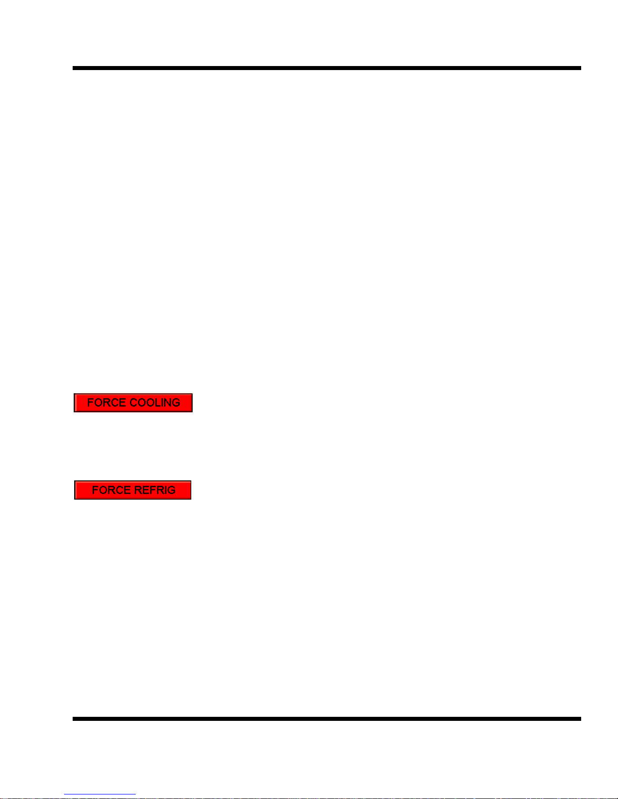
The FORCE COOLING can be used to force the system into a cooling mode. The time clock must be set to allow cooling. Once the system is in cooling, it will run for the minimum cooling time.
The FORCE REFRIG can be used to force the system into a refrigeration mode. The time clock must be set to
allow refrigeration. Once the system is in refrigeration, it will run for the minimum refrigeration time.
BTU VENTILATION CORPORATION ● OFFICE 888-884-8070 ● FAX 218-346-7485 ● www.btuvent.com
Page 23

XT-Micro Control Panel 23
23
5.0
CO2 CONTROL:
Theory
CO2 build up happens primarily during two different conditions. First when the system is in
Cooling and the outside air temperature is very cold. This will cause the fresh air doors to be
closed most of the time. During this period when little fresh air is being introduced in the storage CO2 build can happen fairly rapidly. The best way to purge the CO2 under these conditions is to turn on the return air heaters. The return air heaters will force the return temperature to climb by three degrees. This will cause the fresh air doors to open to maintain plenum
temperature and the CO2 will be purged out the exhaust doors. During this time the fan
speed may be increased to aid in purging the CO2. This second condition for CO2 build up
can occur during long refrigeration runs with the fresh air doors closed. If the refrigeration has
enough capacity the fresh air doors can be slowly opened to 20% until the CO2 is purged out
of the building and then the doors will close.
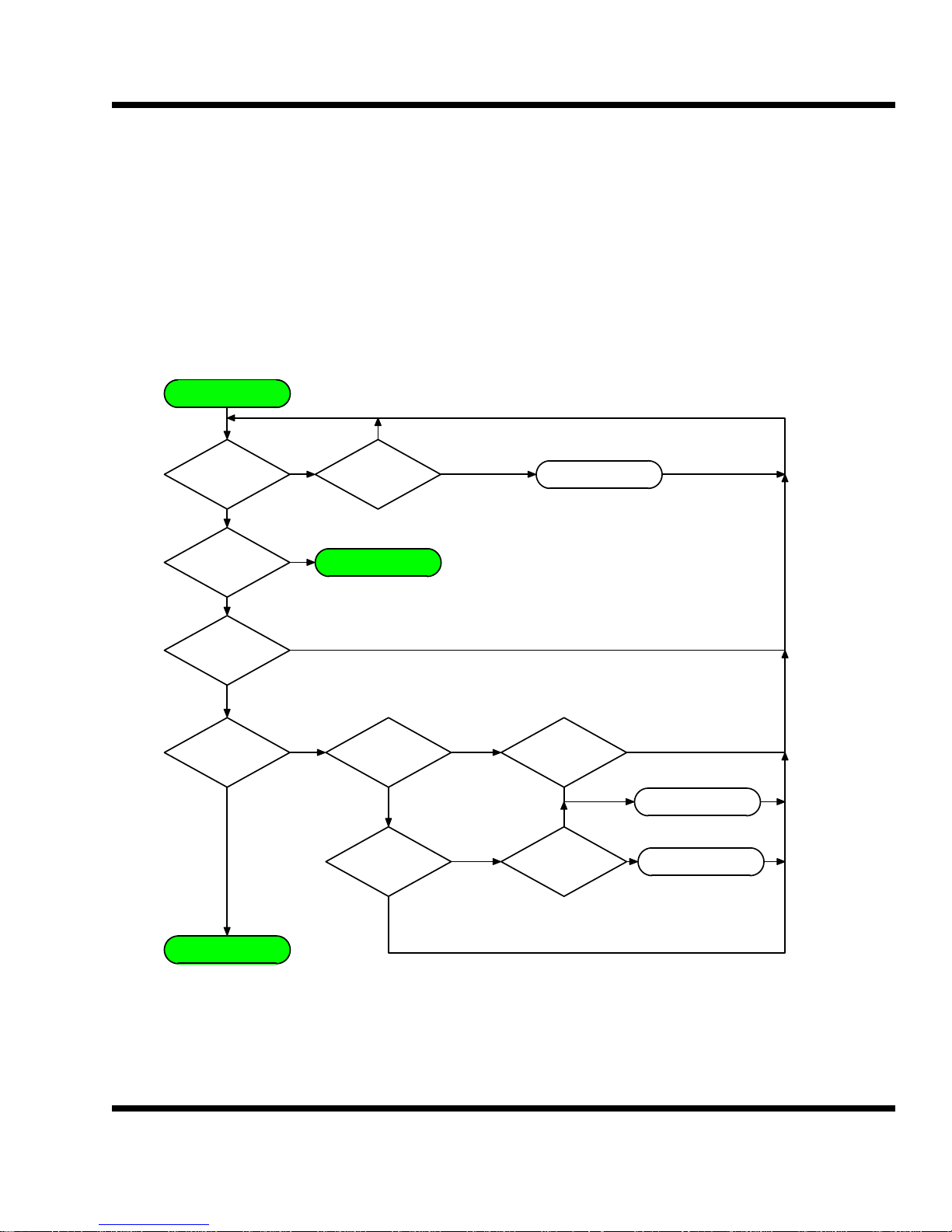
The best scenario is to activate the purge cycle using a CO2 sensor. If a sensor is not available then a purge cycle for cooling or refrigeration can be activated using the programmable
time clock.
The type of CO2 purge is controlled using the Purge_cnfg variable. This variable can be set
to the following applications:
0 = No Purge cycles.
1 = CO2 Time Purge using Time Clock only
2 = CO2 purge during Cooling or Refrigeration mode with CO2 sensor.
3 = Force Purge
Purge_cnfg = 0
No purge: Fresh air doors only open in the Cooling mode to control temperature. Set the
Purge_cnfg equal to zero.
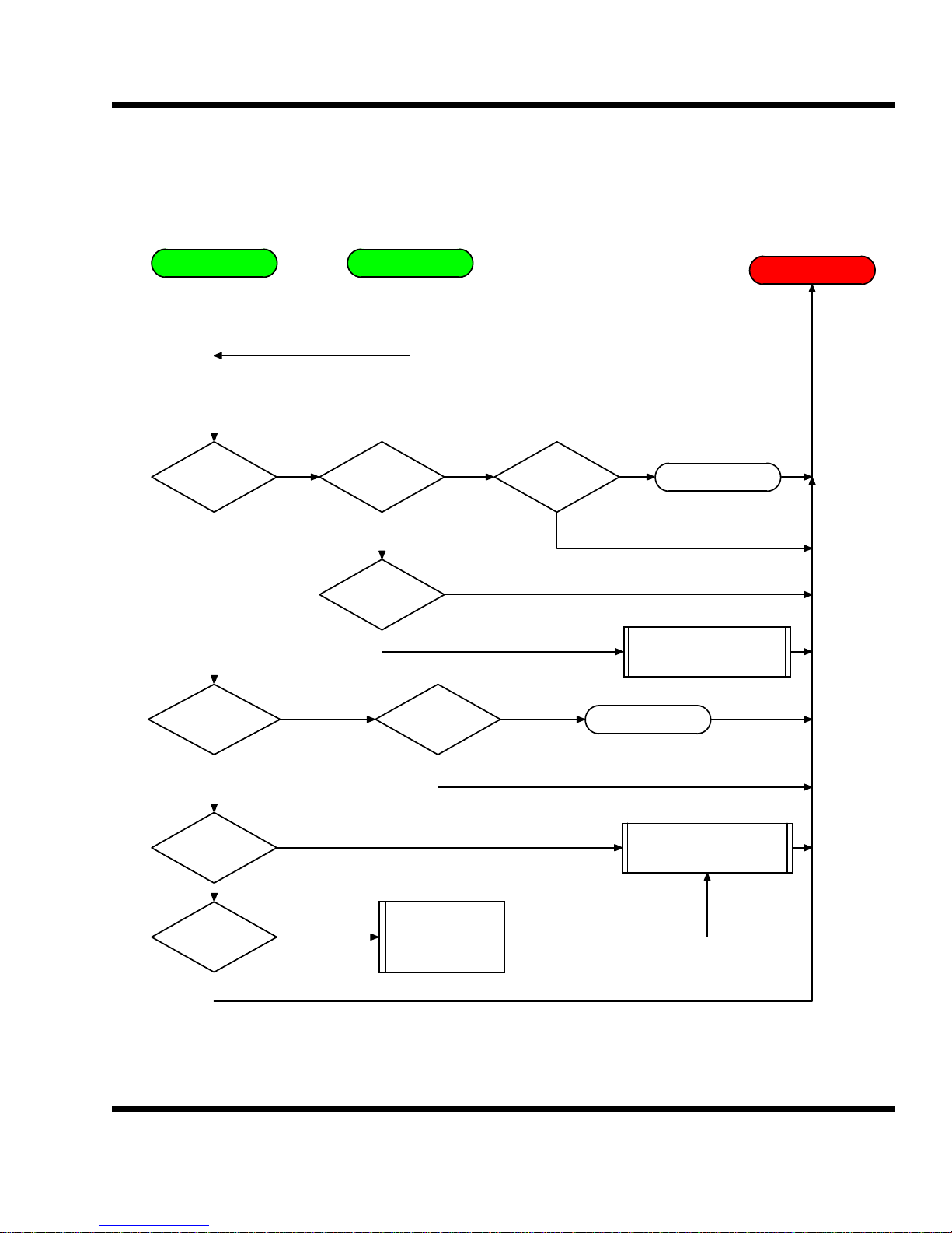
Purge_cnfg = 1
CO2 Time Purge using Time Clock only: This mode will activate a time purge without using a
CO2 sensor. The operator must choose the desire time for the purge on one of the schedule
clocks. The purge schedule should be the set on the last used of the four schedule clocks.
This schedule clock should be set for mode 6 or purge. Choose the desired start and stop
times for the purge. The highest used schedule clock has priority over previous schedule
clocks. Example Schedule clock 1 could be set to run 24 hours in Cooling. Schedule clock 2
could be set for a 20 minute purge from 3am to 3:20am. Schedule clock 2 would have priority
over schedule 1. If the system was in the Cooling Mode and the schedule clock 2 was active
the system would continue to Cooling using the fresh air doors and the return air heater would
BTU VENTILATION CORPORATION ● OFFICE 888-884-8070 ● FAX 218-346-7485 ● www.btuvent.com
Page 24

XT-Micro Control Panel 24
be turned on for the duration of the schedule. If the system was in Refrigeration during the
Schedule 2 time, the fresh air doors would be very slowly opened up to the Max door setting.
Once the Schedule 2 time ends, the doors would be very slowly closed.
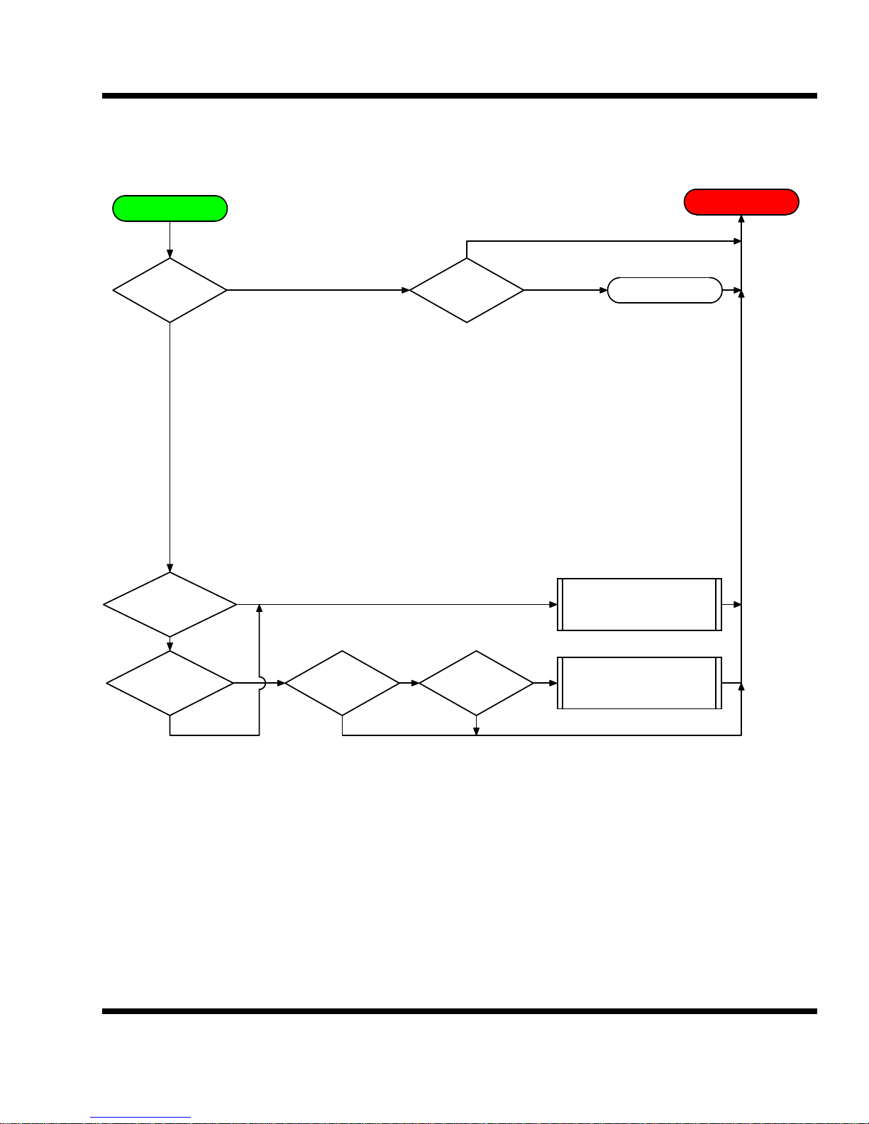
Purge_cnfg = 2
CO2 purge during Cooling or Refrigeration mode with CO2 sensor: This mode will activate a
purge cycle when the CO2 level exceeds the CO2 Setpoint. If the system is running in the
Cooling mode, the return air heaters will be turned on. Once the CO2 level drops 200ppm
below the CO2 Setpoint the heaters will be turned off. When the heaters are on the returned
air is heated should see approximately 3 degrees rise. This will force the fresh air doors to
open. If the system is running in the Refrigeration mode the fresh air doors will gradually
open up to the max door setting. This is typically about 20%. Once the CO2 level drops
200ppm below the CO2 Setpoint the fresh air doors will gradually close.
Purge_cnfg = 3
This is a force purge. The operator must choose the desire time for the purge on one of the
schedule clocks. The purge schedule should be the set on the last used of the four schedule
clocks. This schedule clock should be set for mode 6 or purge. Choose the desired start and
stop times for the purge. The highest used schedule clock has priority over previous schedule clocks. If system is in standby, this purge will start it up in Cooling, open doors to max
setting and run for the duration of the clock.
BTU VENTILATION CORPORATION ● OFFICE 888-884-8070 ● FAX 218-346-7485 ● www.btuvent.com
Page 25
XT-Micro Control Panel 25
l
25
5.1
Operating Parameters:
Door Time sec
Max Door Open 0-100 %
Refrigating level %
REF/CO2 Initial start delay minutes
CO2 Diff
Purge_CFG
0 = No Time Purge or ARL / CO2
1 = Time Purge, no CO2 sensor
2 = CO2 Purge, with CO2 sensor
START
Purge_CFG
= 0
no
Purge_CFG
= 1
yes
yes
Panel Parameters:
CO2 Setpoint (CO2 SP)
CO2 Level 0-10000 ppm (CO2)
Panel Mode
Refrig Output 0-100% (Output)
Plenum Temperature
Plenum Setpoint
CO2 Differential
no
Mode =
Refrig
Goto Time Purge
yes
CO2 Management & Refrigeration Contro
V1.0
CO2 CONTROL
TIME PURGE
Door Closed
no
Purge_CFG
= 2
Mode = Cooling CO2 > CO2 SP
no
Goto Purge Control
no
yes
yes
yes
Heat Switch
= Auto
no
no
yes
CO2 <
CO2 SP - Diff
yes
yes
Door >
Max Door
no
Heat Off
Heat On
no
BTU VENTILATION CORPORATION ● OFFICE 888-884-8070 ● FAX 218-346-7485 ● www.btuvent.com
Page 26
XT-Micro Control Panel 26
CO2 CONTROL
5.3
Purge Control
Mode =
Refrig
yes
CO2 > CO2 SP
no
yes
Mode =
Cooling
Back to Start
yes
Door Closed
no
RUN PID HEAT
MODE & CO2 PURGE
SP = SP + CO2 PLEN RISE
no
CO2 <
CO2SP - DIFF
yes
MODE =
CO2
no
Door = 0 %
no
yes
yesno
RUN PID HEAT
MODE & CO2 PURGE
SP = SP - CO2 PLEN RISE
BTU VENTILATION CORPORATION ● OFFICE 888-884-8070 ● FAX 218-346-7485 ● www.btuvent.com
Page 27
XT-Micro Control Panel 27
TIMED PURGE CONTROL
27
5.4
Time Purge
Time for purge?
yes
Mode =
Cooling
no
no
yes
Force Purge
Mode = Refrig
yes
Door = 0%
no
Heat Switch
yes
Auto
no
no
Mode = Heat
yes
yes
no
SP = SP - CO2 Plen Rise
Heat On
Heat Off
Run CO2 Purge
Back to Start
Mode =
Refrig
no
Purg_CFG
= 3
no
yes
yes
BTU VENTILATION CORPORATION ● OFFICE 888-884-8070 ● FAX 218-346-7485 ● www.btuvent.com
Run CO2 Purge
SP = SP + CO2 Plen Rise
Force Cooling
Limit doors to Max
Page 28
XT-Micro Control Panel 28
TPC-66 Color Touch Screen Wiring and Setup
The TPC-66 is a complete user interface for up to ten XT Micro’s. Besides being a local interface it can also provide remote UDP communications. It also has a VNC web
interface for control via the internet.
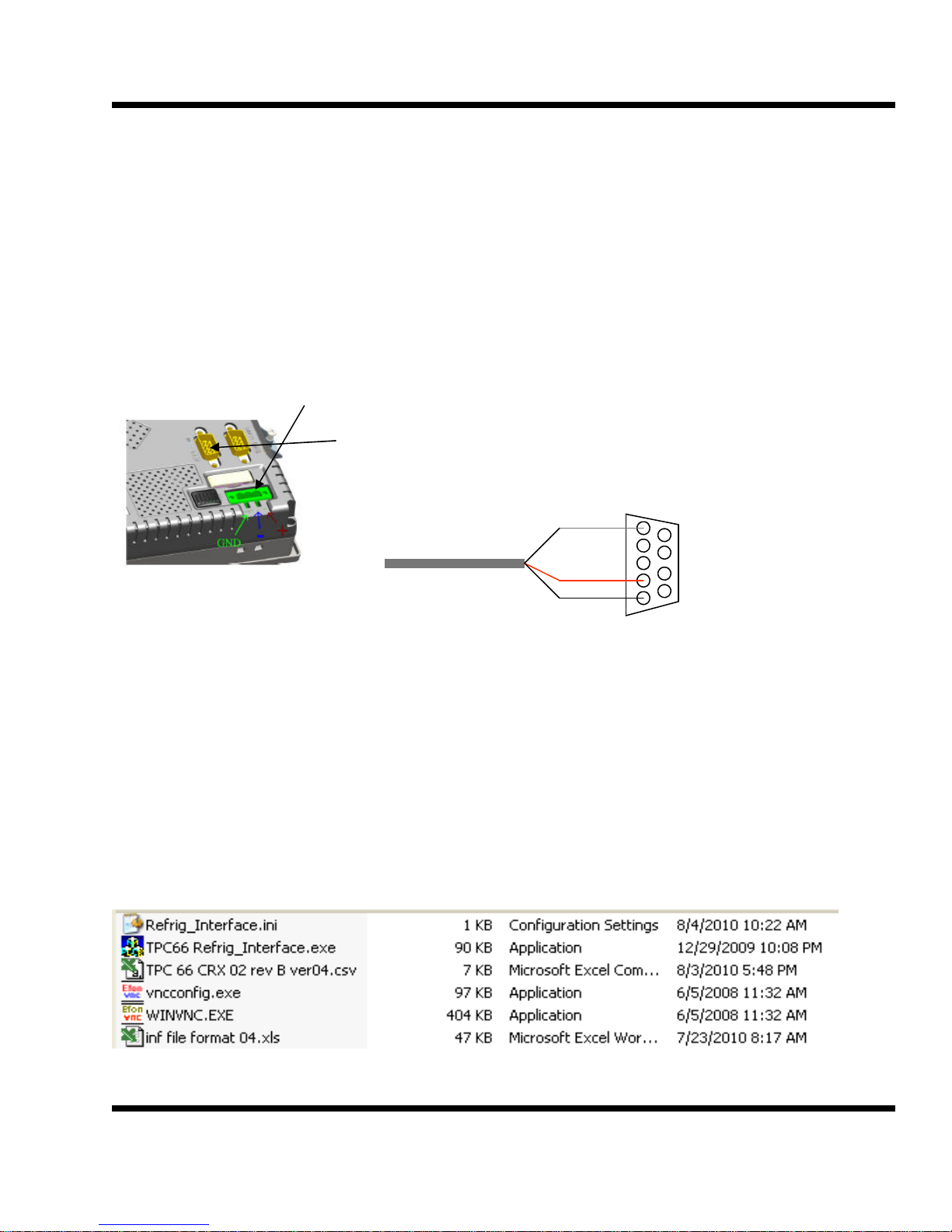
Power and Communications Wiring
The TPC-66 requires 24vdc power and an earth ground. Make sure the polarity is
wired correctly or the unit could be damaged.
The unit uses Com 3 for communications with the XT Micro
cards.
Pin one is Data minus.
Pin two is Data plus.
Pin five is ground.
Initial Setup
The TPC-66 requires a compact flash card for this operation. Make sure the card is
installed. The card slot is on the top of the unit. Open the door and slide the card in.
This card will be referred to as the Storage Card.
The following files are located on the BTU web site in the dealer section under CRX.
The zipped file is named Storage Card.
Com 3 RS-485
gnd
+
-
1
BTU VENTILATION CORPORATION ● OFFICE 888-884-8070 ● FAX 218-346-7485 ● www.btuvent.com
Page 29
XT-Micro Control Panel 29
29
Refrig_Interface.ini file: this file is used to store the configuration settings, such as
baud rate.
TPC66 Refrig_Interface.exe: this file is the actual program file that runs in the TPC.
TPC 66 CRX 02 rev B ver 04: this is a csv file and it is used to setup the TPC program
for different devices. The name of this file will change depending on the project and
the type of equipment. Once the program is up and running, you can choose which of
the csv files to use.
Vncconfig.exe: this is a program that is used to configure the VNC for remote monitoring and control of the TPC.
WINVNC.EXE: this is the actual program for the VNC. It runs in the back ground and
is waiting for a remote connection.
Inf file format 04.xls: this program is not needed and is only used as a guide in setting
up the csv file for the TPC.
STEP 1: (copy files)
Copy the above files onto a USB thumb drive. Power up the TPC-66, with the compact
flash card installed. Plug the USB thumb drive into the TPC-66 USB port.
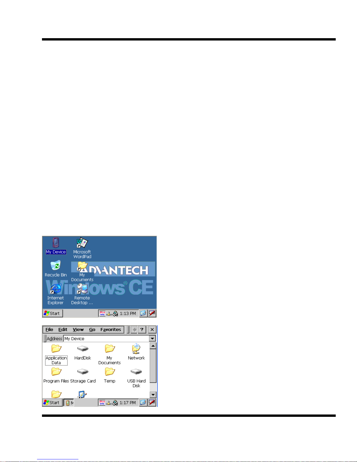
When the TPC-66 boots up for the first time, you
should get this initial screen.
Double tap the My Device icon.
My Device should show the Compact Flash as
the Storage Card and the USB thumb drive as
the USB Hard Disk.
The object is to copy the files from the USB Hard
Disk to the Storage Card.
Double Tap on the USB Hard Disk
BTU VENTILATION CORPORATION ● OFFICE 888-884-8070 ● FAX 218-346-7485 ● www.btuvent.com
Page 30
XT-Micro Control Panel 30
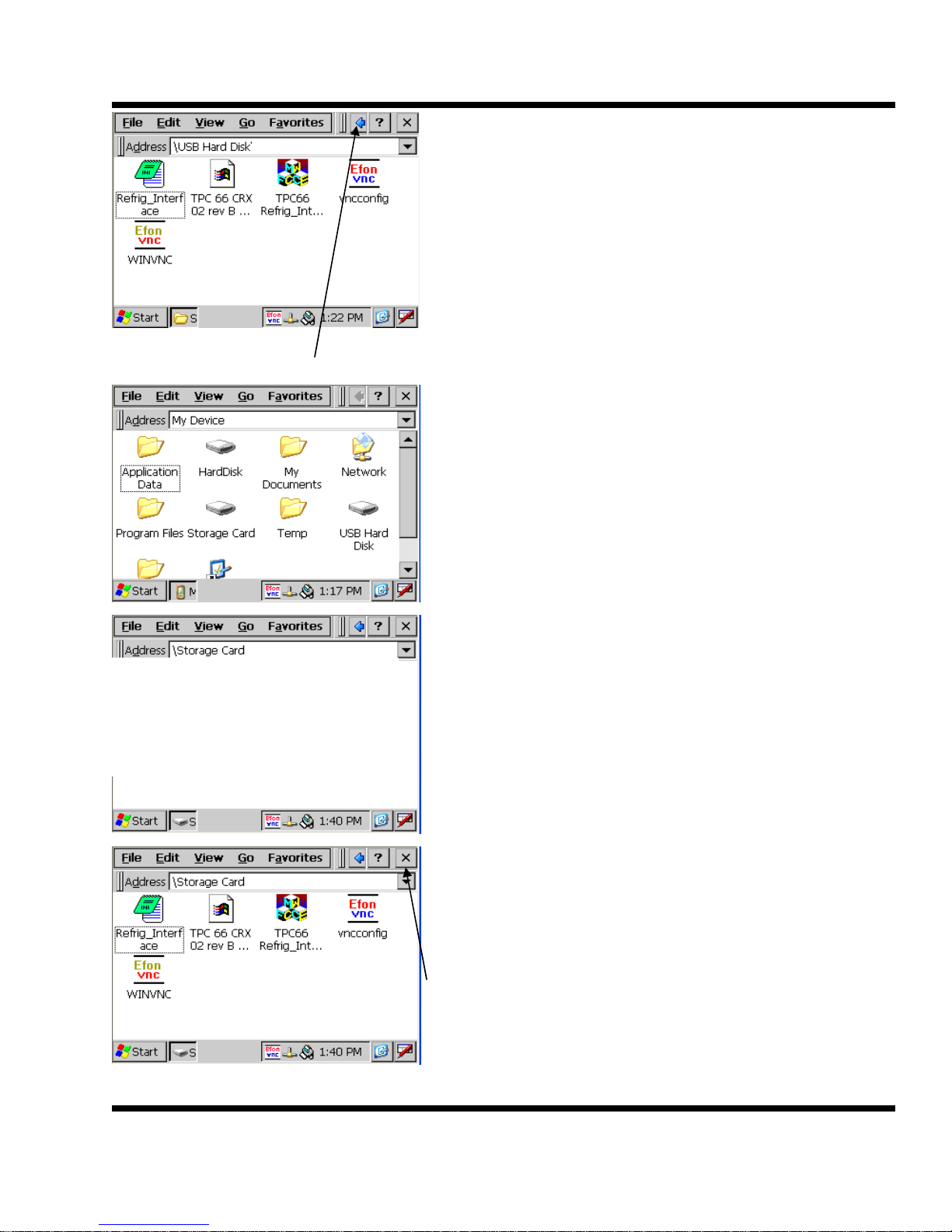
The TPC should now show these files on the
USB Hard Disk. The TPC 66 CRX 02 rev B.csv
file could be named anything. This file is be using for example only.
Tap on Edit and then Select all. All the programs
should now be highlighted.
Next tap on Edit and then on Copy.
Now tap on the back arrow. This will take you back to the My Device screen.
Double tap on the Storage Card.
Tap on Edit and then on Paste
The Storage Card should now have the following
files.
In the future, use this same procedure to update
program and configuration files.
Tap on the X to go back to main screen
BTU VENTILATION CORPORATION ● OFFICE 888-884-8070 ● FAX 218-346-7485 ● www.btuvent.com
Page 31
XT-Micro Control Panel 31
31
STEP 2: (start up menu)
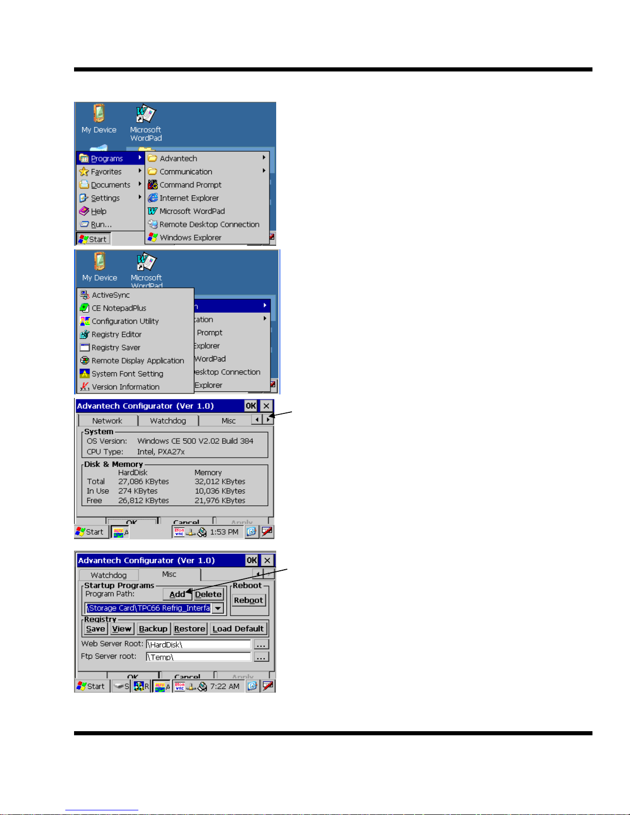
Tap the Start button and then the Programs Button.
Tap the Advantech on the far right at the arrow.
Tap on Configuration Utility
Tap on the right arrow until the Misc tab shows
up. Tap on the Misc tab.
Tap on the Add button.
BTU VENTILATION CORPORATION ● OFFICE 888-884-8070 ● FAX 218-346-7485 ● www.btuvent.com
Page 32
XT-Micro Control Panel 32
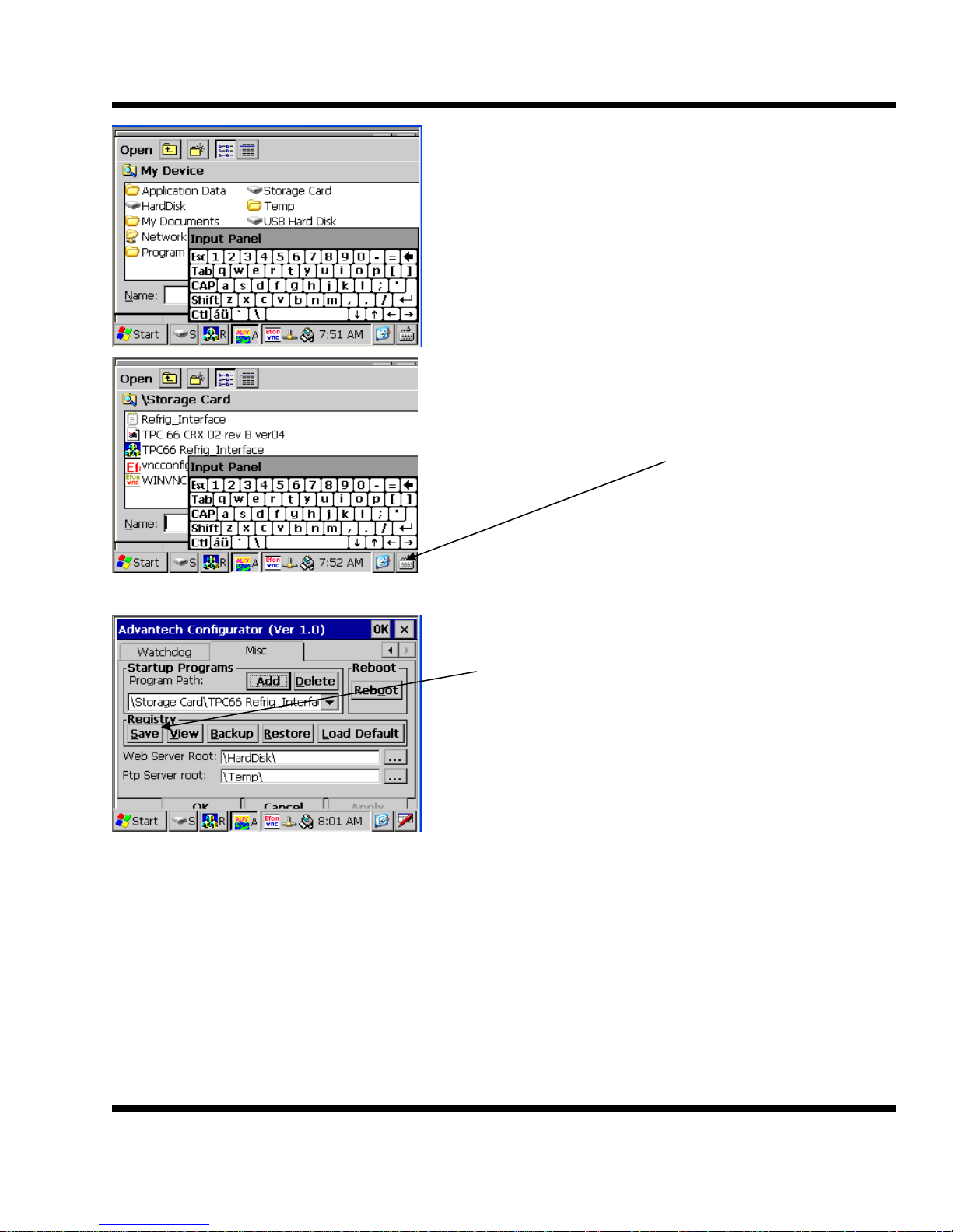
Double tap the storage Card
Tap on the keyboard icon and then on hide input
panel to remove the keyboard.
Double tap on the TPC66 Refrig Interface file.
Tap on the Registry Save button to save the start
up menu.
Tap on OK to exit configurator.
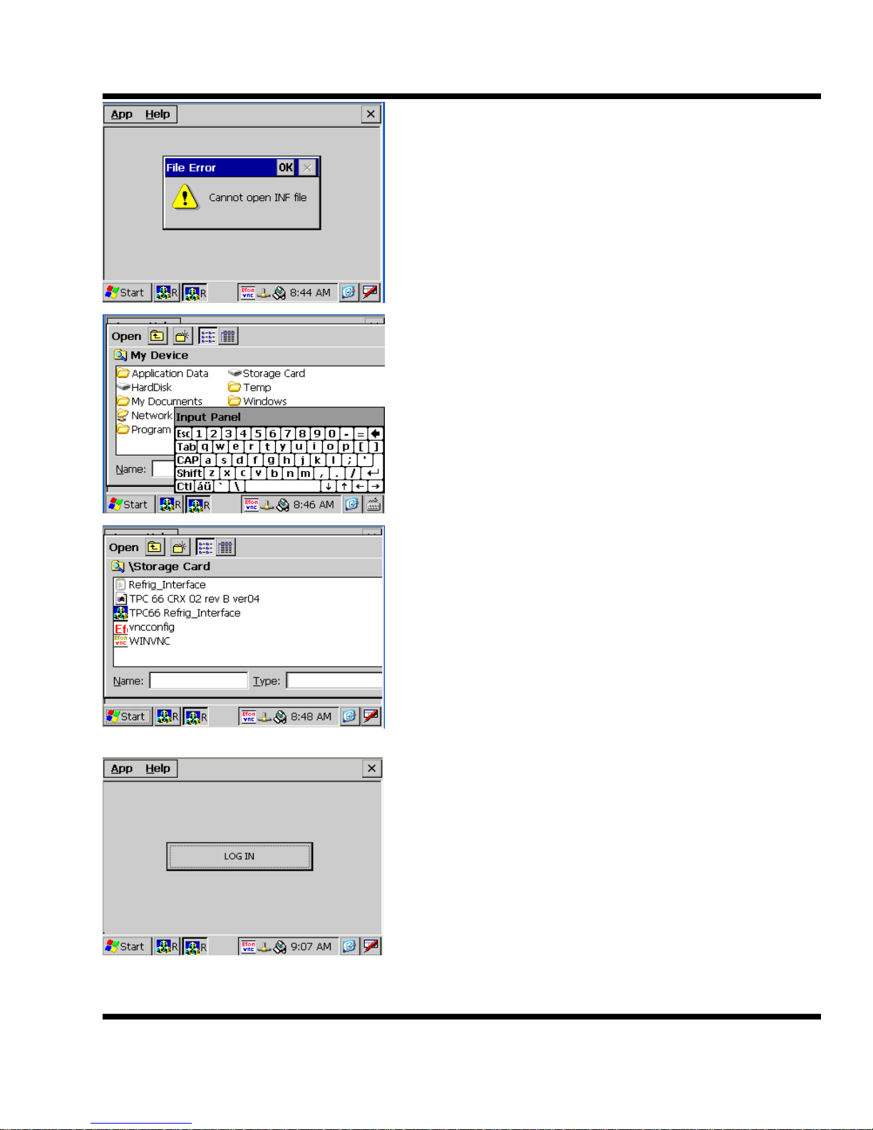
Power the TPC down and back up. It should now start up the control program and
show an error because no INF file has been selected.
BTU VENTILATION CORPORATION ● OFFICE 888-884-8070 ● FAX 218-346-7485 ● www.btuvent.com
Page 33
XT-Micro Control Panel 33
33
Tap OK, then tap App, Set INF
Hide the Input Panel and double tap on the
Storage Card.
Double tap on the correct inf file. The inf file is a
csv file that tells the TPC which units to poll and
how to decipher the data. In this example the file
is the TPC 66 CRX 02 rev B ver 04. This file
could have any name assigned to it. The name
should reflect the equipment it is polling.
Tap on the LOG IN button
Enter the appropriate log in. There can be three
different passwords. The passwords are all set in
the inf file.
The first two password allow view only. The third
password allows configuration. The default password is 3333
BTU VENTILATION CORPORATION ● OFFICE 888-884-8070 ● FAX 218-346-7485 ● www.btuvent.com
Page 34
XT-Micro Control Panel 34
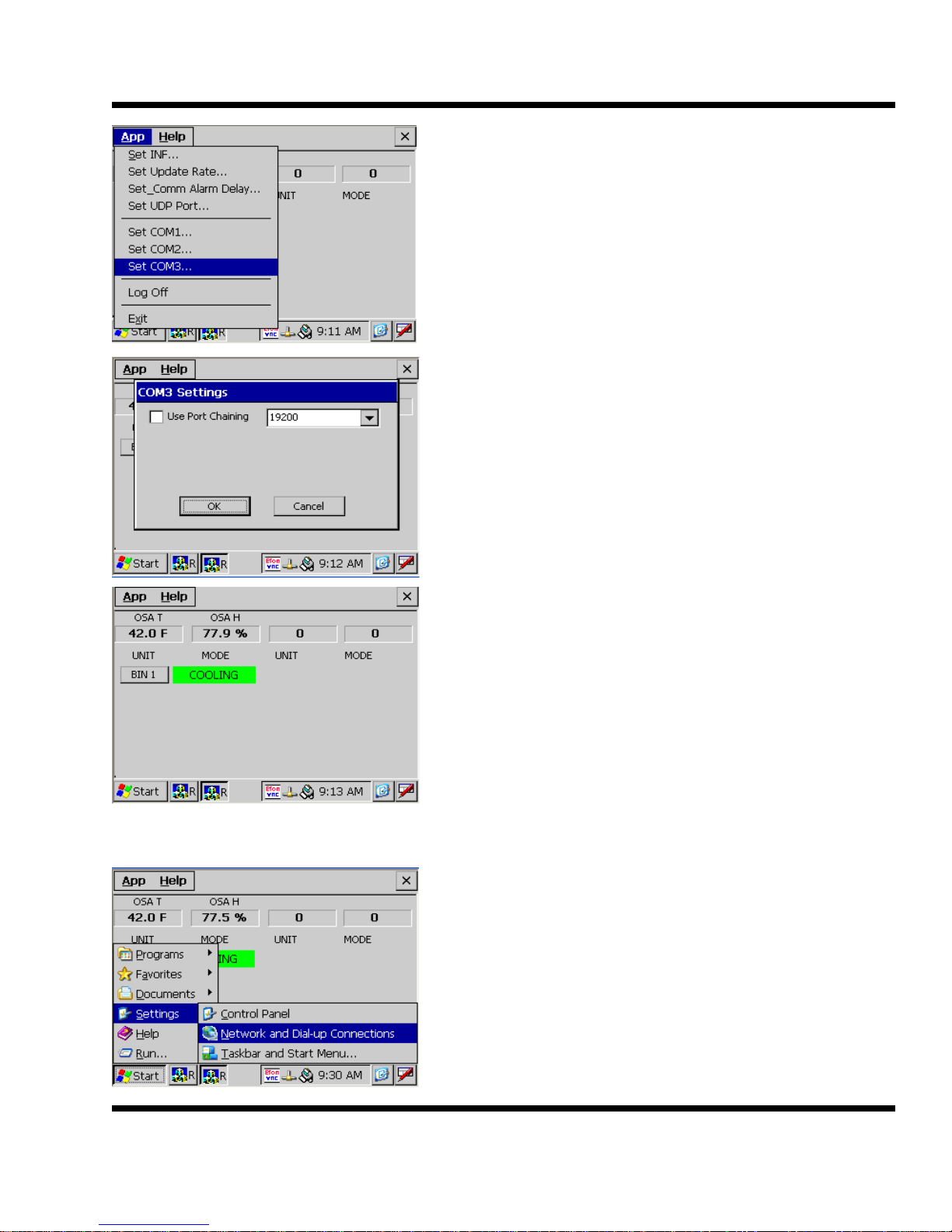
Tap on App and then on Set COM 3
Make sure that COM 3 is set for 19200
Tap on OK
The main display should be up and communicating.
Step 3: (IP address setup)
Tap on Start, Settings and then Network and Dial
up Connections.
BTU VENTILATION CORPORATION ● OFFICE 888-884-8070 ● FAX 218-346-7485 ● www.btuvent.com
Page 35
XT-Micro Control Panel 35
35
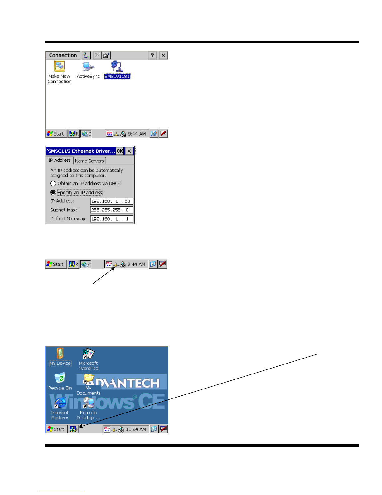
Double tap on the network icon SMSC91181
Tap on the Specify an IP address radio button.
Type in an IP address. Note - if the keyboard is in the
way, drag it above so the ip window is visible. Tap in the ip
window before typing.
Fill in the correct Subnet Mask and also the Default Gateway. The default gateway has to be the IP address of the
router.
Plug in a network cable and the network icon should become active.
Network icon
Step 4: (VNC Setup)
VNC is used for remote communications. It allows the user to view the TPC using a
web browser or VNC viewer on a cell phone.
At any time, the main program can be toggled to
full screen or minimized by tapping the icon.
BTU VENTILATION CORPORATION ● OFFICE 888-884-8070 ● FAX 218-346-7485 ● www.btuvent.com
m
Page 36
XT-Micro Control Panel 36
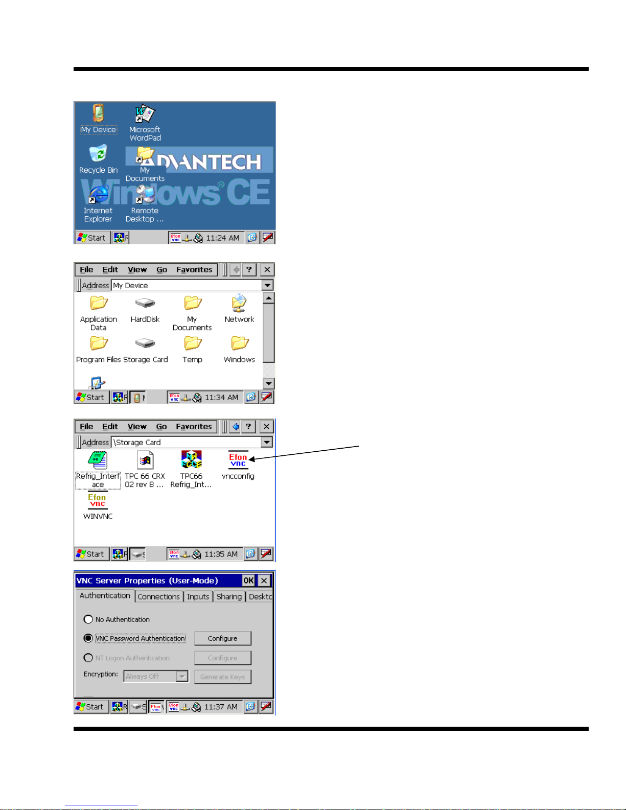
Minimize the control program by tapping on the icon.
Double tap on My Device.
Double tap on Storage Card
Double tap on the vncconfig icon
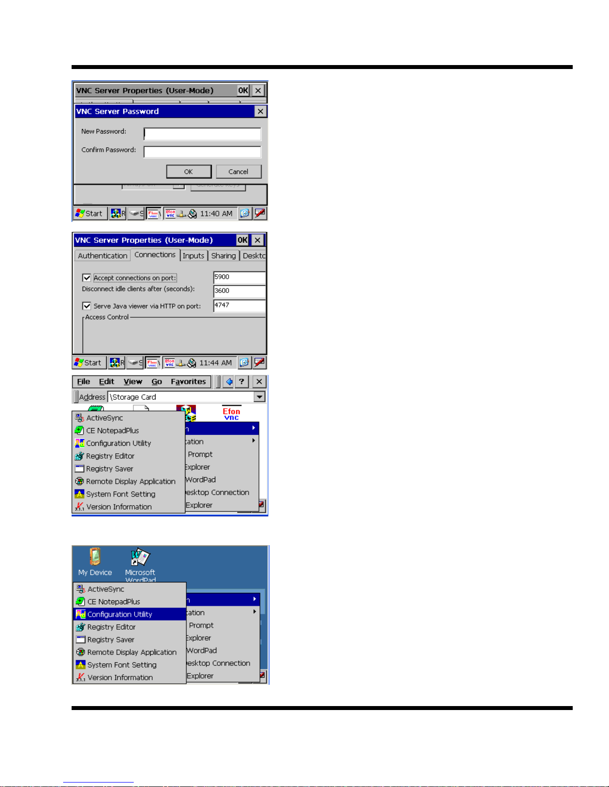
Make sure the VNC Password Authentication is
selected.
BTU VENTILATION CORPORATION ● OFFICE 888-884-8070 ● FAX 218-346-7485 ● www.btuvent.com
Page 37
XT-Micro Control Panel 37
37
Enter a password and then confirm the password.
Tap on the Connections tab and change the port
settings to match this example.
Move the keyboard if necessary to allow tapping
in the text window before typing.
Tap on OK
Tap on Start, Programs, Advantech and Registry
Saver.
Tap on X to close out the Storage Card directory.
Step 5: (VNC Start Up Menu)
Tap on Start, Programs, Advantech and Configuration Utility.
BTU VENTILATION CORPORATION ● OFFICE 888-884-8070 ● FAX 218-346-7485 ● www.btuvent.com
om
Page 38
XT-Micro Control Panel 38
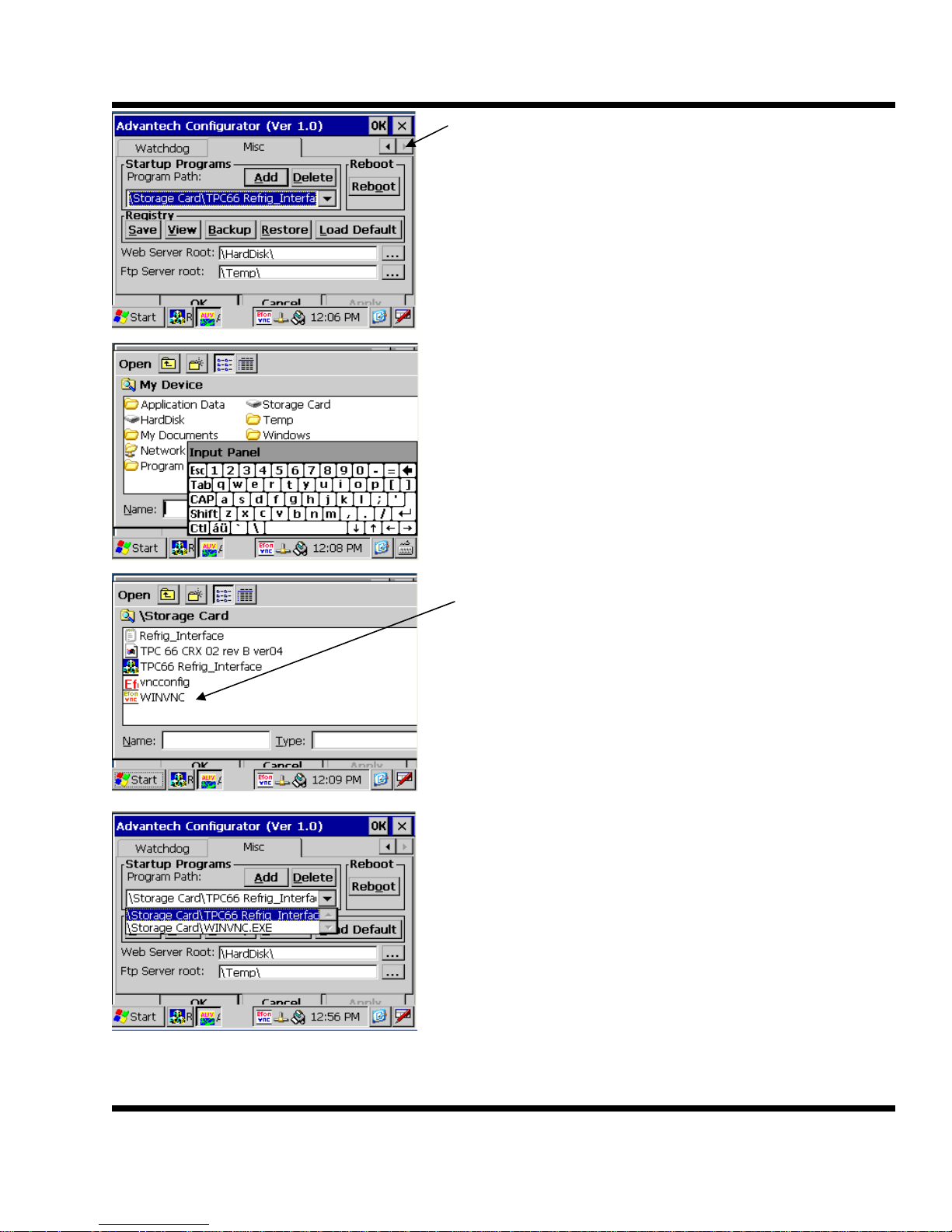
Tap on the right arrow to get to the Misc tab.
Tap on the Misc tab and then on the Add button.
Double tap on the Storage Card icon.
Double tap on the WINVNC incon.
The drop down should now have two entries. On
for the TPC 66 program and one for the WINVNC
BTU VENTILATION CORPORATION ● OFFICE 888-884-8070 ● FAX 218-346-7485 ● www.btuvent.com
Page 39
XT-Micro Control Panel 39
39
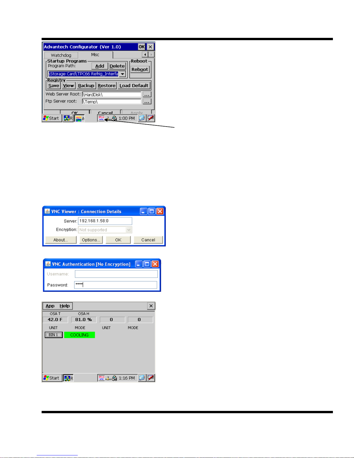
Tap on the Save Registry button to save the
change to the start menu.
Power the TPC down and back up. The VNC icon should auto start, just like the control program. The control program needs to be logged on each time it is started.
Step : (VNC Test)
In this example the TPC IP address was 192.168.1.58 and the VNC port was set to
4747. To access the TPC, use a web browser and go to http://192.168.1.58:4747
Click on OK.
Enter password
The VNC interface will allow full operation of the
TPC.
BTU VENTILATION CORPORATION ● OFFICE 888-884-8070 ● FAX 218-346-7485 ● www.btuvent.com
Page 40
XT-Micro Control Panel 40
To view the TPC using an iphone or other cell device, a VNC viewer will be needed as
most cell devices will not run java. A recommended viewer is Mocha VNC Lite.
Router Setup:
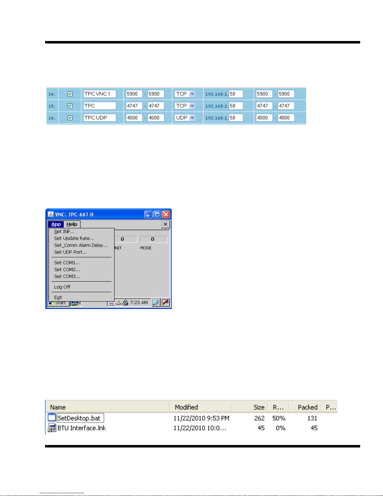
When setting up a router for access from the outside the port forwarding must forward
two ports. The 5900 port is used for security. The outside TPC access in this example
is port 4747. A third port forwarding statement is need for UDP access from the outside.
UDP Tunneling:
The TPC can be used for UDP tunneling allowing programs such as Zbase to access
any of the cards the TPC is communicating with.
Tap on App and then on Set UDP Port.
Start Icon for TPC Interface:
The operating system for the TPC will not allow the permanent creation of a icon for
the BTU interface. A way around this is to run a batch file that will temporally delete
some of the icons not used and add a BTU Interface Icon to the screen. This batch file
will run in the start up menu each time the TPC boots. It is composed of two files, the
actual bat file and a short cut file. These two files are on the tech web site under TPC
in the zipped file TPC Desktop Icon.zip. Down load these files and unzip them.
BTU VENTILATION CORPORATION ● OFFICE 888-884-8070 ● FAX 218-346-7485 ● www.btuvent.com
Page 41
XT-Micro Control Panel 41
41
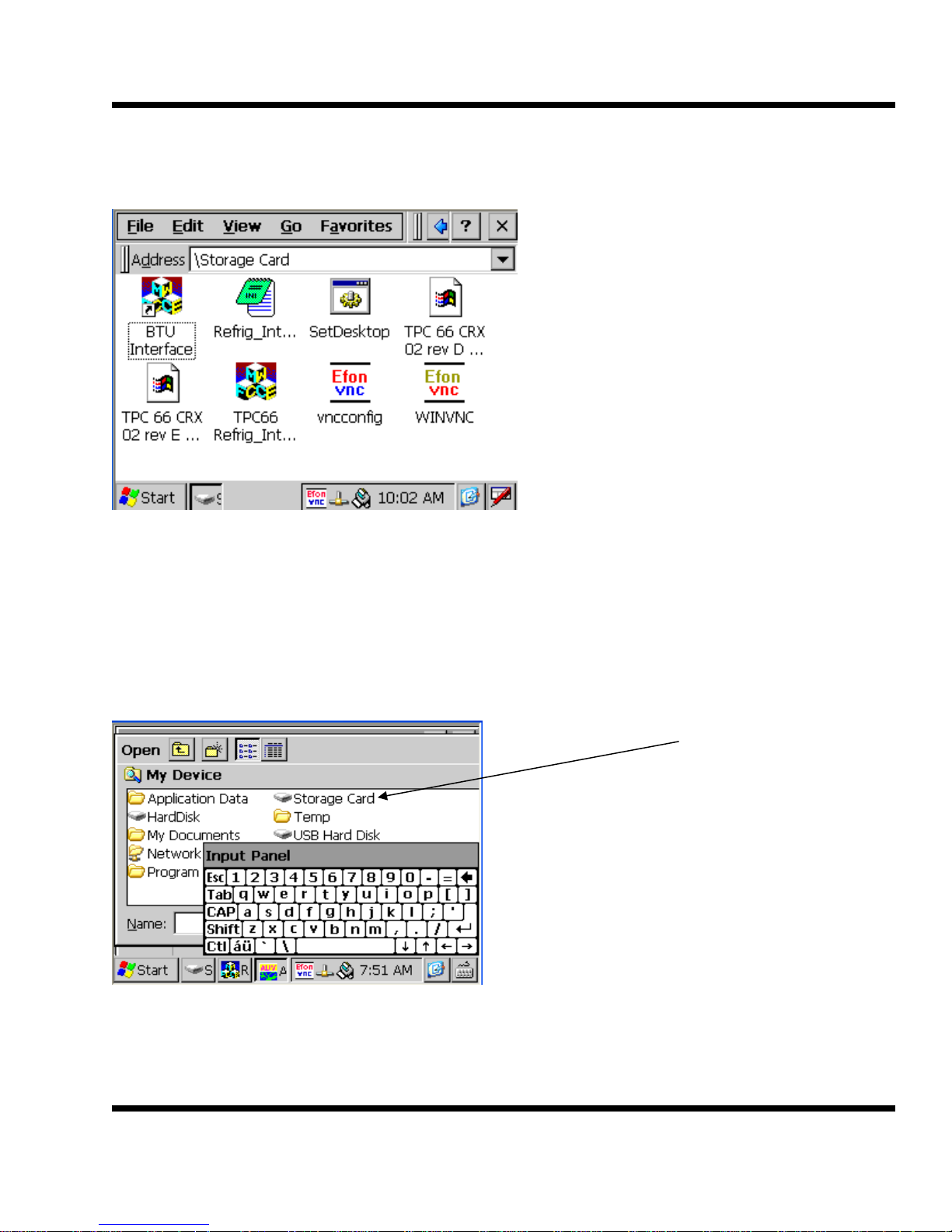
These files need to be copied onto the Storage card of the TPC. Use the same procedure as outlined starting on page 28. Once you copy the files your storage card should
look similar to this: The two new files are BTU Interface and SetDesktop.
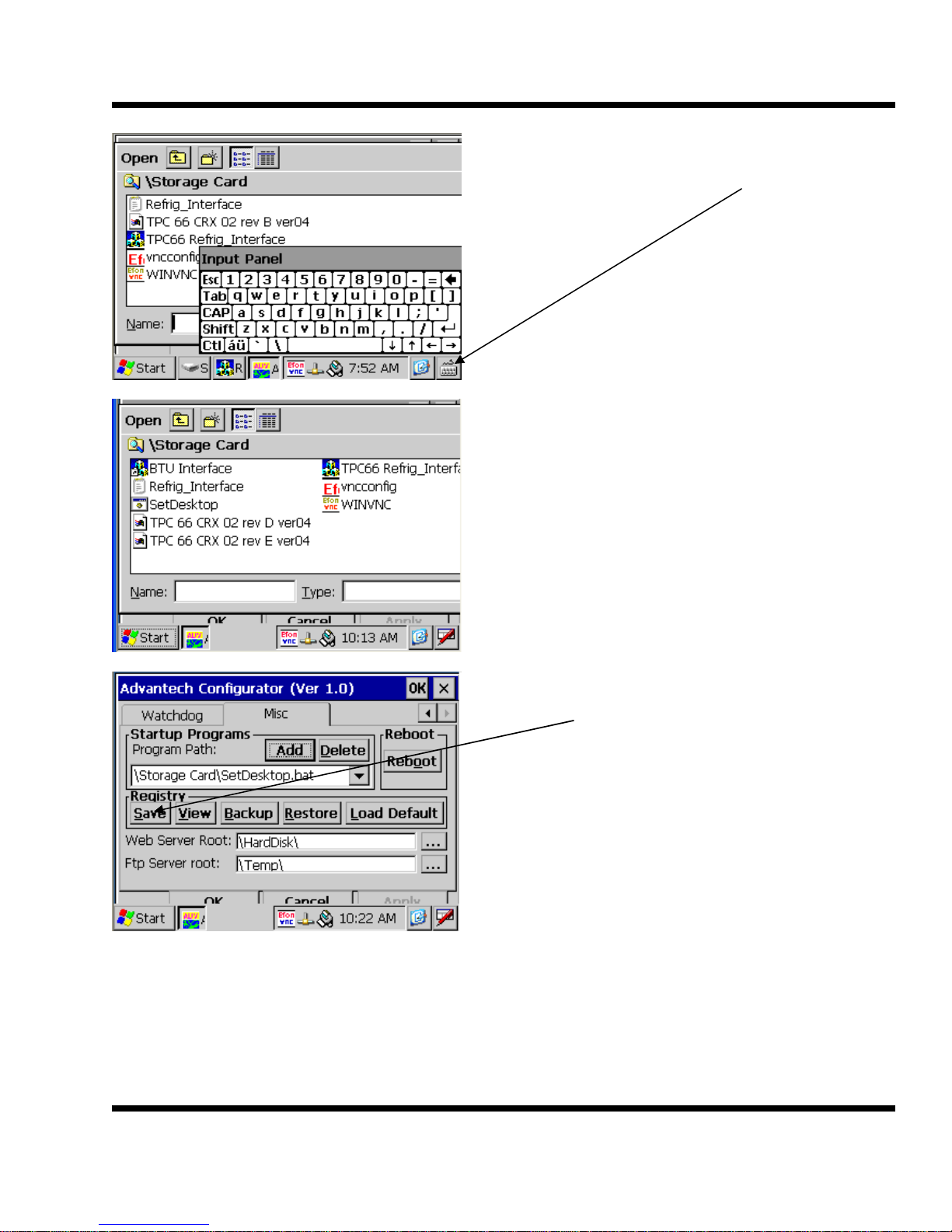
Next the SetDesktop file needs to be added to the Startup menu. Repeat the steps
outlined on page 31, under step 2. Click on the Add button.
Double tap the storage Card
BTU VENTILATION CORPORATION ● OFFICE 888-884-8070 ● FAX 218-346-7485 ● www.btuvent.com
Page 42
XT-Micro Control Panel 42
Tap on the keyboard icon and then on hide
input panel to remove the keyboard.
Double tap on the SetDesktop file.
Tap on the Registry Save button to save the
start up menu.
Top on OK to exit configurator.
Power the TPC down and back up. It should start the BTU interface automatically and
also run the batch file. Exit out of the BTU interface program and there should be a
BTU interface shortcut on the desktop.
BTU VENTILATION CORPORATION ● OFFICE 888-884-8070 ● FAX 218-346-7485 ● www.btuvent.com
Page 43

XT-Micro Control Panel 43
43
Double click on the BTU interface icon
and the program should start.
Note - this procedure is currently only for the TPC 66. The files would need to be
changed for the TPC 30.
BTU VENTILATION CORPORATION ● OFFICE 888-884-8070 ● FAX 218-346-7485 ● www.btuvent.com
 Loading...