

Page 1

User/Installation Guide
GSM STU EV
Page 2
CE MARKING
The GSM* STU* carries the CE approval marking in accordance with the CE
Marking Directive 93/68/EEC. The GSM STU EV complies with the following
European Directives:-
73/23/EEC (Low Voltage Directives)
by compliance with safety specifications:-
EN60950 User Safety
EN41003 Network Safety
89/336/EEC (Electro Magnetic Compatibility Directive) as amended by 92/31/EEC
by compliance with EMC specifications:-
EN55022 Emissions Class B
EN50130-4 Immunity
99/5/EEC (Radio and Telecommunications Terminal Equipment Directive)
2002/96/EC (Waste Electrical and Electronic Equipment Directive)
Suitable for use in systems that comply with EN 50131-1 at:
Security Grade 4, Environmental Class 1.
* GSM = Global System for Mobile communications
* STU = Subscriber Terminal Unit
Page 3

Table of Contents
INTRODUCTION 3
Static Sensitive Devices 3
Decommissioning Procedure 3
GSM STU EV OVERVIEW 5
Specifications 6
GSM STU Compatibility 7
3GSTU Replacement 7
Redcare GSM Connection 7
Safety Statement 7
Siting 8
Power Supply 8
Line Compatibility 9
REN 9
INSTALLATION 11
Training Courses 11
Pre-installation Requirements 11
CPE Number 11
Connecting The Telephone Line And Earth 12
Antenna 13
Mains Fail 15
Tamper 15
Power Connection 15
Alarm Inputs 15
Plug-in Compatibility Link (Lk3) 17
Output Relays 17
Control Output 18
Return Path Signalling Output (RPS) 18
Line Fault Relay 18
ATS Test 19
Telephone Line Selection (Lk1) 19
NVM 21
Remote Programming 22
Pin Alarm Polarity 23
Learning Procedure 23
Programming The NVM 26
STATUS INDICATORS 32
STU Status LED Meanings 33
SYSTEM COMMISSIONING 36
Testing The System 36
Warranty 37
Repairs 37
TROUBLESHOOTING 38
Chirps 38
Substitution 38
Equipment Compatibility Issues 38
DISPOSAL 43
Page 4

Introduction
Static Sensitive Devices
Static electricity is present in our everyday lives. A static charge is generated by friction and the separation of two
dissimilar materials. An imbalance of electrons causes a potential difference of many hundreds of volts. On discharge, a
large current flows for a short time.
Many electronic components can be damaged by such static charges. Component failure may not be immediate or
catastrophic. Electro-Static Discharge (ESD) can cause hidden damage to components, which will affect their reliability.
It is recommended that precautions are taken against damage due to static electricity during the installation and
maintenance of the GSM STU EV. Suitable ESD protection measures include ensuring that you are earthed (via a wrist
strap and a 1 MΩ resistor) whenever you handle the unit.
Decommissioning Procedure
Important:
If the GSM STU EV is in service, the Alarm Receiving Centre (ARC) must be contacted to decommission it before it is
power cycled. You must follow these decommissioning instructions when there is a need to change the alarm system
settings:
1. Call the ARC and request they decommission the GSM STU EV.
2. Wait for the ARC to confirm that the GSM STU EV is decommissioned.
3. Turn off the power to the alarm system completely (i.e. switch off the mains and disconnect the battery).
4. Make the desired changes to the alarm system.
5. Re-connect the battery and switch on the mains to re-apply power to the GSM STU EV.
6. Request the ARC re-commission the GSM STU EV.
7. Test the system (see page 36).
Page 3
Page 5

GSM STU EV Overview
Page 6

GSM STU EV Overview
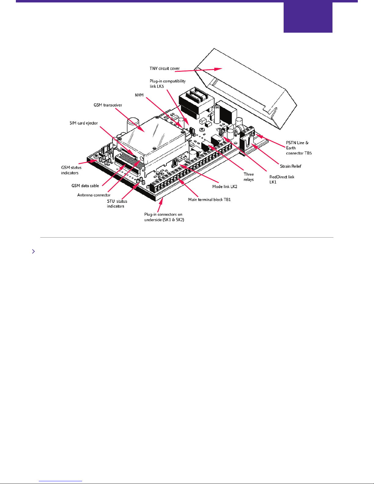
The GSM STU EV is a combined Public Switched Telephone Network (PSTN) Subscriber Terminal Unit and wireless alarm
reporting device for the redcare gsm service.
The GSM STU EV system is designed to provide a backup communications path for the single landline connection to a
premises. This allows alarms to continue to be transmitted even in the event of a landline communications failure.
The Alarm Receiving Centre (ARC) will be able to continue to monitor a premises following a landline cut. It also allows line
faults (as distinct from malicious line cuts) to be more positively identified. A malicious line cut will usually be accompanied
by an intruder alarm transmitted over the GSM path.
In addition, the GSM signal strength is constantly monitored. Should this fall below a certain level, an alarm message will
be transmitted via the landline indicating that there is a GSM fault.
During normal operation, the GSM path does not pass any data and all signalling is via the BT landline.
The GSM link becomes active:
• During the GSM STU EV commissioning sequence.
• If the GSM STU EV detects a landline communications failure.
• When the landline has failed and a pin alarm occurs.
• When a routine GSM connection test is being performed.
• If a message transmitted across the landline is not acknowledged
Page 5
Page 7
Specifications
Power supply requirements:
Voltage: 10 V DC to 15 V DC
Current: 350 mA peak @12 V DC (Required rating of power supply)
160 mA mean @12 V DC (For standby battery capacity)
Ripple/noise: 200 mV p-p max.
Low battery threshold (detected by GSM STU EV): 10.8 V ± 0.2 V
Pin alarm inputs:
Logic High = +3.5 V to +30 V
Logic Low = -0.5 V to +0.8 V
Logic level outputs: (on sockets SK1 and SK2)
Logic High = 3.8 V @ 560 μA max
Logic Low = 0.4 V @ 280 μA max
These voltages are with respect to the 0V terminal on TB1
Relay contacts:
30 V, 1 A Max
Page 6
GSM STU EV
Page 8

Physical:
Size = 168 x 115 x 36 mm
Mass = 360 g
Environmental:
Operating ambient temperature +5° C to +40° C
GSM STU compatibility
For instances where the GSM STU EV is required to behave in an identical fashion to a GSM STU, the NVM should be
removed and the link LK3 be fitted to position P16. This mode of operation disables the ATS test functionality and
permits pin inputs 10 and 11 to be used if required.
3GSTU Replacement
The GSM STU EV has been designed as a replacement for existing 3GSTU installations where there is a need to upgrade
the line to incorporate GSM backup. For a 3GSTU-12V any existing alarm pin wiring or power connections can be
re-used. These terminals are in the same relative positions as they are on the 3GSTU. Any existing power supply needs to
be adequate, see page 6. Care must be taken when replacing a 3GSTU-PLI because of the slight differences in the
plug-in connector pin-out (see page 15).
Redcare GSM Connection
redcare gsm requires that the designated ARC be connected to the redcare Digital Services Platform (DSP).
Safety Statement
The circuit board area, under the cover, is classed as a Telecommunication Network Voltage (TNV-3) circuit. All other
interconnection points are classed as Safety Extra-Low Voltage (SELV) circuits. It is only necessary for this cover to be
removed during installation of the PSTN wiring. A protective earth connection is required to the terminal block TB5.
GSM STU EV is designed for host-independent fitment.
The host alarm panel or box into which the GSM STU EV is installed must provide a RESTRICTED ACCESS LOCATION and a
FIRE ENCLOSURE in accordance with the requirements of BS EN 60950.
It is essential that the GSM STU EV is installed so that there is a gap of at least 5mm between it and any other part of
the host equipment (excluding the mounting face). If any part of the host apparatus uses or generates voltages in excess
of 250 V rms or dc, obtain advice from a competent telecommunications safety engineer before you install
the GSM STU EV.
Page 7
Page 9
Siting
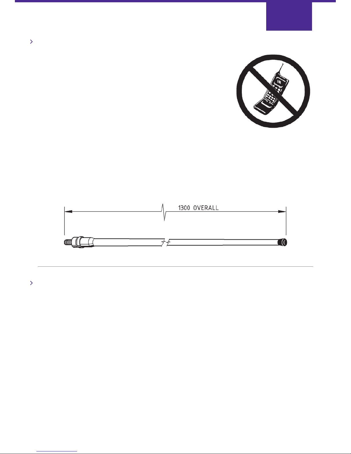
When surveying the site please remember that the GSM STU EV operates in a
similar way to an ordinary mobile telephone, therefore any restrictions
on the use of mobile telephones in the area will also apply to the GSM STU EV.
Premises such as hospitals, petrol stations, airports, blasting areas etc. may operate
a mobile telephone restriction in certain areas. Always ensure that the chosen site
is free of any mobile telephone restrictions and advise the end user so that they are
aware, should any restrictions come into force in the future.
It is useful to perform a signal strength test during a pre-installation site visit.
This task requires the use of an O2 connected digital GSM mobile telephone.
To perform a GSM signal strength test:
1. Determine where the GSM STU EV enclosure will be eventually situated.
2. Place the phone where the GSM STU EV is to be installed, switch it on and observe the signal strength.
If the signal strength is weak, try to find a better position for the GSM STU EV. If required, higher gain extension
antennas and extension cables are available at extra cost. For further information, contact BT redcare products, telephone
number 08702 400 503.
Power Supply
The GSM STU EV must be connected to a suitable power supply. The installer must ensure that the rating of the power
supply is greater than the combined rating of the GSM STU EV and any other apparatus drawing power from the
power supply.
The GSM STU EV supply requirements are detailed on page 6.
Page 8
Page 10

Line Compatibility
The GSM STU EV is designed for connection to either the Public Switched Telephone Network (PSTN) or a Private Wire
(RedDIRECT). It is also compatible with earth calling lines.
It is NOT to be used with 1+1 carrier systems or a shared service.
The GSM STU EV must NOT share a telephone line with other electronic data equipment, such as a facsimile machine,
EPOS terminal or digital communicator unless a redcare Modem Compatibility Device (MCD) is used.
(MCD cannot be used with Private wire or Earth Calling lines.)
Only one GSM STU EV may be connected to any one telephone line.
REN
The Ringer Equivalence Number (REN) for the GSM STU EV is 1.0. As a guide to the number of apparatus that can be
simultaneously connected to a line, the sum of REN values for each apparatus should not exceed 4.0. A BT provided
telephone is assumed to have a REN value of 1.0 unless otherwise marked. If the GSM STU EV is used with an MCD, the
combined REN will be 1½.
Page 9
Page 11

Installation
Page 12
Installation
Training Courses
BT redcare offer a free training course for installers of the redcare gsm service. For further information call General
Enquiries Tel: 0800 800 828
Pre-Installation Requirements
Before a GSM STU EV installation can commence, a redcare Service Order must be submitted to BT redcare by the Alarm
Receiving Centre. This ensures that the appropriate exchange connections have been made and a redcare block
terminal 92A has been provided, if required, at the customer’s premises.
CPE Number
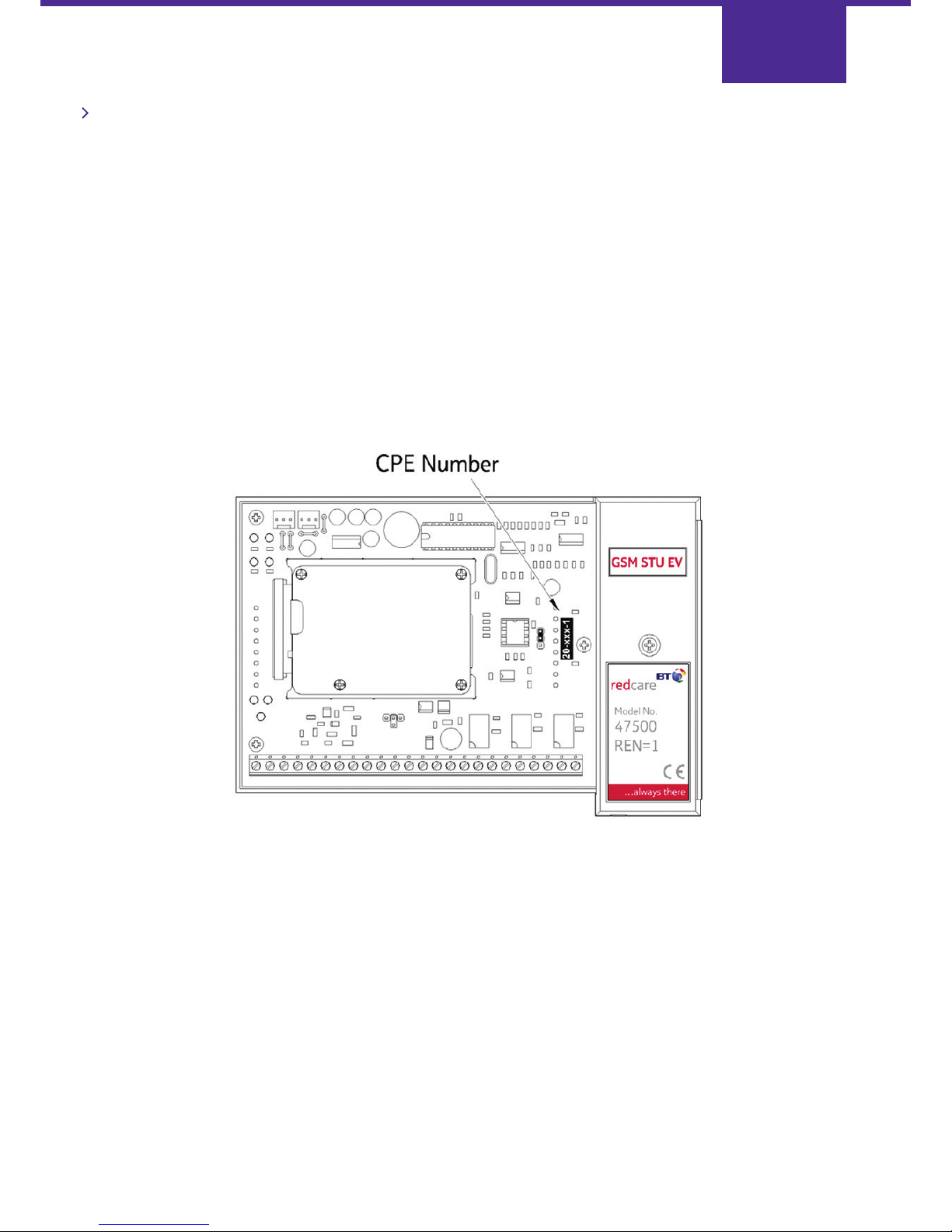
The CPE (Customer Premises Equipment) number of the GSM STU EV must match that on the redcare service order
allocated to the premises. The CPE number can be found on the outer GSM STU EV packaging as well as on the
GSM STU EV circuit board itself (see below).
BT redcare maintain a database of the unique CPE numbers matched to the associated PSTN telephone number and the
mobile phone number of the GSM unit. For this reason the SIM card in the GSM unit cannot be changed or used in
any other installation.
Page 11
Page 13
Page 12
Important:
THE ALARM SYSTEM MUST BE TOTALLY POWERED DOWN
(SWITCH OFF MAINS AND DISCONNECT THE BATTERY)
BEFORE INSTALLATION CAN COMMENCE.
For certain alarm panels, the GSM STU EV can be directly mounted using the
"Plug-in" connections available. Locate it on the two 8-way connectors on the
control panel circuit board. Take care to align the pins to the sockets on the
board correctly: if they are out of alignment, damage may occur.
For other alarm panels and installations where “Plug-in” connections are not
available, the unit can be wired “stand-alone”. Ensure that the supplied mounting
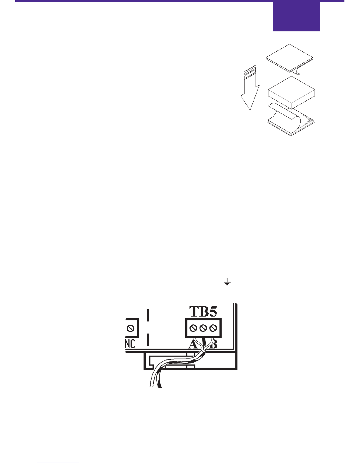
blocks and the GSM STU EV base are free from dust or grease. Bond the double-sided
adhesive pads to each side of the blocks as shown, and affix them to the underside of
the GSM STU EV. The assembly can then be fitted onto a clean, flat surface within the host enclosure.
Care must be taken when connecting wires to the main terminal block TB1 and the telephone terminal block TB5.
The small screws can be easily damaged by over-tightening. Wiring connected to terminal block TB1 should be kept as
short as possible to reduce the likelihood of RF pickup.
Connecting the Telephone Line and Earth
The TNV circuit cover of the GSM STU EV should not be removed whilst the unit is connected to the PSTN or
Private Wire network.
Remove the TNV circuit cover from the GSM STU EV.
Use two core telephone cable (type: 1/0.5 mm CW1308) that is not yet connected to the PSTN or Private Wire (PW)
network. Strip back the insulation so that 5 mm of wire conductor is exposed. Position the cable in the plastic base as
shown on page 12. Connect one core to the terminal marked A and the other to the terminal marked B.
Strip back an earth cable (green/yellow, core area greater than 1mm²) so that 5mm of wire is exposed. Position the cable
in the plastic base as shown on page 12 and connect it to the terminal marked
The other end of this cable must be connected to a good electrical earth.
Failure to fit an earth cable will prevent proper operation of the unit and will invalidate the warranty.
Replace the TNV circuit cover and secure in position with the screw.
Page 14
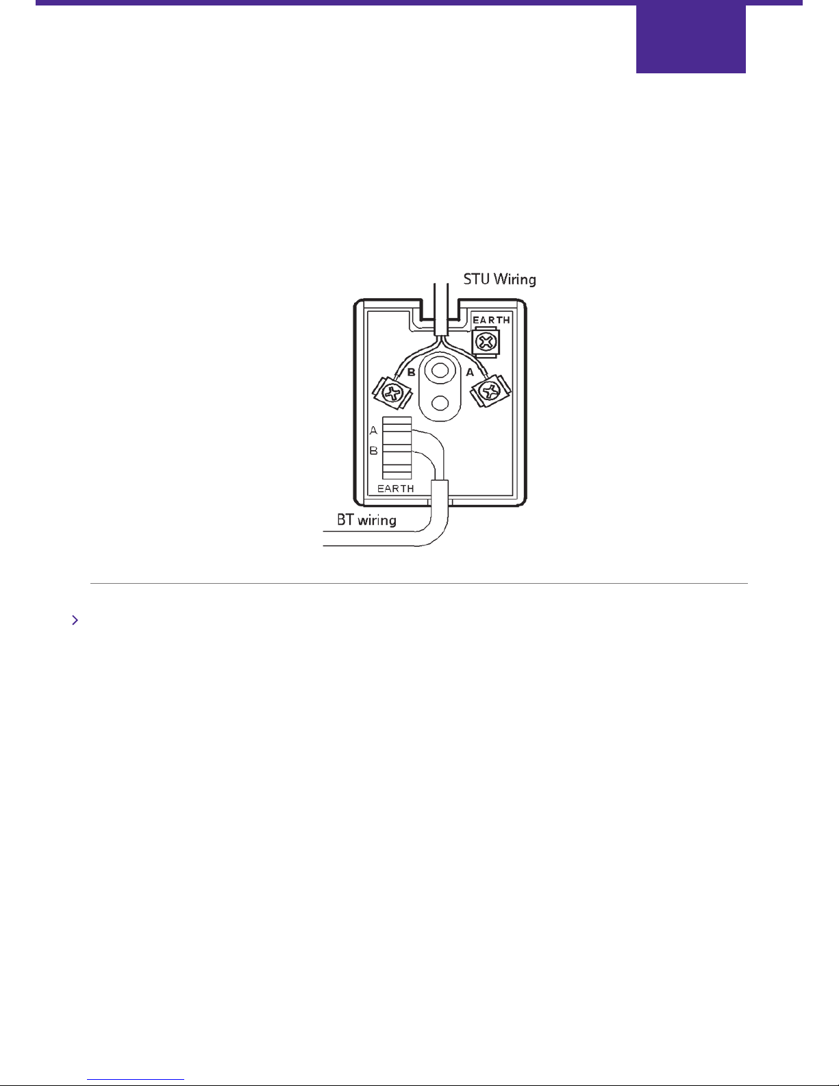
Take the opposite end of the two core telephone cable and strip back both cores so that 5mm of wire is exposed.
Connect both wires to the redcare block terminal.
WARNING: the block terminal contains telecommunication network voltages.
Please note that it is important to use the correct method of connecting the STU to the BT Block Terminal 92A.
The Block Terminal provides an insulation displacement connection (IDC) block for the incoming phone line.
No connections, other than those made by BT, should be made to this IDC block. The GSM STU EV should be connected
to the screw terminals as shown.
Antenna
Note: The antenna will emit Radio Frequency radiation in the same way as that of a mobile phone.
The antenna provided is a flat type (115 x 65 x 17mm) and must be mounted indoors, on a flat horizontal surface,
sufficiently close that it can be connected to the GSM STU EV. The antenna is self-adhesive and will bond firmly to any
clean, dry and flat surface. Make a suitable hole, (typically 11mm diameter) in the top of the box in which the
GSM STU EV is fitted. Prevent swarf from entering the enclosure as it could cause internal short circuits.
Remove any burrs from the hole, pass the RF cable through it and place the antenna in position. It is advisable not to
bond the antenna onto the box at this stage. Wait until the system has been tested, as it is difficult to remove once
attached.
Page 13
Page 15
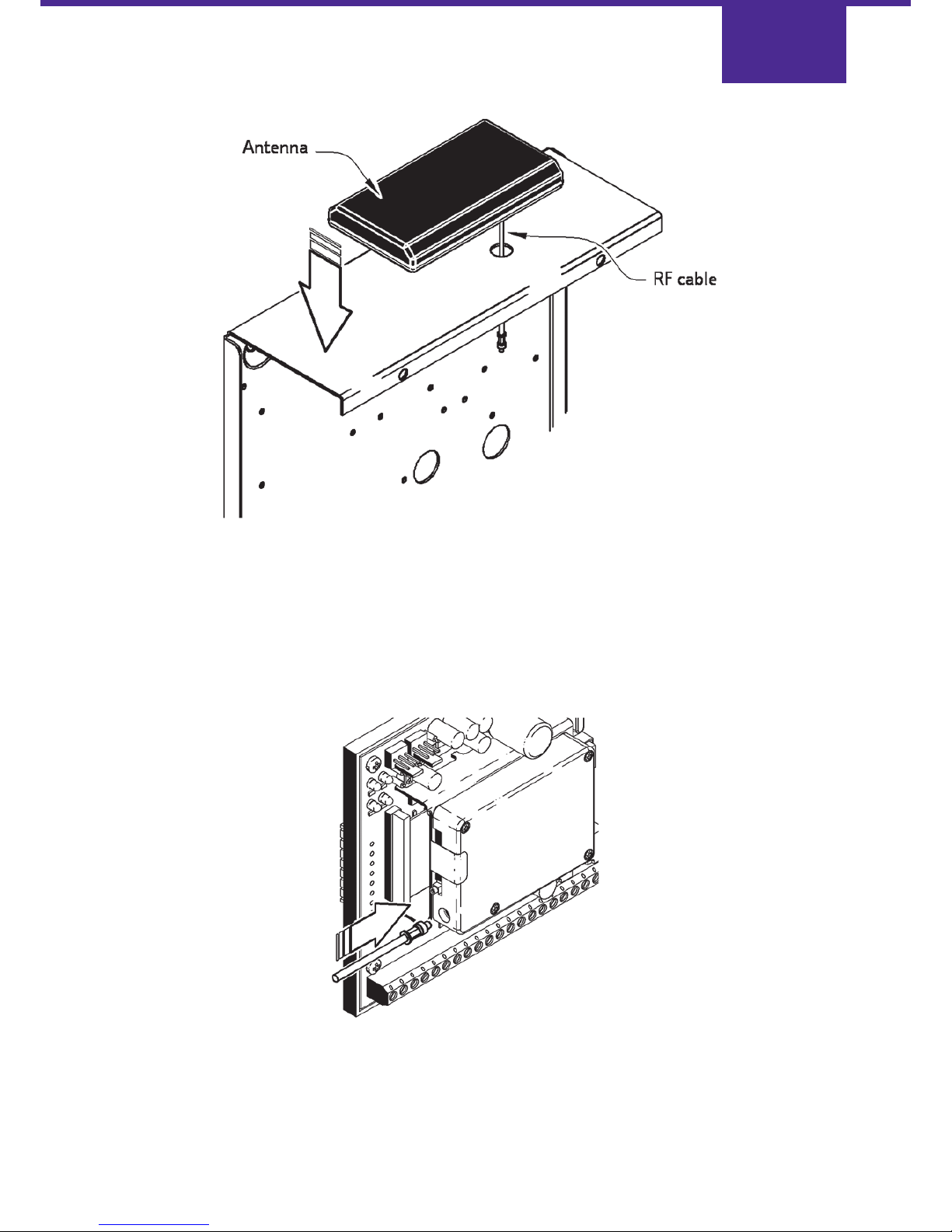
Try to route the RF cable away from any other wiring within the box to reduce the likelihood of interference.
Carefully connect the RF cable to the GSM module on the GSM STU EV. The connector is a micro-miniature co-axial
(MMCX) screened type and is easily damaged. The connector has a positive locking device and will
click when correctly mated.
Page 14
Page 16

Mains Fail
If an AC fail signal is provided from the power supply, this should be connected to the terminal marked F on TB1.
Tamper
If a tamper signal is provided this should be connected to the terminal marked T on TB1. The tamper alarm can also be
generated and sent to the ARC if the GSM STU EV itself detects a tamper, such as the removal of the NVM.
Power Connection
As stated at the beginning of the Installation section, the power supply must be totally powered down
(switch off mains and disconnect the battery) before making these connections.
For both plug-in and stand-alone installations, the power must always be provided to the screw terminals at TB1.
The power supply must be arranged such that the GSM STU EV is powered simultaneously to, or before, the alarm panel
to which it is connected.
DAMAGE CAN OCCUR IF THE ALARM PANEL IS POWERED AND THE GSM STU EV IS NOT.
The supply to the GSM STU EV must be provided by hard wiring the TB1 screw terminals to a suitable power
source. Connect +12V to the terminal labelled V+ and 0V to the terminal labelled 0V. This power wiring must be less
than 3m in length and use wires having core areas of at least 1mm2. The GSM STU EV will take a peak current of 350mA
from the 12V supply, when the GSM transceiver is in operation. The current consumption otherwise is typically 160 mA.
Alarm Inputs
For “Plug-in” installation, alarm pin connections are made automatically whenthe GSM STU EV is plugged in to the
host alarm panel. When fitting the GSM STU EV, check that the signals presented by the alarm panel match those
required by the STU, for the two sockets SK1 and SK2. The pins have been designated the following functions on
the GSM STU EV:
For plug-in installations, be sure that no wires are ever connected to the terminals 1 to 8 on TB1. Terminals 9, T & F
can be connected if these channels are required in addition to those present on the plug-in connectors (SK1 & SK2).
For stand-alone installations, alarm input terminals on terminal block TB1 must be connected to the alarm panel outputs.
Unused channels can be left unconnected.
The TB1 terminal marked is reserved for GSM failure, and the ATS Test function in accordance with BSIA form 175.
Page 15
Page 17

Note: If ATS Test is used by the panel on the plug-in connector, it must be linked to alarm 8 using the jumper at LK3 in
position P11.
Terminal Block TB1 Alarm Channel Configuration
Page 16
SK1 Function SK2 Function
Pin 1 Alarm Input 1 Pin 9 Not Used
[+12V on 3GSTU]
Pin 2 Alarm Input 2 Pin 10 Signal Ground
[0V supply on 3GSTU]
Pin 3 Alarm Input 3 Pin 11 ATS Test (via LK3)
Pin 4 Alarm Input 4 Pin 12 Not Used
[+5V on 3GSTU]
Pin 5 Alarm Input 5 Pin 13 Alarm Input 6
[5 or 7 on 3GSTU) [Not used on 3GSTU]
Pin 6 Tell Back (output) Pin 14 Alarm Input 7
[Control Output on 3GSTU [Alarm 6 on 3GSTU]
Pin 7 Comms Fail (output) Pin 15 Line Fault (output)
[Not used on 3GSTU]
Pin 8 Low battery (input) Pin 16 Alarm Input 8 via LK3
Chan. No. TB1 Ident Function
1 1 Fire
2 2 Hold Up Alarm
3 3 Intruder
4 4 Opening / Closing
5 5 Zone Omit
6 6 Optional
7 7 Confirmed
8 GSM fail / ATS Test (reserved)
9 9 Optional
10 10 ATS GSM Test (reserved)
11 11 ATS Landline Test (reserved)
12 T Tamper
13 F AC Fail
Page 18
Plug-in Compatibility Link (LK3)
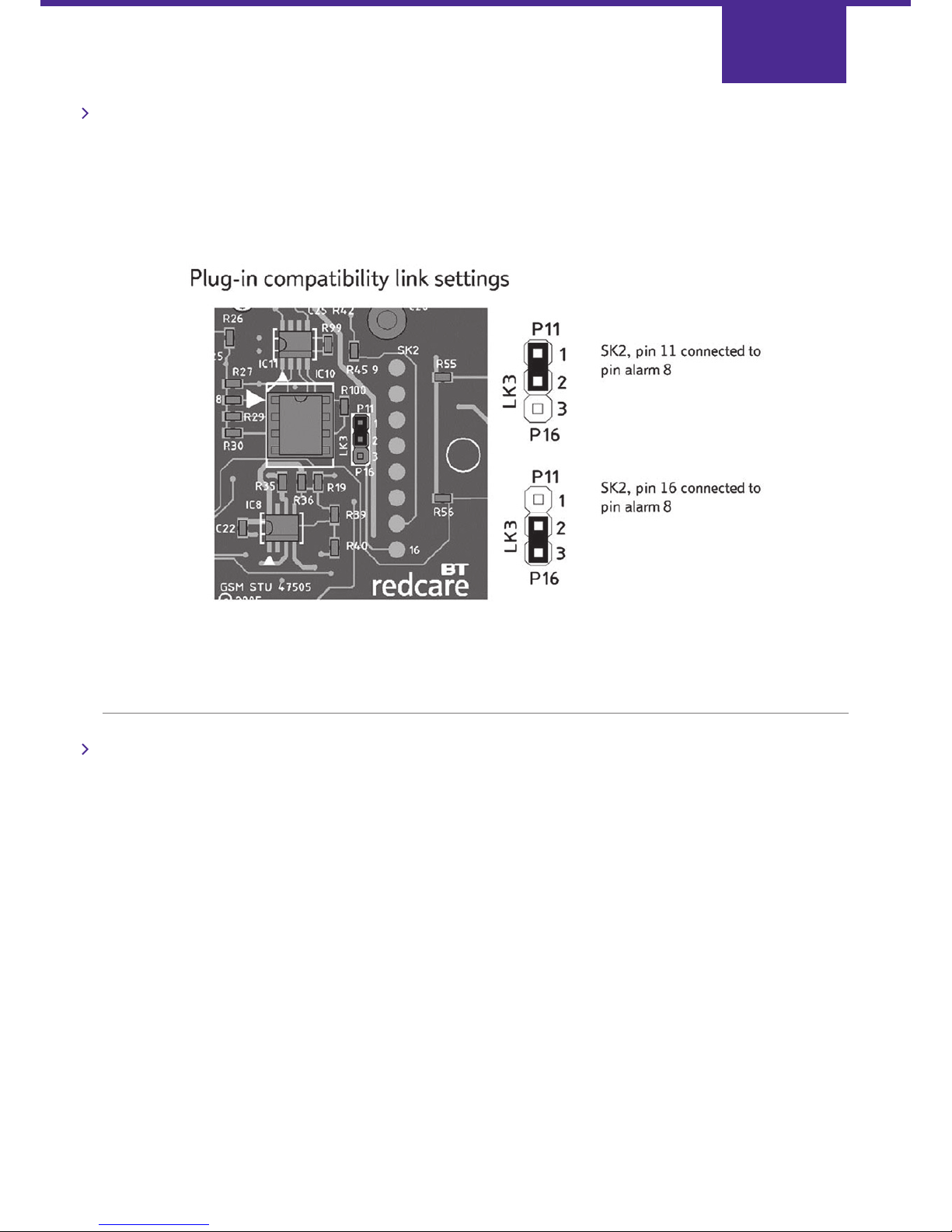
Some newer alarm panels use pin 11 as the ATS Test function on the plug-in connectors, whilst older panels may use pin
16 as alarm 8. GSM STU EV is supplied with an NVM (IC10) programmed and fitted to enable ATS Test mode
(see page 18). The jumper, at LK3, is fitted as supplied, to enable compatibility with plug-in panels using the ATS test
feature (SK2, pin11 connected to pin alarm 8 for ATS test).
Set the jumper in the lower position for use with older plug-in panels that use SK2, pin 16 as alarm 8. For stand-alone
(wired) installations the setting is irrelevant.
Output Relays
Three output relays are provided: Control, Return Path Signalling (RPS), and Line Fault.
Note: If an output is to be connected to a device which produces transient voltages, such as a bell, the device should be
suppressed using a suitable protection diode. Each relay’s contacts (Normally Open, Common, Normally
Closed) are available for connection on terminal block TB1. The relay contacts have a maximum current rating of 1 Amp.
GSM STU EV can be programmed to indicate communications path failures in different ways. Available options include
the Line Fault Relay indicating that both paths have failed (default); the Line Fault Relay indicating that one of the two
paths have failed; or landline and GSM path failures may be indicated on a combination of two of the three available
relays. These alternative modes of operation are not suitable for a GSM STU EV used as a plug-in.
Page 17
Page 19
Control Output
The Control Output can be used as a general purpose output which is controlled by the Alarm Receiving Centre. It may be
used for various functions including the remote resetting of alarm panels. Additionally, this relay can be used in
conjunction with the Line Fault relay to indicate discrete communication path fails at the protected premises (in this
mode, the Control Output relay is no longer controlled by the ARC)
For plug-in installations, Control Output connections are made automatically when the unit is fitted in the host alarm
panel. The host alarm panel must be programmed to enable this function (TELL BACK).
Return Path Signalling Output (RPS)
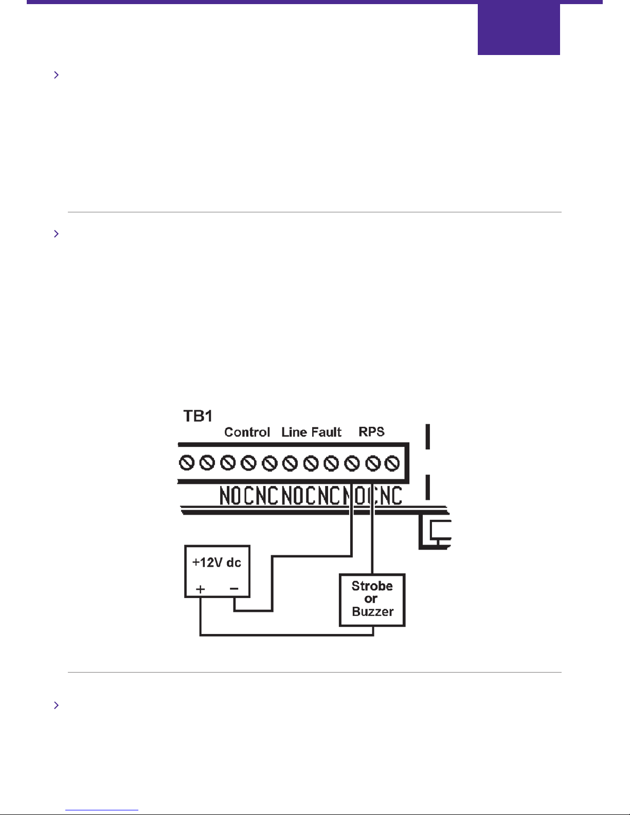
The RPS output is used to indicate, at the protected premises, that the opening/closing signal has been sent to and
acknowledged by the Alarm Receiving Centre.
To use the RPS function, one of the alarm inputs must be designated as an opening/closing channel (usually channel 4).
The RPS output will activate when an opening or closing signal is detected. It will de-activate when the opening or
closing signal has been acknowledged by the Alarm Receiving Centre. It is allowable to have more than one input
designated as an opening/closing channel, but each must be acknowledged to de-activate the RPS output.
To use this option, a warning device such as a piezo bleeper or external strobe light should be connected as shown below.
The maximum current rating of the relay contacts is 1 Amp.
Line Fault Relay
The Line Fault Relay is used to indicate, at the protected premises, that one or both, the GSM and landline (PSTN or
Private Wire) communication paths have failed. For plug-in installations, Line Fault connections are made automatically
when it is fitted into the host alarm panel. The host panel must be programmed to accept this function.
Page 18
Page 20

ATS Test
The GSM STU EV is supplied with an NVM fitted, which enables the Alarm Transmission System test function. The ATS test
function allows the alarm panel (and ARC) to distinguish whether one or both paths have failed in the event of a
communications failure. The Line Fault signal (SK2 pin 15 or the Line Fault relay), and the ATS test signal (SK2 pin 11 or
Alarm Pin 8 on TB1) are used in accordance with BSIA form 175. This is available free of charge from the BSIA or
downloadable at:
http://www.bsia.co.uk/pdfs/Form_175.pdf
The alarm panel must also conform to this standard for the function to work correctly. The alarm panel can request an ATS
test by applying the ATS Test signal, the GSM STU EV then communicates with the ARC on both the GSM wireless path
and the landline. If no communication path faults are detected by the GSM STU EV, the ARC will receive a pin alarm 10
over the GSM path and a pin alarm 11 over the landline. When reset, these will complete the end-to-end test.
If the alarm panel asserts the ATS test pin/channel during a line fault the GSM STU EV will signal to the alarm panel
whether it is a dual path or single path failure in accordance with BSIA form 175, using the line fault output and relay.
To deactivate the ATS test function, the plug-in NVM can be carefully removed or re-programmed to suit (see page 21).
For plug-in panels, LK3 may also have to be changed (see page 17).
Telephone Line Selection (LK1)
The GSM STU EV is supplied ready to connect to the Public Switched Telephone Network (LK1 is not fitted).
If the GSM STU EV is to be connected to a Private Wire (RedDIRECT) a suitable link must be fitted in the position marked
LK1. An NVM chip must be configured for PW use and fitted in accordance with the procedure on page 21.
If you have any doubts about the type of telephone line to which the STU is being connected,
contact BT redcare for advice.
Page 19
Page 21

NVM
Page 22
NVM
The NVM (Non-Volatile Memory) chip is an optional device used by the GSM STU EV to store configurable
parameters. This memory is retained even when the power is completely removed.
The GSM STU EV contains a factory default configuration stored in its permanently fitted EEPROM (Electrically Erasable
Programmable Read Only Memory). The default configuration (with no NVM fitted at IC10) is:
PSTN with line monitoring.
Control Relay not energised at power up and managed by the ARC.
Line Fault Relay energised and plug-in Line Fault signal asserted on failure of both communication paths.
Line Monitoring enabled.
Pin alarms 1 to 11, tamper and AC Fail enabled.
All used alarm inputs, with the exception of alarm input 4, set to positive applied.
Alarm input 4 set to positive removed.
Channel 4 set as an opening/closing channel.
A pre-programmed NVM is fitted (at IC10), the configuration stored in this NVM is the same as that shown above except
that ATS test mode is enabled (see page 19). Any settings in the NVM override those in the EEPROM configuration.
If the default configuration, listed above, is required, the NVM can be removed. Any changes to the configuration, other
than pin alarm polarity, must be made by re-programming and re-fitting this device.
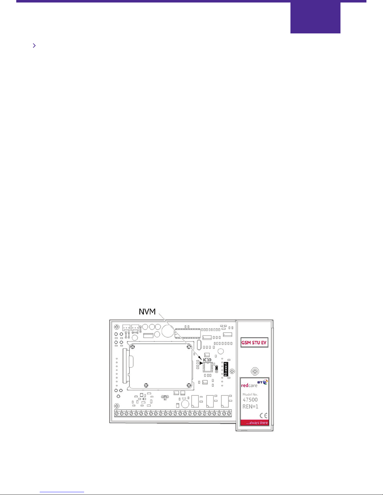
Suitable replacement NVMs for use with the GSM STU EV as IC10, are Microchip 93LC46B-I/PG OR 93LC46C-I/PG.
The NVM can be programmed using a Scantronic 7200 NVM programmer (version 1.2 or 1.3 software) or a Scantronic
7300 NVM programmer (version 1.3 software).
The NVM can be re-programmed after careful removal using an IC extractor. If the unit has already been commissioned,
see the note on page 3. The GSM STU EV and alarm system must be totally powered down (switch off mains power and
disconnect the battery) before fitting or removing the NVM.
Note the orientation of the device shown below and make sure it is fitted the correct way around.
Power on the GSM STU EV. The yellow STU status LED will fast flash indicating that the new NVM has been detected.
Remove the Mode link (LK2) from its neutral position and place it in the security position as shown.
Page 21
Page 23
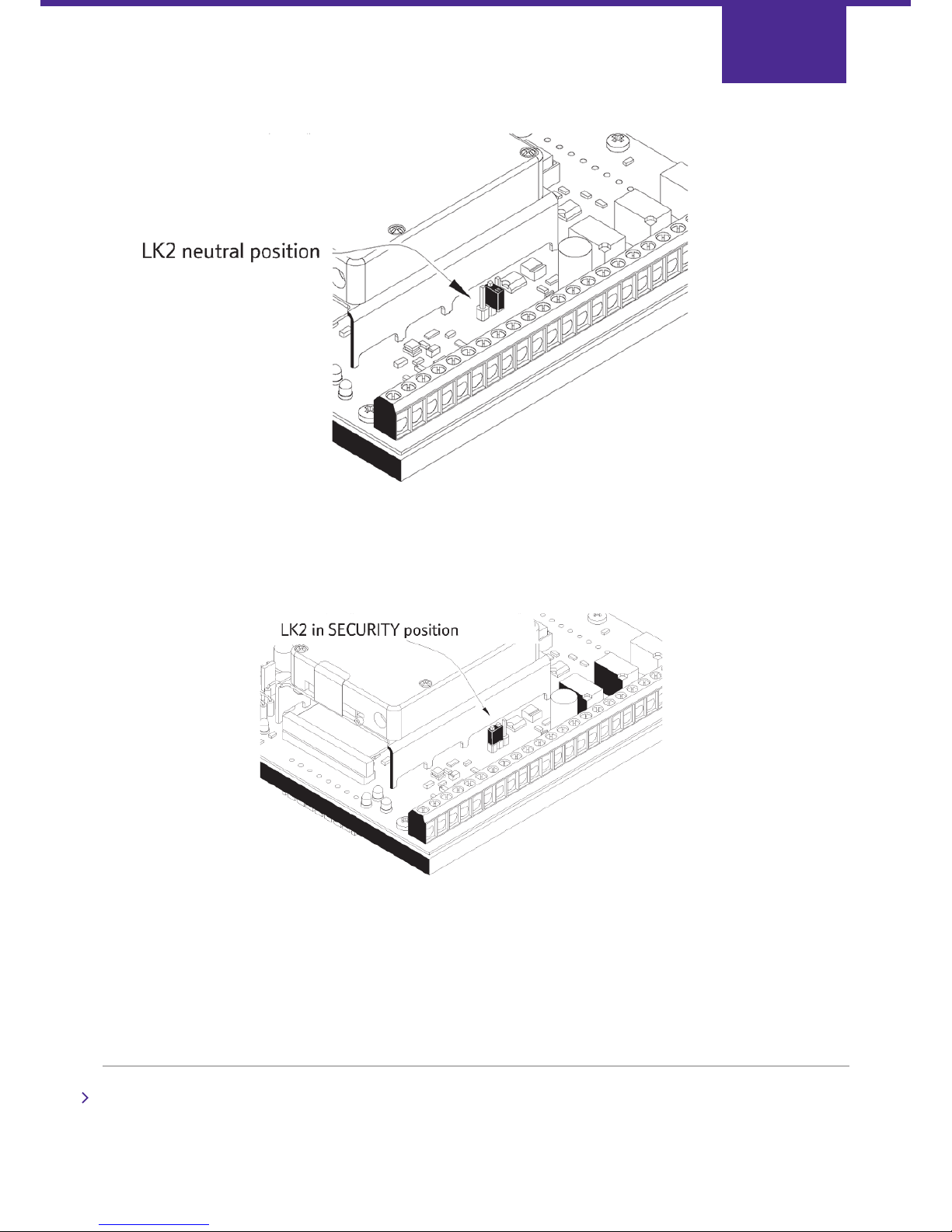
Leave LK2 in this position for three seconds. During this time the GSM STU EV stores the "NVM present" setting in its
EEPROM so that it can re-start correctly should a complete power fail occur in the future.
Remove the security link and store it in the "Neutral" position on LK2.
Remove power from the GSM STU EV completely.
Remote Programming
The EEPROM or NVM, if fitted, can be re-programmed remotely by the ARC. Only the relay states can be adjusted unless a
technician is on-site to set the GSM STU EV into Security Mode using LK2. Contact BT redcare for more information.
Page 22
Page 24
Pin Alarm Polarity
The pin alarm channels respond to the voltage level at the terminal block inputs (stand-alone mode) or the pins of SK1
and SK2 (plug-in mode). The appropriate terminal block inputs and plug-in connector socket pins are tracked together in
parallel on the circuit board. Each channel can be programmed to be "Positive Applied" or "Positive Removed". This polarity
is set to a default state in the EEPROM (see page 21). It can also be set in the NVM, or the GSM STU EV can
"learn" the polarity as detailed below.
Learning Procedure
Ensure that all the used channels are connected and set to be in their non alarm states.
Note: All channels will be enabled by the learning procedure.
If the tamper pin "T" is to be used, the learnt polarity in "LEARN" mode may be wrong if the alarm panel door is open.
Similarly, if a pin is designated an "Opening/Closing" channel, the learnt polarity in "LEARN" mode will be reversed.
For stand-alone applications (NOT PLUG-IN), these problems can be overcome by hard wiring the terminal block pins "4"
and "T" to 12 V or 0 V as required during the "LEARN" process. (Any connections to the alarm panel on these pins must
first be removed.)
If the learning procedure cannot be used to program the desired polarities, a plug-in NVM must be used.
If the unit has already been commissioned, decommission and power off the alarm system as detailed on page 3.
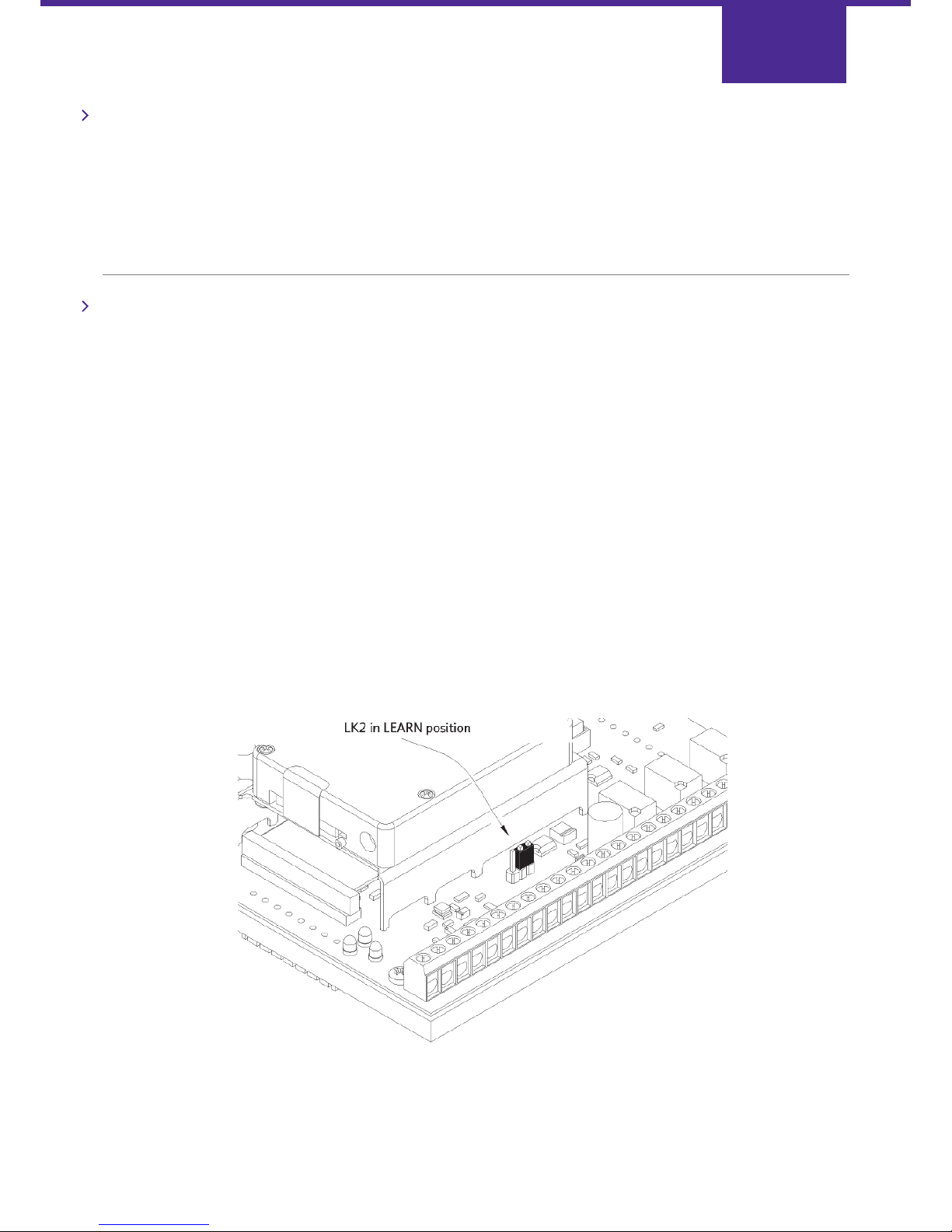
Power on the GSM STU EV and place the mode link at LK2 into the Security position (see page 22). Leave the link in this
position for two seconds and then remove it and place it across the adjacent pins into the "Learn" position as shown.
After five seconds, remove the link and return it to the "neutral" position.
The GSM STU EV will now learn the polarity of each alarm channel and store this data in its NVM (if fitted) and in its
EEPROM, overwriting any polarity data already there. During this process, the yellow STU Status LED4 will flash very
quickly for a few seconds and then the STU will reset.
Page 23
Page 25
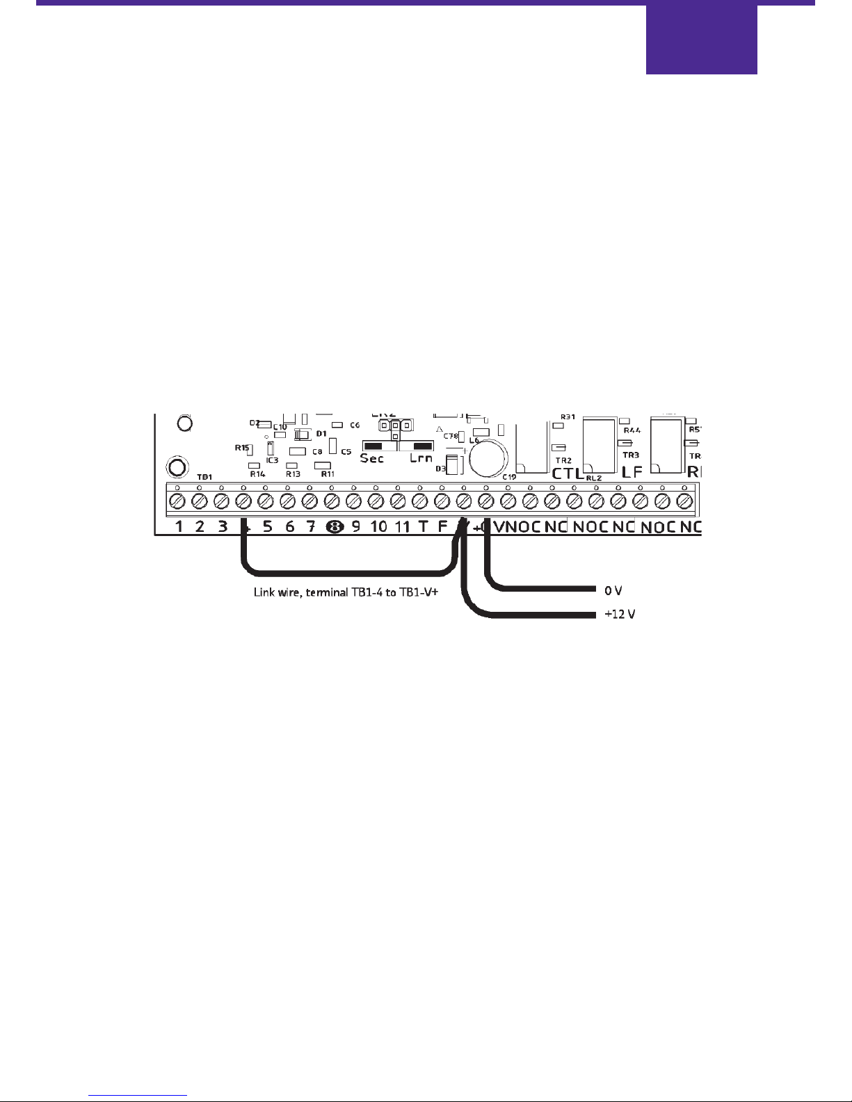
If the learning procedure is required again, the whole procedure must be performed starting from "Learning Procedure"
on page 23.
In some cases, particularly GSM STU EV plug-in installations, it may be difficult to perform the Learn Procedure because
not all the alarm pins can be set to their normal state for the GSM STU EV to learn. This problem may be resolved by
using the Learn Procedure with the GSM STU EV disconnected from the panel as
described below:
1. Completely disconnect the GSM STU EV from the alarm panel.
2. Connect all pins that are to be "positive removed" to the V+ output, and leave all other alarm pins unconnected.
3. Apply 12 V dc power to the GSM STU EV.
4. Perform the Learn Procedure.
5. Disconnect the power and remove all connections to the alarm pins.
6. Install the GSM STU EV.
For example, the GSM STU EV below is set up to learn the configuration of alarm pin 4 as "Positive Removed" and all
other alarm pins "Positive Applied".
Page 24
Page 26

Programming The NVM
Page 27
Programming The NVM
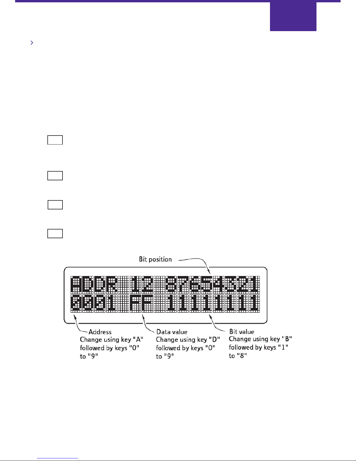
The following procedure should be followed when programming NVMs for the GSM STU EV using a Scantronic 7200 or
7300 NVM programmer.
Apply power to the programmer (12V DC or 12V AC.) and set the on/off switch to position "0". Insert the NVM in the
socket marked ‘COPY NVM’. Ensure that the dot on the NVM lines up with the white dot on the programmer.
Set the on/off switch to position ‘1’ and wait for the programmer to display its version information, for example:
V1.3
# 001957
Press and the screen displays:
MASTER NONE
COPY 9314/C46
Press and the screen displays:
SIMPLE 8400,8440,9056 PROGRAMMING
Press once, or twice for 7300, until the screen displays:
READ/MODIFY COPY SOCKET DATA
Press and the screen displays:
Page 26
YES
YES
YES
No
Page 28
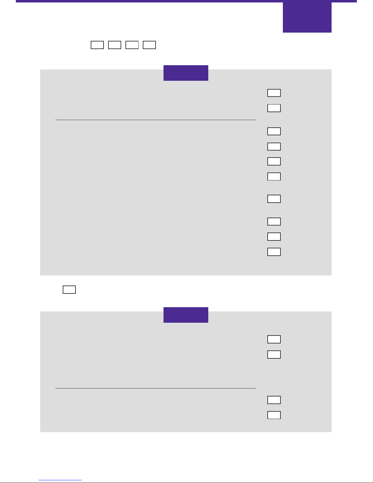
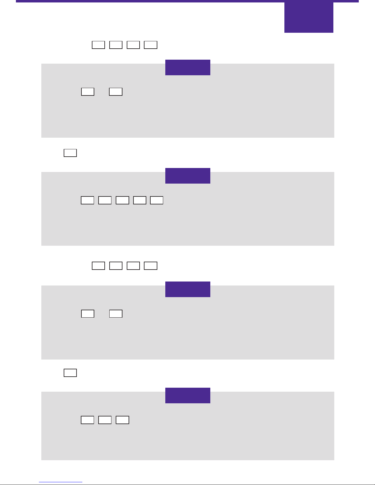
Press in sequence: The address display changes to:
Page 27
Press…. to advance the address display to:
A 3
YES
2 D
0 0 3 2
0 0 3 3
If the Control Relay is to be energised on power up press …………………………….…..
If the Control Relay is to be not energised on power up press …............................….
If the Line Fault Relay is to be energised on fault, press …………………………………..
If it is to be not energised, press ……...............................................................……….…
Line Fault Relay not energised and output signal on SK2 pin 15 inverted, press……..
Line Fault Relay energised and output signal On SK2 pin 15 inverted, press…………..
Line Fault Relay not energised and output signal
Comms Fail on SK1 pin 7 inverted, press………..............................................................
Line Fault Relay energised and output signal
Comms Fail on SK1 pin 7 inverted, press………..............................................................
Line Fault Relay not energised and both output signals inverted, press…………………
Line Fault Relay energised and both output signals inverted, press………………………
If the Telephone Line Type is PSTN press ….................................................................
If it is a private wire press ……………………....................................................................
(Different key presses may be required to overcome certain equipment
compatibility problems: see page 37.)
For normal Line Monitoring mode press …...............................................................….
For Earth Calling mode press ………….....................................................................……
1
0
or
1
0
or
or
or
or
2
3
or
4
5
or
or
6
7
0
1
or
1
2
or
Page 29
Page 28
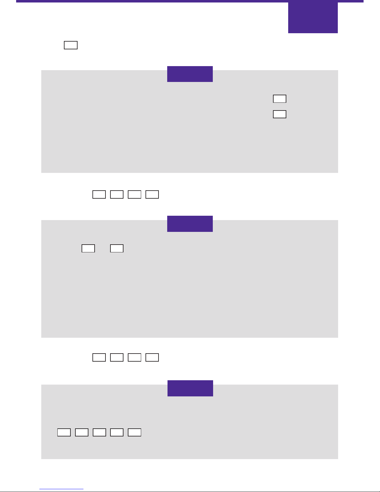
Press…. to advance the address display to:
YES
Press in sequence: The address display changes to:
A 3 5 B
Press in sequence: The address display changes to:
A 4 7 D
0 0 3 5
Use keys to to set the bits required for the options detailed:
00000000 Line fail asserted when both paths fail.
00000001 Line fail asserted when either path fails.
00000010 Line fail asserted when landline path fails.
00000011 Line fail operates in accordance with BSIA specification.
00000110 Line fail asserted when landline path fails and RPS relay operates when GSM path fails.
00001010 Line fail asserted when landline path fails and Control Relay operates when GSM path fails.
0 0 3 4
Press …………………………………………......................................................................…..
Press ………………………………………......................................................................……...
(This disables serial data, and enables GSM operation)
0
1
1 4
0 0 4 7
Key in the first two digits of the hard ID, press yes and key in the final two digits.
For example, a hard ID of 0567 would be entered:
To maintain the highest level of security, the hard ID should be unique for each STU.
0 5 YES 6 7
Page 30
Page 29
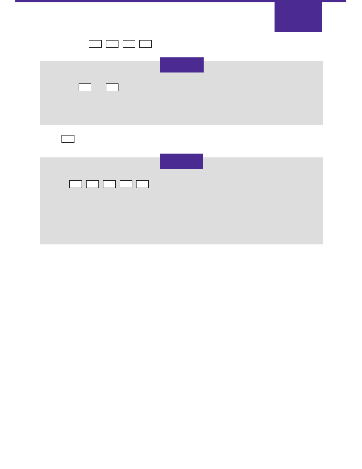
Press…. to advance the address display to:
YES
Press…. to advance the address display to:
YES
Press in sequence: The address display changes to:
A 6 0 B
Press in sequence: The address display changes to:
A 6 6 B
0 0 6 0
Use keys to to set the polarity of alarm pins 1 to 8.
Pressing the numbered key changes the setting of the polarity from 0 to 1, or 1 to 0. A state of 1 means
positive applied and a state of 0 means positive removed.
1 8
0 0 6 1
Use keys
to change the polarity of alarm pins 9, 10, 11, T and F respectively.
A state of 1 means positive applied and a state of 0 means positive removed.
1 2 3 4 5
0 0 6 7
Use the keys to designate alarm
pins 9, 10 and 11 respectively to be opening and closing channels. A state of 1 means that alarm pin is
an opening/closing channel a state of 0 means that it is not an opening/closing channel.
1 2 3
0 0 6 6
Use keys to to select the pins that are opening/closing
channels. A state of 1 means that the alarm pin is an opening/closing channel a
state of 0 means that it is not an opening/closing channel.
1 8
Page 31
Page 30
Press in sequence: The address display changes to:
A 7 0 B
Press…. to advance the address display to:
YES
0 0 7 1
Use keys to designate
whether alarm pins 9, 10, 11, T and F respectively are enabled. A state of 1 means the pin is enabled and
a state of 0 means the pin is disabled.
The NVM is now completely programmed. Set the power switch to 0, remove the programmed NVM and
insert it in the GSM STU EV at position IC10 (see page 21).
1 2 3 4 5
0 0 7 0
Use keys to to designate alarm pins that are enabled.
A state of 1 means the pin is enabled and a state of 0 means the pin is disabled.
1 8
Page 32

Status Indicators
Page 33
Status Indicators
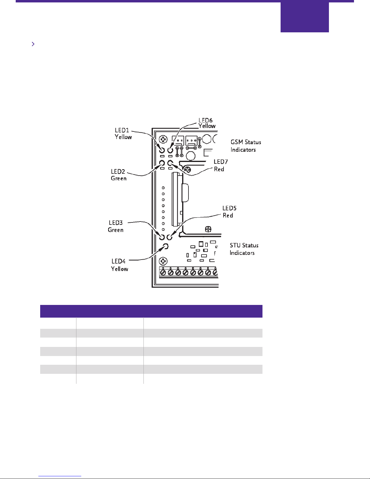
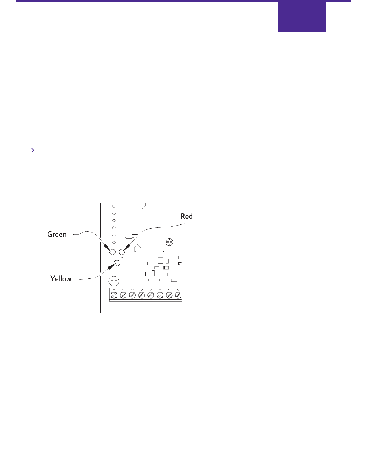
The status indicators are to be found in two distinct groups:
STU Status Indicators:
Three LEDs in the bottom
Left corner of the circuit board
Page 32
LED Indication Normal state
1 (yellow) GSM Signal Strength 1 On
6 (yellow) GSM Signal Strength 2 On
2 (green) GSM Transceiver OK Flashing every 2 s
7 (red) GSM Status Off
3 (green) STU Status 1 Intermittent flash
5 (red) STU Status 2 Off
4 (yellow) Warning Off
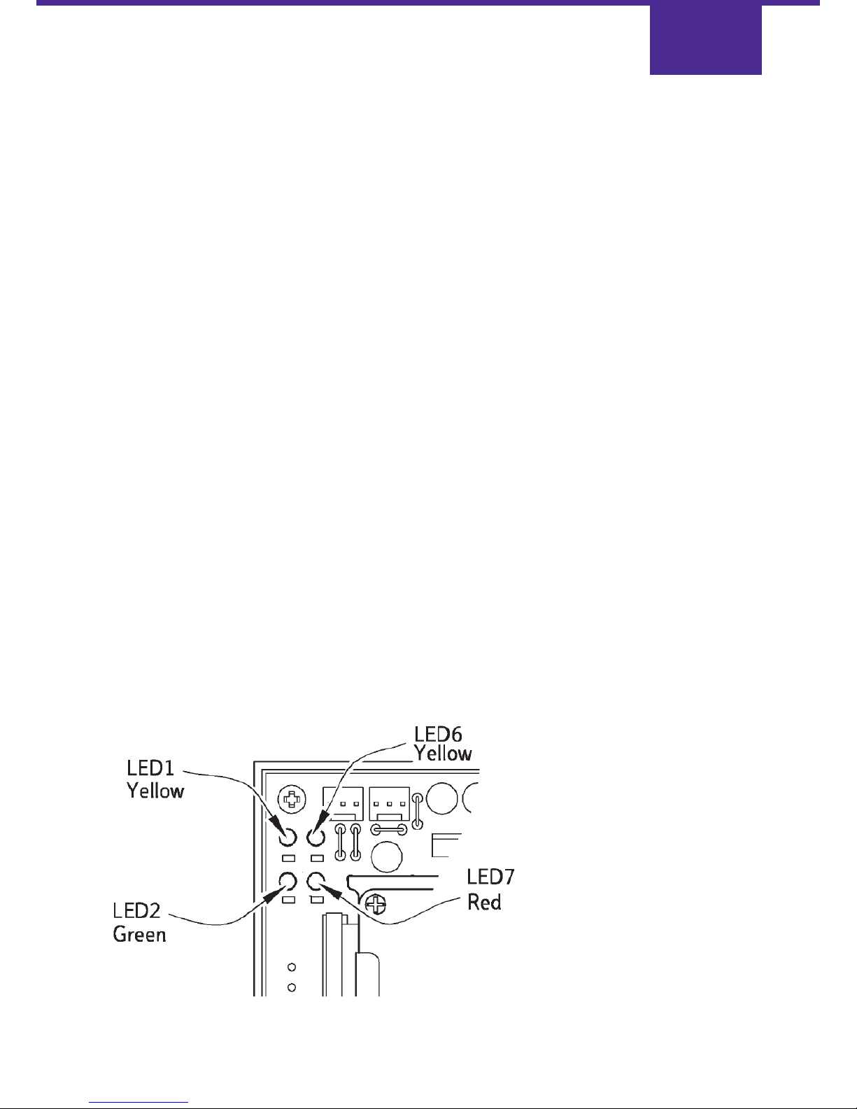
GSM Status Indicators:
Four LEDs in the top left
corner of the circuit board.
Page 34
Key to LED flash rates:
Slow
About 2½ s on, 2½ s off.
Medium
About 1¼ s on, 1¼ s off.
Fast
About ⅓ s on, ⅓ s off.
Flutter
About 12 flashes per second.
Intermittent
One or more flashes about ⅓ s on and then off for more than 2½ s.
STU Status LED Meanings
The STU status is indicated on the LEDs in priority order - highest first. Where a high priority condition exists, it is
indicated on the LED and suppresses the indication of lower priority conditions.
For example, if a battery low condition is present, battery low is indicated on the red LED regardless of the state of AC Fail.
Green flutter flash for ⅔ s:
Transmitting or receiving alarm data over landline.
Green fast flash:
Landline has failed (GSM signalling starts)
Green intermittent flash:
Landline is up and GSM STU EV commissioned.
Green slow flash:
The GSM STU EV has not been commissioned by the ARC.
Green permanently off:
GSM STU EV is not powered.
Page 33
Page 35
Red permanently off:
Normal
Red fast flash:
Battery power is low. Battery low is indicated on the LED as soon as it is detected. The battery low alarm is only
transmitted after a delay.
Red slow flash:
Mains power supply failed. AC Fail is indicated on the LED as soon as it is detected. The AC Fail alarm is only transmitted
after ten to twenty minutes. AC Fail alarm input (pin F) must be enabled in the NVM and the signal from the power
supply wired to the terminal marked "F" on terminal block TB1.
Red flutter flash:
The GSM STU EV has detected an NVM configuration error.
Yellow off:
Normal
Yellow flutter flash:
STU is learning pin alarm polarities.
Yellow fast flash:
The NVM chip has been changed (or installed for the first time).
Yellow medium flash:
The GSM STU EV is in Security Mode. While the GSM STU EV is in Security Mode, it will indicate Line Fault OK on both the
plug-in connector (SK2 pin 15) output and on the Line Fault relay. Security Mode will be cancelled if the GSM STU EV is
reset (i.e. power cycled), or if it is upped on the landline, or after 20 minutes. If necessary, Security Mode can be
re-enabled after upping to indicate Line Fault OK for another 20 minutes. This feature solves the problem of "Line
Fault" being displayed by certain alarm panels before the GSM STU EV is commissioned.
Yellow intermittent flash:
GSM STU EV has one or more alarms or openings/closings present.
Alarms counted include alarm pins 1 to 11 only. The LED flashes once for each unacknowledged alarm on pins 1 to 11
and is then off for a few seconds. A pin 8 alarm will be triggered by a GSM failure. The alarm count does not include the
mains fail alarm
GSM LED Meanings:
Page 34
Page 36

Yellow:
These two LEDs indicate the GSM radio signal strength. The signal strength is adequate when both are illuminated.
If they do not light when the unit is in operation the signal strength is too low and the GSM STU EV will send a PIN 8
alarm over the PSTN.
If only LED1 is lit, signal strength is low and may be improved by fitting an extension antenna or re-siting the unit.
Yellow flutter flash:
GSM message received.
Green permanently on or permanently off:
GSM unit failed.
Green flashing every 2 s:
GSM unit working.
Red off:
GSM unit enabled (normal)
Red flutter flash:
The GSM unit has detected a fault with the SIM card in the GSM module.
Red slow flash:
Not commissioned.
Red medium flash:
Not initialised.
Red fast flash:
GSM network problem.
Red permanently on:
GSM module failed.
Page 35
Page 37

Note 1: The GSM STU EV should not be commissioned if a data device is busy using the telephone line.
Note 2: If an MCD is fitted it will disconnect the telephone or data device connected through it during commissioning.
Apply power to the alarm panel and the GSM STU EV and observe the STU Status indicators. The green STU Status LED
will slow flash (on for 2.5 seconds approx. and off for 2.5 seconds approx.).
Similarly, the GSM Status LEDs should be observed. When power is applied the GSM Status red LED should fast flash.
This indicates that the GSM unit is being initialised which will take one to two minutes. When the initialisation sequence is
complete, at least one of the two GSM Status yellow LEDs should illuminate and the GSM Status red LED will then slow
flash. The GSM STU EV is now ready to be commissioned.
During the commissioning procedure, the STU is "upped" on the landline and the GSM signalling path is enabled.
The GSM enabling sequence is started simultaneously to the landline upping procedure, but takes longer. Call the ARC,
preferably using the same line as the GSM STU EV, and ask them to commission the system ("Up the STU").
During this process the GSM status LEDs will flutter flash when any of the seven commissioning messages are transmitted
or received. When the GSM signalling path is fully enabled the GSM Status red LED will go out completely.
The green STU Status LED will give a short flutter each time a landline message, heard as a "chirp", is sent or received.
When the ARC confirms that the system is commissioned the green STU Status LED should flash every 5 seconds.
The yellow STU Status LED may either be off, or produce short flashes every 10 seconds. The short flashes indicate the
number of alarms triggered.
If, during the commissioning procedure, power to the GSM STU EV is interrupted, even momentarily, the above procedure
will have to be repeated.
Testing the System
Once the GSM STU EV has been commissioned, all of the used alarm inputs and relay outputs should be tested. To test
the alarm inputs you must be in contact with the ARC.
Each alarm should be tested in the following manner:
a) Trigger the alarm (the yellow STU Status LED4 should give one quick flash every 10 seconds signifying one
alarm has been triggered).
b) Ask the ARC to confirm that it has received the alarm message.
c) Ask the ARC to acknowledge the alarm.
d) Remove the alarm trigger (the yellow STU Status LED4 should stop flashing).
e) Ask the ARC to confirm that it has received the reset message.
f) Ask the ARC to acknowledge the reset.
If personal attack buttons form part of the system they must be tested as above.
If used, the Control Output should be tested as follows:
a) Ask the ARC to turn on the Control Output.
b) Confirm that Control Output is activated (e.g. Remote Reset).
c) Ask the ARC to turn off the Control Output.
d) Confirm that the Control Output is deactivated.
Page 36
System Commissioning
Page 38
If used, the RPS output should be tested as follows:
a) Trigger the alarm which has been designated as the opening/closing channel.
b) Confirm that the RPS warning device is activated and ask the ARC to confirm that it has received the opening message.
c) Ask the ARC to acknowledge the opening.
d) Confirm that the RPS warning device is de-activated.
The GSM backup system should be tested as follows:
a) Disconnect the GSM STU EV from the telephone line.
b) Confirm that the STU status green LED3 changes to fast flash after 30 to 90s.
c) Trigger an alarm and confirm that the ARC receives the alarm.
d) Reconnect the telephone line.
The Line Fault output should be tested as follows:
e) Disconnect the GSM STU EV from the telephone line.
f) Confirm that the Line Fault relay activates.
g) Replace the telephone line connection and ensure that the relay deactivates.
h) Carefully disconnect the antenna cable from the GSM module.
i) Confirm that the Line Fault relay activates within 210 seconds.
j) Reconnect the antenna and verify that the Line Fault relay is deactivated.
Note: The Line Fault relay test may not be 100% reliable as there may be enough signal to enable GSM communications
even without the antenna attached. (Observe the signal strength LEDs).
When all of the above tests have been successfully completed, all the alarm triggers should be removed and the Alarm
Receiving Centre asked to acknowledge all of the unacknowledged alarms. The GSM STU EV red LED5 should be off and
the green LED3 should produce a short flash every 5 seconds.
This signifies that the GSM STU EV is commissioned and there are no outstanding alarms.
Affix the redcare gsm sticker to the outside of the box containing the GSM STU EV: this will indicate that the GSM
device is active inside.
Warranty
The warranty covers defects in materials and workmanship. The warranty is invalidated by misuse or neglect by the
customer and defects caused by improper installation or operating practices. Damage such as that caused by lightning
or inadequate return packaging will also void the warranty. In no event shall BT redcare be liable for any
consequential damage.
Repairs
Faulty GSM STU EVs must be returned to BT redcare for repair.
All non-warranty repairs are charged at a standard fixed price plus a shipping charge and VAT.
Page 37
Page 39

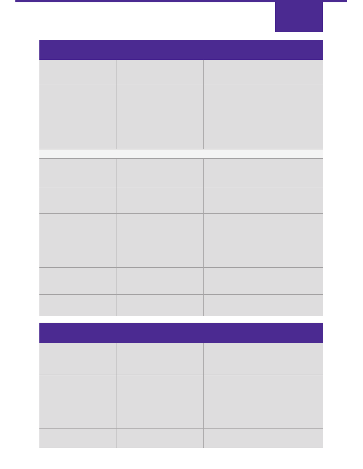
This section describes typical problems that may arise, the symptoms, possible causes and solutions.
If you have problems that you cannot resolve after consulting this section, please contact redcare Technical Helpline
Freephone: 0800 671 240
Chirps
The redcare system utilises an existing telephone line to provide a secure communications link between the alarm system
at the protected premises and the ARC.
To facilitate this, two modes of communication are employed: a continuous inaudible low-tone, normally present all the
time, and an audible ‘chirp’, used to transmit alarm messages and check for the presence of the STU.
These ‘chirps’ will not normally be heard, but they can occasionally occur as the telephone handset is lifted. This ‘chirp’
should be heard only once. If ‘chirps’ are heard regularly during conversation, please contact BT redcare for advice.
Substitution
BT redcare maintain a database of the unique CPE numbers matched to the associated PSTN telephone number and the
mobile phone number of the GSM unit. For this reason the SIM card in the GSM unit cannot be changed or used in
any other installation. If a GSM STU EV is suspected of being faulty, it is not possible to substitute the unit for a different
one without the help of BT redcare.
Equipment Compatibility Issues
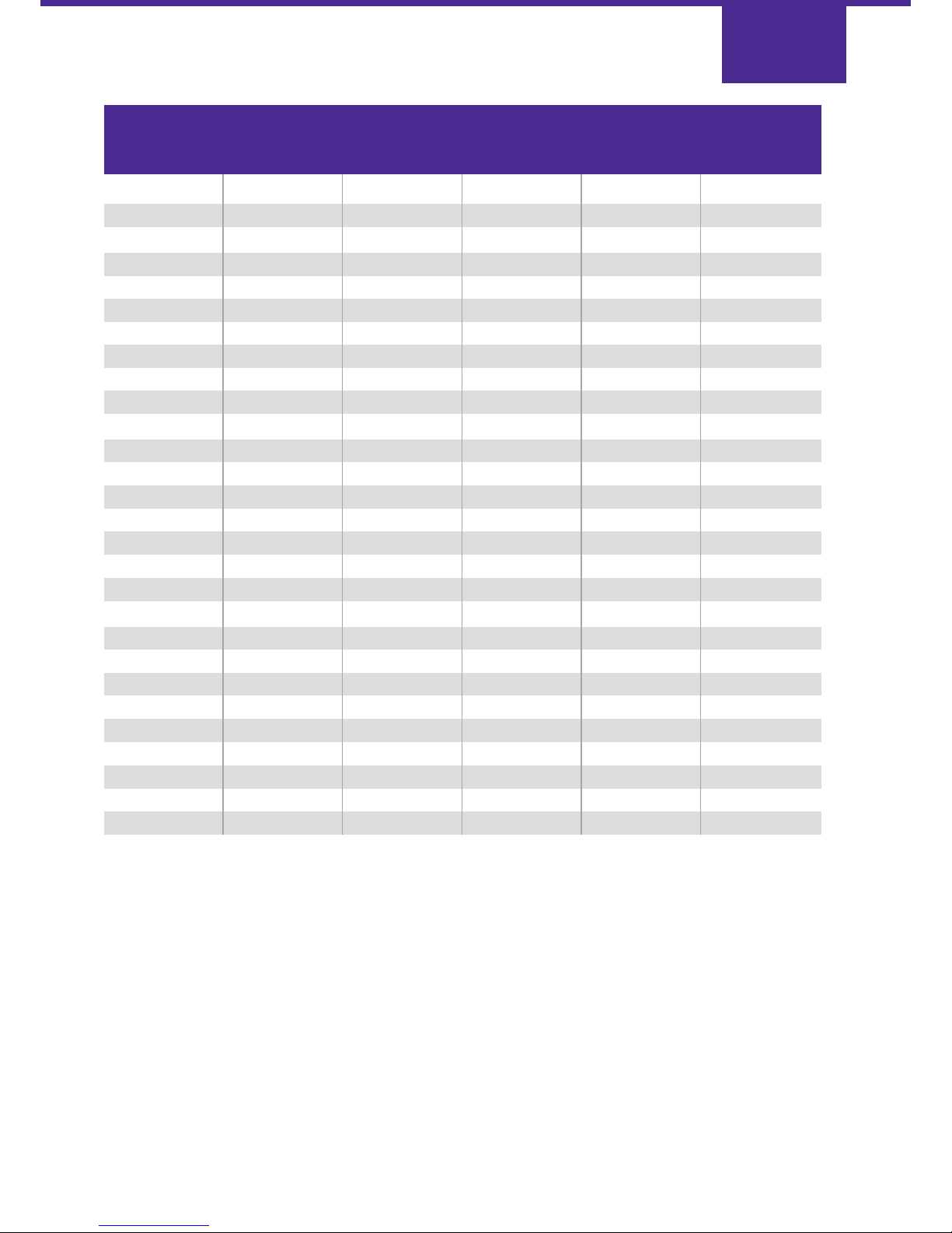
Certain compatibility issues with specific equipment can be overcome by changing the low-tone signalling level output
from the STU. Only where advised by BT redcare, the low-tone attenuation setting can be changed by reprogramming
the NVM. The NVM address concerned is number 33 which also contains the line monitoring mode setting. The options
available are shown on page 39.
Page 38
Troubleshooting
Page 40
Page 39
PSTN No 0 dB 0 dB 21 00100001
PSTN No 0 dB -3 dB 01 00000001
PSTN No 0 dB -6 dB 31 00110001
PSTN No 0 dB -9 dB 41 01000001
PSTN No -3 dB -3 dB 51 01010001
PSTN No -3 dB -6 dB 61 01100001
PSTN No -3 dB -9 dB 71 01110001
PSTN No -6 dB -6 dB 81 10000001
PSTN No -6 dB -9 dB 91 10010001
PSTN No -9 dB -9 dB A1 10100001
PSTN Yes 0 dB 0 dB 22 00100010
PSTN Yes 0 dB -3 dB 02 00000010
PSTN Yes 0 dB -6 dB 32 00110010
PSTN Yes 0 dB -9 dB 42 01000010
PSTN Yes -3 dB -3 dB 52 01010010
PSTN Yes -3 dB -6 dB 62 01100010
PSTN Yes -3 dB -9 dB 72 01110010
PSTN Yes -6 dB -6 dB 82 10000010
PSTN Yes -6 dB -9 dB 92 10010010
PSTN Yes -9 dB -9 dB A2 10100010
PW n/a 0 dB 0 dB 11 00010001
PW n/a 0 dB 0 dB 12 00010010
PW n/a -3 dB -3 dB D1 11010001
PW n/a -3 dB -3 dB D2 11010010
PW n/a -6 dB -6 dB E1 11100001
PW n/a -6 dB -6 dB E2 11100010
PW n/a -9 dB -9 dB F1 11110001
PW n/a -9 dB -9 dB F2 1 11110010
Line
Type
Earth
Calling
Line
On
Hook
Atten.
Off
Hook
Atten.
Data Value
at
Address 33
Bit Value
Page 41

Page 40
Symptom Possible Causes Possible Solution
Problems indicated on the STU Status LEDs
Yellow STU Status LED4 a) NVM not fitted. a), b), c) Insert correctly programmed NVM.
Fast flash. b) NVM unprogrammed.
c) NVM wrong way around. d) Refit NVM.
d) NVM leg bent under. e) Power down, insert the NVM and re-apply
e) The NVM has been removed power to the GSM STU EV. Ask the ARC to
from the STU. commission the STU again.
f) Configure the STU to use the plug-in
f) NVM fitted for the first time. NVM (see page 24).
When an alarm is triggered a) An alarm previously a) Ask the ARC to acknowledge any
the number of outstanding transmitted on the same channel outstanding alarms.
alarms does NOT increase. has not been acknowledged
The yellow STU Status LED4 by the ARC. b) Re-program the NVM.
is off or the number of b) The NVM has been incorrectly
flashes of the yellow LED programmed and the alarm channel
stays the same. The green has been disabled by mistake.
STU Status LED3
intermittent flash.
The Yellow STU Status LED4 Each yellow LED flash represents an a) Check/correct the alarm input wiring.
flashes up to eleven times outstanding alarm. b) i) Re-configure alarm settings.
after every other flash of the a) Alarm input/s may be ii) Re-program the NVM
green STU Status LED3. incorrectly wired. iii) Use the "LEARN" polarity procedure.
b) Alarm information may be
programmed incorrectly in the NVM.
Page 42

Page 41
Symptom Possible Causes Possible Solution
Red STU Status Power supply and/or Check the operation of the power
LED5 fast flash. battery voltage to the supply. Check that the back up
GSM STU EV is too low. battery is charged.
Red STU Status NVM program error. GSM disabled in NVM, in this case, it
LED5 flutter flash. may still be possible to up the GSM STU EV
on the landline only.
Re-program the NVM.
Red STU Status AC fail alarm in NVM i) Re-program the NVM.
LED5 slow flash, or EEPROM wrong polarity. ii) Use the "LEARN" polarity procedure.
but mains is present
on power supply.
ARC cannot a) GSM STU EV is not a), b), c) Seek assistance from the ARC.
commission the enabled by BT Red.
GSM STU EV, b) Wrong phone line
and the phone line being used
is otherwise OK. c) Wrong GSM STU EV
Green STU Status commissioned by
LED3 slow flash. the ARC.
ARC is reporting There has been a Ask the ARC to commission the STU again.
NO RESPONSE and momentary power
chirps can be heard failure in the control panel.
on the phone line.
Green STU Status
LED3 slow flash.
ARC is reporting There is a failure of Report the failure to your local BT fault
NO RESPONSE and the phone line. repair service. Phone 151 for residential
chirps CANNOT be customers. Phone 154 for business and
heard on the RedDIRECT customers.
phone line.
(Green STU Status
LED3 fast flash.)
Problems indicated on the GSM Status LEDs
Red GSM Status The SIM card may be Contact redcare Helpdesk for assistance.
LED7 fluttering. damaged, wrong or missing.
Page 43
Page 42
Symptom Possible Causes Possible Solution
Regular ‘chirps’ are heard The NVM has been programmed Re-program the NVM for ‘PSTN mode’.
(every 2½ to 3 minutes) for Private Wire mode and the STU
whenever the telephone is connected to a normal
is in use. phone line (PSTN).
Calls cannot be made from a) LK1 fitted when STU is a) Remove LK1.
the GSM STU EV connected to the PSTN. b) Check and correct the wiring.
phone line. b) Incorrect phone line wiring to c) Seek assistance from the ARC.
the STU. d) Report the fault to your local BT fault
c) Faulty wiring at the redcare block repair service.
terminal.
d) Faulty phone line.
The ARC is reporting the This is an internal alarm generated by The STU has detected a fault in its
receipt of a channel 15 alarm. the STU to indicate a self test failure. internal circuitry. Replace the STU.
Symptom Possible Causes Possible Solution
Green GSM The GSM unit has Power cycle the GSM STU EV and try to
Status LED2 failed to initialise. commission it again.
permanently on.
No GSM signal a) The antenna may be a) i) Check antenna connection.
strength LEDs disconnected or the ii) Use extension antenna.
are illuminated. signal is being blocked. iii) Remove local obstruction from
around antenna.
b) Contact redcare Helpdesk for assistance.
b) The SIM card may not
be enabled onto the
GSM network.
Problems NOT indicated by the LEDs
The alarm panel is in The line fault output has been Re-program the NVM.
a permanent local line programmed to the
fault condition. wrong polarity.
Regular ‘chirps’ are heard PABX or telephone Report make and model details to
(every 2 minutes) when compatibility problems redcare Helpdesk and ask for advice.
ever the telephone is in use
The ARC is reporting the a) This is an internal alarm generated Re-program the NVM.
receipt of a channel 12 alarm by the STU to indicate a
but tamper pin is not active. tamper condition.
b) The NVM has been removed from
a commissioned STU.
c) Tamper pin set to the wrong
polarity in the NVM
The ARC is reporting the This is an internal alarm Possible mains failure or faulty battery.
receipt of a channel 14 alarm. generated by the STU to indicate
a battery low condition.
No activity on the The power is off. Check for 12V dc at TB1 V+
GSM STU EV, no LEDs on. with respect to TB1 0V
Page 44

The symbol shown here and on the product, means that the product is classed as Electrical or
Electronic Equipment and should not be disposed of with other household or commercial waste at
the end of its working life.
The Waste Electrical and Electronic Equipment (WEEE) Directive (2002/96/EC) has been put in place
to recycle products using the best available recovery and recycling techniques to minimise the impact
on the environment, treat any hazardous substances and avoid the increasing landfill.
Product disposal instructions for residential users:
When you have no further use for it, please dispose of the product as per your local authority’s recycling processes.
For more information please contact your local authority or retailer where the product was purchased.
Product disposal instructions for business users:
Business users should return the product to the freepost address below:
Freepost RLXS-ETYY-ELCU
Rebound Electronics UK Ltd.
Basingstoke
Hants
RG24 8FL
Only return the product sub assembly (not the complete alarm panel) to BT redcare for recycling.
Page 43
Disposal
Page 45

To find out more about Redcare:
call us free on 0800 800 628
*
or email [email protected]
* Calls are free to this number from BT landlines and BT payphones.
However, they are not free to call from mobile phones
the costs will vary between service providers.
© British Telecommunications 2017.
Registered office: 81 Newgate Street, London, EC1A 7AJ
Registered in England no. 1800000
PHME 73282
Never compromise
 Loading...