

Page 1
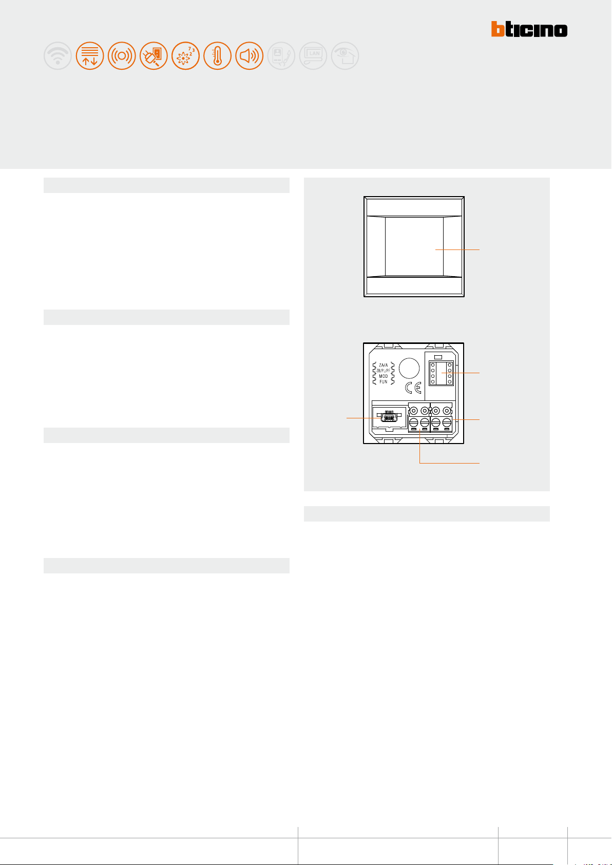
Description
Local Display is a device that gives the possibility of 4 home automation functions by
means of simple and intuitive icons displayed on a 1.2” OLED display with touch screen
technology.
It can be used to manage the temperature control, sound system, energy management,
and scenario functions.
The back of Local Display has a USB socket, which can be used to connect the device
to a PC, to update the configuration, the set of characters, and the icon, as well as the
firmware.
HD4891 - HC4891 - HS4891
L4891 - N4891 - NT4891Local display
1
Technical data
- Power supply from BUS: 18 – 27 Vdc
- Stand-by Absorption: max 10 mA @ 27 Vdc
max 15 mA @ 18 Vdc
- Operating absorption: max 50 mA @ 27 Vdc
max 70 mA @ 18 Vdc
- Operating temperature: 5 – 35 °C
- Size: 2 ush mounted modules
Conguration
Local Display may be configured in two ways:
- physical conguration, by connecting the congurators to the appropriate sockets.
This mode gives the possibility of configuring with basic parameters only 1
function to manage, among the ones listed below. For the configuration of the
advanced parameters use the TiLocalDisplay software.
- from the PC, using the dedicated TiLocalDisplay software. This mode gives the
possibility of configuring all the parameters, for the management of 1 to 4
functions listed below.
Funzioni gestibili
- Scenario control
- Temperature control with external probe 3457
- Temperature control with probe HD/HC/HS4693, L4693, N4693, NT4693.
- Sound system
- Consumption display
- Load management
- Advances scenarios (with MH200N programmer installed in the system), to be
configured using the software only
Front view
5
Rear view
Legend
1. OLED technology Touch Screen
2. Congurator socket
3. BUS clamp
4. Clamp for the connection of the external temperature probe
5. USB connector
2
3
4
Technical sheets - Automation MY HOME
BT00517-a-UK
1
Page 2
HD4891 - HC4891 - HS4891
L4891 - N4891 - NT4891
Installation
Local Display is installed using a traditional procedure, using a box, support, and
AXOLUTE or LIVINGLIGHT cover plate; the device is not tted with a temperature probe.
Therefore, it will not be necessary to comply with the probe installation requirements.
The recommended installation height is 150 - 160 cm.
Local Display physical conguration
- Scenario control mode - FUN = 1
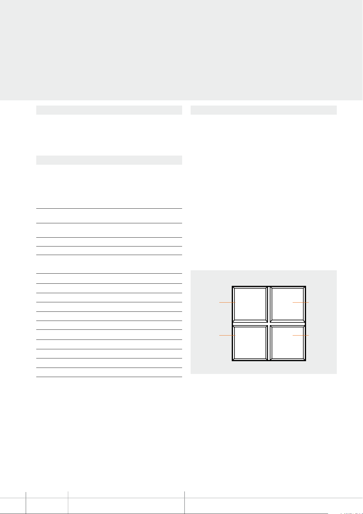
Thanks to this mode, it will be possible to manage and change 4 dierent associated
scenarios of the F420 scenario module, and activate them by pressing one of the 4 icons
shown on the display.
A Room 0 – 9, room of the scenario module
item
PL Light point 1 – 9, light point of the scenario
module item F420
MOD Mode 1 – 4, scenario number (*)
FUN Function 1
(*) Correspondence among the 4 icons and the numbers of the scenarios that can be
saved in the F420 module
Configurator MOD Icon 1 Icon 2
1 Scenario 1 Scenario 2
2 Scenario 5 Scenario 6
3 Scenario 9 Scenario 10
4 Scenario 13 Scenario 14
Main functions that can be set using the Tilocal Display software
Main possible functions using the software:
- selection of the operating mode to set for the device, temperature control, scenarios,
sound system, load management, consumption display.
- conguration of the settings of the probe and of its parameters;
- denition of the type of temperature central unit;
- parameters for the measurement of energy production, or consumption costs;
- conguration of the general device parameters;
- icon style denition.
scenario 1
scenario 2
1 2
Configurator MOD Icon 3 Icon 4
1 Scenario 3 Scenario 4
2 Scenario 7 Scenario 8
3 Scenario 11 Scenario 12
4 Scenario 15 Scenario 16
Scenario programmer
In order to program, change or cancel a scenario, it is necessary to enable the
programming mode of the Module item F420 so that the status LED is green (press the
BT00517-a-UK
lock/unlock key on the Scenario Module for at least 0.5 seconds); continue with the
following operations:
1) press one of the four control keys the scenario should be associated to for 3
seconds. The screen shows the name and icon of the selected scenario and
the programming bar, to indicate that the learning procedure has started
If the device does not receive any input for 30 minutes from the start of the learning
procedure, programming will automatically be interrupted;
2) set the scenario using the corresponding controls for the various Automation,
Temperature control, Sound system, etc. functions;
3) conrm the scenario by quickly pressing the display
4) to change or create new scenarios to be linked to the other keys, repeat the procedure
starting from point 1.
To call a set scenario just press its pushbutton on the control quickly.
MY HOME Technical sheets - Automation
2
scenario 3
scenario 4
3 4
NOTE: Once the operations have been performed lock the programming, pressing the
lock/unlock pushbutton, of the senario module, for at least 0.5 seconds, so that the
corresponding LED becomes red.
To delete a scenario, proceed as follows:
1) the scenario module must be enabled for programming.
2)
press the pushbutton of the scenario you want to cancel for at least 7 seconds
The display will conrm that the scenario has been deleted and return to the main
screen.
To erase the entire memory keep the DEL pushbutton on the Scenario module
pressed for 10 seconds, the yellow “reset scenarios” LED ashes quickly.
;
Page 3
HD4891 - HC4891 - HS4891
L4891 - N4891 - NT4891
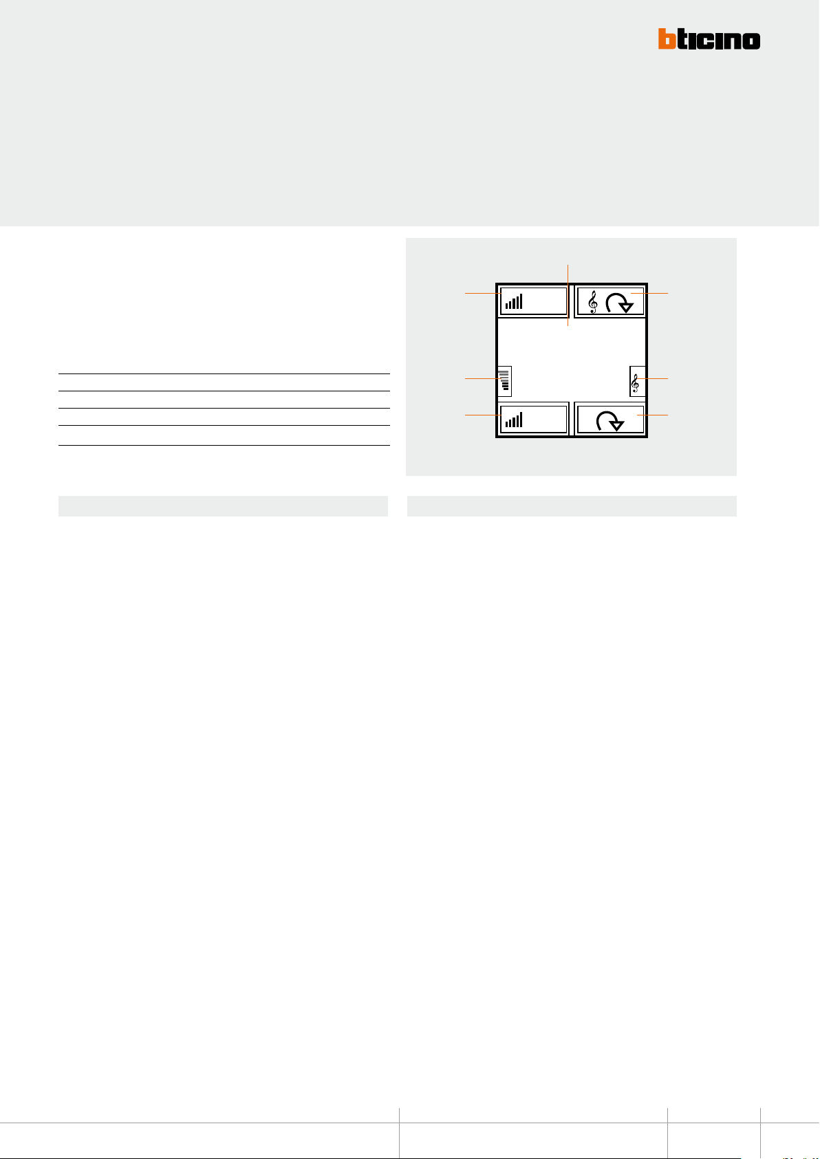
– Sound system control mode - FUN = 2
With this mode, for the associated amplier the user can control the switching ON or OFF,
the volume, the cycling through the sources, and their management (where allowed).
Information on the currently active source is also displayed.
In this mode the parameters that can be congured are the local address of the display (which
must coincide with the A/Pf address, and the M1 mode of the associated amplier), and the
name of the sources that can be controlled.
A Room 0 – 9, amplifier room
PF Loudspeaker 1 – 9, Amplifier loudspeaker
MOD Mode 0 – 8, Source switching ON (*)
FUN Function 2
NOTA (*): If M=0, source 1 is switched on without first switching OFF the sources
(follow-me mode).
Functions
A quick pressure of keys 5 and 7 will respectively switch ON and OFF the associated
amplier. If the associated amplier is on, an extended pressure of keys 5 and 7 may be
used to adjust the volume, the intensity of which will be displayed by means of an icon
5. A short pressure of keys 2 and 4, will respectively cycle through the sources installed
in the system, and launch a control for the currently activ
amplier is o and no source is on, the screen
will not show any information. Press key 4 for 3 seconds to congure the alarm clock (see
the user manual for details).
e source. If the associated
1
7
ON
RDS
6
5
Legend
1. Indication of the amplier status or radio frequency
2. Cycling of sources (radio/aux)
3. Active source indication
4. Change radio station
5. Associated amplier OFF and volume decrease
6. Volume level indication
7. Associated amplier ON and volume increase
106.70
OFF
2
2
3
4
Technical sheets - Automation MY HOME
BT00517-a-UK
3
Page 4
HD4891 - HC4891 - HS4891
L4891 - N4891 - NT4891
- Temperature control probe mode with external probe FUN = 3
Warning: the physical conguration can only be performed if the system includes a
99-zone temperature central unit.
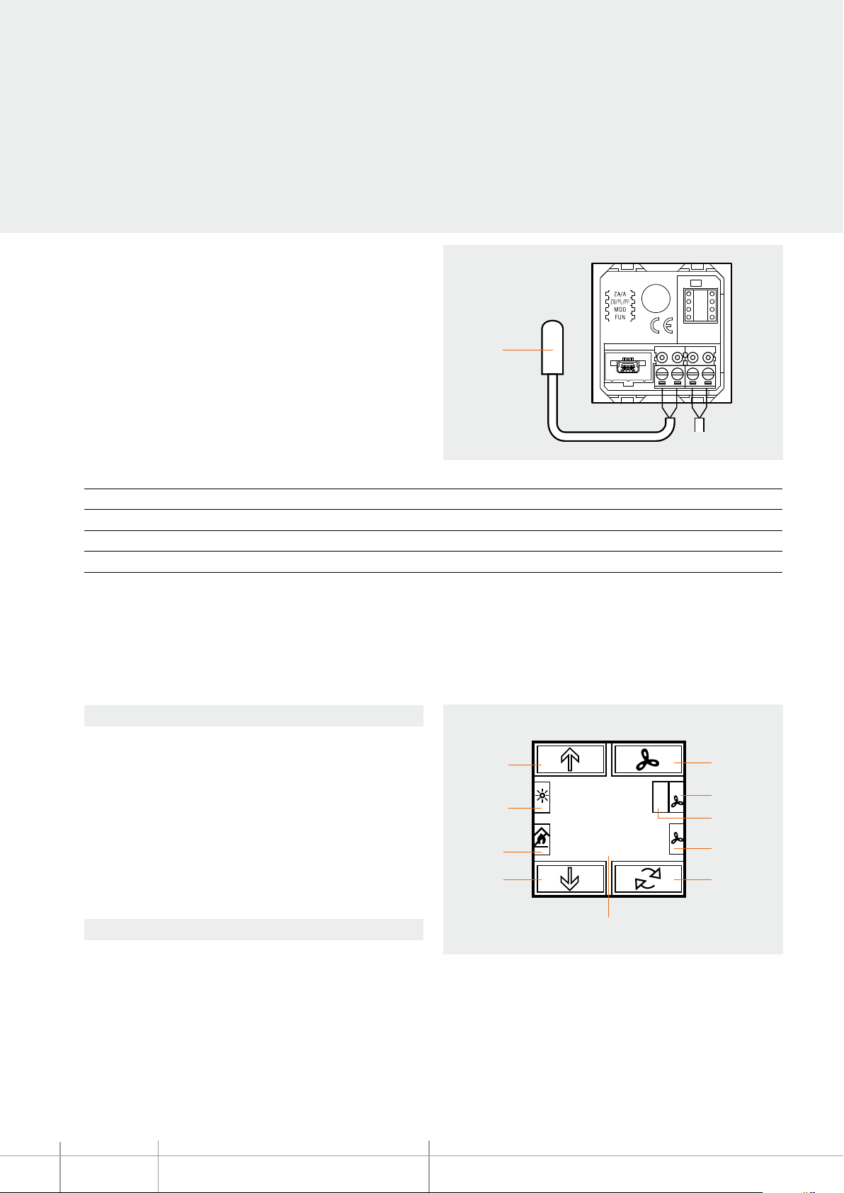
An external temperature probe, item 3457, with the following characteristics, can be
connected on the back of Local Display:
- 10 KΩ at 25 °C BETA 3435
- max. length of the connection 10 metres
Local Display shows the temperature value measured by the external probe, the set
temperature value, and the local selector adjustment. The operations that may be
performed by user are:
- variation of the temperature set using the local selector,
- FAN-COIL speed management,
- operating mode management.
ZA Zone address 0 – 9, Local Display address
ZB Zone address 1 – 9, Local Display address
MOD Mode 0 – 8, Slave probe number
FUN Function 3
temperature
probe
BUS - SCS
For simple systems, where each zone controls at most one heating actuator and one air
conditioning actuator, both of the ON/OFF type, and on a system with only one pump
per function, the con guration of the system can be performed by simply connecting
the con gurators that identify the address of the device and, in case of probe, indicate
the number of slaves present.
1. Set temperature
2. Fan-Coil adjustment
3. Fan-Coil speed indication
4. Temperature variation indication
5. Fan-Coil operation indication
6. Change operating mode
7. Measured temperature
8. Decrease temperature
9. Operating mode indication
10. System status indication
11. Increase the temperature
BT00517-a-UK
A short pressure of keys 8 and 11 can be used to locally change the temperature by
+/-3 °C, in relation to the settings received from the central unit. A short pressure of
key 6 can be used to select the mode of operation, cycling through the OFF, antifreeze/
thermal protection, and automatic statuses respectively. Each mode of operation is
identi ed by a di erent icon. A short pressure of key 2 will force the speed the fan-coils,
cycling through speed 1, 2, 3 or automatic.
Legend
Functions
For more complex systems, the probe can memorize the actuators to activate, and the
pumps to control on the BUS. The programming operation must be completed directly
from the central unit. The central unit can also be used for the calibration of the probe.
During the system setting stage, it will be necessary to specify the actuators used for
the heating system, and those used for the air conditioning system, as they operate in
a complementary way.
11
10
9
8
25.5°
26.3°
7
+
2
2
2
3
4
5
6
MY HOME Technical sheets - Automation
4
Page 5
HD4891 - HC4891 - HS4891
L4891 - N4891 - NT4891
- Temperature control probe mode with item HC4693,
HS4693, L4693, N4693, NT4693 probe - FUN = 4
Warning: physical conguration can only be used if a 99-zone temperature control
central unit is installed in the system
This mode is dierent from the previous one in the fact that the external probe is not
connected to Local Display. Being unable to autonomously establish the temperature,
it must be associated to at least one probe, items HC4693, HS4693, L4693, N4693, or
NT4693. The user is shown the temperature value measured by the associated probes,
the set temperature value, and the adjustment of the local selector.
ZA Zone address 0 – 9, probe address
ZB Zone address 1 – 9, probe address
MOD Mode 1 – 8, Slave probe number
FUN Function 4
The possible operations for the user are the adjustment of the set temperature using
the local selector, and the change of status of the probe. In this mode, the parameters
that can be congured are the local display address (which must coincide with the
ZA/ZB address of the associated probe), the type of control of the pump, the type of
mode, and the number of slave probes.
For simple systems, where each zone controls at most one heating actuator and one air
conditioning actuator, both of the ON/OFF type, and on a system with only one pump
per function, the con guration of the system can be performed by simply connecting
the con gurators that identify the address of the device and, in case of probe, indicate
the number of slaves present.
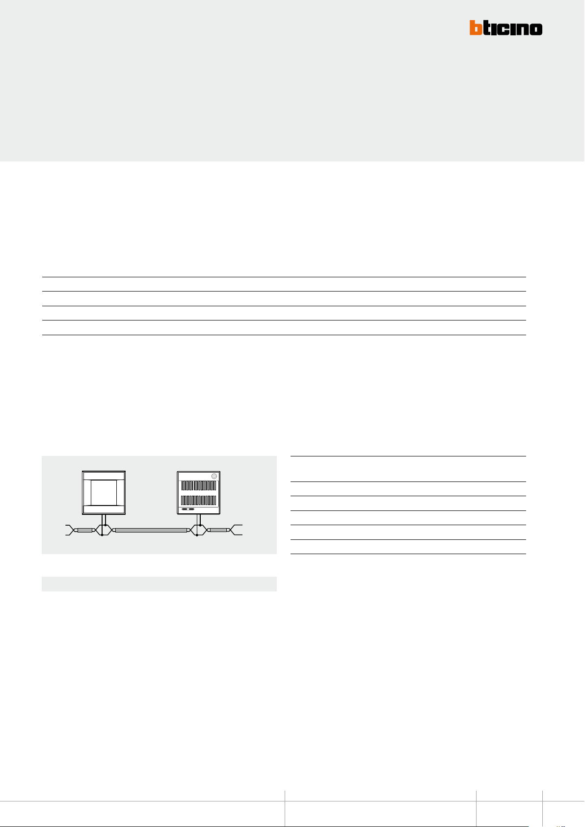
Example of conguration of a zone (address 47) with Local Display and probe
item HC4693, HS4693, L4693, N4693, NT4693
Local
display
Functions
A short pressure of keys 8 and 11 can be used to locally change the temperature by
+/-3°C, in relation to the settings received from the central unit. A short pressure of
key 6 can be used to select the mode of operation, cycling through the OFF, antifreeze/
thermal protection, and automatic statuses respectively.
Slave
probe
For more complex systems, the probe can memorize the actuators to activate, and the
pumps to control on the BUS. The programming operation must be completed directly
from the central unit. The central unit can also be used for the calibration of the probe.
During the system setting stage, it will be necessary to specify the actuators used for
the heating system, and those used for the air conditioning system, as they operate in
a complementary way.
Local Display
(HC/HS/L/N/NT4891)
Socket Congurator Socket Congurator
ZA 4 ZA 4
ZB 7 ZB 7
MOD 1 MOD SLA
FUN 4 SLA 1
Sonda Slave
(HC/HS/L/N/NT4693)
Each mode of operation is identied by a dierent icon. A short pressure of key 2 will
force the speed the fan-coils, cycling through speed 1, 2, 3 or automatic.
Technical sheets - Automation MY HOME
BT00517-a-UK
5
Page 6
HD4891 - HC4891 - HS4891
- Energy Management Mode – consumption display FUN=5
It is possible to display the consumptions and the production of several energies of the
system, with monitoring of up to a maximum of ten lines.
Warning: with physical conguration, only the consumptions of one line can be
displayed.
ZA Line address 0 – 9
ZB Line address 1 – 9
MOD Type 0 = ELECTRICITY
FUN Function 5
For each line, the consumptions and the instantaneous, daily, monthly, and annual
economic evaluation are displayed.
It will be possible to set two maximum consumption values, with the device emitting
visual and sound notications if these are exceeded. In this case, the displayed value will
be green when below both limits, yellow when one has been exceeded, and red when
both have been exceeded.
1 = WATER
2 = GAS
3 = DHW
4 = HEATING/COOLING
L4891 - N4891 - NT4891
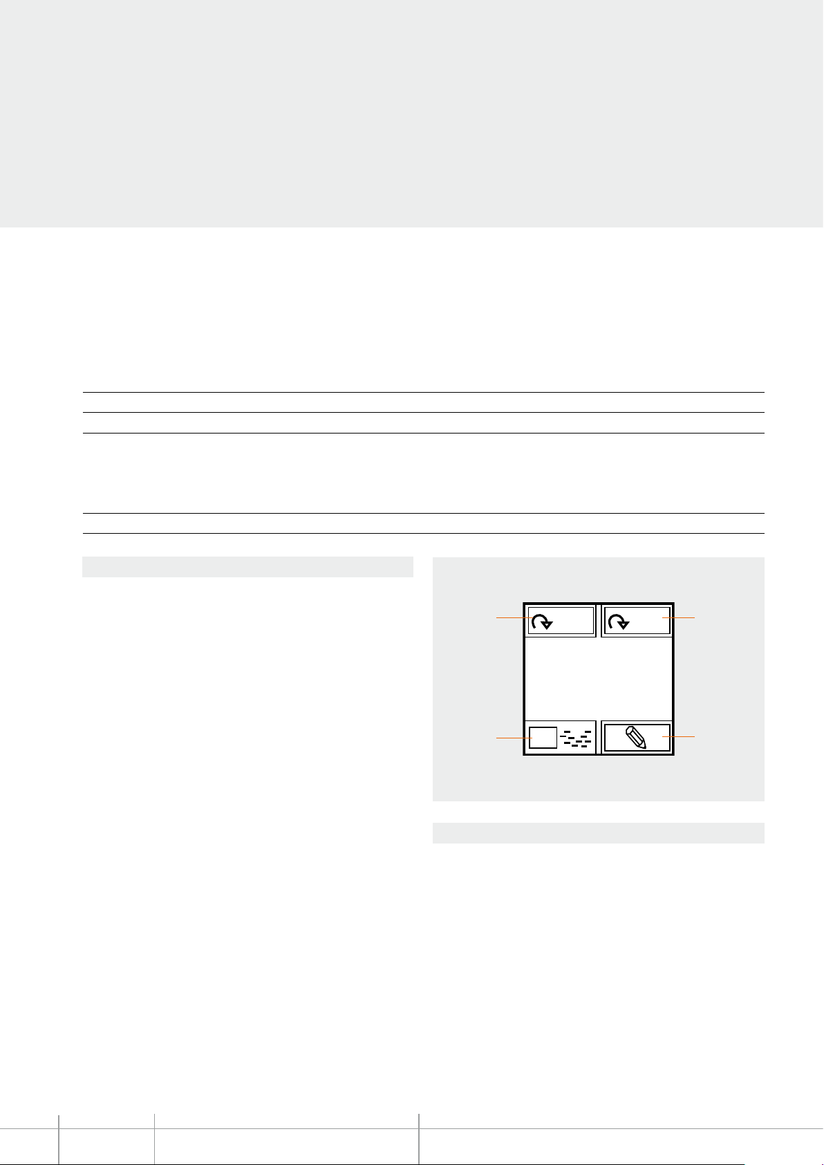
Once the device has been congured, it will be possible to scroll through the various
lines using icon 4. For each measurement interface, by pressing briey icon 3 it will then
be possible to display the consumptions or the economic evaluation.
Press and hold down icon 3 to access a submenu where it will be possible to change the
basic value of the economic evaluation.
Consumption and economic evaluations are themselves split into: instantaneous, daily
(D), monthly (M), annual (Y). It is possible to scroll through these settings using icon 1.
Press and release icon 2 to access a submenu that can be used to set the time, the date,
the threshold levels (if enabled), and the possibility of enabling or disabling the beep
emitted when the threshold is exceeded.
BT00517-a-UK
Functions
4
m
3
Kw
D/M/Y
Total
115.4
kwh
3
Legend
1. selection of display times
2. setting of the functions (time, date, max. power, etc.)
3. economic display of the consumptions
4. selection of the lines to display
$
1
D
2
MY HOME Technical sheets - Automation
6
Page 7
i
- LOAD MANAGEMENT mode
This mode, only available if Local Display is congured using the software, gives the
possibility of displaying loads, with their priority levels, and force their activation. The
device can manage up to 20 loads; if these are connected to actuators with current
sensor it will be possible to display other load information, like the instantaneous power
consumption.
When the central unit for load management intervenes on a load, the device (if enabled
during the conguration) noties the event with an indication on the display and an
audible notication.
HD4891 - HC4891 - HS4891
L4891 - N4891 - NT4891
4
ON
1
6
Oven
Functions
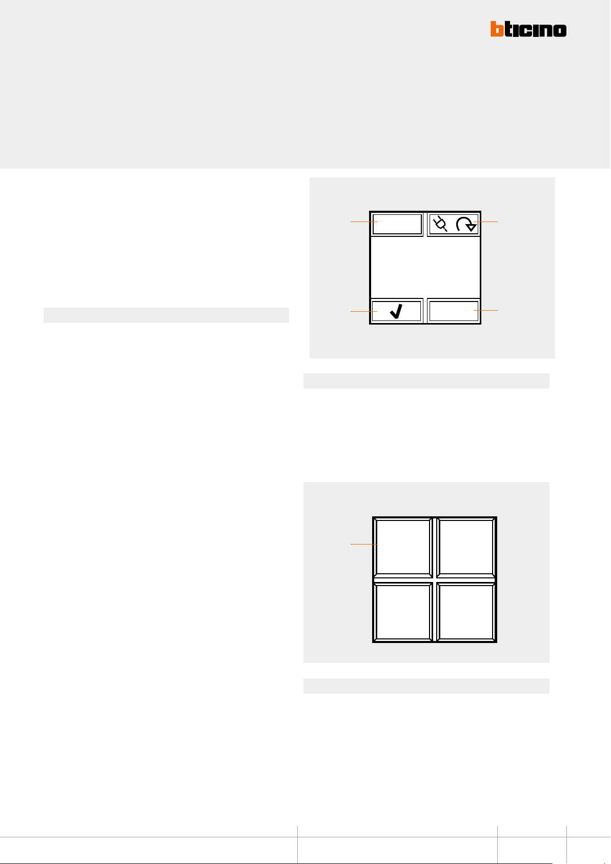
After the conguration of the device it will be possible to select the various loads using
icon 1.
Icon 4 is disabled until the moment the central unit disables the load; when this
happens, the icon becomes active, and can be selected to force the activation of the load.
In this condition, icon 3, used to intervene on the status of the load, is disabled.
However, if icon 4 is disabled, it will be possible to select icon 3 to pre-force the load,
and avoid disconnection in case of intervention of the central unit when consumptions
are exceeded.
If the loads are connected to actuators with current sensor, use icon 2 to access a
submenu that can be used to display the instantaneous power consumption, as well as
information form the line total consumption meters. While in this submenu, you can use
the RESET icon to reset the meters. Press key 2 for 3 seconds to access the menu used for
setting the time, the date, and the sound notication (beep).
- Advanced CEN SCENARIO mode
For systems with MH200N scenario programmers, Local Display can be used to enable 1
of the 4 scenarios displayed. This is done using the associated icons.
This function is only available if Local Display has been congured using the software.
3
Legend
1. selection of the load to control
2. display of consumption data and device setup
3. activation/deactivation of the load
4. forced activation of the load disconnected by the energy management central unit,
due to consumptions being exceeded.
1
2
1 2
3 4
Legend
1. scenario indication icon
Technical sheets - Automation MY HOME
BT00517-a-UK
7
 Loading...