

Page 1
1
322011
4
A (mm) B (mm) C (mm)
125 325 44,5
1
2
3
5
6
7
9
10
12
11
8
A C
B
D45 System
Description
Digital colour entrance panel
with addresses list
D45 System entrance panel with colour camera and backlighted alphanumeric keyboard
equipped with pushbutton to direct calls to the porter switchboard. Possibility to send
an alarm message to the switchboard when opening over two minutes of the associated
lock or when trying to remove the device. Setup parameters via device keyboard.
Configuration by device menu and keyboard or through the dedicated software
(supplied with the product). Residents can be called in 3 different ways :
- searching the name of the resident in the addresses list by using up & down arrow keys
- entering the resident surname by using the alphanumerical keyboard (same way as
for the mobile phone)
- direct call by typing the resident corresponding numerical code (you must know the
resident code).
Flush mounting installation with dedicated box - supplied with the product.
Related items
322012 Targa module
346250 Door lock relay
Technical data
Power supply: 30 Vdc
Stand by absorption: ≤ 25 mA @ 30 V
Max operating absorption: ≤ 245 mA@30 V
Camera sensor: 1/3”
Lens: F3.6 mm
Camera diagonal view angle: 85°
Camera distance up to clear picture: 16.4 cm
Camera resolution: 540 TV Lines (horizontal)
Camera minimum lux level visibility: 0.01 lux (compensation lamp OFF)
0 lux (compensation lamp ON)
Operating temperature: (-25) – (+55) °C
Protection index: IP54
Protection against mechanical impact: IK07
Dimensional data Legend
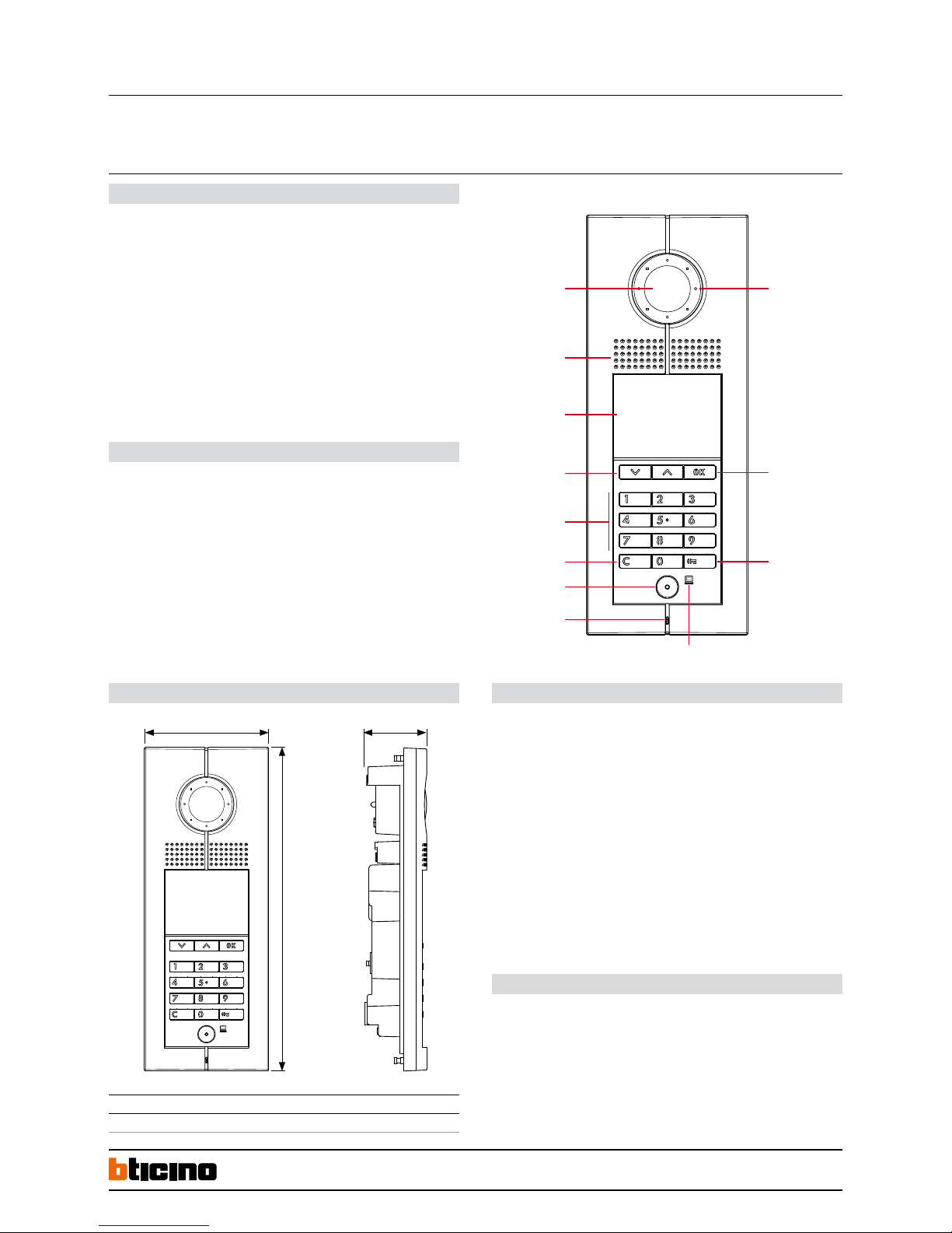
1. Compensation Lamp
2. Send call to the selected resident key
3. Door lock release key
4. External light sensor
5. Microphone
6. Direct call to the management center pushbutton
7. Delete & Return key
8. Alphanumerical pushbuttons
9. Navigation / search for the resident keys
10. Backlighted LCD display
11. Loudspeaker
12. Adjustable colour camera
Front view
BT00853-a-EN 03/09/2014
Page 2
2
322011
11
9
8
4
67
5
3
2
1
10
A (mm) B (mm) C (mm)
120 314 55
A C
B
Digital colour entrance panel
with addresses list
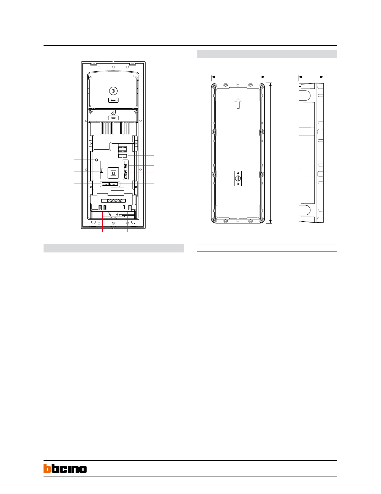
Rear view
Legend
1. NN RRRR: configurators housing
2. ISP: entrance panel software upgrade connector
3. SPK: loudspeaker volume adjust
4. MIC: microphone volume adjust
5. VIDEO-IN/GND/NC/+12V/LED : entrance panel camera and compensation Lamp
connector
6. RJ45 Targa module connection
7. RJ45 System BUS connection
8. 6 poles connector :
– +12V/GND power supply for access control module (Optional)
– UNLOCK signal output from access control module (Optional)
– DAS electronic lock status signal connector
– LOCK-/LOCK+ electrical door lock connection
9. SPK-OUT/GND/GND/SPK-OUT: entrance panel loudspeaker connections
10. (V-GAIN) video gain setting
11. Password RESET pushbutton
Flush mounting box - dimensional data
BT00853-a-EN 03/09/2014
Page 3
3
N N R R R R
322011Digital colour entrance panel
with addresses list
Configuration & Settings
BT00853-a-EN 03/09/2014
Entrance panel must be configured for the following parameters:
NN : Entrance panel number
RRRR : NOT USED
Two different device configuration ways available:
WAY 1 ) Configuration settings by device keyboard
WAY 2 ) Configuration by using SF2 Software and PC connection
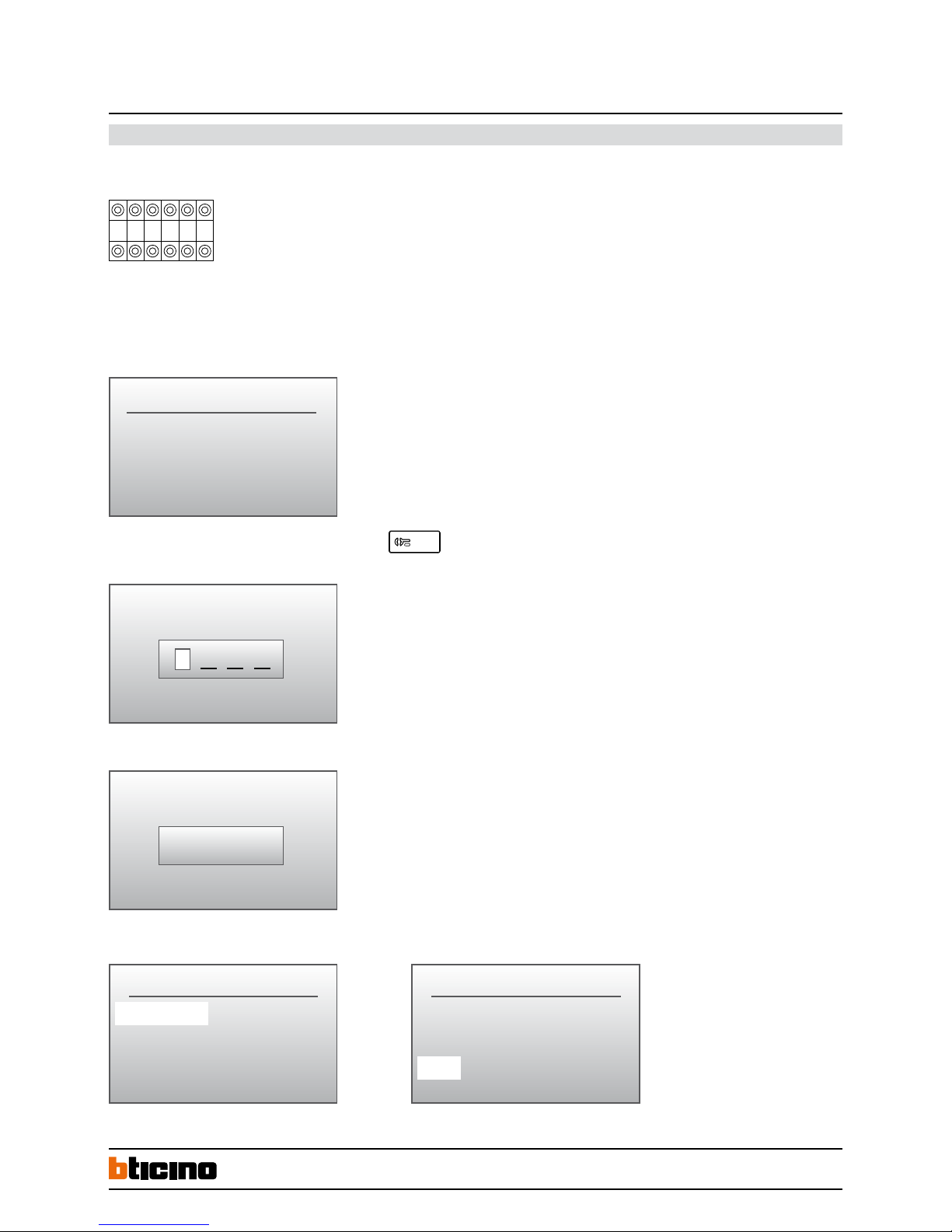
Configuration settings by device keyboard - WAY 1:
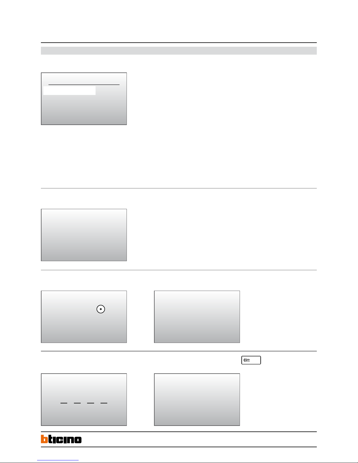
PASSWORD
Access to the configuration menù by press and hold the door lock key
for more than 10 seconds.
Enter the access code (DEFAULT 1 2 3 4)
PASSWORD
1 2 3 4
If the correct code has been entered, direct access to the configuration menù will be granted.
To exit from the configuration menù, or to return to the previous menù, select EXIT than press OK.
Welcome
CONFIGURATION
Language
Panel settings
Address book
CONFIGURATION
Phonic module settings
FW versions
EXIT
Page 4
4
322011Digital colour entrance panel
with addresses list
BT00853-a-EN 03/09/2014
Configuration & Settings
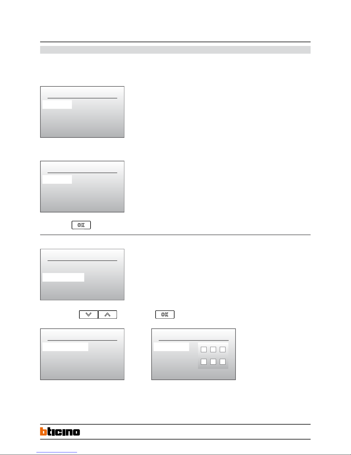
Changing the PASSWORD - if the password has been forgotten , it is possible to change it in this way : press the RESET pushbutton on the rear side of the device for about 6 seconds.
Password will be recovered to default (1 2 3 4).
Password setup
To change the access password, press OK than enter new password “6789”
Confirm by pressing
Entrance panel settings :
Select the menu function and confirm by pressing
Device settings submenu, allows you to set up the following parameters :
- display brightness adjustment
- display contrast adjustment
Press EXIT to return to the previous menu.
PASSWORD SETUP
Password 1234
EXIT
PASSWORD SETUP
Password 6789
EXIT
CONFIGURATION
Language
Panel settings
Address book
PANEL SETTINGS
Device settings
Password
Home page
DEVICE SETTINGS
Brightness
Contrast
EXIT
Page 5
5
Digital colour entrance panel
with addresses list
HOME PAGE
Template 1 line
Timeout 5 Sec
Text –––>
HOME PAGE TEXT
Line 1 –––>
Line 2 –––>
EXIT
Configuration & Settings
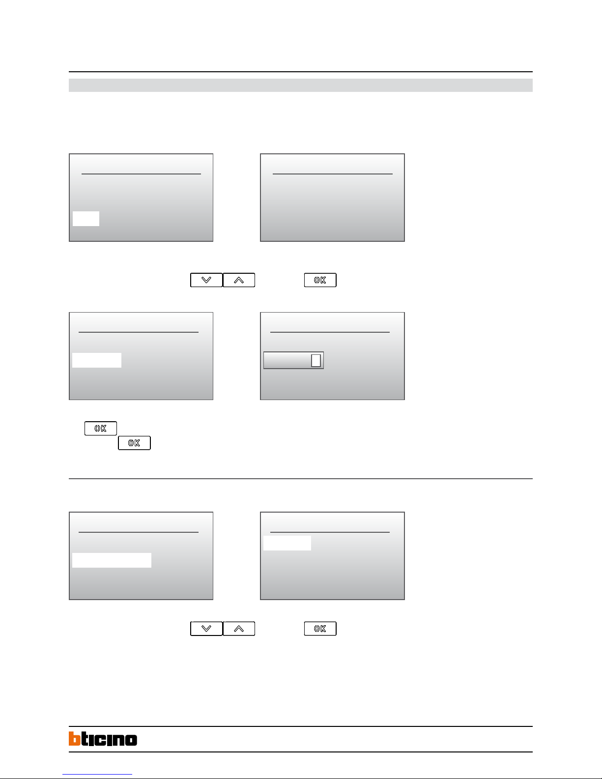
HOME PAGE - this menu function allows you to enter a customized welcome message or any other general message.
The message can fill a maximum of three text rows (15 characters max.) - Template.
Is possible to set the display time of the message on the screen (5, 10 or 15 seconds) - Timeout.
Select the line where to enter the text by using
and confirm with
Press to select the text field. Enter the message text by using the alphanumerical keyboard (in the same way as you write an SMS on your mobile phone).
Than confirm with
.
The message will continuously appear on the home page screen as for the time set in the Timeout menu.
Restore DEFAULT SETTINGS
Select the line where to enter the text by using
and confirm with
The settings of the entrance panel will be restored to the factory default settings.
NOTE : this operation does not delete the data contained in the resident address book.
HOME PAGE TEXT
Line 1
Welcome
EXIT
PANEL SETTINGS
Home page
Restore default
HOME PAGE TEXT
Line 1
MY TEXT
EXIT
HOME PAGE TEXT
Confirm
EXIT
322011
BT00853-a-EN 03/09/2014
Page 6
6
Configuration & Settings
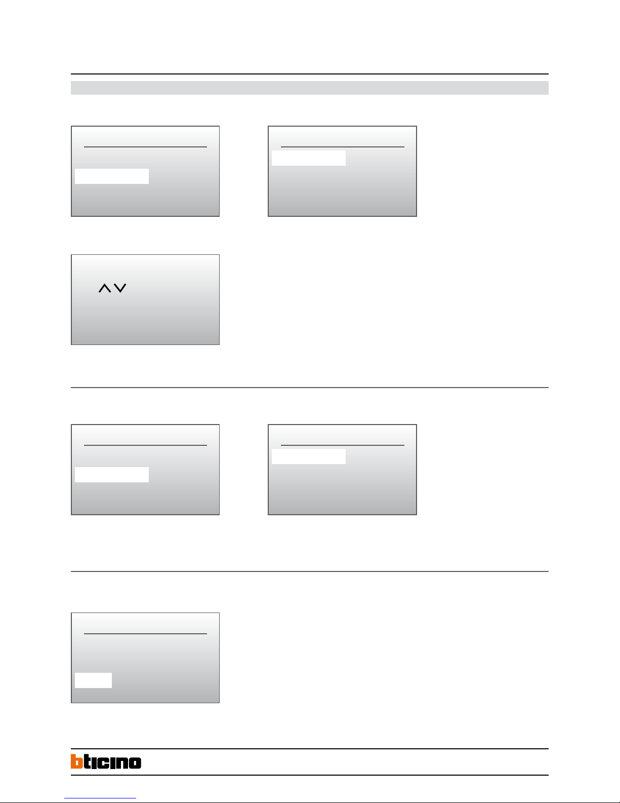
ADDRESS BOOK - This menu is used to to enter various residents data (including call codes and door lock release codes) as well as performing any other function described below :
List of names - this setting estabilish how the name of the residents will be displayed on the screen. ON = list enabled
To search the desired resident name, use the indicated keys or enter the surname by using the alphanumerical keypad.
Calling mode by type of code - Enter the type of code to be used to call the resident
Apart address = SCS address of the handset
Call mode = Numerical code assigned to the resident
Calling mode - recall - when this function is enabled, the entrance panel will automatically repeat the call every 25 seconds up to 2 times.
CONFIGURATION
Panel settings
Address book
Phonic module settings
CALLING MODE
List of names ON
Type of code –––>
Phonic module settings
CALLING MODE
List of names
Type of code –––>
Recall OFF
CONFIGURATION
List of names ON
Type of code –––>
Recall OFF
CODE TYPE
Apart address
*
Call code
EXIT
Select the name with
and press OK
322011Digital colour entrance panel
with addresses list
BT00853-a-EN 03/09/2014
Page 7
7
Configuration & Settings
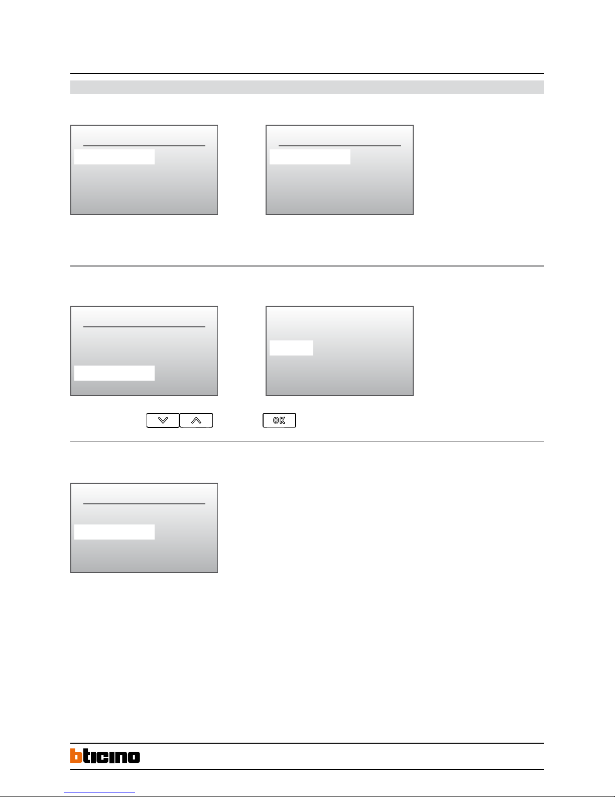
Contact setting - call codes can be set with a lenght from 1 to 8 digits. Door lock codes can be set with a lenght from 4 to 9 digits.
ADDRESS BOOK
Contact setting
New contact
Modify contact
ADDRESS BOOK
Contact setting
New contact
Modify contact
ADDRESS BOOK
Contact setting
New contact
Modify contact
ADDRESS BOOK
Call code digits 4
Lock code digits 5
EXIT
Aaaaaa
Call code digits : default 4 digits
Door lock release code digits : default 9 digits
Modify contact - this function gives you the possibility to change the selected contact.
Entering a new contact- this function gives you the possibility to enter new residents in the address book.
For each resident is possible to set the following parameters :
ID Number : identification progressive number automatically assigned by the device to each resident. This function gives you the possibility
to change this ID with a 4 digits number asigned by the installer.
Surname : surname of the resident.
Name : name of the resident.
Public : set on (YES), the name and the surname of the resident will appear on the display during the call selection.
set on (NO), the name and the surname are hidden. Resident call is possible by entering the call code.
Apart address : SCS address of the corresponding handset.
Call code : numerical c all code assigned to the resident.
Lock code : door lock release numerical code.
Select the contact to change
and confirm with
Digital colour entrance panel
with addresses list
322011
BT00853-a-EN 03/09/2014
Page 8
8
Configuration & Settings
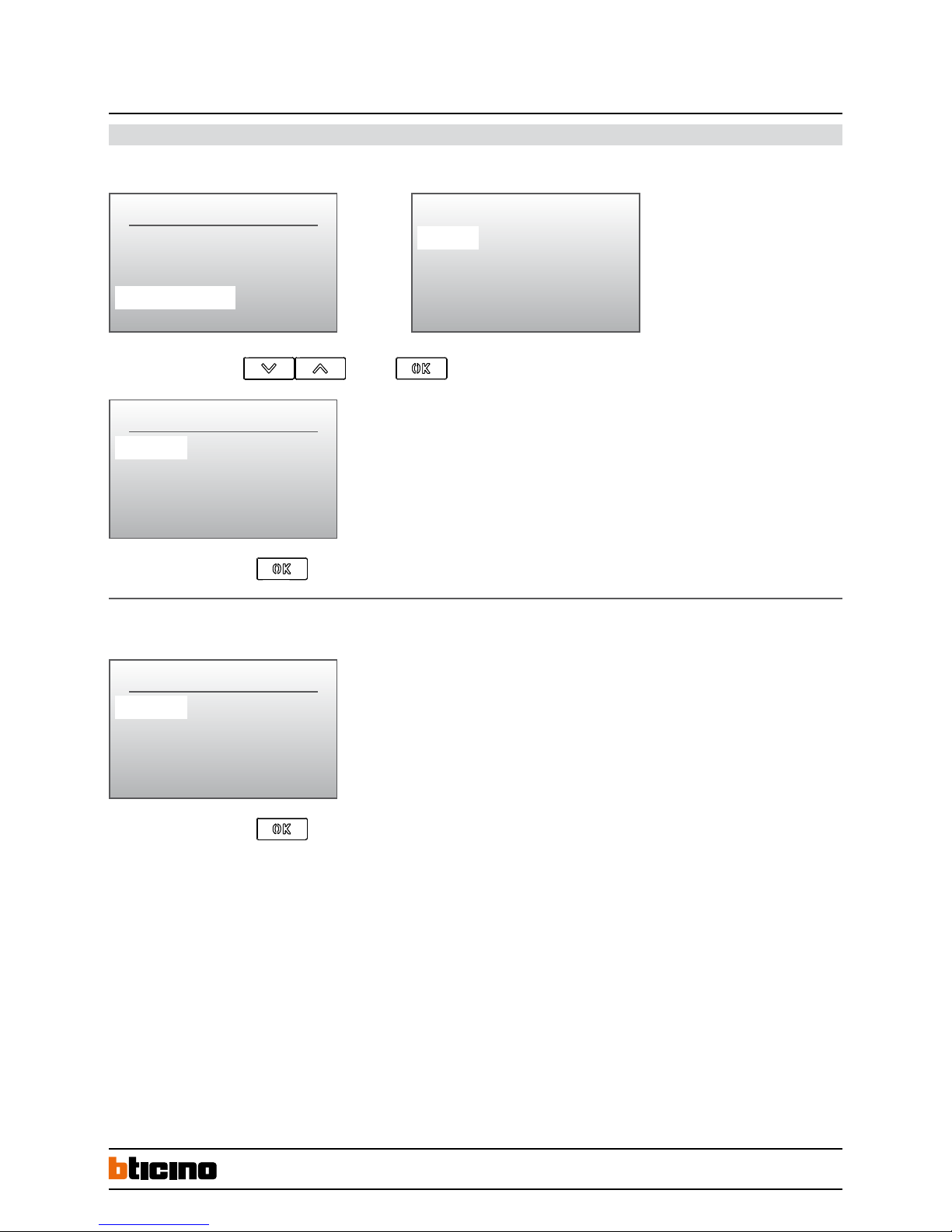
Delete contact - this function gives you the possibility to delete the selected contact.
Delete the adresses book - this function gives you the possibility to delete all the contacts present in the addresses book.
ADDRESS BOOK
New contact
Modify contact
Delete contact
DEL THIS CONTACT
Confirm
Will be deleted
EXIT
DEL ADDRESS BOOK
Confirm
Will be deleted
EXIT
Aaaaa
Bbbbb
Ccccc
Ddddd
Select the contact to delete with than press
Confirm the elimination by pressing
Confirm the elimination by pressing
322011Digital colour entrance panel
with addresses list
BT00853-a-EN 03/09/2014
Page 9
9
Configuration & Settings
Speaker module settings - this configuration can be performed only with the module NOT phisically configured (NO configurators inserted).
SCS SETTINGS
P – Panel number 00
T – Lock time 1
Switchboard 00
FW versions
Phonic mod. : 00.00.00
EXIT
P-Panel number: SCS address of the entrance panel
T-Lock time: door lock time delay (NOT USED)
Switchboard: SCS address of the switchboard (if present)
Signal type of lock: NO = Normally open
NC = Normally closed
Dismantle alarm: ON = alarm enabled
OFF = alarm disabled
Digital colour entrance panel
with addresses list
322011
Firmware version - this menu indicate you the firmware version installed on the device.
Direct call to the switchboard - by pressing the dedicated pushbutton.
Door lock release by code- you can directly activate the door lock releasing by typing the associated numerical code. Press the key
than enter the numerical code.
To call the switchboard
press the button
Input unlock password
Switchboard
DOOR OPEN
BT00853-a-EN 03/09/2014
Page 10
10
S-
S+
C
NC
NO
L+ L
-
NO
NC
C
323020
configuration
tool
1 2
ON
OFF
322011Digital colour entrance panel
with addresses list
322011
346250
Distance 1 2
0 –300 m OFF OFF
300 – 700 m ON OFF
700 – 1000 m ON ON
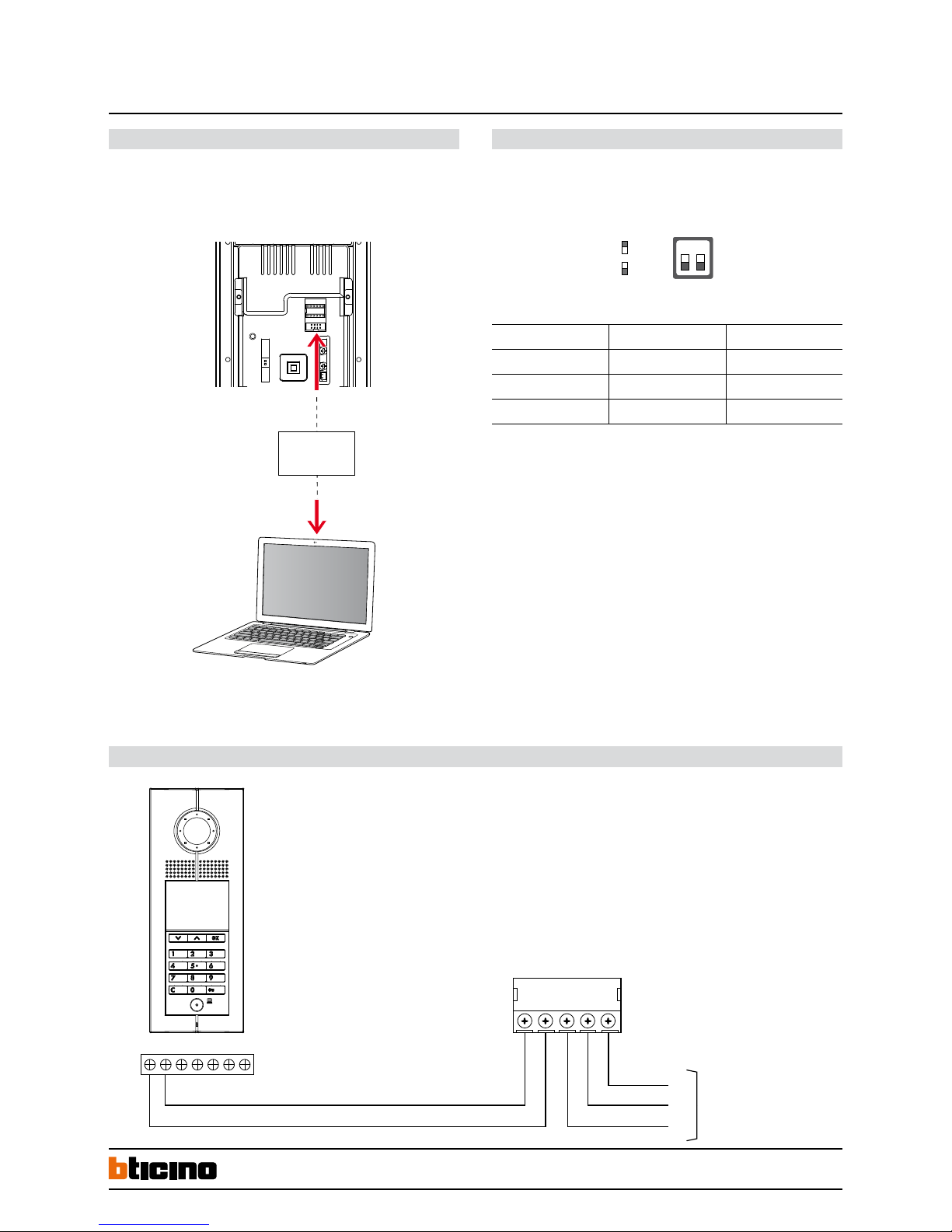
This is the enhanced way to download the device configuration to entrance panel previously created by using SF2 configuration software and a personal computer. To transfer
use the configuration hardware tool 323020 serial interface
Configuration by using SF2 Software and PC connection - WAY 2 :
WARNING : in order for the communication to take place, the EP must be powered and
not physically configured
The entrance panel has a double DIP SWITCH for the video compensation setting.
By setting different DIP V-GAIN, it is possible to adapt the video signal to different
transmission distances - refer as follows :
DIP SWITCH SETTINGS FOR B/W. AND COLOUR SYSTEM
Configuration
Wiring diagrams - Door lock relay connection
N.B.: Cable size 1 mm
2
and max distance 2 meters
8A cosϕ = 1 24 Vac/24 Vdc
4A cosϕ = 0.7 24 Vac
3A cosϕ = 0.4 24 Vac
Video gain settings
BT00853-a-EN 03/09/2014
 Loading...