


User Manual
CPM
Communication Platform

Copyright© 2019 BTG Instruments AB
The contents of this document are subject to revision without notice due to continued progress
in methodology, design, and manufacturing. BTG shall have no liability for any error or
damages of any kind resulting from the use of this document.
All rights reserved. No part of this document may be copied, photocopied, published,
reproduced, translated or converted into electronic or machine-readable form
without written permission of BTG Instruments AB.
Original Instructions
BTG Instruments AB, 2019

Important Information . . . . . . . . . . . . . . . . . . . . . . . . . . . . . 1
1 Product Introduction . . . . . . . . . . . . . . . . . . . . . . . . . . . . . . 3
1.1 General . . . . . . . . . . . . . . . . . . . . . . . . . . . . . . . . . . . . . . . . . . . . . . . . . . .3
1.2 Technical Data . . . . . . . . . . . . . . . . . . . . . . . . . . . . . . . . . . . . . . . . . . . . . 4
1.3 Dimensions and Mounting . . . . . . . . . . . . . . . . . . . . . . . . . . . . . . . . . . . . . 6
1.4 Type Plate Explanations . . . . . . . . . . . . . . . . . . . . . . . . . . . . . . . . . . . . . .7
1.5 CE-Declaration . . . . . . . . . . . . . . . . . . . . . . . . . . . . . . . . . . . . . . . . . . . . 10
2 Installation Instructions . . . . . . . . . . . . . . . . . . . . . . . . . . 11
2.1 Unpacking . . . . . . . . . . . . . . . . . . . . . . . . . . . . . . . . . . . . . . . . . . . . . . . . 11
2.2 Assembly of Product Parts . . . . . . . . . . . . . . . . . . . . . . . . . . . . . . . . . . . 12
2.3 Mounting Instructions . . . . . . . . . . . . . . . . . . . . . . . . . . . . . . . . . . . . . . .13
2.4 Cabling Instructions . . . . . . . . . . . . . . . . . . . . . . . . . . . . . . . . . . . . . . . . . 14
2.5 Connection Instructions . . . . . . . . . . . . . . . . . . . . . . . . . . . . . . . . . . . . . . 14
2.5.1 AC Connection to Power Supply Unit . . . . . . . . . . . . . . . . . . . . . . . . . . 15
2.5.2 HCM-8000 / 8010 Connections . . . . . . . . . . . . . . . . . . . . . . . . . . . . . . . 16
2.5.2.1 HCM-8000 Connections. . . . . . . . . . . . . . . . . . . . . . . . . . . . . . . . . . . . . 17
2.5.2.2 HCM-8010 Connections. . . . . . . . . . . . . . . . . . . . . . . . . . . . . . . . . . . . . 18
2.5.3 FCM-8000 / 8010 Connections . . . . . . . . . . . . . . . . . . . . . . . . . . . . . . . 19
2.5.3.1 FCM-8000 Connections . . . . . . . . . . . . . . . . . . . . . . . . . . . . . . . . . . . . . 20
2.5.3.2 FCM-8010 Connections . . . . . . . . . . . . . . . . . . . . . . . . . . . . . . . . . . . . . 21
2.5.4 Sensor Control Module SCM-8000 . . . . . . . . . . . . . . . . . . . . . . . . . . . . 22
2.5.5 Connection to Transmitter . . . . . . . . . . . . . . . . . . . . . . . . . . . . . . . . . . . 23
2.5.6 24 V On/Off Switch. . . . . . . . . . . . . . . . . . . . . . . . . . . . . . . . . . . . . . . . . 24
2.6 Backup Card . . . . . . . . . . . . . . . . . . . . . . . . . . . . . . . . . . . . . . . . . . . . . .25
2.7 RS-485 Connection . . . . . . . . . . . . . . . . . . . . . . . . . . . . . . . . . . . . . . . . . 26
3 Service Instructions . . . . . . . . . . . . . . . . . . . . . . . . . . . . . 27
3.1 Maintenance Routines . . . . . . . . . . . . . . . . . . . . . . . . . . . . . . . . . . . . . .27
4 Parts List . . . . . . . . . . . . . . . . . . . . . . . . . . . . . . . . . . . . . . 29
4.1 CPM Kits . . . . . . . . . . . . . . . . . . . . . . . . . . . . . . . . . . . . . . . . . . . . . . . . 29
© BTG 2019 User Manual CPM M2066/10en I

5 Appendix . . . . . . . . . . . . . . . . . . . . . . . . . . . . . . . . . . . . . . 31
5.1 HCM-8000 Connections . . . . . . . . . . . . . . . . . . . . . . . . . . . . . . . . . . . . . 31
5.2 HCM-8010 Connections . . . . . . . . . . . . . . . . . . . . . . . . . . . . . . . . . . . . . 33
5.3 FCM-8000 Connections . . . . . . . . . . . . . . . . . . . . . . . . . . . . . . . . . . . . . 35
5.4 FCM-8010 Connections . . . . . . . . . . . . . . . . . . . . . . . . . . . . . . . . . . . . . 37
II User Manual CPM M2066/10en © BTG 2019

Important Information
This user manual contains all necessary instructions for installation,
maintenance, and basic service of the Communication Platform (CPM).
Safety instructions and regulations for installation and service are found in the
BTG Safety Manual, M2076.
NOTE!
Always read the safety instructions before installation and service of the
instrument!
NOTE!
If the CPM is used in a manner not specified by BTG the protection provided
by the equipment may be impaired.
For operation instructions, see the CPM operation manual for the appropriate
instrument. CPM operation manuals are available for the following
instruments:
Instrument CPM Operation manual
ACT-2500
MBT-2500
MEK-2500
MEK-3000
DRT-5500 OM2005
TCR-25xx OM2006
MBT-4500 OM2007
TCT-25x1
RET-25x2
RET-55x3 OM2010
BT-5500 OM2011
BLT-5500 OM2012
SPK-5500 OM2013
DLT-5500 OM2014
RT-5500 OM2015
TCS-2531 OM2016
OCT-25x1 OM2017
SPM-5500 OM2018
SPC-5500 OM2019
OM2003
OM2009
© BTG 2019 User Manual CPM IN2066en Rev.B 1

Recycling
Recycle the instrument and all replaced parts according to local, first and
foremost national, laws and regulations. Contact BTG to get detailed
information on how to disassemble and recycle the instrument safely. BTG
should have no liability for any error or damage of any kind due to disassembly
or recycle work done.
the unit is not falling under the RoHS/WEEE CE-directives according to:
RoHS According to Article 2 (4) and (4e) alt. (4d) and
according to Article 3 (3) alt. (4), the unit shall not
apply to RoHS.
WEEE According to Article 2 (3b) and (4c; f), and according
to Article 3 (1b) and (1c, I, II, III), the unit shall not
apply to WEEE.
2 User Manual CPM IN2066en Rev.B © BTG 2019

Product Introduction
Fig 1 CPM overview
1 Protective cover
2 Front cover
3 Scroll keys
4 LCD display with
backlight
5 Function keys
6 Closing screw
7 Cable glands
8 Transmitter cable
2
3
4
6
7
5
1
8
1 Product Introduction
1.1 General
The CPM is delivered as a complete unit from BTG, normally in conjunction with an
instrument.
The CPM has the following functions:
• Local display and console for full configuration and operation of the
instrument
• Large illuminated display for easy reading
• Protected from splash and sun
© BTG 2019 User Manual CPM PI2066en Rev.B 3

Product Introduction
1.2 Technical Data
General
Type
CPM Communication Platform.
Manufacturer
BTG, Säffle, Sweden.
Quality Assurance
Quality-assured in accordance with ISO 9001.
Product Safety
Fulfills all relevant CE-directive requirements and all Australian TIC requirements.
Function Specifications
Communication Modules:
HCM-8000/8010
Hart communication module using HART® protocol.
Equipped with slot for SD memory card.
Analog output (AO1- AO5)
4 - 20 mA. Galvanic isolated. Current limited to min. 3.9 and max. 20.5 mA.
Loop load signal: Voltage supply/load 24 V DC
Active or passive output for HCM-8000
Active output only for HCM-8010
Superimposed signal over 4 - 20 mA current loop according to standard HART® protocol.
Analog input (AI1 - AI4)
4 - 20 mA 250 Ω input resistance
Digital input (DI1 - DI4)
Galvanic isolated
High-ohmic = logical 0
+24 V ≥ 12 mA = logical 1
Digital output (DO1 - DO2)
Galvanic isolated
Maximum 120 mA
Maximum 30 V DC
Solenoid valve (SV1 - SV5)
Open drain output for solenoids
Maximum 500 mA
Maximum 30 V DC
FCM-8000/8010
Fieldbus communication module programmed for PROFIBUS.
Equipped with slot for SD memory card.
Output / Input signal
PROFIBUS (PA)
User Interface
Illuminated display. Key pad for adjustment of instrument settings.
4 User Manual CPM PI2066en Rev.B © BTG 2019

Product Introduction
Support System Specifications
Supply Voltage
Power supply unit 100 - 240 V AC, 50-60 Hz.
AC input range: 90 - 264 V continuous operation.
Disconnecting Device
An external 2-pole switch close to the CPM is required. The switch must be approved in
accordance with the IEC 60947-2 and IEC 60947-3 requirements.
Power Consumption
Maximum: 135 VA (CPM-1300), 515 VA (CPM-1400), 160 VA (CPM-1500)
Altitude
0 to 2000 m (0-6560ft) without any restrictions.
2000 to 6000 m (6560 to 20000ft) reduce output power or ambient temperature.
Altitude de-rating = 5 W / 1000 m or 5 °C / 1000 m.
Humidity
5 to 95% r.h (IEC 60068-2-30)
Over-voltage Category
Category III: IEC 62103, EN 50178, altitudes up to 2000 m
Category II: altitudes from 2000 m to 6000 m
Degree of Pollution
2: IEC 62103, EN 50178, not conductive
Physical Specifications
Materials
Casing: Polycarbonate thermo plastic
Cable fittings: Polyamide thermo plastic
Storage Temperature
Max. 80 °C (176 °F)
Min. -25 °C (-13 °F)
Operation Temperature
Max. 50 °C (122 °F)
Min. 0 °C (32 °F)
Degree of Protection
IP 65, comparable to NEMA 4x and better, the CPM is intended for use indoors.
Weight
CPM: 2 - 2.5 kg (4.4 - 5.5 lbs) depending on configuration
Cables
Power supply flexible cable: 0.3 - 2.5 mm
Signalling cable: 0.2 - 2.5 mm2 (AWG = 24-12)
Transmitter Cable
CPM-1300: Standard length: 10 m [33 ft] (option up to 55 m [180 ft])
Cable diameter: 5.5 mm [0.22"]
Connector diameter: 15 mm [0.6"]
CPM-1400: Standard length: 10 m [33 ft] (option up to 20 m [66 ft])
Cable diameter: 13 mm [0.5"]
No fixed connector
CPM-1500: Standard length: 10 m [33 ft] (option up to 20 m [66 ft])
Cable diameter: 5.5 mm [0.22"]
No fixed connector
2
(AWG = 28-12)
Cable Inlets
There are cable glands for signal cables (diameter 4-8 mm) and for power supply cable
(diameter 4-12 mm) in the bottom of the CPM.
© BTG 2019 User Manual CPM PI2066en Rev.B 5

Product Introduction
210
8.4"
10 (4x)
0.4"
5 (4x)
0.2"
10
0.4"
180
7.2"
240
9.6"
270
10.8"
180
7.2"
152
6"
162
6.5"
222
8.9"
50
2"
Quick GuideQuick
Guide
180
7.2"
Fig 2 Dimensions
300
12"
200
8"
200
8"
Quick GuideQuick
Guide
200
8"
Fig 3 Recommended
clearances
1.3 Dimensions and Mounting
6 User Manual CPM PI2066en Rev.B © BTG 2019

Product Introduction
N1619
NiMH
Certified to CAN/CSA-C22.2 No.61010-1 2nd ed
BTG Instruments AB
Industrigatan 1-3
66129 Säffle
SWEDEN
PRODUCT
VOLTAGE
FREQUENCY
NO
TYPE
3068754
INSTALLATION CATEGORY
FACTORY IDENTIFICATION
APPARENT POWER
Fig 4 Type plate
HA/Q0/C0/S/10/I230 A
123456
50-60 Hz
12345
6
7
8
9
10 11
12
50 W
III
CPM-1300
100-240 V AC
15
13
14
16
1.4 Type Plate Explanations
1. Manufacturer
2. CE-marking
The CPM is approved in accordance with CE directives.
3. C-TIC marking
The CPM is approved in accordance with Australian C-TIC N1619
directives.
4. ETL-marking
The CPM is approved by ETL.
5. Warning sign
The CPM is designed for industrial use. Installation, handling and service
must only be carried out by trained and authorized personnel and in
accordance with relevant standards. Read the manual for detailed
information and pay particular attention to the warning signs!
© BTG 2019 User Manual CPM PI2066en Rev.B 7

Product Introduction
CPM-1300
ABC
6. Product
The instrument model is specified according to the code system explained
below:
A Product Group
CPM Communication platform
B Power type
13 50 W Power supply
14 240 W Power supply
15 80 W Power supply
C Input/Output Unit
If field D = Hx:
1x analog output, 1x analog input
00
10
1x digital output, 3x digital inputs
If field D = PA or FF:
1x Fieldbus output
1x digital output, 1x digital input
If field D = HA
5x analog outputs, 4x analog inputs
7x digital outputs, 4x digital inputs
7. Manufacturing number
BTG internal product identification number.
8. Frequency
The CPM operates at both 50 and 60 Hz.
9. Apparent power
Maximum power consumption (W).
10. Installation category
In accordance with CE-Directive. Fixed installation. Resistant to
transients.
11. Factory identification
12. Voltage
100-240 V AC to power supply.
13. Recycling
The CPM should be recycled in accordance with local regulations.
8 User Manual CPM PI2066en Rev.B © BTG 2019

Product Introduction
HA/Q0/C0/S/10/I230 A
DEFG HI
14. Type specification
The instrument variant is specified according to the code system
explained below:
D Communication Protocol
HA Analog 4-20 mA with HART
Hx
PA Profibus PA
FF Foundation Fieldbus
F0 Foundation Fieldbus supplied with FCI-1000
Q0 No module
Q1 Sensor control module SCM-8000
C0 No serial connector
C1 One serial connector
C2 Two serial connectors
S Standard housing with protecting cover
T Standard housing without protecting cover
L Large housing without protecting cover
10 10 m [32.8 ft]
20 20 m [65.6 ft]
30 30 m [98.4 ft]
40 40 m [131.2 ft]
55 55 m [180.4 ft]
I012 Interlock interface relay 12 V DC
I024 Interlock interface relay 24 V AC/DC
I048 Interlock interface relay 48 V DC
I060 Interlock interface relay 60 V DC
I120 Interlock interface relay 120 V AC/ 110 V DC
I230 Interlock interface relay 230 V AC/ 220 V DC
A Alarm relay max 230 V AC / 220 V DC
Analog 4-20 mA with HART
but can be set by customer from menu to: Passive output
E Sensor Control Module
F Communication Connector
G Housing
H Cable length
I Other options
Blank = no option
®
, Active output
®
, Standard is: Active output
15. Waste electricals
Do not place electrical items in the general waste, recycle in accordance
with local regulations.
16. QR code
QR code to scan for more information about the CPM on the site:
www.btg.com/mybtg/en/instruments/cpm.
© BTG 2019 User Manual CPM PI2066en Rev.B 9

Product Introduction
Declaration of Conformity
CE mark
COMMUNICATION PLATFORM
TYPE: CPM-1300
CPM-1400
CPM-1500
BTG INSTRUMENTS AB
P.O. Box 602
661 29 Säffle
Sweden
This declaration of conformity is issued under the sole responsibility of the manufacturer.
We declare that the above Communication Platform conforms to:
2014/35/EU Low Voltage Directive, LVD
2014/30/EU Electromagnetic Directive, EMC
2014/68/EU Pressure Equipment Directive, PED
The following harmonized standards have been practiced:
IEC/EN 61010-1:2010 Safety requirements for electrical equipment for measurement, control, and laboratory
use - Part 1: General requirements
EN ISO 12100:2010 Safety of machinery - General principles for design - Risk assessment and risk
reduction
EN 61326-1:2013 Electrical equipment for measurement, control and laboratory use - EMC requirements
Part 1: General requirements
Authorized Signature:………………………………… Date: 2018-03-01……………………
Name: Björn Fahlin…………………………………... Position: Director of Operations
1.5 CE-Declaration
When using the units in combinations other than those tested for, BTG can not
guarantee CE-directive conformity.
The units in combination with customer-installed external devices may conform
with EMC and safety requirements when properly installed and CE-marked
equipment is used.
The system operator is responsible for CE-directive conformity.
Conformity must be verified by inspection.
10 User Manual CPM PI2066en Rev.B © BTG 2019

Installation Instructions
2 Installation Instructions
2.1 Unpacking
The following is included in a CPM delivery:
1. 1 x CPM box with transmitter cable
2. 1 x Protection cover (not when pre-assambled on a base unit)
3. 1 x Quick reference guide card
© BTG 2019 User Manual CPM II2066en Rev.B 11

Installation Instructions
Quick Guide
Fig 5 Quick Reference
Guide
Slot for Quick
Reference Guide card
Quick Reference
Guide card
2.2 Assembly of Product Parts
The protection cover is equipped with a slot for the Quick Reference Guide
(QRG) card, which is enclosed with certain transmitters. If a QRG card of the
type shown in Fig 5 is enclosed with your transmitter, place it in the slot as
shown in Fig 5.
12 User Manual CPM II2066en Rev.B © BTG 2019

Installation Instructions
300
12"
200
8"
200
8"
Quick GuideQuick
Guide
200
8"
Fig 6 Recommended
clearances
2.3 Mounting Instructions
Tools required:
Screwdriver
Drilling machine
1. Mount the CPM in the selected location by fastening the protective cover
to a flat surface. Use four suitable screws.
• See Fig 6 for recommended clearances.
• The top of the protective cover can be used as a holder for a
HART-terminal.
© BTG 2019 User Manual CPM II2066en Rev.B 13

Installation Instructions
DANGER
Hazardous voltage
in the equipment
2.4 Cabling Instructions
NOTE!
BTG recommends that separate cables be used for analog and digital signals.
Multi conductor cables can be used.
NOTE!
Unused cable glands must be sealed in order to fulfill the IP 65 requirement.
2.5 Connection Instructions
All electrical connections are made inside the CPM.
To access the terminal blocks, loosen the two screws on the right side of the
front cover and open the CPM.
NOTE!
Secure all cables with cable ties to avoid short circuit.
14 User Manual CPM II2066en Rev.B © BTG 2019

Installation Instructions
DANGER
Hazardous voltage
in the equipment
++
--
100 240 V AC-
N
L
50W
+
+
--
NL
100 240 V AC-
PE N L
N
L
+ +
- -
AC
100-120/
200-240 V
AC
100-120/
200-240 V
+
+
--
NL
PENL
AC
100-120/
200-240 V
Fig 7 Connection of AC
cable
Fuse
Min. 4 A (200-240 V)
Min. 6 A (100-120 V)
Fuse
Min. 2 A
2.5.1 AC Connection to Power Supply Unit
A specific instruction manual for the power supply unit can be found inside the
CPM box.
NOTE!
Before installation, ensure that all power to the system has been turned off.
Cable connections must be made by authorized personnel.
NOTE!
Overcurrent protection is included in the power supply unit.
NOTE!
An external 2-pole switch close to the CPM is required as shown in Fig 7
(Not delivered from BTG).
The switch should be marked "Disconnecting device".
NOTE!
The connection cable must be able to withstand an ambient temperature of at
least 75 °C (167 °F).
1. Insert the power supply cable through the cable gland.
2. Connect the AC cable (100 - 240 V AC, 50-60 Hz) to the power supply unit
as shown in Fig 7.
© BTG 2019 User Manual CPM II2066en Rev.B 15

Installation Instructions
DANGER
Hazardous voltage
in the equipment
Fig 8 Analog Out 4-20 mA
Analog Out (DCS) 4-20 mA
0
814
250
35 (Max)
V
730
1200
W
24
A
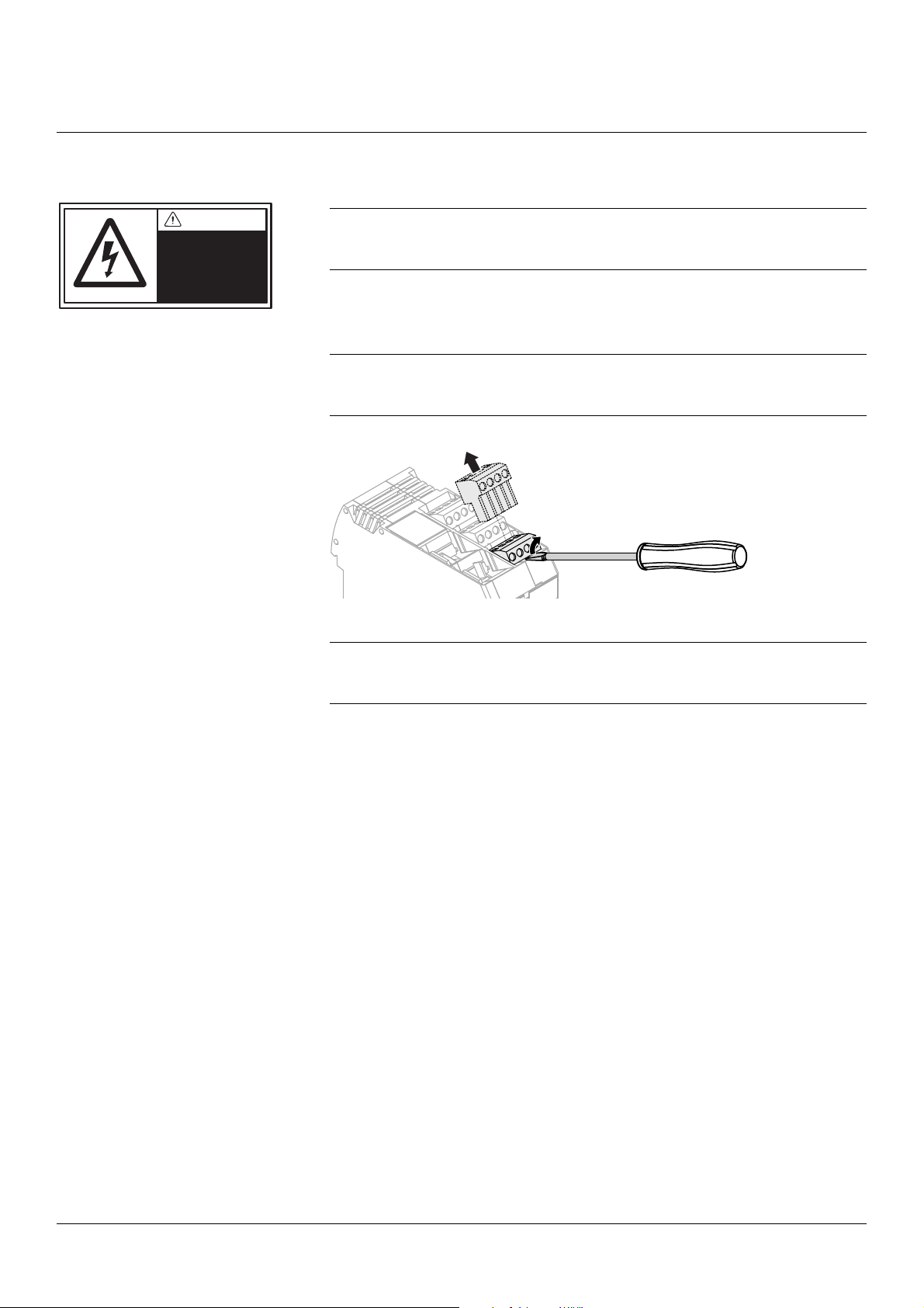
Fig 9 Releasing the
connection blocks
2.5.2 HCM-8000 / 8010 Connections
The Hart communication module (HCM-80xx) is using HART® protocol.
NOTE!
Before installation, ensure that all power to the system has been turned off.
Cable connections must be made by authorized personnel.
NOTE!
Fig 8 shows resistance as a function of supply voltage. The grey area is
accepted. The resistance is the sum of cable- and power source- resistance in
the current loop. The HART
250
®
communication requires a minimum resistance of
1. Insert the signal cable through the cable gland.
2. Connect the cable to the HCM-80xx as shown in Fig 11 or Fig 13.
NOTE!
The connection blocks can be released from the connection module for easier
access, as shown in Fig 9 below.
3. Connect the shield to the upper connection point on the shield filter module
(SFM-8000).
CAUTION!
The cable shield must always be connected to the upper connection point on
the shield filter module, and kept separated from the transmitter cable shield.
16 User Manual CPM II2066en Rev.B © BTG 2019

Installation Instructions
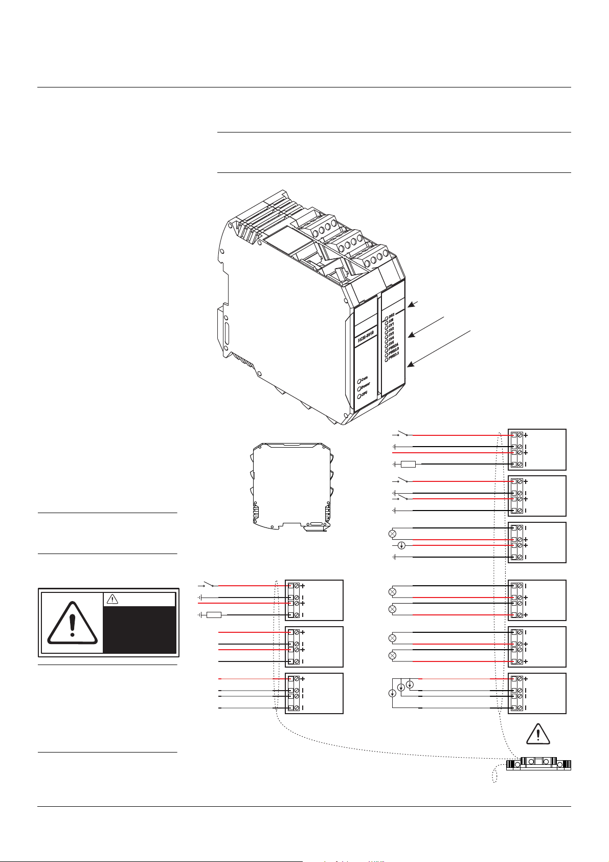
P1
P3
P2
Fig 10 HART Communication
Module HCM-8000
HCM-8000
P3
P2
P1
AO Analog Out( ) alternatives
Alternative 1: AO = Passive
Alternative 2: AO = Active
Transmitter
cable
Cable shield
SFM-8000
Digital In 3
Digital Out
DI3
P1
DO
+
-
LOAD
+24 V
+24 V
Digital In 2
Digital In 1
DI1
P2
DI2
+24 V
+24 V
Analog In 4-20 mA
Active Analog Out 4-20 mA
AO1
P3
AI1
+24 V
Analog In 4-20 mA
Passive 4-20 mAAnalog Out
Supplied with 14 - 35 V DC
AO1
P3
AI1
+24 V
+
-
LOAD
+24 V
Fig 11 Connection of HCM-
8000 cable
CAUTION
Always connect
the cable shield!
CAUTION!
The cable shield must always
be connected to the upper
connection point on the shield
filter module, and kept
separated from the transmitter
cable shield.
NOTE!
Note the polarity for
Passive or Active
Analog Out (AO).
If the analog output
signal (4-20 mA) is
passive, an external
source of current must
be used (14-35 V DC)
2.5.2.1 HCM-8000 Connections
NOTE!
The functions of the connections for each instrument type can be found in the
connection tables for HCM-8000 in section 5: Appendix
© BTG 2019 User Manual CPM II2066en Rev.B 17
Installation Instructions
P1
P3
P2
P4
P6
P5
P7
P9
P8
Fig 12 HART Communication
Module HCM-8010
P3
HCM-8010
P2
P1
P4
P5
P6
P7
P8
P9
Digital In 2
Digital In 1
Digital In 3
Digital Out
Analog In 4-20 mA
Active Analog Out 4-20 mA
Active Analog Out 2 (4-20 mA)
Active Analog Out 3 (4-20 mA)
Active Analog Out 4 (4-20 mA)
Active Analog Out 5 (4-20 mA)
Digital In 4
Digital Out 2
Solenoid Valve 4
Solenoid Valve 5
Transmitter
cable
Cable shield
SFM-8000
DI3
P1
DO
DI1
P2
DI2
AO1
P3
AI1
AO2
P4
AO3
AO4
P5
AO5
AI
P6
23 4
DI4
P7
DO2
SV4
P8
SV5
SV
P9
12 3
+
-
LOAD
+24 V
+24 V
+24 V
+24 V
+24 V
Analog In 2 (4-20 mA)
Analog In 3 (4-20 mA)
Analog In 4 (4-20 mA)
Common +24 V
+24 V
Solenoid Valve 1
Common +24 V
Solenoid Valve 2
Solenoid Valve 3
+
-
LOAD
+24 V
Fig 13 Connection of
HCM-8010 cables
CAUTION
Always connect
the cable shield!
CAUTION!
The cable shield must always
be connected to the upper
connection point on the shield
filter module, and kept
separated from the transmitter
cable shield.
NOTE!
For HCM-8010, only active
analog output is available.
2.5.2.2 HCM-8010 Connections
NOTE!
The functions of the connections for each instrument type can be found in the
connection tables for HCM-8010 in section 5: Appendix
18 User Manual CPM II2066en Rev.B © BTG 2019
Installation Instructions
DANGER
Hazardous voltage
in the equipment
Fig 14 Releasing the
connection blocks
2.5.3 FCM-8000 / 8010 Connections
NOTE!
Before installation, ensure that all power to the system has been turned off.
Cable connections must be made by authorized personnel.
1. Insert the signal cables through the cable glands.
2. Connect the cables to the FCM-80xx as shown in Fig 11 or Fig 13.
NOTE!
The connection blocks can be released from the connection module for easier
access, as shown in Fig 14 below.
3. Connect the shield to the upper connection point on the shield filter module.
CAUTION!
The cable shield must always be connected to the upper connection point on
the shield filter module, and kept separated from the transmitter cable shield.
© BTG 2019 User Manual CPM II2066en Rev.B 19

Installation Instructions
P1
P3
P2
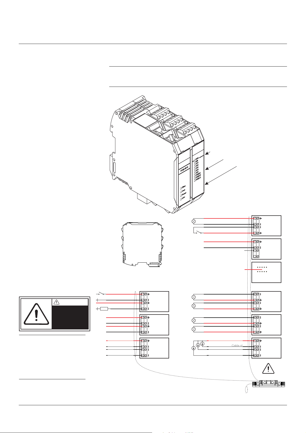
Fig 15 Fieldbus Communication
Module FCM-8000
P3
FCM-8000
P2
P1
Transmitter
cable
Cable shield
SFM-8000
Shield
FF / PROFIBUS PA
Digital In 3
Digital Out
DI3
P1
DO
1
P2
2
P3
3
4
S
Software update
Fig 16 Connection of
FCM-8000 cables
CAUTION
Always connect
the cable shield!
CAUTION!
The cable shield must always
be connected to the upper
connection point on the shield
filter module, and kept
separated from the transmitter
cable shield.
2.5.3.1 FCM-8000 Connections
NOTE!
The functions of the connections for each instrument type can be found in the
connection tables for FCM-8000 in section 5: Appendix
20 User Manual CPM II2066en Rev.B © BTG 2019
Installation Instructions
P1
P3
P2
P4
P6
P5
P7
P9
P8
Fig 17 Fieldbus Communication
Module FCM-8010
P3
FCM-8010
P2
P1
P4
P5
P6
P7
P8
P9
Transmitter
cable
Cable shield
SFM-8000
Cable shield
Shield
FF / PROFIBUS PA
Digital In 3
Digital Out
DI3
P1
DO
1
P2
2
P3
3
4
S
Software update
Active Analog Out 2 (4-20 mA)
Active Analog Out 3 (4-20 mA)
Active Analog Out 4 (4-20 mA)
Active Analog Out 5 (4-20 mA)
AO2
P4
AO3
AO4
P5
AO5
AI
P6
23 4
Analog In 2 (4-20 mA)
Analog In 3 (4-20 mA)
Analog In 4 (4-20 mA)
Common +24 V
Solenoid Valve 4
Solenoid Valve 5
SV4
P8
SV5
SV
P9
12 3
Solenoid Valve 1
Common +24 V
Solenoid Valve 2
Solenoid Valve 3
Digital In 4
Digital Out 2
DI4
P7
DO2
+24 V
+
-
LOAD
+24 V
Fig 18 Connection of
FCM-8010 cables
CAUTION
Always connect
the cable shield!
CAUTION!
The cable shield must always
be connected to the upper
connection point on the
shield filter module, and kept
separated from the
transmitter cable shield.
2.5.3.2 FCM-8010 Connections
NOTE!
The functions of the connections for each instrument type can be found in the
connection tables for FCM-8010 in section 5: Appendix
© BTG 2019 User Manual CPM II2066en Rev.B 21

Installation Instructions
DANGER
Hazardous voltage
in the equipment
HCM
8000
DI3
DO
+- +-
+- +-
+- +-
DI1 DI2
AO AI
P1
P2
P3
RS-485
red
black
blue
white
+- +-
+- +-
+- +-
P1
P2
P3
+- --
+- --
+- --
P6
P5
P4
SCM-8000
Common
Solenoid valve 2
Solenoid valve 3
Solenoid valve 5
Solenoid valve 6
Solenoid valve 7
Solenoid valve 4
Solenoid valve 9
Solenoid valve 8
Solenoid valve 1
-+-
P4
-
+
-
P6
-
+
-
P5
-
--
Sensor Cable
SCM-8000
-
+
-
+
P3
Sample button
Sampling indicatior +24 V
-
+
-
+
P2
-
+
-
+
P1
brown
black
white
blue
HCM-8000
P1
P2
P3
P4
P5
P6
SCM-8000
SCM
8000
Fig 19 Connection of
SCM-8000
2.5.4 Sensor Control Module SCM-8000
NOTE!
These connection instructions are only valid for DRT-5500. Other instruments
equipped with the SCM-8000 have all connections to the SCM unit pre-wired
at delivery.
NOTE!
Before installation, ensure that all power to the system has been turned off.
Cable connections must be made by authorized personnel.
22 User Manual CPM II2066en Rev.B © BTG 2019

Installation Instructions
DANGER
Hazardous voltage
in the equipment
+-+
-
White
Blue or Yellow
Brown
Black or Green
Cable shield
24 V DC
RS-485
1kΩ
SFM-8000
Fig 20 CPM-1300 cable to
transmitter
N
L
AC
100-120/
200-240 V
2
3
4S
SAB
On/Off
Red
Black
Blue
White
Fig 21 CPM-1400 cable to
transmitter
2.5.5 Connection to Transmitter
NOTE!
Before installation, ensure that all power to the system has been turned off.
Cable connections must be made by authorized personnel.
The pre-assembled cable is connected to the transmitter according to the
installation instruction for the transmitter.
Fig 20 shows the pre-assembled transmitter cable-connection inside the
CPM-1300.
© BTG 2019 User Manual CPM II2066en Rev.B 23
Fig 21 shows the transmitter cable-connection inside the CPM-1400
(for MEK-3000).

Installation Instructions
N
L
++
--
AC
100-120/
200-240 V
2
3
4S
SAB
On/Off
Fig 22 24 V On/Off switch
2.5.6 24 V On/Off Switch
Some CPM models are equipped with a fuse used as an On/Off switch for the
24 V supply to the CPM and the transmitter. Fig 22 shows the 24 V On/Off
switch in the CPM-1400 for MEK-3000.
24 User Manual CPM II2066en Rev.B © BTG 2019

Installation Instructions
SD
M
e
m
o
ry
C
a
rd
+-+
-
-
+
-
+
Communication
module
Fig 23 Location of SD card
reader
2.6 Backup Card
The HCM-8000 and FCM-8000 is equipped with a slot for a memory card of
the type Secure Digital (SD). A SD card is not included in a CPM delivery.
All transmitter settings, transmitter data, and calibration data can be stored on
a SD card. The SD card reader is located on the communication module card,
and can be accessed by opening the front cover of the CPM (see Fig 23).
© BTG 2019 User Manual CPM II2066en Rev.B 25

Installation Instructions
RS-485
Fig 24 RS-485 connections
1 Software update and
temporary
communication
2 Primary communication;
BTG Software (Only on
certain CPM models)
2
1
2.7 RS-485 Connection
26 User Manual CPM II2066en Rev.B © BTG 2019

Service Instructions
3 Service Instructions
3.1 Maintenance Routines
No regular maintenance is required for the CPM apart from keeping the unit
clean and free from pulp.
© BTG 2019 User Manual CPM SI2066en Rev.A 27

Service Instructions
28 User Manual CPM SI2066en Rev.A © BTG 2019

4 Parts List
+-+
-
NL
PE
POWER
SUPPLY
HCM-8000
HCM-8000
Com
Power
CPU
Pulptec
TM
1
5
2
6
4
3
7
Parts List
Most spare parts are delivered in kits. Each kit includes instructions.
4.1 CPM Kits
Kit
No.
Rec.
spare
Qty Part No. Spare Part Description
parts
1 1 PB0011007 Console kit
Without electronics Including:
Protective cover, Display holder, Front
tape, Attachments
Hart communication module Including:
2 1 PB0011015 HCM-8000 kit
PB0011023 Transmitter cable kit (CPM-1300)
31
P46033742 Transmitter cable (CPM-1400)
4 1 HB0011031 50 W power supply kit Including: Cable, Contact (2 pin)
5 1 PB0011049 Display card kit Including: Cable
Bottom socket, Contact for transmitter
(5 pin)
Standard 10 m
(other length on request)
MEK-3000 up to 20 m
(not shown in figure)
6 1 PB0011056 SFM-8000 kit Shield filter module kit
7 1 HB0011171 4-20 mA Active output kit
© BTG 2019 User Manual CPM PL2066en Rev.A 29

Parts List
N
L
++
--
AC
100-120/
200-240 V
2
3
4S
SAB
On/Off
SCM-8000
SCM-8000
Com1
Power
CPU
Pulptec
TM
Com2
SV6
SV5
SV4
SV3
SV2
SV1
HCM-8000
HCM-8010
HCM-8010
Pulptec
TM
HCM-8000
Com
Power
CPU
Pulptec
TM
DO2
DI4
SV1
SV3
POWER 5.0
POWER 24
POWER 3.3
SV2
DI51
DO3
HCM-8000
FCM-8000
Com
Power
CPU
Pulptec
TM
89 10 11 12 13
Kit
No.
Rec.
spare
parts
Qty Part No. Spare Part Description
Fieldbus communication module,
PB0011551 FCM-8000 kit
81
programmed for PROFIBUS (PA)
Including: Bottom socket, Contact for
transmitter (5 pin).
Fieldbus communication module,
PA0113415 FCM-8010 Unit
programmed for PROFIBUS (PA) for
extended in- and outputs
9 1
PB0021741 240 W Power Supply kit For CPM-1400 (MEK-3000)
P46036133 80 W Power Supply unit For CPM-1500 (SPK-5500)
10 1 P46033965 24 V Switch 24 V Switch
11 1 Terminal Block kit For CPM-1400 (MEK-3000)
Hart Communication Module with
12 1 PB0021774 HCM-8000/8010 kit
8010 card for extended in- and outputs
Including: Bottom sockets 5 pin x2
13 1 KB0021782 SCM-8000 kit
Sensor Control Module
Including: Bottom socket 5 pin
14 1 HA0111674 Communication cable RS-485 Serial (not in figure)
15 1 HA0112953 Communication cable RS-485 USB (not in figure)
16 1 PA0150151 RS485 service connector (not in figure)
17 * 1 P00X20418 SD card 512 MB Industrial
Memory card for back-up
(not in figure)
18 1 PA0174573 Alarm relay Kit (not in figure)
19 1 PA0119867 Interlock relay Kit (not in figure)
30 User Manual CPM PL2066en Rev.A © BTG 2019

5 Appendix
Appendix
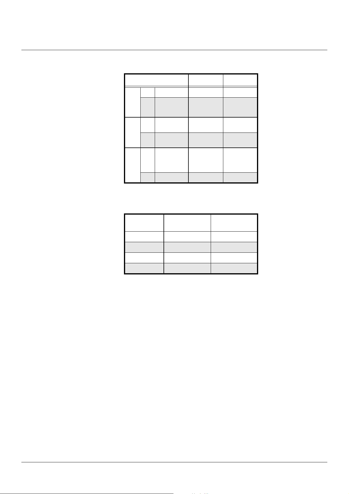
5.1 HCM-8000 Connections
Connection Block ACT-2500 DRT-5500 MBT-2500 MBT-4500
DI3 Digital In 3 Sample Input
P1
DO Digital Out Alarm Output Data Ready Alarm Output Alarm Output
DI1 Digital In 1
P2
DI2 Digital In 2
AO Analog Out
P3
AI Analog In Not used Not used Not used
Calibration set
Input A
Calibration set
Input B
Consistency
output value
4 - 20 mA
Interlock
(1=Interlock)
Calibration set
Input A
Calibration set
Input B
Freeness
output value
4 - 20 mA
Sample Input Sample Input
Calibration set
Input A
Calibration set
Input B
Consistency
output value
4 - 20 mA
Calibration set
Input A
Calibration set
Input B
Viscosity
output value
4 - 20 mA
Temperature
or Flow input
4 - 20 mA
Connection Block MEK-2500 MEK-3000 OCT-25x1 TCR-25x1
DI3 Digital In 3 Sample Input
P1
DO Digital Out Alarm Output Alarm Output Alarm Output Alarm Output
DI1 Digital In 1
P2
DI2
Digital In 2
Calibration set
Input A
Calibration set
Input B
Sample Input
or Interlock
Calibration set
Input A
Calibration set
Input B
Sample Input Sample Input
Calibration set
Input A
Calibration set
Input B
Calibration set
Input A
Calibration set
Input B
AO Analog Out
P3
AI Analog In Not used Not used Not used Not used
Consistency
output value
4 - 20 mA
Consistency
output value
4 - 20 mA
Total
Consistency
output value
4 - 20 mA
Total
Consistency
output value
4 - 20 mA
© BTG 2019 User Manual CPM AX2066en Rev.B 31
Appendix
Connection Block TCS-2531 TCT-25x1
DI3 Digital In 3 Sample Input Sample Input
P1
DO Digital Out Alarm Output
DI1 Digital In 1
P2
DI2
Digital In 2
AO Analog Out
P3
AI Analog In Not used Not used
Calibration set
Input A
Calibration set
Input B
Total
Consistency
output value
4 - 20 mA
Calibration Set configuration
Calibration
Set
10 0
2 1 0
30 1
4 1 1
Input A
(Digital In 1)
Input B
(Digital In 2)
Alarm Output
or PCD-1000
control
Calibration set
Input A
Calibration set
Input B
Total
Consistency
output value
4 - 20 mA
32 User Manual CPM AX2066en Rev.B © BTG 2019

Appendix
5.2 HCM-8010 Connections
Connection Block
DI3 Digital In 3 Initiate lab sample Sample Input Sample Input Interlock
P1
DO Digital Out 1 Alarm Output Alarm Output
DI1 Digital In 1 Calibration set Input A Calibration set Input A Calibration set Input A Calibration set Input A
P2
DI2 Digital In 2 Calibration set Input B Calibration set Input B Calibration set Input B Calibration set Input B
AO Analog Out 1
P3
AI Analog In1
AO2 Analog Out 2
P4
AO3 Analog Out 3
AO4 Analog Out 4
P5
AO5 Analog Out 5
BT-5500
BLT-5500
Channel 1 output value
4 - 20 mA
Analog input signals
from external equipment
4 - 20 mA
Channel 2 output value
4 - 20 mA
Channel 3 output value
4 - 20 mA
Channel 4 output value
4 - 20 mA
Channel 5 output value
4 - 20 mA
DLT-5500 RET-25x2 RET-55xx
Alarm Output or PCD1000 control
Dissolved lignin
(Channel 1) output value
4 - 20 mA
Not used Not used Not used
Total consistency
(Channel 2) output value
4 - 20 mA
Not used Not used Not used
Not used Not used Not used
Total consistency
(Channel 1) output value
4 - 20 mA
Ash consistency
(Channel 2) output value
4 - 20 mA
Alarm Output
Total consistency
(Channel 1) output value
4 - 20 mA
Ash consistency
(Channel 2) output value
4 - 20 mA
(RET-55x3 only)
AI2 Analog In 2
P6
AI4 Analog In 4
DI4 Digital In 4
P7
DO2 Digital Out 2
SV4 Sol. valve 4
P8
SV5 Sol. valve 5
SV1 Sol. valve 1
P9
SV2 Sol. valve 2
SV3 Sol. valve 3
(a) For more information about internally pre-wired connections, see the installation drawing for the transmitter
Analog input signals
from external equipment
4 - 20 mA
Not used Not used Not used
Nut used Not used Not used
Not used Not used Not used
Not used Not used Not usedAI3 Analog In 3
Internally pre-wired
Internally pre-wired
Internally pre-wired
(a)
(a)
(a)
© BTG 2019 User Manual CPM AX2066en Rev.B 33

Appendix
Connection Block RT-5500 SPC-5500 SPM-5500 SPK-5500 TCR-25x2
DI3 Digital In 3 Sample Input Interlock Interlock Remote stop Sample Input
P1
Digital Out 1
Floating DC
DO
switch max 30 V,
100 mA
DI1 Digital In 1
Alarm Output Alarm Output Alarm output Alarm Output Alarm Output
Calibration set
Input A
P2
DI2 Digital In 2
AO Analog Out 1
Calibration set
Input B
Residual (Channel
1) output value
4 - 20 mA
P3
Analog input
AI Analog In1
AO2 Analog Out 2
signals from
external equipment
4 - 20 mA
Conductivity
(Channel 2) output
value
4 - 20 mA
P4
Media temp.
AO3 Analog Out 3
(Channel 3) output
value
4 - 20 mA
AO4 Analog Out 4
P5
Not used
AO5 Analog Out 5 Not used
Not used Not used Calibration set Input A
Not used Not used Calibration set Input B
Filtrate charge
(Channel 1) output
value
4 - 20 mA
Configurable
(Channel 1) output
value
4 - 20 mA
Kappa
LRV - URV
output value
4 - 20 mA
Calibration set
Input A
Calibration set
Input B
Total consistency
(Channel 1) output
value
4 - 20 mA
Not used Not used Not used Not used
White water charge
(Channel 2) output
value
4 - 20 mA
Start streaming
potential for filtrate
(Channel 1)
Start streaming
potential for white
water (Channel 2)
Configurable
(Channel 2) output
value
4 - 20 mA
Configurable
(Channel 3) output
value
4 - 20 mA
Internally pre-
(a)
wired
RMS 0-0.0015 V
output value
4 - 20 mA
CwZ 0-1.65 V
output value
4 - 20 mA
CwT 0-0.165 V
output value
4 - 20 mA
Mean Kappa
LRV - URV
output value
4 - 20 mA
(b)
Ash consistency
(Channel 2) output
value
4 - 20 mA
Not used
Not used
Analog input
AI2 Analog In 2
P6
AI3 Analog In 3
signals from
external equipment
4 - 20 mA
Not used
Internally pre-
(a)
wired
Internally
pre-wired
Not used
AI4 Analog In 4 Not used
DI4 Digital In 4
P7
DO2
SV4 Sol. valve 4
P8
SV5 Sol. valve 5
SV1 Sol. valve 1
P9
SV2 Sol. valve 2
Digital Out 2
Floating DC
switch max 30 V,
100 mA
Not used
Not used
Data ready
Channel 1
Not used Not used
Data ready
Channel 2
Not used
Not used
Internally pre-
(a)
wired
Sample Input
Not used Data Ready
Internally pre-
(a)
wired
Internally pre-wired
Not used
Internally pre-
(a)
wired
Internally pre-wired
SV3 Sol. valve 3
(a) For more information about internally pre-wired connections, see the installation drawing for the transmitter
(b) Average since last start. Normally only used for batch applications
(a)
Not used
Not used
(a)
Not used
(a)
Not used
34 User Manual CPM AX2066en Rev.B © BTG 2019

Appendix
5.3 FCM-8000 Connections
ACT-2500
BLT-5500
BTT-5500
Connection Block
DLT-5500
MBT-2500
MBT-4500
MEK-2500
RT-5500
TCR-25xx
DRT-5500 MEK-3000
TCT-25x1
RET-25x2
DO Digital Out Alarm Output Data Ready Alarm Output
P1
DI3 Digital In 3 Sample Input
P2 FF / PROFIBUS PA
See separate table below for data between Profibus and
Transmitter
Interlock
(1 = interlock)
Data Between Profibus and transmitter
Profibus
AI1 AO
AI2
AI3 AO3 Not used
Trans
mitter
AO2 Not used
ACT-2500
MBT-2500
MEK-2500
MEK-3000
Consistency
output
BT-5500
BLT-5500
Channel 1
output
Channel 2
output
Channel 3
output
DLT-5500 DRT-5500 MBT-4500
Dissolved
lignin
(Channel 1)
output
Total
consistency
(Channel 2)
output
Not used Not used Not used
Alarm Output
or PCD-1000
control
Sample Input
or Interlock
Freeness
output
Not used Not used
Sample Input
Viscosity
output
AI4
AI5 AO5 Not used
AI6 AO6 Not used
AO1 AI Not used
DI DO
DO1 DI1
DO2 DI2
DO3 DI3
AO4 Not used
Alarm Out
Calibration
set Input A
Calibration
set Input B
Sample
(a)
Input
(a) Also available on hardware. See connection table above.
Channel 4
output
Channel 5
output
Channel 6
output
Input signal
from external
equipment
(a)
Alarm Out
Calibration
set Input A
Calibration
set Input B
Initiate lab
sample
Not used Not used Not used
Not used Not used Not used
Not used Not used Not used
(a)
Temperature
or Flow Input
(a)
Calibration
set Input A
Calibration
set Input B
Sample
(a)
Input
Not used Not used
(a)
Alarm Out
Calibration
set Input A
Calibration
set Input B
(a)
Sample
Input
(a)
Data Ready(aAlarm Out
Calibration
set Input A
Calibration
set Input B
(a)
Interlock
© BTG 2019 User Manual CPM AX2066en Rev.B 35

Appendix
Profibus
AI1 AO
AI2 AO2 Not used
Trans
mitter
TCT-25x1 RET-25x2 TCR-25x1 TCR-25x2
Total
Consistency
output value
Total
consistency
(Channel 1)
output value
Ash
consistency
(Channel 2)
output value
Total
Consistency
output value
Not used
Total
consistency
(Channel 1)
output value
Ash
consistency
(Channel 2)
output value
AI3 AO3 Not used Not used Not used Not used
AI4 AO4 Not used Not used Not used Not used
AI5 AO5 Not used Not used Not used Not used
AI6 AO6 Not used Not used Not used Not used
AO1 AI Not used Not used Not used Not used
DI DO
DO1 DI1
DO2 DI2
DO3 DI3
Alarm Out or
PCD-1000
(a)
control
Calibration
set Input A
Calibration
set Input B
Sample In
(a)
Alarm Out or
PCD-1000
(a)
control
Calibration
set Input A
Calibration
set Input B
Sample In
(a)
Alarm Out
Calibration
set Input A
Calibration
set Input B
Sample In
(a)
(a)
Alarm Out
Calibration
set Input A
Calibration
set Input B
Sample In
(a)
(a)
(a) Also available on hardware. See connection table above.
36 User Manual CPM AX2066en Rev.B © BTG 2019

Appendix
5.4 FCM-8010 Connections
Connection Block RET-55xx RT-5500 SPC-5500 SPM-5500 SPK-5500
DO Digital Out 1 Alarm Output Alarm Output Alarm Output Alarm Output Alarm Output
P1
DI3 Digital In 3 Interlock Sample Input Interlock Interlock Remote stop
P2 FF / PROFIBUS PA See separate table below for data between Profibus and Transmitter
Ash
AO2 Analog Out 2
P4
Consistency
(Channel 2)
output value
4-20 mA
(RET-55x3
only)
Conductivity
(Channel 2)
output value
4 - 20 mA
White water
charge
(Channel 2)
output value
4 - 20 mA
Configurable
(Channel 2)
output value
4 - 20 mA
RMS
output value
4 - 20 mA
Start
streaming
potential for
filtrate
(Channel 1)
Start
streaming
potential for
white water
(Channel 2)
AO3 Analog Out 3
AO4 Analog Out 4
P5
Internally
pre-wired
(a)
Media temp.
(Channel 3)
output value
4 - 20 mA
Not used Not used
AO5 Analog Out 5 Not used
Analog input
signals from
AI2 Analog In 2
P6
Not used
external
equipment
4 - 20 mA
Not used
AI3 Analog In 3
Not used
AI4 Analog In 4 Not used
DI4 Not used
P7
DO2 Digital Out 2
SV4 Sol. valve 4
P8
Internally
pre-wired
Internally
pre-wired
Not used
(a)
Not used Not used
(a)
Not used
Data ready
Channel 1
SV5 Sol. valve 5 Not used
Configurable
(Channel 3)
output value
4 - 20 mA
CwZ
output value
4 - 20 mA
CwT
output value
Internally pre-
(a)
wired
4 - 20 mA
Mean Kappa
output value
4 - 20 mA
Internally pre-
(a)
wired
Internally pre-
(a)
wired
Internally
pre-wired
(a)
Sample Input
Not used Data Ready
Internally prewired
(a)
Internally pre-
(a)
wired
SV1 Sol. valve 1
P9
SV2 Sol. valve 2
Internally
pre-wired
Not used
(a)
Data ready
Channel 2
Not used
Internally pre-
(a)
wired
Internally
pre-wired
(a)
SV3 Sol. valve 3
(a) For more information about internally pre-wired connections, see the installation drawing for the transmit-
ter
© BTG 2019 User Manual CPM AX2066en Rev.B 37

Appendix
Data Between Profibus and transmitter
Profibus
AI1 AO
AI2 AO2
AI3 AO3 Not used
AI4 AO4 Not used Not used
AI5 AO5 Not used Not used Not used
Trans
mitter
RET-55xx RT-5500 SPC-5500 SPM-5500 SPK-5500
(a)
(a)
Kappa
(Channel 1)
output
RMS
(a)
output
CwZ
(a)
output
CwT
(a)
output
Mean Kappa
(a)
output
Total
consistency
(Channel 1)
output
Ash
consistency
(Chanel 2)
(a)
output
(RET-55x3
only)
Residual
(Channel 1)
output
Conductivity
(Channel 2)
(a)
output
Media temp.
(Channel 3)
(a)
output
Filtrate
charge
(Channel 1)
output
White water
charge
(Channel 2)
(a)
output
Start
streaming
potential for
(a)
filtrate
(Channel 1)
Start
streaming
potential for
white water
(Channel 2)
Configurable
(Channel 1)
output
Configurable
(Channel 2)
output
Configurable
(Channel 3)
output
Stockline
dilution
(a)
actuator
Sensor
dilution
actuator
(a)
(a)
AI6 AO6 Not used Not used Not used Not used Not used
Input signal
AO1 AI Not used
DI DO
Alarm Out
from external
equipment
(a)
Alarm Out
Not used Not used Not used
(a)
Alarm Out
(a)
Alarm Out
(a)
Alarm Out
(a)
DO1 DI1
DO2 DI2
DO3 DI3
Calibration
set Input A
Calibration
set Input B
Interlock
(a)
Calibration
set Input A
Calibration
set Input B
Sample
(a)
Input
Not used Not used
Not used Not used
Interlock
(a) Also available on hardware. See connection table above.
Calibration
set Input A
Calibration
set Input B
(a)
Interlock
Remote
(a)
stop
(a)
38 User Manual CPM AX2066en Rev.B © BTG 2019


BTG Instruments AB
P.O. Box 602
SE-661 29 Säffle
Sweden
Phone: +46 533 426 00
www.btg.com
 Loading...